

Wyebot WIS4200 Quick Start Manual
WIS4200 Quick Start Guide
Network Configuration
The WIS4200 defaults to DHCP for obtaining an IP address. The LAN interface must also have access to the
internet via ports udp/123 and tcp/443 for access to the Wireless Intelligence Platform(WIP).
Location
For optimal performance with a particular access point, the WIS4200 should be
located between 3-6 feet from the access point. The unit may be mounted on a wall,
ceiling or above the ceiling.
Wall Mounting
Refer to the mounting template and instructions on next page. NOTE: the included
wall anchors are NOT suitable for use in a drywall ceiling. Toggle bolts or other
anchors intended for ceilings and capabale of supporting 5lbs or more should be
purchased seperately.
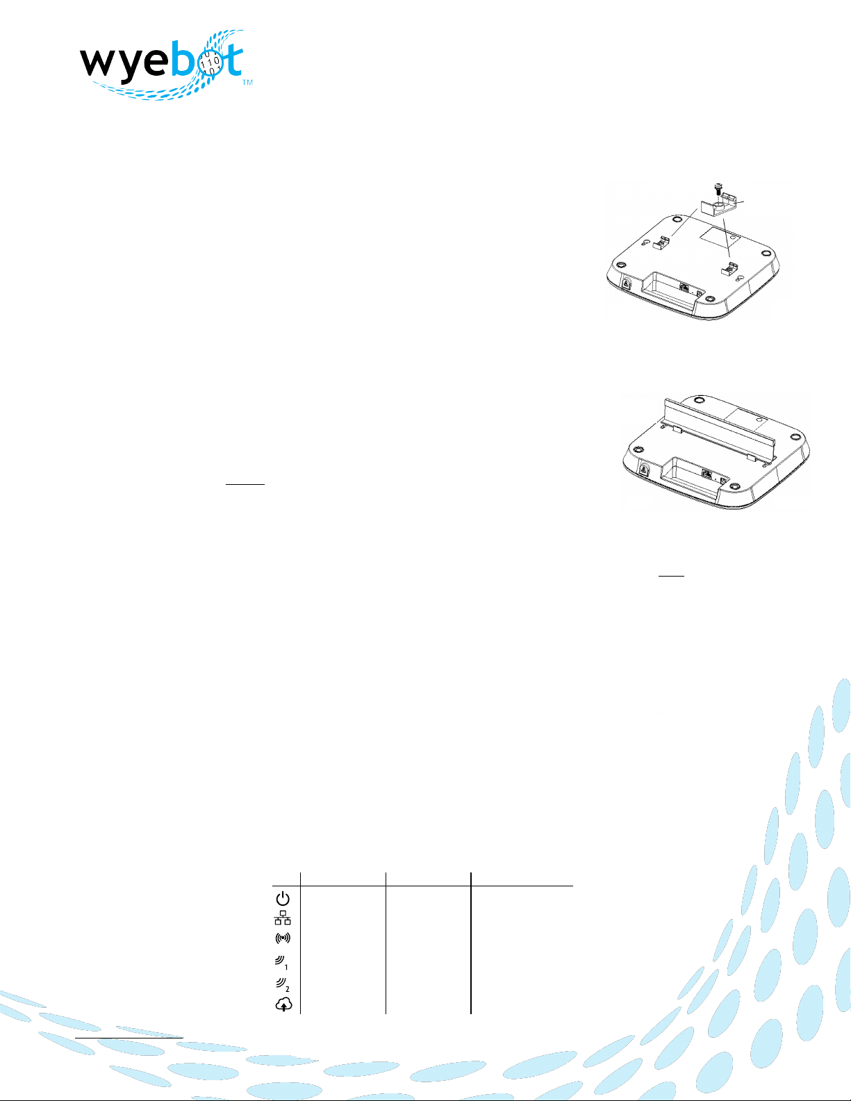
Suspended Ceiling Mount
Select the pair of ceiling rail clips (included) which match the width of your ceilings
T-bar rails. The provided clips support both 9/16” and 15/16” ceiling rails.
Using the two 8mm lock screws provided, attach the respective clips to the bottom of
the WIS4200. Ensure clips are aligned with the indented areas on the bottom of the
WIS4200 (See Fig. 1).
Attach the WIS4200 to a secure ceiling rail by attaching one clip at a time to the rail
(See Fig. 2). Verify the WIS4200 fits securely on the ceiling tile rail for the most secure
mounting.
Above Ceiling(Plenum Space)
The WIS4200 is suitable for use in environmental air space in accordance with Section 300-22(C) of the National
Electrical Code. Use above a suspended ceiling is permitted in a horizontal mounting position only. The optimal
orientation of the unit is with the top cover(logo) facing down toward the floor. Avoid placing the unit near
electrical wiring or ductwork in order to reduce the impact these items may have on RF signals.
Powering on the Unit
The WIS4200 may be powered with PoE (802.3af/at) or an optional AC/DC power adapter(available seperately).
Insert the Ethernet LAN cable into the port marked “1G/PoE”. If using the AC/DC adapter, insert the adapter
plug into the port labeled “12VDC” then plug adapter into AC outlet.
When power is first applied, the following sequence of LEDs occurs
•
Power LED on (amber)
•
Run through sequence for each of the LEDs (green)
•
All LEDs flash twice (green)
•
The Power LED will then remain on (color per table below) indicating the unit has started initialization.
•
When the Cloud LED has changed to green, the sensor has successfully connected to the cloud infrastructure
and started operation.
The complete LED definitions are listed below:
support@wyebot.com
2017 Wyebot, Inc. - Confidential
WIS4200 Quick Start Instructions Rev 1.2
T-bar
Rail
Fig. 2
Put bracket into
bottom indent
Lock screw
Fig. 1
Power
LAN (Wired)
LAN (Wireless)
Sensor Radio 1
Sensor Radio 2
802.3af
802.3at / Adapter
10/100
1G
2 GHz
5 GHz
2 GHz
5 GHz
2 GHz
5 GHz
Disconnected
Connected
Amber
Green
Name
Cloud
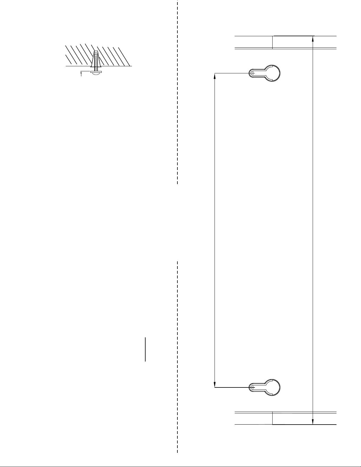
Wall Mounting Instructions
1. Using the template below, mark the position where you would like to mount the unit on the wall. Tape the template to the
wall as a guide for correctly locating the hole positions.
2. Drill a 6mm diameter hole at each position.
3. Insert the included wall anchors and 20mm screws into the respective holes, leaving the screw heads 4mm from the wall
surface (see Diagram to right). NOTE: The included wall anchors are NOT suitable for installation in a drywall ceiling.
4. Mount the unit to the screws.
CAUTION: RISK OF EXPLOSION IF BATTERY IS REPLACED BY AN INCORRECT TYPE.
DISPOSE OF USED BATTERIES ACCORDING TO THE INSTRUCTIONS
Cut here for template
4mm
USE FOR FLAT
WALL MOUNT ONLY
188mm (7.402")
232.61mm (9.158")
 Loading...