

Page 1

Single and Double Powerhead
Operator’s and Service Manual
®
Page 2

CONTENTS
INTRODUCTION• ..........................................................................................................3
SPECIFICATIONS• .........................................................................................................3
SAFETY•.........................................................................................................................4
GENERAL SAFETY• .......................................................................................................4
OPERATING SAFETY•..........................................................................................................................4
STORAGE SAFETY• ............................................................................................................................. 5
REFUELING SAFETY• .......................................................................................................................... 5
OIL LEVEL CHECK• .............................................................................................................................. 5
POWER UNIT ASSEMBLY• ............................................................................................6
PRE-ASSEMBLY• ................................................................................................................................. 6
FINAL ASSEMBLY• ........................................................................................................6
HANDLE ASSEMBLY• .......................................................................................................................... 6
THROTTLE ASSEMBLY• .......................................................................................................................7
WEIGHT ADJUSTMENT• ..................................................................................................................... 8
OTHER SETTINGS• .............................................................................................................................. 8
THROTTLE CABLE ADJUSTMENT• ...................................................................................................... 9
ATTACHING THE SCREED BAR• .......................................................................................................... 9
SERIAL NUMBER LOCATION• ............................................................................................................10
NOTES• ........................................................................................................................10
LIMITED WARRANTY• ................................................................................................11
Power Head #1 Model
Power Head # 1 Serial Number
Power Head #2 Model
Power Head # 2 Serial Number
Screed Bar Model
Screed Bar Serial Number
Date Purchased
Page 2Form: 01-SCR-UM-00442 Rev 6/12
Page 3

INTRODUCTION
Congratulations on your choice of a Wyco Screed King power screed to complement your construction
operation. This equipment has been designed and manufactured to meet the needs of a discriminating
buyer for the ecient nishing of concrete.
Safe, ecient and trouble free operation of your Wyco Screed King power screed requires that you and
anyone else who will be operating or maintaining the screed, read and understand the Safety, Operation,
Maintenance and Trouble Shooting information contained in the Operator’s Manual.
Keep this manual handy for frequent reference and to pass on to new operators or owners. Call Wyco
Tool or your dealer if you need assistance or information.
Operator Orientation - The directions left, right, front and rear as mentioned throughout this manual, are
as seen from behind the machine, standing between the handles.
SPECIFICATIONS
Engine GX35 Mini 4-Stroke
Starting Mechanism Recoil
Maximum Power Output 1.5 HP @ 7000 RPM
Handle Design Vibration reducing, quick adjusting
Fuel Capacity 0.17 U.S. Gallon (0.644 Liter)
Oil Capacity 3.4 ounce U.S. Liquid (0.1 Liter)
Sound Pressure 87-90 dB(A) @ 5500 RPM
Vibration (m/sec2) 7.4 m/sec @ 5500 RPM in 4" slump concrete
Power Head Weight
Screed Bar Weight
Single Powerhead alone 27 12.25
Dual Powerhead alone 54 24.25
4 foot screed bar 8 3.63
5 foot screed bar 10 4.54
6 foot screed bar 12 5.44
8 foot screed bar 15 6.80
10 foot screed bar 19 8.62
12 foot screed bar 22 9.98
Lbs. Kg
Lbs. Kg
14 foot screed bar 26 11.79
16 foot screed bar 29 13.15
16 foot screed bar (double power unit) 31 14.10
18 foot screed bar (double power unit) 33 14.97
20 foot screed bar (double power unit) 37 16.78
Page 3Form: 01-SCR-UM-00442 Rev 6/12
Page 4

SAFETY
GENERAL SAFETY
YOU are responsible for the SAFE
operation and maintenance of your
Wyco Screed King power screed. YOU
must ensure that you and anyone
else who is going to operate, maintain or work
around the screed be familiar with related SAFETY
information contained in this manual. This manual
will take you step-by-step through your working
day and alerts you to all good safety practices that
should be adhered to while operating the screed.
Remember YOU are the key to safety. Good safety
practices not only protect you but also the people
around you. Make these practices a working part of
your safety program. Be certain that EVERYONE operating this equipment is familiar with the recommended operating and maintenance procedures
and follows all of the safety precautions. Most
accidents can be prevented. Do not risk injury or
death by ignoring safety practices.
* Screed owners must give operating instructions
to operators or employees before allowing them to
operate the machine, and at least annually thereafter.
1. Read and understand the Operators
Manual and all safety signs before
operating, maintaining, adjusting,
servicing or cleaning the screed.
2. Only trained competent persons shall operate
the screed. An untrained operator is not qualied to operate the machine.
3. Have a rst aid kit available for use
should the need arise and know how
to use it.
4. Have a re extinguisher available for
use should the need arise and know
how to use it.
5. Wear appropriate protective gear. This
list includes but is not limited to:
-A hard hat
-Protective boots with slip
resistant soles
-Protective goggles
-Heavy gloves
-Hearing protection
* The most important safety device on this equipment is a SAFE operator. It is the operator’s responsibility to read and understand ALL Safety and
Operating instructions in the manual and to follow
these. All accidents can be avoided.
* A person who has not read and understood all
operating and safety instructions is not qualied
to operate the machine. An untrained operator
exposes himself and bystanders to possible serious
injury or death.
* Do not modify the equipment in any way. Unauthorized modication may impair the function
and/or safety and could aect the life of the equipment.
6. Stop engine, disconnect spark plug wire and
wait for all moving parts to stop before servicing, adjusting, repairing or cleaning.
7. Wear appropriate hearing protection
when operating for long periods of
time
8. Review safety related items with all personnel
annually.
OPERATING SAFETY
1. Read and understand the operators manual and all
safety signs before operating, servicing, adjusting or
cleaning the screed.
2. Clear the area of all bystanders before starting.
Page 4Form: 01-SCR-UM-00442 Rev 6/12
Page 5

3. Keep hands, feet, hair and clothing away from mov-
ing parts.
4. Stay away from hot engine components during
operation.
5. Do not run screed in an explosive atmosphere or in a
poorly ventilated or enclosed area.
OIL LEVEL CHECK
OIL FILLER CAP/DIPSTICK
6. Stop engine, disconnect spark plug wire and wait for
all moving parts to stop before servicing, adjusting,
repairing or cleaning.
7. Do not smoke when refueling gas engine.
STORAGE SAFETY
1. Store unit in an area away from human activity.
2. Do not permit children to play around the stored
screed.
REFUELING SAFETY
1. Handle fuel with care. It is highly ammable.
2 This is a four cycle engine, use non-mixed gaso-
line of no less than 87 octane.
3. Allow engine to cool for 5 minutes before refueling.
Clean up spilled fuel before restarting engine.
LOWER LIMIT
OIL FILL HOLE
(bottom edge)
OIL FILLER HOLE LOCATION
It is important that the engine oil level be maintained at the correct level. High or low oil levels will
cause permanent damage to the engine requiring
replacement. To check the oil level:
Place the screed board on a at level surface. This will
1.
ensure that the engine is in the proper orientation to
perform an oil level check
2 Carefully unscrew the oil ller cap/dipstick and
wipe it clean.
Insert and remove the oil ller cap/dipstick without
3.
screwing it into the oil reservoir neck, then remove it
to check the oil level shown on the dipstick.
4. Do not refuel the machine while smoking or when
near open ame or sparks.
5. Always use an approved fuel container.
6. Fill fuel tank outdoors.
7. Prevent res by keeping machine clean of accumu-
lated trash, grease and debris.
4. If the oil level is near or below the lower limit mark
on the dipstick, ll the reservoir to the bottom edge
of the oil ll hole with the recommended oil (see
Honda engine owners manual). To avoid overlling
or underlling, be sure the engine is in a level posi-
tion as shown when adding oil
5. Reinstall the oil ller cap/dipstick and tighten se-
curely..
Notice: Running the engine with a low oil level can
cause engine damage. This type of damage is not
covered by the warranty.
Page 5Form: 01-SCR-UM-00442 Rev 6/12
Page 6
POWER UNIT ASSEMBLY
FINAL ASSEMBLY
PRE-ASSEMBLY
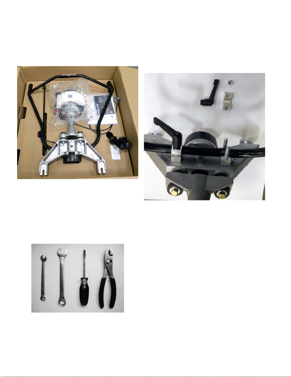
1. Check box to make sure all parts were received
and undamaged.
HANDLE ASSEMBLY
Remove the handles from their shipping position
by removing the two top ⁄” nuts, the quick release levers and the top handle cap.
COMPONENTS IN SHIPPING CONTAINER
2. The tools you will require for assembly are:
(1) ⁄” Open or box end wrench
(1) ⁄” Open or box end wrench
(1) #2 Flathead screwdriver
(1) Slip joint pliers
REQUIRED TOOLS
HANDLE PLATE POSITIONING
Insert the bottom of the handles into the back of
the handle plate and replace the top handle cap
over the handle. Thread on the two top ⁄” nuts.
Then install the quick release levers on the top of
each bracket. Placing the black hand levers in the
lower position will result in handlebar movement.
With the lever in the open position thread it
through the cap, handle plate and quick release
nut, continue threading until tight. When hand
tight place the handles at the appropriate height
and close the lever.
Add the upper handle sections to the lower handle
section and secure with the two ⁄” fasteners supplied.
Page 6Form: 01-SCR-UM-00442 Rev 6/12
Page 7
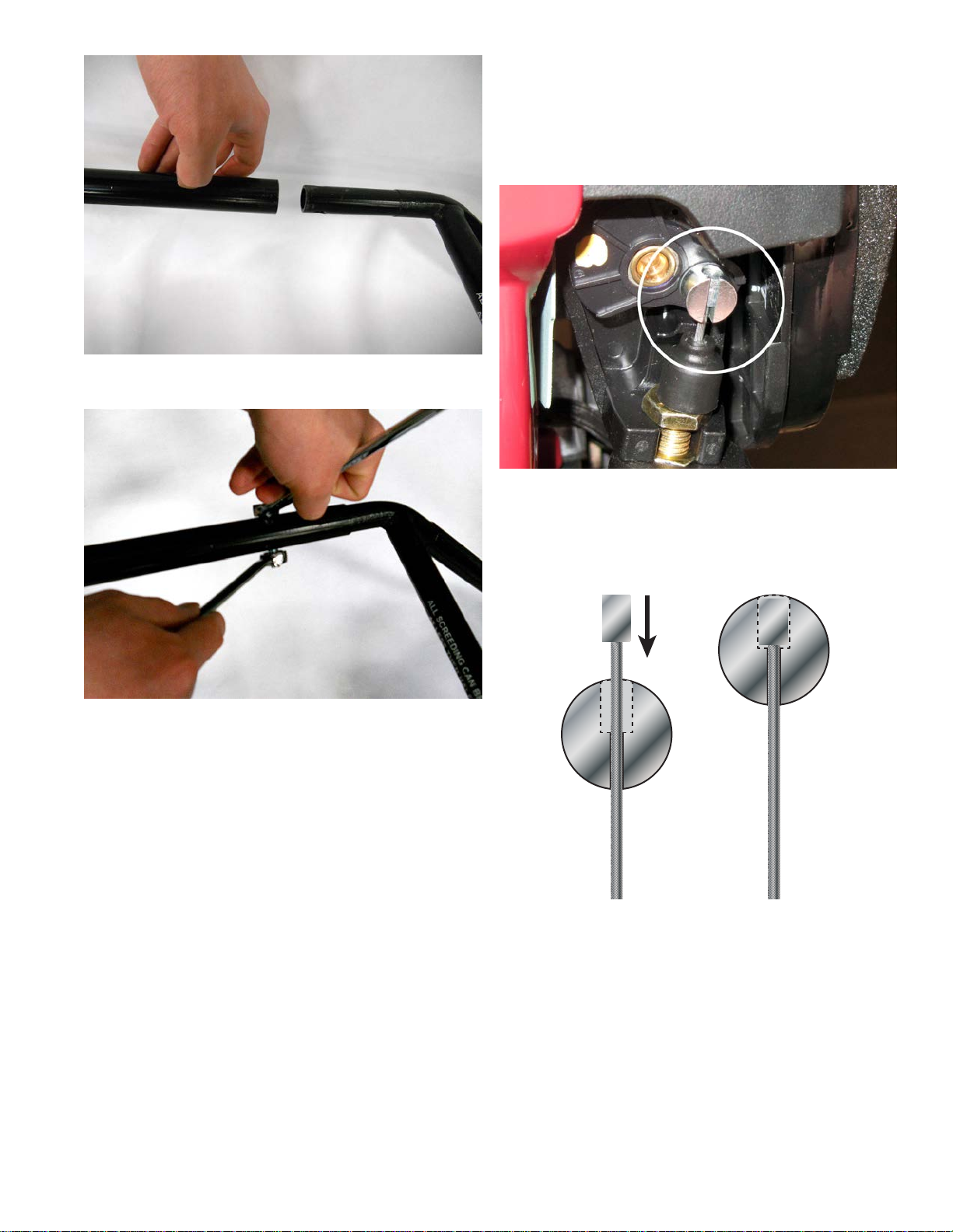
UPPER HANDLE INSERTION
Check to make sure the throttle adjustment cable’s,
cable stop is fully seated into the throttle adjustment linkage on the carburetor. The metal cable
stop should be completely inside the throttle
adjustment linkage as shown.
THROTTLE ASSEMBLY LOCATION
FASTENING UPPER HANDLE
THROTTLE ASSEMBLY
Place the throttle lever on the left hand handle just
below the hand grip. Position the lever so it clears
the handle guard in all positions. Place the lever
ring clamp around the handle bar and tighten with
a athead screwdriver and adjustable pliers. Use
the zip ties provided to keep the throttle cable
tight to the handle bars.
Correct
THROTTLE ASSEMBLY DETAIL
If the cable stop is not fully seated, loosen the
throttle control adjustment screw and grab the
end of the adjustment cable with the slip joint pliers. Pull gently on the cable until the cable stop is
completely within the throttle adjustment linkage.
Page 7Form: 01-SCR-UM-00442 Rev 6/12
Page 8
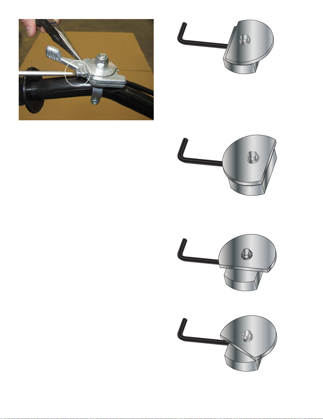
THROTTLE ASSEMBLY CONNECTION
With the throttle lever pushed to the far right hold
the throttle adjustment cable so there is no slack
and then tighten throttle control adjustment screw
to clamp the cable in place.
WEIGHT ADJUSTMENT
The eccentric weight on the power head is factory set to its maximum force. This setting will
settle concrete with a 2” to 8” slump. The only time
weight should be adjusted is when the screed is
going to be used on unusually high slump concrete.
LEAST VIBRATION
Turning the thin weight counter clockwise increases the force of vibration until the at edge of the
thin weight is ush with the opposite edge of the
thick weight.
MAXIMUM VIBRATION (FACTORY SETTING)
OTHER SETTINGS
To change the force of vibration, adjust the position of the eccentric weight as follows. Using a
¼” Allen key loosen the set screw on the thicker
weight. While holding the thick weight stationary
with the Allen key turn the thin weight by hand to
the desired position.
Turning the thin weight clockwise decreases the
force, it is zero when the at edge of the thin
weight is parallel to the at edge of the thick
weight with the set screw.
¾ VIBRATION
½ VIBRATION
Page 8Form: 01-SCR-UM-00442 Rev 6/12
Page 9
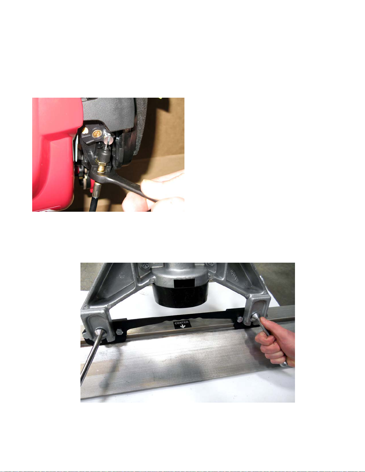
THROTTLE CABLE ADJUSTMENT
The throttle cable on the Screed King comes preassembled for your convenience. Over time you
may notice that it takes more clicks on the throttle
to get to optimum RPM level than when you rst
ran the screed. This is normal, over time your
throttle cable will stretch.
To adjust your throttle cable to compensate for this
stretching, simply locate the barrel adjuster where
the cable runs into the underside of the engine
and turn it counterclockwise with a 8 mm wrench.
Tighten the locknut to hold it in the desired position.
ATTACHING THE SCREED BAR
Locate the threaded studs on the screed bar and
loosen the locking handles. Slide the power head
of the screed over the threaded studs. Fasten the
power head to the bar using the locking handles
and washers provided, as shown below. The
washer and lock-washer should contact the silver
handles when installing the power unit. Make sure
to tighten the bolts fully so they do not vibrate
loose during use.
THROTTLE CABLE ADJUSTMENT
ATTACHING THE SCREED BAR
Page 9Form: 01-SCR-UM-00442 Rev 6/12
Page 10
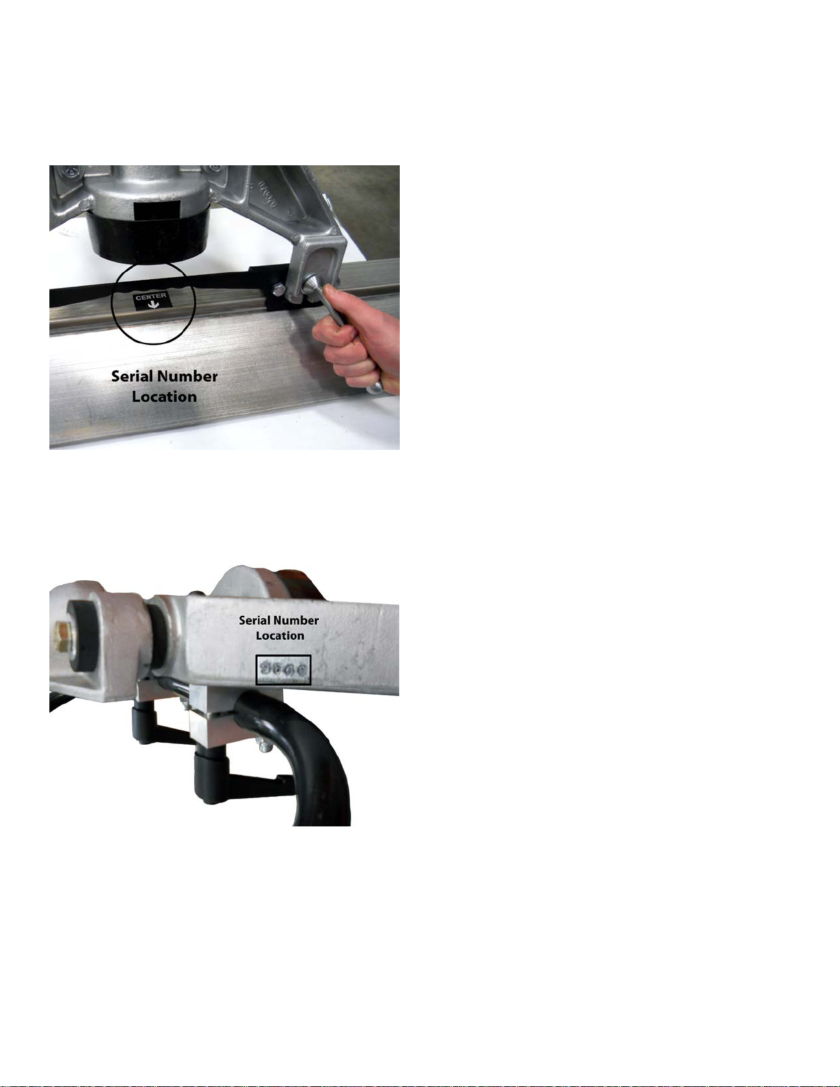
SERIAL NUMBER LOCATION
Always give your dealer, distributor or factory the
serial number of your power screed when ordering
parts or requesting service or other information.
NOTES
SCREED BAR SERIAL NUMBER LOCATION
The board serial number is stamped above the
“CENTER” sticker.
POWER UNIT SERIAL NUMBER LOCATION
The power head serial number is stamped in the
casting as shown above. Please record both serial number on the inside of the front cover in the
space provided.
Page 10Form: 01-SCR-UM-00442 Rev 6/12
Page 11

LIMITED WARRANTY
WYCO Tool, a Division of Racine Federated Inc. warrants that the products manufactured by it, when properly
assembled, used and maintained, shall be free from defects in material or workmanship, and will perform
according to the manufacturer’s specications under normal conditions, subject to the limitations stated in this
Manufacturer’s Limited Warranty.
WYCO’s obligation under this warranty shall be limited to repairing or replacing the part or parts, or, at WYCO’s
option, the products that prove defective upon return to the manufacturer’s factory. Cost of transportation and
other expenses connected with replacing parts are not covered.
WYCO’s obligation under this warranty is limited to a period of 24 months from the date of purchase for the power
head and 90 days for the screed bar. For the warranty to be valid the registration card must be completion and
return within 30 days of shipment of the Screed King power screed.
Written authorization from WYCO is required before any product can be returned for warranty consideration.
Always obtain a RGA number (Return Goods Authorization) and include it in the address before returning any
parts for warranty consideration or chargeable repair.
WYCO is not liable for any consequential damages or any contingent liabilities arising out of the failure of product
manufactured by it, or any component part or accessory.
This Manufacturer’s Limited Warranty is in lieu of all other warranties. All other warranties, either express or
implied, arising by operation of law, course of dealing, usage of trade or otherwise are excluded.
THERE ARE NO IMPLIED WARRANTIES OF MERCHANTABILITY OR FITNESS FOR A PARTICULAR PURPOSE.
No agent, representative or distributor has any authority to alter the terms of this warranty in any way.
See our complete statement of warranty at www.wycotool.com
Page 11Form: 01-SCR-UM-00442 Rev 6/12
Page 12

WYCO TOOL
8635 Washington Avenue
Racine, WI 53406-3738 USA
WYCO is a registered trademark of Racine Federated Inc.
UL is a registered trademark of Underwriters Laboratories.
Tel: 262-639-6770 or 800-233-9926
Fax: 262-639-2023 or 888-992-6872
Website: www.wycotool.com
E-Mail: [email protected]
© 2010 Racine Federated Inc., all rights reserved.
Printed in USA
Form: 01-SCR-UM-00442 Rev 6/12
 Loading...