

Page 1
Wyco High-Cycle Vibrator
Operator’s and Service Manual
®
READ ALL SAFETY PRECAUTIONS BEFORE OPERATING
1. POWER EQUIPMENT:
Make sure that the power supply equipment complies with the
relevant safety requirements of the local and international
- Electric Machine: Operator must ensure that the machine is
connected to the correct voltage and frequency specified on the
nameplate. The power supply cable has to be properly sized.
Check that the cable and the plug of the machine are not damaged.
WARNING: Never switch off the machine by pulling the
plug from its socket. Use the machine switch.
- Machine Powered By Gas or Diesel Engine: Gas has an
extremely low flash point and can be explosive in certain situations.
WARNING: Keep away from all hot or spark generating
objects, do not smoke when handling fuel. Wait until the
machine has cooled before filling the tank. Avoid spilling gas or
diesel fuel on the ground.
2. GENERAL SAFETY INFORMATION & EQUIPMENT:
Long time exposure to loud noise without ear protection can
cause permanent damage to hearing. Long time exposure to
vibration can cause damage to the hands, fingers & wrists. Do not
use the machine if you are experiencing discomfort, cramps or
pain. Consult a doctor before working again with the machine.
Always use approved safety equipment. The following safety
equipment applies to operators and other personnel in the
immediate vicinity of the working zone:
- Safety Helmet - Protective Gloves
- Ear Protection - Protective Shoes
- Dust Mask (dusty environments) - Eye Protection
standards.
2. GENERAL SAFETY INFORMATION & EQUIPMENT: (cont’d)
To avoid the risk of clothing being caught in the machine, avoid
wearing loose-fitting clothes. If you have long hair, cover it with a
hair net.
3. MACHINE KNOWLEDGE:
Before starting the equipment make yourself familiar with the
machine and make sure that the machine does not show any
obvious faults or wear. Then start the machine according to the
instructions and spare parts catalog.
4. OPERATION:
Use the machine only for the purpose for which it is intended.
Make sure you know how to stop the machine quickly in the event
of an emergency situation. Do not touch rotating parts during
operation.
5. MAINTENANCE:
Maintenance work must only be carried out by a skilled operator.
Keep unauthorize people away from the machine. Do not carry out
maintenance work while the machine is moving or while the engine
is running. Never use a machine that is damaged.
6. BE ALERT:
Always concentrate on what you are doing. Use common sense
and never operate the machine if you are tired or under the
influence of drugs, alcohol or other substances which can affect
your vision, reaction time, ability or judgement.
Manufacturers Limited Warranty
The WYCO Tool Company warrants that the products manufactured by it, when properly installed, used and maintained, shall be free
from defects in material or workmanship, and will perform according to the manufacturer’s specifications under normal conditions,
subject to the limitations stated in this Manufacturer’s Limited Warranty. WYCO’s obligation under this warranty shall be limited to
repairing or replacing the part or parts, or, at WYCO’s option, the products which prove defective upon return to the manufacturer’s
factory. Cost of transportation and other expenses connected with replacing parts are not covered. WYCO’s obligation under this
Warranty is limited to a period of 18 months from the date of shipment, or 12 months from the date of purchase by the first user of the
product, whichever is longer.Written authorization from WYCO is required before any product can be returned for warranty consideration.
WYCO is not liable for any consequential damages or any contingent liabilities arising out of the failure of product manufactured by it, or
any component part or accessory. This Manufacturer’s Limited Warranty is in lieu of all other warranties. All other warranties, either
express or implied, arising by operation of law, course of dealing, usage of trade or otherwise are excluded.
THERE ARE NO IMPLIED WARRANTIES OF MERCHANTABILITY OR FITNESS FOR PURPOSE.
No agent, representative or distributor has any authority to alter the terms of this warranty in any way
SAVE THESE INSTRUCTIONS
Page 2
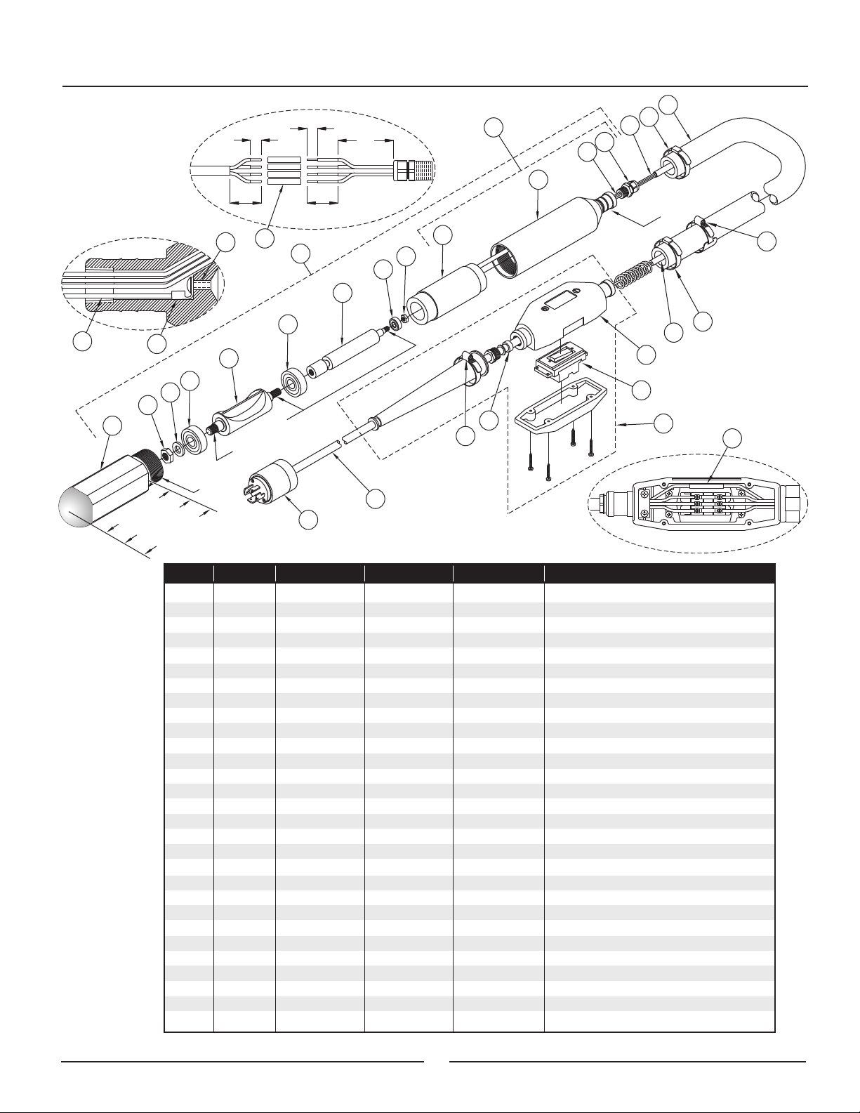
Service Instructions Drawing & Parts List
DISASSEMBLY INSTRUCTIONS ASSEMBLY INSTRUCTIONS
VIBRATOR HEAD: VIBRATOR HEAD:
- Hold square head (1) in a vise, leaving the stator housing (10) tilted
up so any oil will remain in the head and not leak out when
separated.
- Unscrew the stator housing (10) from the square head (1) using a
girth grip wrench and slowly remove it making sure that the motor
rotor (6) stays connected to the head.
- Remove the rotor assembly from head housing by pulling on the
motor rotor (6).
- Replace the following parts each time the vibrator head has been
disassembled: • 2 Bearings (4)
• Motor Rotor Bearing (7)
• Head Oil (See Page 4)
- To remove bearings (4) (7) from rotor (5) hold rotor in place using a
vise on the fin of the rotor.
- Loosen hex jam nuts (2)(8) and the motor rotor (6) and pull
bearings off. Note: These threads are all left hand.
WARNING: Never hold the motor rotor on the field (the
raised middle section) as this will permanently damage the
motor rotor.
SWITCH:
- Hold switch housing (26) in a vise with four screws facing up.
Note: Do not over-tighten housing in the vise as it may
damage the housing or internal parts.
- Loosen the four screws and lift the back plate off to allow access
to the switch and wires.
- Loosen the screws that hold the wires to the switch and remove
the wires from the switch. Note: Green wires are spliced with
connector and remain in place.
- Loosen the two screws that hold the switch to the housing and
remove the switch.
PLUG:
- Slide rubber boot off back of plug housing.
- Loosen two screws holding the cord to the plug housing.
- Loosen two screws holding the plug end in the housing.
- Slide the wire and plug end out to allow access to the individual
wire connections.
- Loosen the four screws and slide the wires out of their proper
termination points.
- Before re-assembly be sure to clean the inside and the outer
threads of the head housing (1) and rotor (5) to remove dirt, oil and
any impurities that may be present. Also clean the inside threads of
the stator housing (10).
- Check the condition of the stator (9) and inside the stator housing
(10), looking for chips in the epoxy coating and excessive wear on
the inside of the stator. Note: Removal of stator from housing is
not recommended since it has a tight press fit. If needed you
can purchase parts separately or as a kit (See Page 3).
- Refill with proper amount of Wyco #514-O non-foaming vibrator oil
(Wyco #655140): #1000 - 60mL
#1300 - 70mL
#1600 - 80mL
- Reverse disassembly procedures. Note: When reassembling
parts be sure to use loctite 242 on all threads that retain
bearings and use loctite 545 on threads holding the head (1)
to the stator housing (10).
- Before running repaired unit be sure to check clamps, protective
hose, wire, switch assembly and plug for any defects or damage.
(See Checklist on Page 4)
- After unit has been successfully repaired and tested according to
checklist, flip switch to the “ON” position. Insure that unit is running
properly by checking speed with tachometer and listening for a
constant, high and even pitch.
SWITCH:
- Before re-assembly be sure to inspect the housing for damage
and also clean inside the housing to remove dirt, oil and any other
object that may cause a short.
(23), gasket (24), rocker switch (25) and switch housing (26)
separately for repairs or buy the switch assembly kit (31)
complete.
- Reverse disassembly procedures. Note: When reattaching
wires to switch use following wiring:
White from Plug & Black #1 from Head to terminal 1
Red from Plug & Black #2 from Head to terminal 2
Black from Plug & Black #3 from Head to terminal 3
Green Wires are spliced together inside the switch
(See Page 3 - Switch Detail)
PLUG:
- Before re-assembly of the plug be sure to inspect the wires for
cuts in the insulation, loose wire strands or other conditions that
may cause a short. Note: Do not over-tighten screws to wires
or housing as this will strip threads or damage the plug,
rendering it unuseable.
- Reverse disassembly procedures. Note: When reattaching
wires to the plug use the following wiring instructions:
White Wires - X Black Wires - Y
Red Wires - Z Green Wires - W
Note: You can purchase the
2
nipple
Page 3
Grounding Detail
15
.38 (±.12)
.75 (±.12)
Wiring Detail
19
.38 (±.12)
.75 (±.12)
27
17
16
2.00
26
11a
10
9
12
11b
3M
p
i
r
G
h
tc
ve
i
o
s
c
e
S
h
d
A
7
4
8
20
8
7
6
13
14
4
5
4
3
22
21
18
16
2
1
5
e
it
t
oc
L
0#
0
0
1
00#
"=
3
5
1
6.
7.
00#
"=
6
5
1
"=
5
8.
Item
1
2
3
4
5
6
7
8
9
10
11a
12.5 In
11b
12
13
14
15
16
17
18
XX Ft*
XX+2 Ft*
19
20
21
22
23
24
25
26
27
28
42
2
e
it
t
oc
L
45
24
25
Qty #1000 Head #1300 Head
1
416024
1
1
2
1
416028
1
1
1
1
1
416016
432707
887011
096020
416020
416013
416021
432710
416012
416050
416048
8.5 In
1
6 In
1
1
2
416048
416023
221709
221706
416046
259601
416011
390255
5
2
1
1
1
25 Ft
1
1
1
1
416-051
416047
259606
417001
417000
416045
399400
399401
416-057
416-052
417-068
23
20
#1600 Head
416032
416036
416-053
Description
Housing, 2-3/8" Square Head
Nut, Hex Jam; 9/16"; Left Hand
Washer, Flat
Bearing, Ball
Rotor, Hi-Cycle
Rotor, Motor; High-Cycle
Bearing, Ball
Nut, Hex Jam; 5/16"; Left Hand
Stator, Motor; High-Cycle
Stator Housing; High-Cycle
Sleeving, Fiberglass; PVC Coated
Sleeving, Fiberglass; PVC Coated
Fitting, Strain Relief; 3/8" NPTF
Wire, #16 AWG; Green
Ring, Terminal; #10; High-Cycle
Screw, Button Head; #10-32 x 3/8"
Clamp, Center Punch; 2-3/4"
Hose, Protective; High-Cycle
Cable, Tray; 14 AWG; 4 Cond
Connector, Butt Splice
Clamp, Hose; #16
Switch, Rocker; w/o Housing
Assy, Switch Housing; w/Switch
Tubing, Rubber; Switch Bushing
Cord, 4 Conductor
Plug, Lock; 20A/250V/Gnd; 7411SS
Assy, Stator Housing; High-Cycle
Assy, Head; High-Cycle
Switch Kit, High-Cycle (For Replacement)
28
19
123
Switch Detail
* - XX is length of protective hose in feet.
3
Page 4
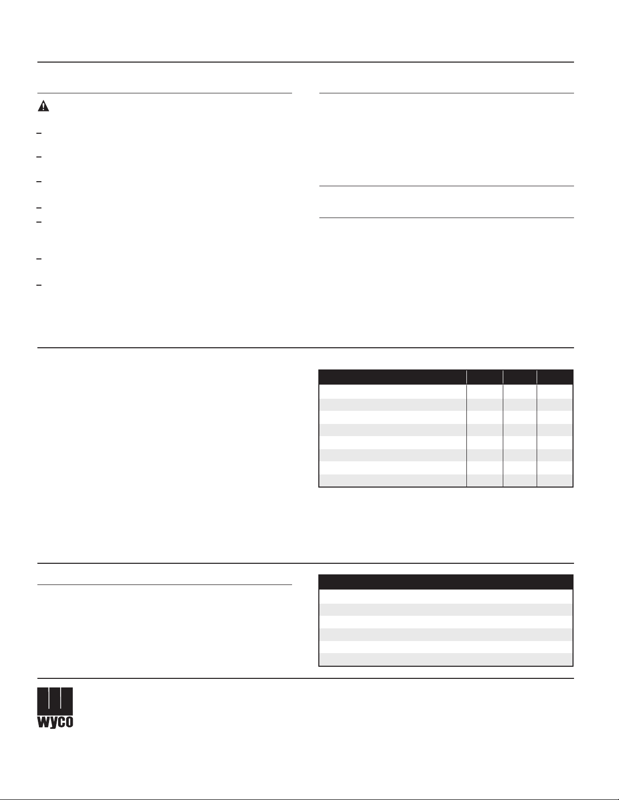
Operation, Technical Information & Accessories
OPERATING INSTRUCTIONS
CAUTION: After maintenance or repairs have been made
observe the following checklist to avoid serious injury:
Check wires (X,Y & Z) to insure there is no continuity between them
and ground (W).
Check wires (X,Y & Z) to insure there is no continuity between
them and steel on head housing.
Check cord for cuts, exposed wires or other conditions which
may cause an electrical hazard.
Check twist lock plug for damage to prongs or plug housing.
Check switch housing for damage or flaws that would allow dirt,
water or foreign objects to enter the housing and produce a short
or dangerous situation.
Check wires to insure there is 5 to 7 ohms across all wires (X,Y &
Check speed (VPM) with tachometer (example: Vibra-Tak).
Check that head moves from left to right when running with the
tip touching floor. If it moves from right to left, swap the #2 & #3
black wires on the head end of the switch.
WIRE WRAPPING OFF THE SWITCH:
The 4 wires running from the head to the switch must be coiled
properly. This is necessary to avoid pulling wires from their
termination points when the protective hose is bent sharply. Wrap
all 4 wires (#16 to #19) around a ½” piece of pipe and push into
switch end of hose. Feed wires through hose before wire wrapping.
GROUNDING ON HEAD:
Insuring a proper ground is essential in safe operation of Wyco
High-Cycle Vibrators. Wyco supplied vibrator heads have a unique
internal ground connection (Page 3 - Grounding Detail). To make
this connection follow these instructions: Cut a 6” section of
16 AWG green wire, strip back insulation and attach terminal ring
(14). To connect inside head bend the round end of the ring 90
degrees up. Guide button head cap screw (15) through terminal
ring. Attach allen wrench to screw while holding the wire (This will
allow you to guide the screw, wire and terminal ring into threaded
Z).
TO START:
1. Insure that power source corresponds to the frequency &
voltage marked on the nameplate located on switch housing.
2. Push and twist plug to secure into place on power source.
3. Flip the switch to the “ON” position or “I” on the switch housing.
4. After switching the unit “ON”, check that the unit is running
correctly: It should have a high, even pitch if running correctly.
TO STOP:
1. Flip the switch to the “OFF” position or “0” on the switch housing.
OPERATING HINTS:
1. Avoid bending the hose as much as possible at all times.
2. Do not use the vibrator head to spread the concrete.
3. The concrete has been thoroughly vibrated when the surface
around the head is shiny and no large air bubbles rise to the
surface (This normally takes 10 to 20 seconds at each location)
4. Withdraw the head slowly so that the concrete can flow back
into the void left by the head.
5. When finished, clean all concrete off the vibrator.
TECHNICAL DATA
Information Type #1000 #1300 #1600
16
60
18.30
17
70
.389
.087
710
1300
1605
19.30
18
80
.478
.100
874
1600
1975
Head Length (in)
Head Weight (lbs)
Head Oil (ml)
Eccentric Moment (in/lbs)
Amplitude Total at Tip (in)
Force at 133 Hz / 8,000 VPM (lbs)
Force at 180 Hz / 10,800 VPM (lbs)
Force at 200 Hz / 12,000 VPM (lbs
area inside the head and tighten). Slide a 2” piece of sleeving (11)
over ground wire and 3.5” piece over 3 other wires into head.
Guide these 4 wires through the 4 holes in strain relief fitting and
secure tightly to head using teflon tape.
17.30
.300
.073
546
1000
1234
ACCESSORIES
Wyco supplies the following accessories for use with High-Cycle
vibrators. Contact your local dealer or call a Wyco Customer
Sales Representative for details at 1-800-233-9926.
THE WYCO TOOL
COMPANY
®
8635 Washington Avenue • Racine, Wisconsin 53406-3738 USA
Te l ephone: (262) 639-6770 or 800-233-9926
Facsimile: (262) 639-2023 or 888-992-6872
Website: www.wycotool.com • E-Mail: [email protected]
Wyco is a registered trademark of Racine Federated Inc.
Select-Cycle is a trademark of Racine Federated Inc.
Turnlok is a registered trademark of Pass Seymour Inc.
Description Part No.
50 ft Extension Cord
100 ft Extension Cord
Select-Cycle™ Converter with 20 Amp Turnlok
Select-Cycle™ Converter with 30 Amp Turnlok
8 H.P. Honda High-Cycle Generator
Generator Wheel Kit
®
Plug
®
Plug
399-415
399-420
416-055
416-056
511807
511808
Form #W145 DJO
Printed in U.S.A. 8/07
 Loading...