

Page 1
Wyco Pneumatic
Operator’s and Service Manual
wwyyccoo
RRRR
“BD” Pneumatic Concrete Vibrators
READ ALL SAFETY INSTRUCTIONS
1. WORKING AREA: Do not operate a machine that is
powered by a gas or diesel engine in a poorly ventilated
space. These types of engines produce toxic gasses
which cause serious health problems.
2. POWER EQUIPMENT:
- Pneumatic Machine: Check that the compressed air
hose and the hose coupling are not damaged.
WARNING: Never attempt to loosen any
!
compressed air hose that is pressurized. First
switch off the air at the compressor and then allow the
machine to run to a stop to discharge any existing
compressed air.
- Machine Powered By Gas or Diesel Engine: Gas has
an extremely low flash point and can be explosive in
certain situations. WARNING: Keep away from all
hot or spark generating objects, do not smoke
when handling fuel. Wait until the machine has
cooled before filling the tank. Avoid spilling gas or
diesel fuel on the ground.
3. GENERAL SAFETY INFORMATION & EQUIPMENT:
The admissible sound of 85 dB (A), can be exceeded
because of the machine and/or the application. Long
time exposure to loud noise without ear protection can
cause permanent damage to hearing. Long time
exposure to vibration can cause damage to the hands
fingers and wrists. Do not use these vibrators if you are
experiencing discomfort, cramping or pain. Consult a
doctor before working again with the vibrator.
!
3. SAFETY INFORMATION & EQUIPMENT (cont’d):
Always use approved safety equipment. The following
safety equipment applies to operators and other
personnel in the immediate vicinity of the working zone.
- Safety Helmet - Protective Gloves
- Ear Protection - Protective Shoes
- Dust mask (dusty environments) - Eye Protection
`
4. MACHINE KNOWLEDGE: Before starting the equip ment make yourself familiar with the machine and
make sure that the machine does not show any
obvious faults or wear. Then start the machine
according to the instructions.
5. OPERATION: Use the machine only for the purpose
for which it is intended. Make sure you know how to
stop the machine quickly in the event of an emergency
situation. Do not touch rotating parts during operation.
6. MAINTENANCE: Maintenance work must only be
carried out by a skilled operator. Keep unauthorized
people away from the machine. Do not carry out
maintenance work while the machine is moving or
while the engine is running. Never use a machine that
is damaged.
7. BE ALERT: Always concentrate on what you are doing.
Use common sense and never operate the machine if
you are tired or under the influence of drugs, alcohol or
other substances which can affect your vision, reaction
time, ability or judgement.
TECHNICAL DATA
Type BD 35 BD 55 BD 65 BD 75
Head Diameter in(mm) 1.42(36) 2.20(56) 2.64(67) 3.03(77)
Head Length in(mm) 10.51(267) 13.54(344) 14.37(365) 15.67(398)
Head Weight lbs(kg) 3.3(1.5) 9.9(4.5) 17.38(7.9) 19.6(8.9)
Amplitude (Total at tip) in(mm) .027(.69) .037(.94) .054(1.37) .070(1.78)
Frequency (Max at 85 psi) (v.p.m.) 17,600 17,700 17,700 17,000
Centrifugal Force (Max at 85 psi) lbs(kg) 441(200) 1484(675) 2548(1158) 3278(1490)
Air Consumption (Max at 85 psi) (cfpm) 27 54 54 85
Page 2
Operation & Service Information
OPERATION AND MAINTENANCE
- CLEAR AIR SUPPLY LINE: Before connecting vibrator, clear the compressed air supply line of possible impurities,
contaminants and water.
- LUBRICATE: Every day or every four hours of continuous service, pour a ½ teaspoon of non-detergent (Viscosity 20
to 30 SAE) oil into the quick release coupling. NOTE: An optional oiler/strainer is available (See Page 3)
WARNING: So as to facilitate shipment, new or repaired units are not lubricated before delivery to customers.
!
WARNING: Do not use hydrocarbons and especially do not use fuel oil for lubricating purposes.
!
- CONNECT: Connect the vibrator to the quick release coupling securely. Insure that locking pin is in place.
- START: To start vibration, rotate the variable control assembly near the quick release coupling. It is sometimes
necessary to tap the head to begin vibration. If the vibration intensity drops, check that the filters are not clogged or that
hoses are not kinked.
- STORAGE: To properly store unit after use, hang the vibrator with the head up and set the handle (variable control
assembly) in the open position to permit the discharge of possible impurities, contaminants and water.
ASSEMBLY INSTRUCTIONSDISASSEMBLY INSTRUCTIONS
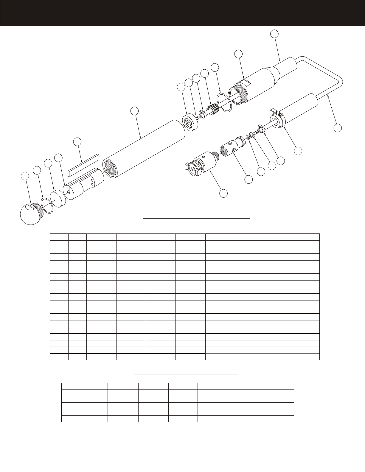
VIBRATOR HEAD:
- Hold vibrator head housing (6) in a vice and unscrew
the tip (1). (Right Hand Thread)
- Remove vibrator head from vice and tap vertically on a
wooden block. This will aid in the removal of the front
flange (3) and the rotor. (4)
- Again clamp vibrator head housing (6) in vice and
unscrew hose holder (11). (Left Hand Thread)
- Remove rear flange (7) (tap on wooden block again if
necessary), cut hose clamp (9) & remove inlet hose (13)
from flange nipple. (8)
- Unscrew the hose retain sleeve (10) & remove exhaust
hose (12). Also remove spring (See Optional Parts List)
from this hose only when it is provided.
- Cut hose clamp (14) on the outer end cap (17) and
remove exhaust hose. (12)
VARIABLE CONTROL ASSEMBLY:
- Unscrew the outer end cap (17) (Right Hand Thread).
Cut hose clamp (9) & remove inlet hose. (13)
- Remove screw from bushing. Remove body from bushing.
(Tap on a wooden block if necessary).
Note: Make use of the maintenance kits (See Page 3)
VIBRATOR HEAD:
- Reverse previous procedures.
- Replace the following parts each time the vibrator head
has been disassembled:
- Vane (5) - O-Rings (2 & 16)
- Filter (on quick disconnect) - Hose Clamps (9 & 14)
- Slightly lubricate all parts before reassembly.
- Adjust the new vane (5) so that it slides snug in the
groove in the rotor (4). Note: Be sure that vane (5) slots
are facing away from cutout in rotor (4).
- Check the condition of front (3) & rear (7) flange &
replace them if there is a hollow area where the rotor
turns.
- Reassemble tip (1) & outer hose holder (11) making
sure that the O-rings (2) are in place.
VARIABLE CONTROL ASSEMBLY:
- Reverse previous procedure.
- Replace O-rings on body making sure you do not cut
O-rings when sliding body back into bushing.
- Reassemble all hoses onto the vibrator head assembly
and reattach the on/off control valve.
* When screwing tip and hose holder into housing torque
as follows:
- BD 35 37ft/lbs - BD 65 434 ft/lbs
- BD 55 246 ft/lbs - BD 75 636 ft/lbs
2
Page 3
Drawing & Parts List
1212
1111
22
1010
99
88
77
66
1313
55
1414
44
33
22
11
1818
1616
1717
99
1515
Item
1
2
3
4
5
6
7
8
9
10
11
12
13
14
15
16
17
18
Qty
1
1
1
1
1
Qty
1
2
1
1
1
1
1
1
2
1
1
Ft
Ft
1
1
1
1
1
BD35
182619
*160311
368071
*182623
368072
182625
182626
*259602
102623
182627
682021
689000
*259601
368070
*892635
368073
183920
BD35
183568
187917
680770
680765
-
BD55
182905
*160014
182635
368065
*182637
368066
182639
105521
*259602
101582
185277
682781
689100
*259601
368064
*892635
368063
183920
BD55
183571
187919
680770
680765
STANDARD PARTS LIST
BD65
182641
*160217
182643
368061
*182645
368062
184110
105521
*259602
101582
182649
682781
689100
*259601
368064
*892635
368063
183920
BD75
183031
*924834
182650
368047
*182653
368048
182655
107690
*259602
101604
182907
680541
689500
*259601
368059
*892635
368049
183920
Description
Tip, Pneumatic
O-Ring, Buna-N; 70 Dur
Flange, Front; Pneumatic
Rotor, Pneumatic
Vane, Pneumatic
Housing; Pneumatic
Flange, Rear; Pneumatic
Nipple, Flange; Pneumatic
Clamp, Hose; Bandit; Jr.
Sleeve, Hose Retain
Holder, Hose; Pneumatic
Hose, Pneumatic; Exhaust
Hose, Pneumatic; Inlet
Clamp, Center Punch; 2-3/4”; Steel
Barb, Inner Hose; Pneumatic
O-Ring, Buna-N; 70 Dur; Hose Barb
End Cap, Outer Hose
Assy, Variable Control; Pneumatic
OPTIONAL PARTS LIST
BD65
183579
187920
680770
680765
BD75
183582
101479
187921
680770
680765
Description
Tip, Rubber; Pneumatic
Spring, Hose Protection; BD75
Maintenance Kits
Assy, Pneumatic Oiler
Assy, Pneumatic Strainer
3
Page 4
Wyco Pneumatic
Operation Information
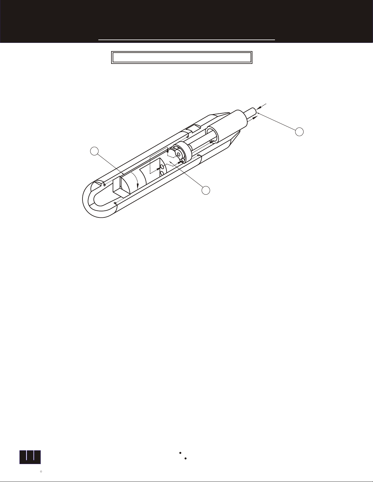
PRINCIPLES OF OPERATION
BD 35, 55, 65 & 75 are all of similar design and construction. They feature a built-in pneumatically driven motor which has
only two moving parts, the vane(1) and rotor (2). Compressed air is supplied to the vibrator through the air valve and inner
hose (3). Air flows into the rotor, passes through the passage ways in the vane, back through the “air gap” on the rotor and
outer holes in the rear flange. This activates the rotor and the vibrator begins to vibrate.
33
11
22
wyco
THE WYCO TOOL
R
COMPANY
P.O. Box 081580 Racine, Wisconsin 53406
8613 Washington Ave Racine, Wisconsin 53406
Telephone: (262) 639-6770 or 1-800-233-9926
Fax No: (262) 639-2023 or 1-888-992-6872
Form #W139 DJO
Printed in U.S.A. 12/04
 Loading...