

Wyckomar UV-1, UV-700, UV-250, UV-1200, UV-1500 Installation And Maintenance Manual
...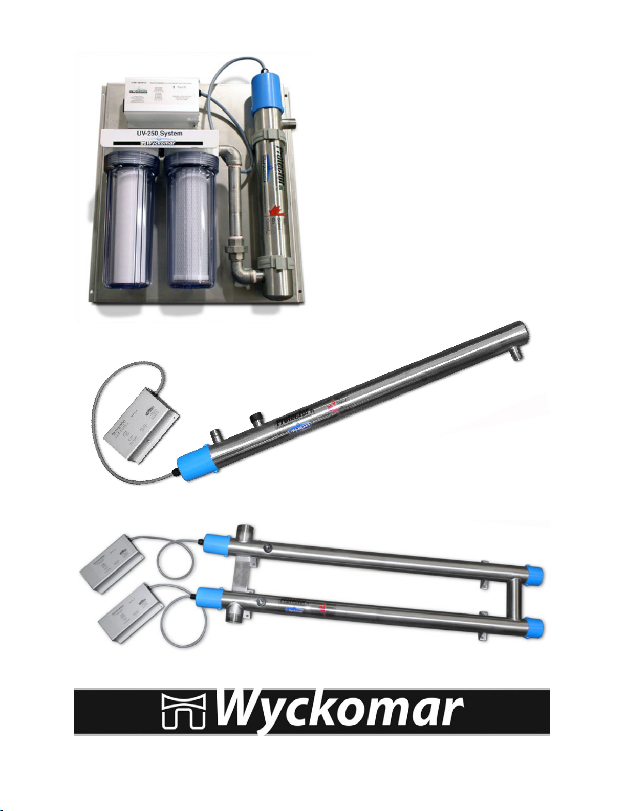
UV Purication Systems
Installation and
Maintenance
Manual
Models:
UV-1, UV-250,
UV-700, UV-1200, UV-1500,
UV-3000, UV-5000 and UV-6000
Copyright
Copyright by Wyckomar Inc. 2014. No part of this manual may be reproduced or transmitted in any
form without the expressed, written permission of Wyckomar Inc.
Notice
Although Wyckomar has attempted to ensure the accuracy of the content of this manual, it is possible
that this document may contain technical inaccuracies, typographical, or other errors. Wyckomar assumes no liability for any error in this publication, and for damages, whether direct, indirect, incidental,
consequential or otherwise
Wyckomar provides this publication “as is” without warranty of any kind, either expressed or implied.
Use of the system is at the discretion of the buyer.
The published information in this manual is subject to change without notice. Wyckomar reserves the
right to make changes in the product design and layout without notication to its customers.
Please read this entire User Manual
before attempting to install your UV system.
Read and follow ALL safety precautions
Keep this manual in a safe place
for future reference.
Unit Serial Number:
Date of Purchase:
Please keep your sales receipt as proof of purchase for warranty purposes.
CAUTION - WARNING
The ballast and all electrical connections MUST
be mounted and installed ABOVE the water lines
to prevent the possibility of electrical shock in
case of a water leak.
See “Safety Precautions” on Page 4
UV Purication Systems
1
Congratulations on purchasing a Wyckomar UV purication system. Please read
through the installation procedures and follow all safety warnings when setting
up your system. Wyckomar Inc. manufactures several sizes of UV purication systems; however, they all operate on the same principle. Basic installation is the
same for most units. Refer to the exploded view diagrams for replacement parts.
Table of Contents
Section 1 - Introduction
How Ultraviolet Water Purication Works
How Your Wyckomar UV Water Purier Works
Section 2 - Setting Up
Safety Precautions
Important Considerations
Installation Diagrams
Installation
Start Up Operation
Section 3 - Maintenance
Disinfecting Your Water System
Ultraviolet Lamp Replacement
Quartz Dome or Sleeve Replacement / Cleaning
Changing Filter Cartridges
Filter Maintenance and Troubleshooting
Troubleshooting Guide
Section 4 - Technical Info
Exploded Diagrams and Parts Lists
Section 5 - Accessories
Filter Sets and Cartridges
UV Monitoring System
Remote Output and Operation Logging
Purge Valve, Hour Meter
Section 6 - Contact and Warranty
Wyckomar Contact Info
Warranty Registration Card
Introduction
Page
2
3
4
5
6
7
8
9
10
11
12
13
22
14 - 21
23
24
25
26
27
28

UV Purication Systems
2
Introduction
How Ultraviolet Water Purication Works
Wyckomar Ultraviolet (UV) Puriers utilize the proven principle of ultraviolet light
radiation to eliminate or reduce unacceptable levels of microorganisms in water
and other liquids. Ultraviolet light energy destroys bacteria, viruses, fungi, spores,
algae and other such contaminants, which are pathogenic to humans, animals and
plants.
Ultraviolet purication is a completely natural, non-chemical, environmentally safe
technique, which adds nothing to, and removes nothing from the water (such as
trace minerals).
Factors Affecting UV Purication
The Wyckomar UV Purier is guaranteed to eliminate microbiological contamina-
tion only if the physical qualities of the inuent water supply are as follows:
Turbidity (Suspended Solids): Turbidity must be < 1.0 NTU at the time of disin-
fection. There must be a 5-micron or less sediment preltration system installed
before the UV system.
TDS (Total Dissolved Solids): Should not exceed approximately 500 ppm.
Total Hardness (Sum of Calcium & Magnesium): Must be < 10 gpg (grains per
gallon) of hardness, otherwise pretreatment is required.
Tannins & Colour: Must be < 2.0 ppm, or pretreatment is required.
Iron: Must be < 0.3 ppm.
Manganese: Must be < 0.05 ppm.
If your water quality parameters do not meet these criteria,
please contact the manufacturer for pretreatment recommendations.
UV Purication Systems
3
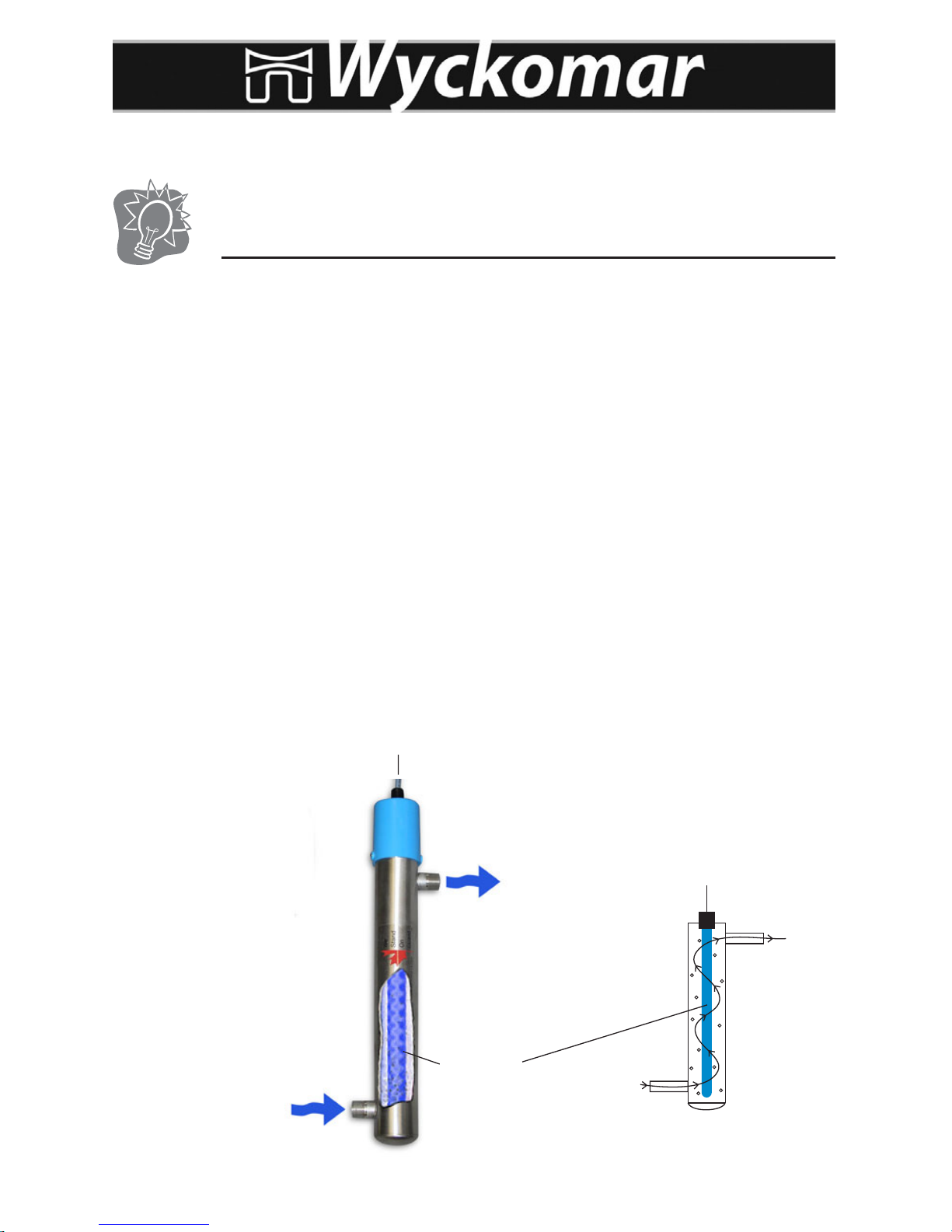
Untreated water enters the lower portion of the purication chamber and ows
through the unit in an upward circular path. The spiraling movement assures the
maximum irradiation of the uid and helps prevent larger particles from blocking
the treatment of microorganisms. The purication chamber contains the ultra-
violet light-producing lamp. In operation, the lamp emits a bluish glow, which is
visible in the view port window on the side of some units. WARNING: DO NOT
LOOK AT THE UV LIGHT DIRECTLY. Looking through the view port is safe, since
the glass disc in the view port lters out the UV rays. On systems equipped with
a UV monitor, do not look at the UV light through the view port, as the quartz disc
that is used in this case does not lter out the UV rays.
If your unit does not have a view port, operation of the UV light is conrmed by a
green LED indicator lamp on the ballast. As long as the appropriate indicators are
glowing, the unit is working properly. An alarm will sound when the UV lamp is
not functioning. When the alarm is sounding, the lamp must be replaced for the
unit to operate properly. The alarm sounds also when the ballast is damaged for
any reason (e.g. from moisture buildup inside, or from having received a power
spike or lightning strike).
Introduction
How Your Wyckomar UV Water Purier Works
Untreated water IN
Treated water OUT
UV Lamp
To Power Source

UV Purication Systems
4
Setting Up
Safety Precautions
Please READ and FOLLOW all safety precautions.
SAVE these instructions.
Never expose your eyes directly to UV light.
This UV system is designed for indoor use only. Do not use this UV system where
it may be exposed to the elements. Protect the unit from freezing at all times.
ELECTRICAL SHOCK HAZARD
This UV system is installed near water. Please take all necessary precautions.
Other than where noted in this manual, DO NOT attempt to repair parts yourself,
but contact the manufacturer or authorized dealer for repair service.
The electronic ballast in this system can get damaged from voltage and/or frequency deviations, caused by power outages or lightning strikes. Only connect
this UV system to a properly grounded outlet. A GFCI circuit is recommended.
It should not be plugged into the same circuit as a water pump, since the on/off
cycle of the pump can cause voltage spikes in the line.
It is highly recommended, especially in rural areas, to install a quality voltage
regulator or surge suppressor, rated at > 3600 Joules at the power input
to the ballast.
In older homes, the installation of plastic water treatment devices such as lter
housings may interrupt the water pipe’s electrical continuity to ground. This can
lead to pinhole leaking due to electrolysis or stray current corrosion. For prevention, the piping has to be properly bonded and grounded. Contact a professional
plumber for information.
Ensure installation is in compliance with all local laws, regulations and codes.
DO NOT operate the UV system if the power cord, plug or any electrical compo-
nent appears to be damaged or if the unit has been dropped or damaged in any
way. Inspect the UV system after installation, and carefully check for leaks. DO
NOT plug in the system if there is water on any part(s) that are not intended to
be wet.
This system is to be used ONLY for its intended use of potable water disinfection.
DO NOT use attachments that are not approved by the manufacturer, as this may
cause problems with the UV system.

UV Purication Systems
5
Setting Up
Important Considerations
Wyckomar puriers are installed either at the main water supply line or at point
of use. In some installations, particularly where plumbing is old, the water may
become re-contaminated in the pipes between the purier and the faucet. Be sure
to follow instructions under “Disinfecting Your Water System” on Page 9
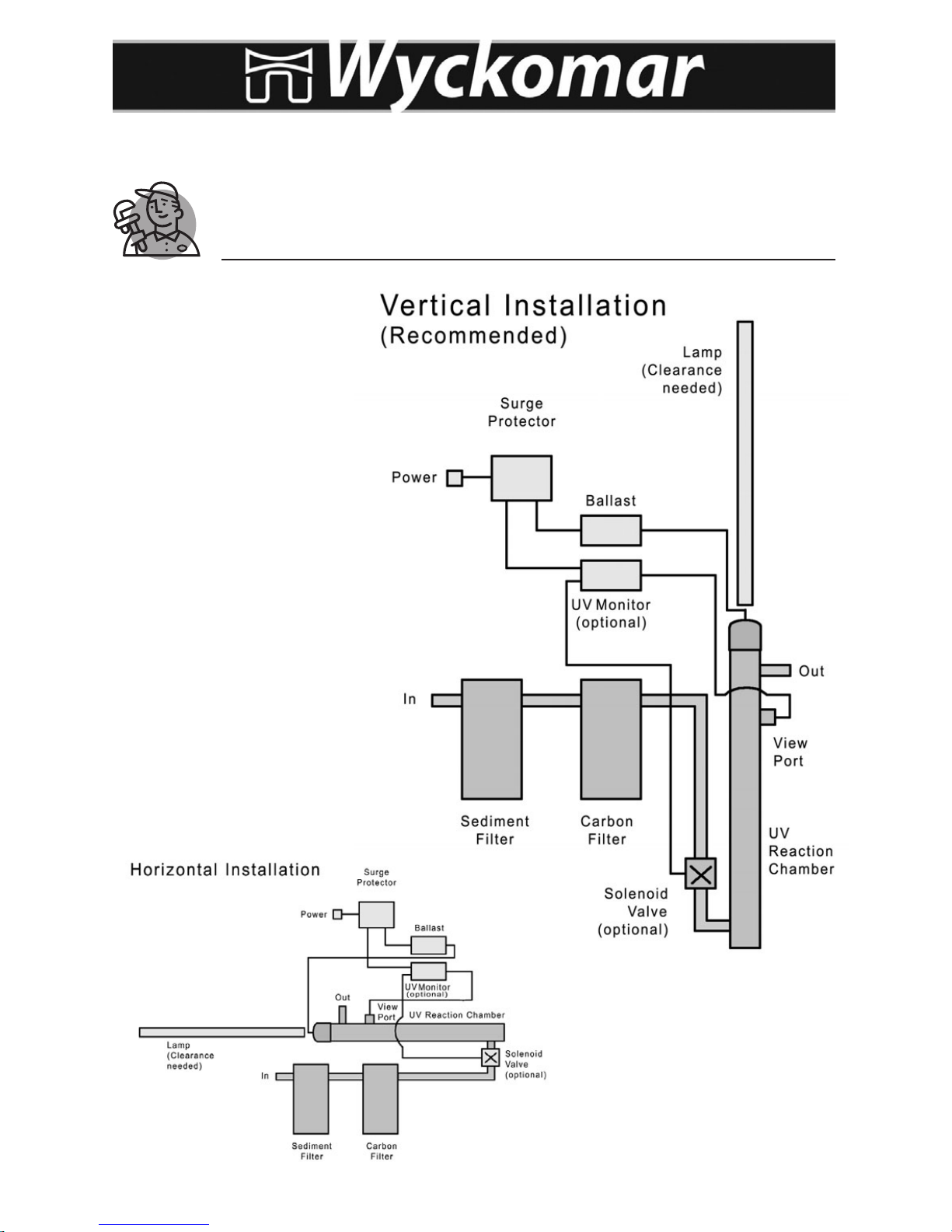
Wyckomar puriers are designed to be installed vertically and work best when
mounted in this position. However, in cases with space restrictions, the unit may
be mounted horizontally (see Installation Diagrams on Page 6).
Important: Clearance to the side or above the unit for lamp exchanges
should be equal to the length of the purier.
The manufacturer’s warranty is only applicable when preltered water is used.
Prelters (to 5 micron) remove sediment particles that can reduce the effective-
ness of the UV lamp or potentially damage the unit.
If a water softener, iron removal system or other treatment device is installed or
planned for, your purier should be located closest to the faucet.
Install your Wyckomar purier indoors in a protected area. The temperature should
not fall below 4 ˚C (40 ˚F). Avoid conditions with high humidity to prevent con-
densation on the purication chamber. Ideal temperature conditions range from
9 ˚C to 29 ˚C.
Use Teon tape (T-tape) liberally on all pipe connections (3 turns around the t-
ting). Do not use any other sealants other than food grade pipe dope.
Use food-grade silicon or plumber’s grease on O-rings. DO NOT use oil-based
products.
Caution: The ballast and all electrical connections must be mounted and installed above water lines to prevent the possibility of electric shock in the case
of a water leak. A grounded electrical outlet is required (GFCI is preferred).
UV Purication Systems
6
Setting Up
Installation Diagrams
Wyckomar systems can be
installed vertical or horizontal. Refer to these sche–
matic drawings for typical
position of components.
Ensure that there is adequate clearance at the lamp
end of the unit in order to
safely remove the UV lamp
from the chamber. Space
required for clearance is at
least the length of the UV
chamber.
UV Purication Systems
7
Setting Up
Installation
Carefully select the location for the UV system and any related components. Note
the direction of water ow in the supply line to which the unit is being connected.
Refer to the appropriate exploded view diagram for your unit and check to see that
you have all the necessary ttings.
Parts List: 4 screws 1 quartz dome or sleeve, 1 or 2 O-rings
1 alcohol wipe 1 Allen key wrench
1 UV lamp w/ O-rings on each end
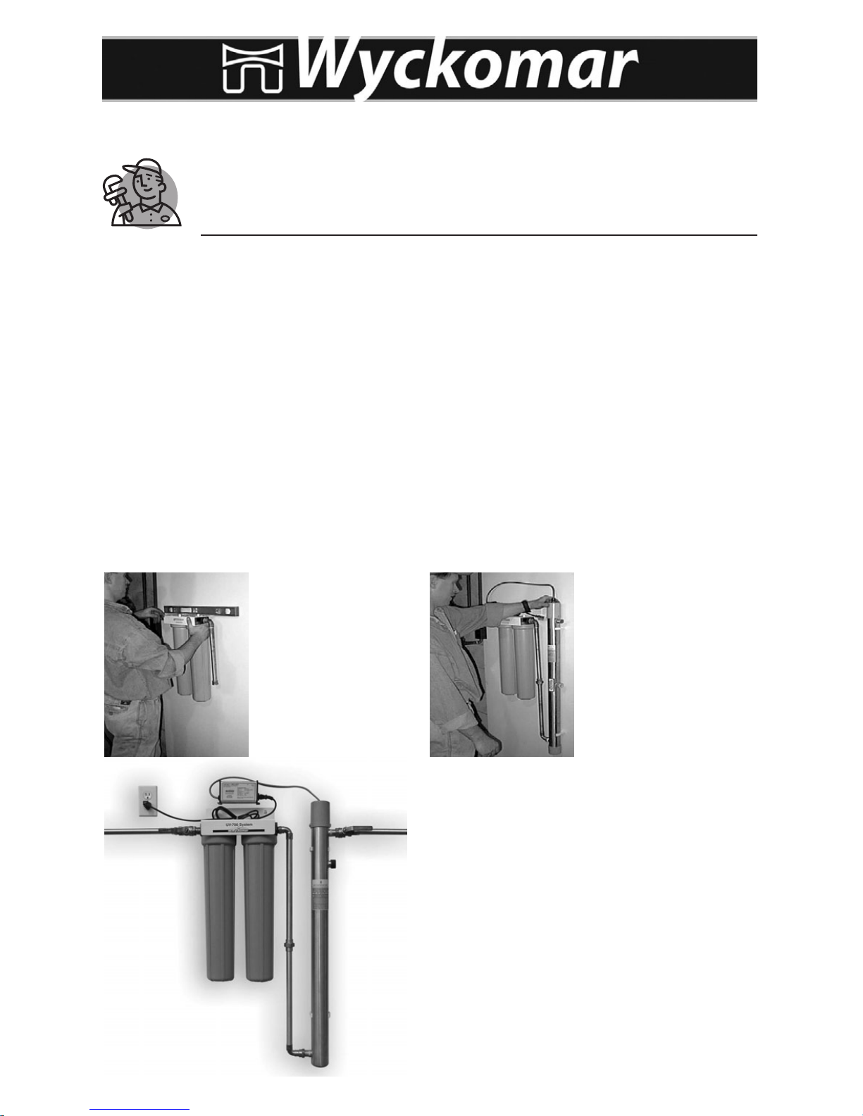
Turn off the main water supply valve. Fasten unit to wall, using the mounting clips
(”pipe hangers”) and screws provided. Press the UV chamber into the clips for a
secure hold.
Install new plumbing, making sure the In and Out ports on the lter set point in
the direction of water ow. Installation of bypass and valves is recommended.
Install lter set Install UV unit
Complete installation with pre-lter set and UV.
Inlet/Outlet shutoff valves are recommended.
After installation of the plumbing is
complete, install electrical components
(surge suppressor and ballast, monitor if
present) ABOVE the water line.
UV Purication Systems
8
Take the plastic cap off the unit and remove the black nut from the end of the
unit. Remove quartz sleeve/dome from packaging, being careful not to loose the
spring inside the dome. You may wish to lubricate o-ring with food-grade silicon
or plumber’s grease (do NOT use oil based products such as Vaseline) and roll it
over one end of the sleeve or the open end of the dome. Avoid ngerprints on the
sleeve/dome, wipe with alcohol.
Gently slide the sleeve/dome into the unit. For domed systems (UV-1, UV-250,
UV-700 and UV-1200), the dome will center itself inside the bottom of the reaction chamber. For sleeved systems (UV-1500, UV-3000, UV-5000 and UV-6000),
the sleeve(s) will protrude out of the reaction chamber at the bottom end, hold in
place with hand or foot. Roll second o-ring over the end at the bottom.
Thread on the compression nut(s). The O-ring will set itself into the beveled seal
of the bushing on the reaction chamber. Hand tighten the nut(s) (do NOT use
tools). In sleeved systems, install the lower plastic cap and gently tighten the set
screws with the Allen key supplied. This will keep the lamp from sliding through.
Insert the UV lamp, it will center itself in the spring inside the dome in domed systems, or stop at the lower plastic cap in sleeved systems. Connect the white 4-pin
electrical connector. Replace the top plastic cap and gently tighten setscrews.
Unit is now ready to be turned on.
Open main water valve slowly. As water lls into the lter set, press the red but-
ton on top of the rst lter housing (pressure relief valve) to release air. Hold until
water starts to escape and then release. Continue with next lter. Open valves
on either side of purier slowly and check for leaks (bypass valve should remain
closed). Turn on any faucet to release air in the system, wait for a steady stream
of water, then turn off faucet.
Plug the power cable from the ballast into an appropriate power source outlet (a
power surge suppressor rated at> 3600 Joules is strongly recommended). Wait for the lamp to come on (up to 30 sec) and inspect the ballast and
viewport, if present.
Now that system is operating properly, any incoming water is disinfected. Any ex-
isiting pathogens downstream of the system, if present, are not affected. Therefore, it is mandatory to disinfected the plumbing system downstream
from the unit after installation according to the instructions on Page 9.
Setting Up
Installation and Start Up Operation
 Loading...