

Wybron Coloram II, 19000, 19012, 19060 Power Supply User Manual
Power Supply User Manual

19000 – 24-Way Coloram Power Supply (600 watts)
19012 – 12-Way Coloram Power Supply (300 watts)
19060 – 6-Way Coloram Power Supply (150 watts)
Software versions: PS24 V3.0, PS12 V3.0, PS6 V3.0
Manual revision: April 14, 2003
CONTENTS
Safety Information................................................................ 3
Introduction...........................................................................4
The Coloram II System......................................................... 4
The Coloram II System Components ................................... 5
Color Changers and Other Components.............… .... .. 5
Power Supply.......................................................... .... .. 6
Cables..................................................................... .... .. 6
The Coloram II Power Supply Menu............................. .... .. 7
Menu Tree............................................................... .... .. 7
Menu Details........................................................... .... .. 7
Error Messages....................................................... .... .. 8
Installing/Connecting the Coloram II Power Supply............ 15
Head-Feet Restrictions....................................................... 17
Mounting and Installation Accessories ............................... 18
Equipment Compatibility..................................................... 21
Cables................................................................................ 21
Specifications ..................................................................... 22
Software Version Changes ................................................ 23
Parts list ............................................................................. 23
Warranty information.......................................................... 25
2

SAVE THESE INSTRUCTIONS
READ AND FOLLOW ALL
INSTRUCTIONS
IMPORTANT SAFETY INSTRUCTIONS
This manual gives step-by-step instructions for
preparation, setup and operation of the Coloram II Power
Supply.
There is a potential risk of fire, electric shock or injury to
persons if the product is not used as instructed.
This product is to be used in an indoor environment only
and is not intended for residential use.
3

Introduction
The Coloram II System consists of scrolling color changers, mixing color changers,
dowsers, other products and power supplies in a wide range of models offering ease of
setup and use. Its color changing capability and DMX compatibility affords the designer
wide capability and versatility. The lightweight color changers slide easily into the gel
frame holder of the light fixture. The compact power supplies attach easily to the truss of
the lighting rig or mount into a 19-inch rack.
The Coloram II System
The Coloram II System consists of one or more Color Changers or other components
and a remote power supply. The DMX512 control signal from the lighting board is
connected to the power supply and can continue on to more Coloram II Power Supplies
or other DMX-controlled devices. The power supply sends both power and control
signal on a single cable eliminating the need for a separate power cable for each color
changer.
The Coloram II System also allows you to control the color changer fan speed via one
or multiple DMX channels on the lighting console.
The Coloram II System is equipped with the Intelligent Diagnostic System (IDS). Status
information is sent from each of the Coloram II Color Changers to the Coloram II Power
Supply.
Caution: The Coloram II System is not compatible with the Forerunner
System. Do not connect Coloram II Color Changers to Forerunner Power
Supplies, or Forerunner Color Changers to Coloram II Power Supplies.
Damage from such action will not be covered by the Coloram II or
Forerunner warranties.
4
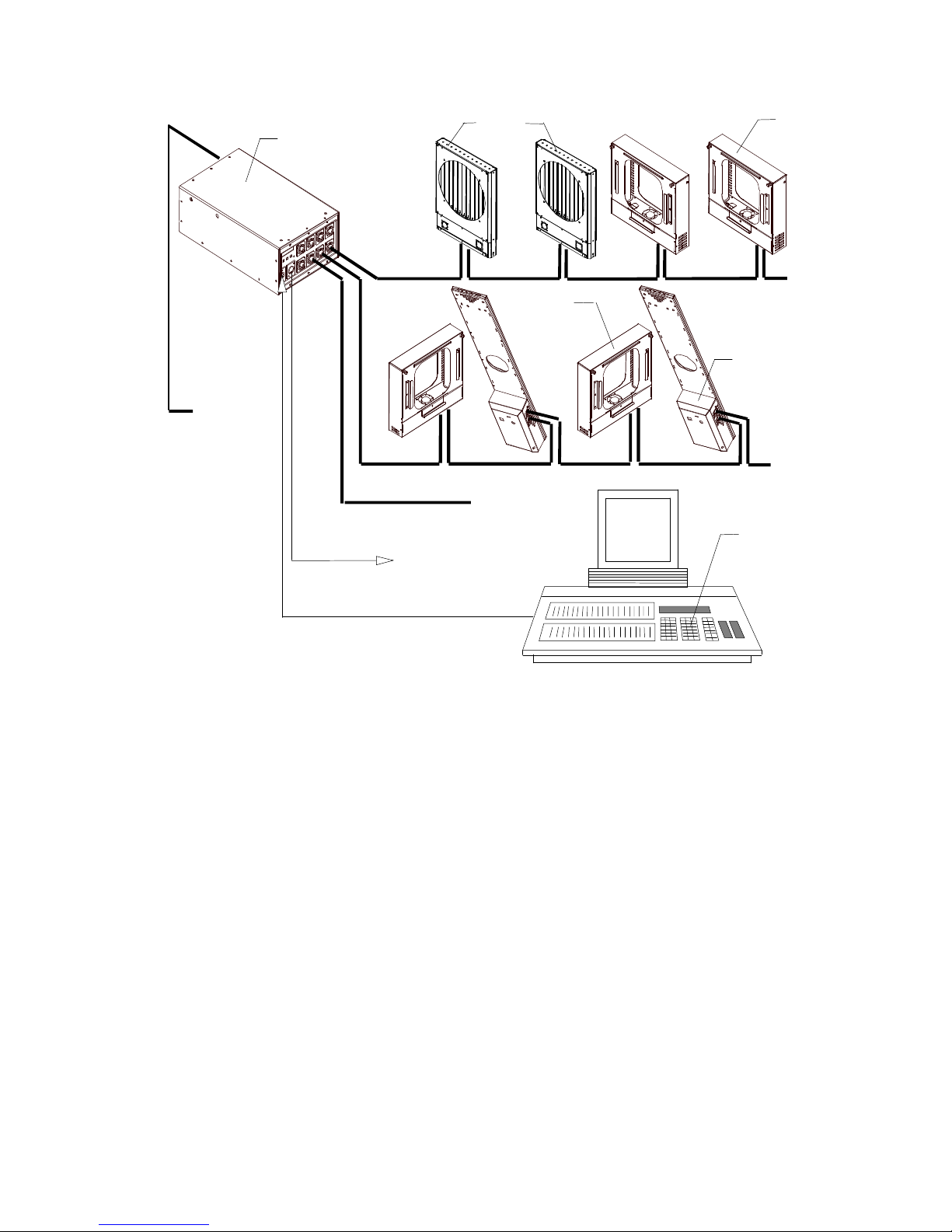
AC Power
Coloram II
Coloram II
Power Supply
Buffered
DMX512
Eclipse
Dowser
Coloram II
Color Changer
To additional
Color Changers
or Gobo Changers
To additional
Coloram Power Supplies
DMX512
Color Changer
To additional
Color Changers
or Gobo Chgrs
Goboram II Gobo Chgr
To additional
Color Changers
or Gobo Chgrs
DMX Control console
DMX CONSOLE
The Coloram II System Components
Color changers and other components
The color changers set the position of the gelstring via a signal from the lighting
console. The control signal and DC power (24 VDC) are both supplied in one cable
connecting the color changers to the power supply.
Other Coloram II products include the Eclipse Dowser, the CXI Color Changer and
others. Other products are continually being added to the Coloram II family to expand its
capabilities.
Refer to the user manual of the various Coloram II products for detailed operating
information on those products.
5
Power Supply
The power supply converts the DMX512 signal level from the lighting console into
Coloram I/Coloram II control signal which it then sends to each color changer along with
24 volts DC. The power supply features a DMX bypass relay to pass the DMX signal to
the DMX output connector in the event of AC power loss.
The power supply features an 8 character LED display and three selector buttons. This
user interface is used to select the starting DMX channel, set operating modes, send
remote commands to the color changers and view color changer status.
Coloram II Cable
The Coloram II Cable connects the Coloram II Power Supply outputs to the Coloram II
Color Changers or other products and provides them with power and control signal. The
Coloram II Cable uses 4-pin XLR connectors on either end and consists of two 14 AWG
conductors and a 22 AWG twisted, shielded pair.
Note: Colroam II Cable is used in the Coloram II System and in the Forerunner System.
It may be referred to as either Coloram cable or Forerunner cable.
The Coloram II Power Supply menu
This section describes the power supply menu.
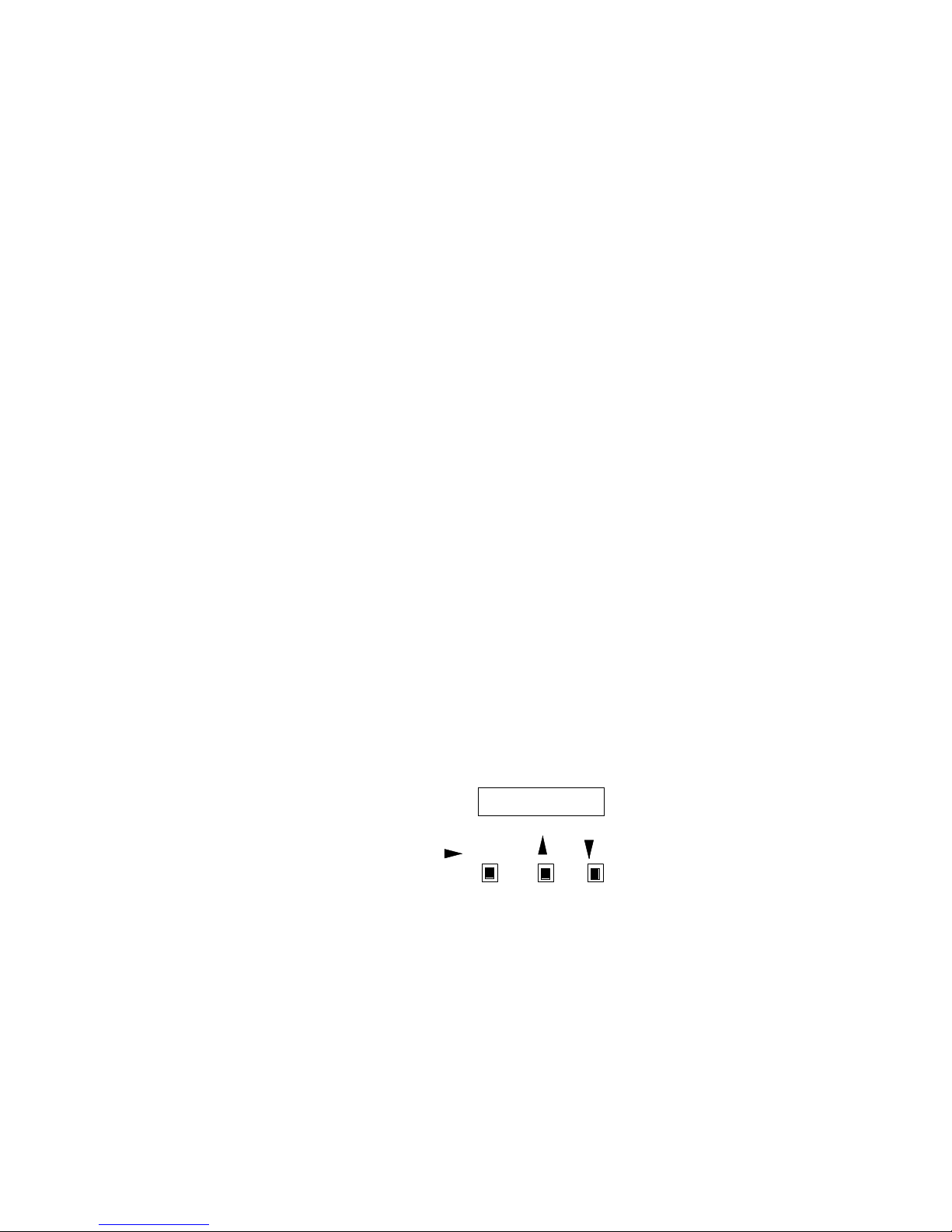
The following diagram is the eight character display and the three push buttons:
DISPLAY
/ENTER
The following diagram is an overall view of the power supply menu structure:
+
_
6
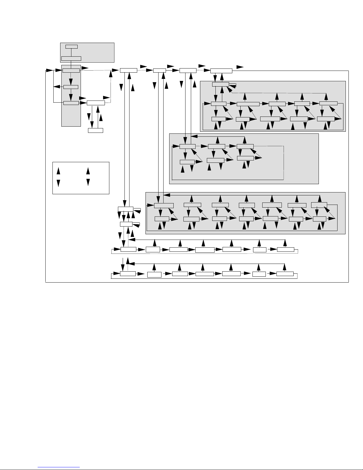
INTRO
ROLLCALL
1 -- X
" "
POWER-UP
SCREENS
XX UNITS
" "
SETUP
" "
OPTIONS
" "
COMMANDS
" "
DMX OK
*ALERT*
RUN
SCREEN
LOOP
" "
MEANS PRESS
" "
MEANS PRESS
" "
" " " "
ALERT DETAILS
APPEAR HERE
X ALERT
BUTTON
BUTTON
" "
" "
DMX 001
" "
1 OF 1
" "
Coloram
" "
Increment
" "
Increment
" "
DMX
1 of X
" "
Chan 001
CHAN ?
+
" "
" "
" "
Disp %
DISP ?
DEC
%
HEX
Mode CR2
MODE ?
CR1
-
POS 000DCV 24
DMX ALL
Re-Init POS 000
SEND ?
YES
Run REG
Run ? xxx
REG
MIN
Tbck OFF Jttr OFF
TBCK ?
ON
CR2
Fan NORM
INCREMENT
DMX
SHUTDOWN
SEND ? POS ? XXX
YES
NO
Reset NO
RESET ?
OK
JTTR ?
ON
OFF
Mtr NORM
NO
NO
OFF
Ver x.x
+
-
DMXF OFF
DMXF ?
OFF
ONE
BLK
FChn XXX
IDENTIFY
Fan LOW
Fan? LOW
NORM
LOW
OFF
NO DMX
PROCESSING
FChn ?
-
+
Mtr NORM
Mtr ? LOW
NORM
Foff OFF
Foff ?
ON
NO DMX
PROCESSING
LOW
NO DMX
PROCESSING
OFF
OR ...
CXI
DCV 24
GLA 0%
GLB 0%
Fan NORM
Ver x.x
IDENTIFY
Menu Details
The following is an explanation of functions and optional settings which are accessed
via the various menus displayed.
POWER UP SCREENS
When you connect the power supply to AC power, the following screens will appear on
the display.
1. The INTRODUCTION screen will scroll through the software version and
other information.
2. The ROLLCALL screen shows when the power supply interrogates the
color changers and other components connected to the power supply. This is the
time the color changers "check in" with the power supply.
7

RUN SCREEN LOOP
The display alternates between three screens.
The first is "1 -- X" where X is highest DMX channel used by a color changer (or other
component) connected to the power supply. If talkback is ON, X will be the highest DMX
channel used by the talkback function.
The second screen is "DMX OK" if the DMX signal is being properly received. It is
"NO DMX” if the DMX signal is not being properly received.
The third screen is " *ALERTS* " if there are any alert conditions to report.
ALERTS / ERROR MESSAGES
The power supply will display "alert messages" indicating a condition a service person
may want to know about.
The alert messages and meanings are as follows:
Note: the "xxx" after each message is the DMX channel to which the message applies.
"Pstn xxx" - Gel position error - a difference exists between the commanded gel
position and the actual gel position.
"VDC xxx" - Color changer voltage is below 17 volts DC.
"Shut xxx" - Color changer reports a SHUTDOWN condition (will not respond to
position commands because the voltage dropped below 15 VDC).
"Drop xxx" - Color changer is disconnected and there is a loss of communication - it
previously reported a status but is no longer doing so.
"Motr xxx" - The color changer's motor cannot move the gel string.
"ChErr xxx" - There is a channel assignment problem with the color changer set to start
on channel xxx. For example, some of the multiple channels used by the
color changer fall past the last channel available on the power supply.
"Overload" - This is displayed when the power supply has not yet reached its current
limit, a unit "checks in" which has a current requirement at least 2 times
that of a Coloram II and the resulting total current load on the power
supply is over the power supply's limit. This last unit will remain checked
in. However, no more units will be allowed to check in.
8
 Loading...