

Wyatt Technology Optilab rEX User Manual

Optilab rEX
User’s Guide
(M1500 Rev. F)

WYATT TECHNOLOGY Corporation makes no warranties, either express or implied,
regarding this instrument, computer software package, its merchantability or its fitness
for any particular purpose. The software is provided “as is”, without warranty of any
kind. Furthermore, Wyatt Technology does not warrant, guarantee, or make any representations regarding the use, or the results of the use, of the software or written materials in terms of correctness, accuracy, reliability, currentness, or otherwise. The exclusion
of implied warranties is not permitted by some states, so the above exclusion may not
apply to you.
Copyright © 2008, Wyatt Technology Corporation. All rights reserved.
All rights reserved. No part of this publication may be reproduced, stored in a retrieval
system, or transmitted, in any form by any means, electronic, mechanical, photocopying,
recording, or otherwise, without the prior written permission of Wyatt Technology Corporation.
® DAWN, ASTRA, DNDC, and Optilab are registered trademarks of Wyatt Technology
Corporation.
A variety of U.S. and foreign patents have been issued and/or are pending on various
aspects of the apparatus and methodology implemented by this instrumentation.

Contents
Chapter 1: About the Optilab rEX ........................................... 1-1
1.1 Methods of Measuring Refractive Indexes ..................................................1-2
1.2 Using This Manual ...................................................................................... 1-3
1.3 Contacting Wyatt Technology ........................................................ .............. 1-4
Chapter 2: Instrume n t De scr ipt i o n ......... .. ... .. ......................... 2-1
2.1 Overview .. ................................................................................................... 2 -2
2.2 Front Pan el .................................................................................................. 2-3
2.3 Rear Panel .................................................................................................. 2-4
Chapter 3: Quick Start.............................................................. 3-1
3.1 Setting Up the Optilab rEX .......................................................................... 3-2
Chapter 4: Installation and Set up ......................... ... .. ............. 4-1
4.1 Power and Signal Connections ...................................................................4-2
4.1.1 Power Connector ............................................................................................4-2
4.1.2 Signal Connectors ...........................................................................................4-2
4.1.3 Communication Connector ..............................................................................4-7
4.2 Fluid Connections ....................................................................................... 4-7
4.3 Dry Nitrogen Connection ............................................................................. 4-8
4.4 Power On and Warm Up .............................. .. .. ...........................................4-9
4.5 Purging the Optilab rEX .............................................................................. 4-9
4.6 Instrume n t Stability Check .................... .............................................. ....... 4-10
Chapter 5: Using the LCD Disp l ay........................... .. ............. 5-1
5.1 Navigatin g th e Opt ila b rE X Tabs ..... ... ......................................................... 5-2
5.2 Main Tab ... ........................ .............................................. ............................. 5-3
5.3 aRI Tab ........................................................................................................5-4
5.4 Alarms Tab ..................... .................................................................... ......... 5-5
5.5 System Tab ........... ...................................................................................... 5-7
5.5.1 Constants Dialog .............................................................................................5-9
5.5.2 LED Intensity Dialog ......................................................................................5-11
5.6 Communic a ti o ns Tab ................... ........................ ...................................... 5-13
Chapter 6: Off-Line Measurements........................ ................. 6-1
6.1 Instrument Calibration for dRI .....................................................................6-2
6.1.1 General Information and Sample Preparation .................................................6-2
6.1.2 HPLC Pump with Injector ................................................................................6-3
6.1.3 Syringe Pump Infusion ....................................................................................6-3
6.1.4 Collecting Data for Optilab rEX dRI Calibration ..............................................6-4
Optilab rEX User’s Guide (M1500 Rev. F) iii

Contents
6.2 dn/dc Me a s u re me n t ......................................................... ...........................6-6
6.3 Instrument Calibration for aRI .....................................................................6-7
6.3.1 General Information ........................................................................................6-7
6.3.2 Collecting Data for Optilab rEX aRI Calibration ..............................................6-7
6.4 Absolute Refractive Index Measurement ..................................................6-10
Chapter 7: In-Line HPLC Detection......................................... 7-1
7.1 Condition s fo r In - L in e Ope ration ... .............................................................. 7-2
7.2 Sample Pre para tio n ......... .. .............................................. ...........................7-3
7.3 Measurem e n t . .. ..................................................................... ...................... 7-3
Chapter 8: Service and Ma intenance........ ... .. ......................... 8-1
8.1 Replacing the LED/Fiber Light Source ........................................................8-2
8.2 Cleaning After a Fluid Leak .................................... ....................................8-11
8.3 Cleaning the Air Intake Filter .................................. ...................................8-12
8.4 Changing a Fus e ....................................................................................... 8 -1 2
8.5 Optilab rEX Firmware Upgrades ................................... ............................8-13
Chapter 9: Troubleshooting . .. ... .......................... .. ... ............... 9-1
9.1 Low Light Ala rm ........ .. ................................................................................ 9-2
9.2 Tempera ture Will Not Set Below 20 C ............... ........................ .................. 9-3
9.3 Noisy Base lin e ............ ......................... ....................................................... 9 -4
9.4 Microsoft Windows Encounters Problems ................... .. .............................. 9-4
Appendix A: Acronyms and Abbreviations List................... A-1
A.1 Acronyms and Abbreviations .................... .. ........................................... .. .. .A-2
Appendix B: Operating Principles and Theory..................... B-1
B.1 Basic Prin c ip le s ............. .. ........................ ...................................................B-2
B.1.1 Conventional Flow Cell ................................................................................. B-2
B.1.2 Optilab rEX Flow Cell ..................................................................................... B-3
B.2 Measure me n t o f th e Bea m D e fl e ct io n A ng l e .. ............................................B-4
B.2.1 Conventional Split Photodiode Based Instrument ........................................ B-4
B.2.2 Wyatt Technology Corporation Beam Positioning Technology ......................B-4
Appendix C: Optilab rEX Specifications ............................... C-1
C.1 Specifications ................................................... ..........................................C-2
Appendix D: Wire Colors........................................................ D-1
D.1 Earlier Cab le Re v is io n s ..................... .. .......................................................D-2
Appendix E: Instrument Connectivity ................................... E-1
E.1 Introduction .................................................................................................E -2
iv Optilab rEX User’s Guide (M1500 Rev. F)

Contents
E.2 Components Used ......................................................................................E-3
E.2.1 Instrument Connections ........................................ ......................................... E-3
E.2.2 LAN Connection ....... ....... ...... ....... ...... ....... ...... ............................................... E-4
E.2.3 Computer Connections ................ ...... ....... ...... ...... ......................................... E-4
E.2.4 Crossover Cable ................... ....... ...... ....... ...... ...... ....... ...... ....... ...... ....... ...... .. E-5
E.2.5 Ethernet Cable ................................................ ...... ....... ...... ....... ...... ....... ...... .. E-5
E.2.6 Ethernet to USB Adapter ............................................................................... E-6
E.2.7 Ethernet Switch .............................................................................................. E-7
E.3 Connecting to a LAN ...................................................................................E-8
E.3.1 One Instrument to LAN ............................. ..................................................... E - 8
E.3.2 One Instrument and Computer to LAN ........................ ...... ....... ...... ....... ...... .. E-9
E.3.3 Multiple Instruments to LAN ......... ...... ....... ................................................... E -1 0
E.3.4 Multiple Instruments and Computer to LAN .............................. ...... ....... ...... . E -11
E.4 Connectin g via U SB ...................... ............................................................E-12
E.4.1 One Instrument to USB via a Crossover Cable ........................................... E-12
E.4.2 One Instrument to USB Using an Ethernet Switch ......................................E-13
E.4.3 Multiple Instruments to USB .............. ....... ................................................... E-1 4
E.5 Connecti ng via E th e rn e t W h en N o t o n a LAN ........... ...................... .. .. .....E-15
E.5.1 One Instrument to Computer Using Crossover Cable .................................E-15
E.5.2 One Instrument to Computer Using an Ethernet Switch .............................. E-16
E.5.3 Multiple Instruments to Computer Using an Ethernet Switch ...................... E-16
E.6 Instrume n t Ne tw o r k S e ttings .....................................................................E-17
E.7 Accessin g In st ru ments with ASTRA V ................................ .. ....................E-1 8
E.8 Troubleshooting and Diagnostics .............................................................E-19
E.8.1 Windows XP Professional Service Pack 2 ................................................... E-19
E.8.2 ASTRA V Settings .......................................................................................E-19
E.8.3 Verifying Instrument Connections ......................... ....... ...... ....... ...... ....... ...... E-19
Appendix F: Warnings ............................................................. F-1
F.1 List of Warnings ........................................................................................... F-2
Index .................................................................................. Index-1
Optilab rEX User’s Guide (M1500 Rev. F) v

vi Optilab rEX User’s Guide (M1500 Rev. F)

1
About the Optilab rEX
This chapter provides a general introduction to the Optilab rEX instrument and an overview of the sections in this manual.
CONTENTS PAGE
1.1 Methods of Measuring Refractive Indexes..................................... 1-2
1.2 Using This Manual.......................................................................... 1-3
1.3 Contacting Wyatt Technology......................................................... 1-4
Optilab rEX User’s Guide (M1500 Rev. F) 1-1

Chapter 1: About the Optilab rEX
1.1 Methods of Measuring Refractive Indexes
For the past four decades, virtually all differential Refractive Index (dRI)
detector manufacturers have used a deflection-based instrument design to
measure the refractive index difference between a reference fluid and a
sample fluid. Wyatt Technology’s Optilab DSP stood alone as an interferometric-based instrument with the ability to cool samples below ambient
temperatures. When the Optilab DSP was introduced, an interferometricbased design was the most sensitive method available for measuring dRI.
However, technology does not remain motionless. Significant advances
over the past five years in nanoscale semiconductor fabrication techniques, linear photodiode array technology, and computer speed have
allowed Wyatt Technology to develop a novel deflection-based dRI instrument that surpasses all current measurement methods.
The Optilab rEX (refractometer with EXtended range) is a deflectionbased instrument that pioneers the use of an array of light sensitive detectors in the measurement of dRI. It has a linear array of 512 photodiodes,
rather than the traditional two photodiodes used by other deflection-based
instruments. This photodiode array allows for unprecedented sensitivity
and range.
With most RI instruments, users must choose a gain setting, which essentially means choosing between good sensitivity over a limited range,
reduced sensitivity over a large range, or some compromise between the
two. The Optilab rEX has no gain settings; the maximum sensitivity exists
over the entire range. Tiny signals and huge signals may be measured
within the same data run. The ability to see both large and small signals
may be quantified by the instrument’s dynamic range (defined as range
divided by noise). The dynamic range of the Optilab rEX is 2.35 million,
literally orders of magnitude greater than any other RI instrument on the
market today.
In addition to the photodiode array, the Optilab rEX contains a new flow
cell design that allows the measurement of a fluid’s absolute Refractive
Index (aRI) in addition to the dRI between two fluids. The aRI of a fluid is
vital for characterizing a system and is a necessary input parameter for
light scattering measurements that determine the molecular mass of molecules in solution.
1-2 Optilab rEX User’s Guide (M1500 Rev. F)

1.2 Using This Manual
The organization of this manual is as follows:
• Chapter 2, “Instrument Description”: Describes the Optilab rEX
instrument’s control interfaces and connections.
• Chapter 3, “Quick Start”: Contains a summary of instructions for
setting up the Optilab rEX quickly and with minimal instruction.
• Chapter 4, “Installation and Setup”: Provides detailed connection
information for installation and setup.
• Chapter 5, “Using the LCD Display”: Provides detailed information
on how to use the tabs on the LCD display to control, configure, and
monitor the Optilab rEX.
• Chapter 6, “Off-Line Measurements”: Describes how to make
static measurements with the Optilab rEX, including instrument calibration, off-line dn/dc measurements, and absolute refractive index
measurements.
• Chapter 7, “In-Line HPLC Detection”: Describes using the Optilab
rEX as an in-line concentration sensitive detector for HPLC.
Using This Manual
• Chapter 8, “Service and Maintenance”: Provides maintenance and
service instructions.
• Chapter 9, “Troubleshooting”: Provides troubleshooting tips.
• Appendix A, “Acronyms and Abbreviations List”: Contains a list
of acronyms and abbreviations used in this manual.
• Appendix B, “Operating Principles and Theory”: Provides a basic
and theoretical description of how the Optilab rEX operates.
• Appendix C, “Optilab rEX Specifications”: Provides the specifica-
tions of the Optilab rEX.
• Appendix D, “Wire Colors”: Provides information about earlier revi-
sions of the general-purpose cable supplied by Wyatt Technology
Corporation.
• Appendix E, “Instrument Connectivity”: Provides details about
connecting the Optilab rEX to a computer.
• Appendix F, “Warnings”: Lists warnings to be aware of when using
the Optilab rEX.
• Index: Provides lookup assistance.
Optilab rEX User’s Guide (M1500 Rev. F) 1-3

Chapter 1: About the Optilab rEX
1.3 Contacting Wyatt Technology
We solicit and encourage questions and comments about this manual and
the Optilab rEX instrument. Please contact:
Technical Support Department
Wyatt Technology Corporation
6300 Hollister Avenue
Santa Barbara, CA 93117
Telephone: (805) 681-9009
FAX: (805) 681-0123
E-mail: support@wyatt.com
1-4 Optilab rEX User’s Guide (M1500 Rev. F)

2
Instrument Description
This chapter provides an overview of the Optilab rEX features.
CONTENTS PAGE
2.1 Overview......................................................................................... 2-2
2.2 Front Panel..................................................................................... 2-3
2.3 Rear Panel......................................................................................2-4
Optilab rEX User’s Guide (M1500 Rev. F) 2-1

Chapter 2: Instrument Description
2.1 Overview
The Optilab rEX measures the dRI between the current liquid sample
stream and a liquid (usually clean solvent) previously stored as a reference. The dRI is measured at a fixed wavelength determined by a Light
Emitting Diode (LED)/fiber light source. The light source consists of a
high-powered LED coupled to a special optical fiber. This “pigtail” configuration allows you to easily replace the light source. If you want to change
the measurement wavelength, installing a “pigtail” with a different wavelength accomplishes this.
The dRI data can be read from the LCD display, the analog output
channel, or digitally through the Ethernet port. Since the dRI of liquids
depends critically on temperature, the instrument has a system that precisely regulates the temperature of both the flow cell and the optics.
In addition to the dRI between two liquids, with the same liquid present in
the sample and reference chambers, the Optilab rEX measures the aRI of
that liquid.
For a more detailed theoretical description, see Appendix B, “Operating
Principles and Theory”.
2-2 Optilab rEX User’s Guide (M1500 Rev. F)
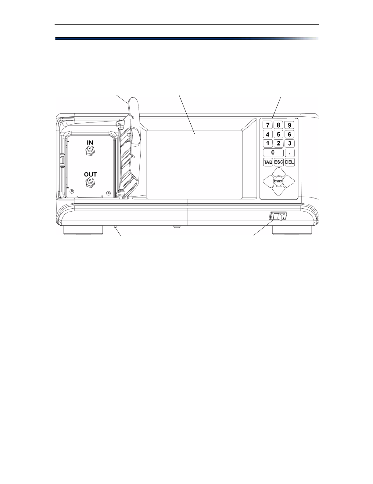
2.2 Front Panel
The front panel, see Figure 2-1, provides fluid connections for the Optilab
rEX and all of the necessary functions and displays for operating the
instrument and monitoring data.
Front Panel
Front Panel Door LCD Display
Liquid Leak Port
Figure 2-1: Front panel
Power Switch
Keypad
Front Panel Door: The front panel door opens to provide access to the IN
and OUT fluid connections for the Optilab rEX.
LCD Display: The LCD display provides a full-color, high-resolution user
interface to the Optilab rEX. It allows you to monitor, control and configure the instrument. Chapter 5, “Using the LCD Display” describes all
of the tabs available on the LCD display and their functions.
Keypad: The keypad allows you to control the LCD display. “Navigating
the Optilab rEX Tabs” on page 5-2 describes how to use the keypad to
navigate through the LCD display tabs.
IN/OUT Fluid Connectors: Fluid comes into the Optilab rEX through
the IN port, and exits through the OUT port. The Optilab rEX should be
connected last in line if other detectors are connected in series.
Liquid Leak Port: The liquid leak port provides an exit for any liquid
that leaks from internal or external fittings. The Teflon tubing provided
may be fit over this tubing and directed to a fluid waste bottle. When a
liquid leak occurs, an internal liquid sensor activates an alarm shown on
the LCD display (see “Alarms Tab” on page 5-5), and activates an Alarm
Out signal that may be used to shut off a pump.
Power Switch: The power switch turns instrument power On and Off.
Optilab rEX User’s Guide (M1500 Rev. F) 2-3
Chapter 2: Instrument Description
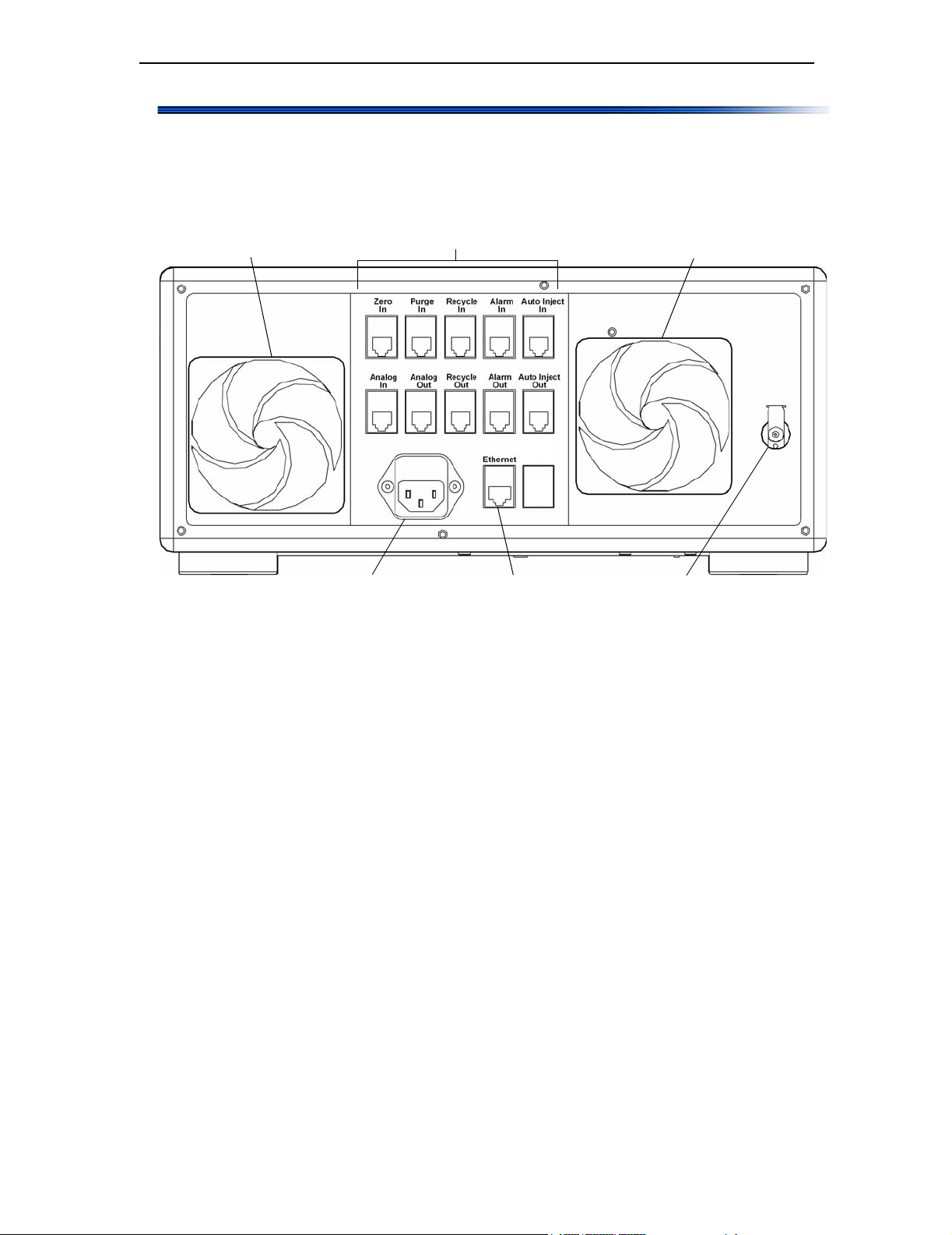
2.3 Rear Panel
The rear panel, see Figure 2-2, provides access for power, signal connections, the cooling fan, air filter, the exhaust fan, and a nitrogen purge port.
Air Intake Fan
Power Connector
Air Intake and Exhaust Fans: The fans help to keep the instrument
electronics at a constant temperature.
Signal Connectors
Communications Connector
Figure 2-2: Rear panel
Air Exhaust Fan
Nitrogen Purge Port
Signal Connectors: There are 10 RJ-12 connectors that provide connections to Transistor-Transistor Logic (TTL) inputs and outputs, Analog
input and output, Auto Inject input and output, and a solenoid drive
output. For a description of the signal connectors, see “Power and Signal
Connections” on page 4-2.
Power Connector: Provides power to the instrument. See “Power and
Signal Connections” on page 4-2 for a complete description of the Optilab
rEX’s power requirements.
Communications Connector: The Ethernet connector allows you to
connect to a computer or an Ethernet network.
Nitrogen Purge Port: Provides the connection to purge the instrument
with dry nitrogen in order to prevent condensation on the optical and measurement systems. For detailed information regarding the nitrogen purge
port, see “Dry Nitrogen Connection” on page 4-8.
2-4 Optilab rEX User’s Guide (M1500 Rev. F)

3
Quick Start
This chapter provides rudimentary setup procedures for first-time or experienced users who want to start the Optilab rEX installation process
before reading the entire manual.
Detailed descriptions and important use instructions concerning the
Optilab rEX are provided in the chapters that follow.
CONTENTS PAGE
3.1 Setting Up the Optilab rEX ............................................................. 3-2
Optilab rEX User’s Guide (M1500 Rev. F) 3-1

Chapter 3: Quick Start
3.1 Setting Up the Optilab rEX
This section describes basic setup procedures for those who want to begin
using the Optilab rEX as soon as possible.
More details about setting up the Optilab rEX are provided in Chapter 4,
“Installation and Setup”. (You may notice that the setup sequence in
this chapter differs a bit from that in Chapter 4. The sequence in this
chapter allows you to begin stabilizing the temperature earlier in the
sequence.)
See Chapter 2, “Instrument Description” for descriptions of the front
and rear panel controls and connections.
For instructions on navigating the LCD display tabs, see “Navigating the
Optilab rEX Tabs” on page 5-2.
Note: The Optilab rEX can be safely stacked above and below other instruments.
1. Connect the power cable. The power outlet is located on the Optilab
rEX rear panel (see Figure 2-2). The power supply is universal, for
immediate use with 100–120 V or 220–240 V power at 50-60 Hz. (See
also “Power and Signal Connections” on page 4-2.)
2. Power ON the Optilab rEX. Time to full warm-up is approximately
30 minutes. (See also “Power On and Warm Up” on page 4-9.)
3. Set temperature. The Optilab rEX default temperature is 25°C, with
a range of 4°C to 50°C. (If you are operating below 25°C, it is important
that you see “Dry Nitrogen Connection” on page 4-8 before cooling the
instrument.)
4. Make fluid connections. Standard HPLC fittings: 1/16 in. OD tubing, 10-32 threads. The Optilab rEX should be connected last in line if
other detectors are to be connected in series. (See also “Fluid Connections” on page 4-7.) The IN and OUT ports are located behind a door on
the front panel (see Figure 2-1).
Tubing recommendations are:
• 0.010 in. (0.254 mm) ID to the Optilab rEX IN port.
• 0.020 in. (0.508 mm) or larger ID from the Optilab rEX OUT port
to a waste bottle or solvent recycle valve.
5. Flush the Optilab rEX in purge mode. Use 20 mL of co-miscible
solvents stepwise as necessary to prepare the cell for data collection.
(See also “Purging the Optilab rEX” on page 4-9.) Tab to the Purge
On/Off button using the front panel arrow keys (see Figure 2-1).
3-2 Optilab rEX User’s Guide (M1500 Rev. F)

Setting Up the Optilab rEX
The Optilab rEX is shipped with Ethanol in the flow cell. A typical
series of solvents (from polar to nonpolar) is shown below. Salt solutions should be considered separate steps from pure solvents.
Water
Methanol, Ethanol
Isopropanol, Acetone
Tetrahydrofuran
Ethylacetate, Chloroform, Methylene chloride
Toluene, Carbon disulfide
Hexane, Petroleum ether
6. Zero the instrument. Activate the Zero selection on the Optilab rEX
LCD display. (See also “Main Tab” on page 5-3)
7. Install software.
a. For in-line use with chromatography, install ASTRA or equivalent
chromatography software. See the appropriate software manual
for installation instructions.
b. For off-line use (e.g., dn/dc determinations), install ASTRA V soft-
ware. See the appropriate software manual for installation instructions.
8. Connect communication cable. (See also “Power and Signal Connections” on page 4-2.)
a. If data is to be collected using the ASTRA V software, connect the
Optilab rEX directly to a computer or local area network (LAN)
using the Ethernet cable provided.
b. If data is to be collected using ASTRA 4.X, DNDC, or other soft-
ware, connect the Optilab rEX analog output to a DAWN or
miniDAWN instrument’s analog input AUX1 port using the analog
cable provided.
Optilab rEX User’s Guide (M1500 Rev. F) 3-3

Chapter 3: Quick Start
3-4 Optilab rEX User’s Guide (M1500 Rev. F)

4
Installation and Setup
This chapter describes the fluid, power, and signal connections used in
setting up the Optilab rEX.
CONTENTS PAGE
4.1 Power and Signal Connections...................................................... 4-2
4.1.1 Power Connector....................................................................... 4-2
4.1.2 Signal Connectors..................................................................... 4-2
4.1.3 Communication Connector........................................................ 4-7
4.2 Fluid Connections........................................................................... 4-7
4.3 Dry Nitrogen Connection ................................................................4-8
4.4 Power On and Warm Up ................................................................ 4-9
4.5 Purging the Optilab rEX.................................................................. 4-9
4.6 Instrument Stability Check.............................................................. 4-10
Optilab rEX User’s Guide (M1500 Rev. F) 4-1
Chapter 4: Installation and Setup
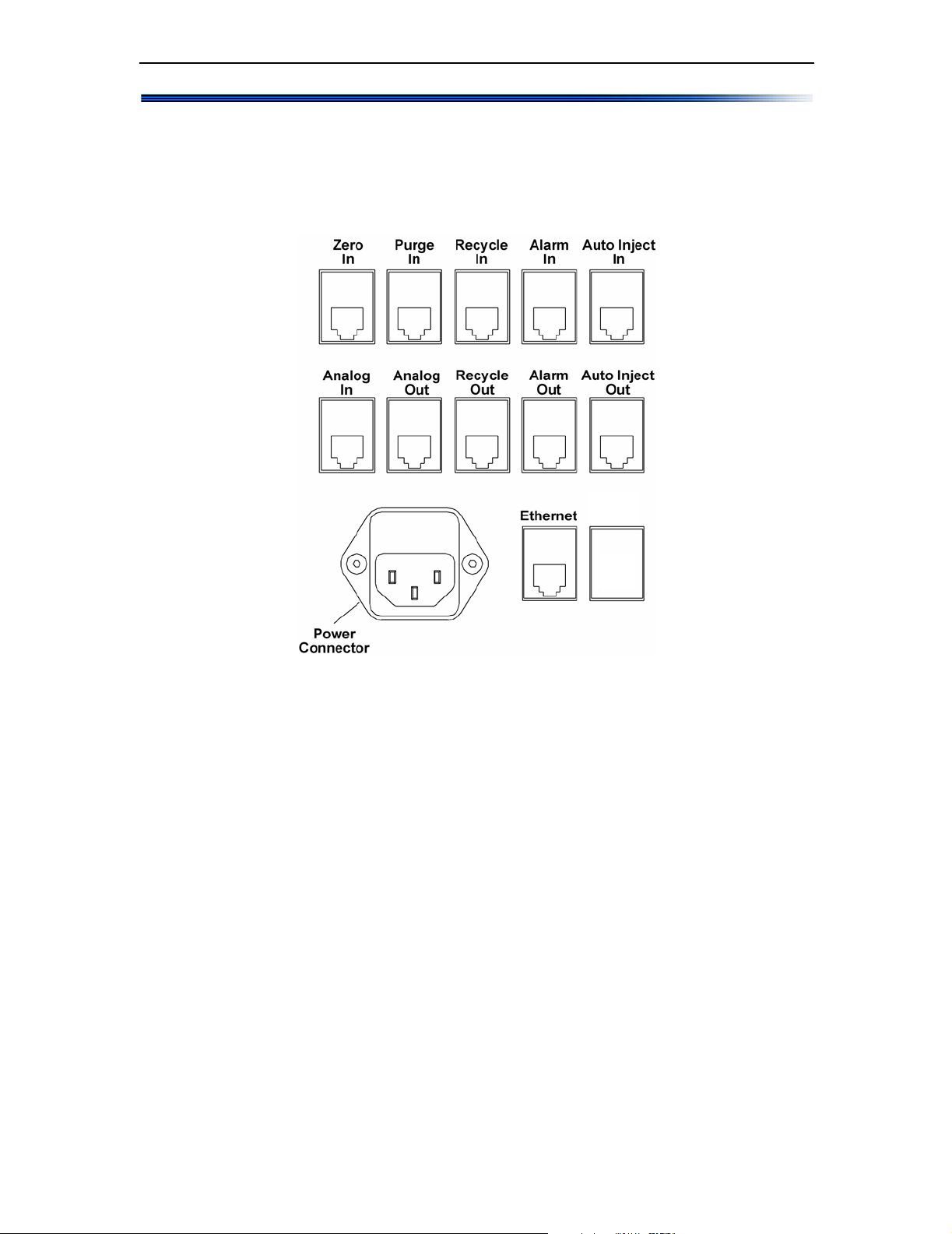
4.1 Power and Signal Connectio ns
All power and signal connections to the Optilab rEX are made using the
interfaces on the rear panel of the instrument. Refer to Figure 4-1 to view
the connectors on the rear panel of the Optilab rEX.
Figure 4-1: Rear panel power and signal connections
4.1.1 Power Connector
The power input accepts 100–250 VAC at 50–60 Hz. The power input
module contains two fuses, each rated at 2 Amps, one for the line voltage
in, and the other for the line voltage return.
4.1.2 Signal Connectors
The instrument rear panel contains 10 RJ-12 connectors for TTL inputs
and outputs, analog input and output, auto inject input and output, and a
solenoid drive output.
Cables not supplied by Wyatt Technology may use a different color code
scheme or have a different correspondence between color and pin number.
If you are using non-Wyatt Technology supplied cables, refer to Figure 4-2
and Table 4-1 to determine the correct pin number and wire usage. We
recommend using only cables supplied by Wyatt Technology; wiring the
connection incorrectly could damage your instrument.
Pinouts for the RJ-12 connectors used in Wyatt Technology-supplied
cables are shown in Figure 4-2.
4-2 Optilab rEX User’s Guide (M1500 Rev. F)
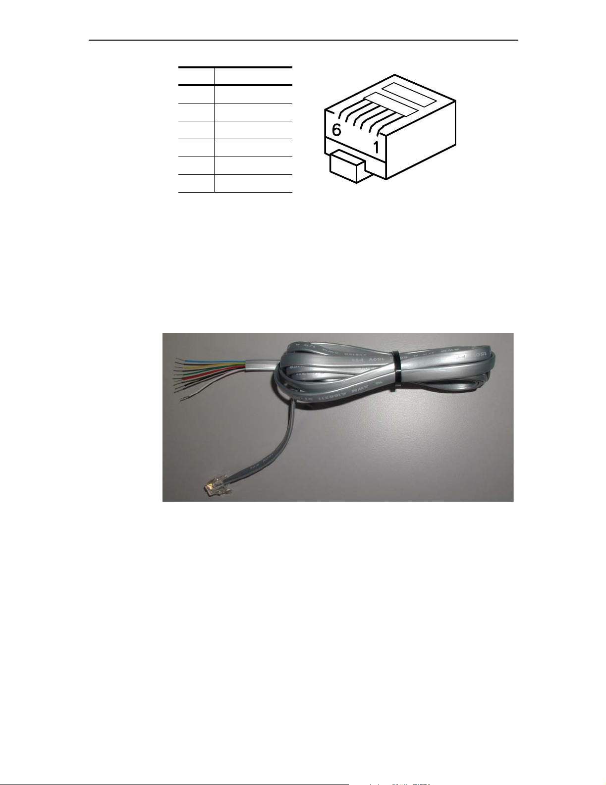
Power and Signal Connections
Pin Wire Color
1White
2Black
3Red
4Green
5Yellow
6Blue
Figure 4-2: RJ-12 Connector and Pinouts
Several general-purpose cables are supplied for TTL inputs and outputs,
analog inputs and outputs, auto inject input and output, and solenoid
drive output.
Earlier revisions of the general-purpose cables have different wire colors
than those listed in Figure 4-2. If your Wyatt Technology supplied generalpurpose cables do not have the same colors listed in Figure 4-2, refer to the
wire colors listed in Appendix D, “Wire Colors”.
Figure 4-3: General-purpose cable
An analog out cable is supplied to connect to the Optilab rEX analog
output to a DAWN or miniDAWN AUX analog input.
Optilab rEX User’s Guide (M1500 Rev. F) 4-3

Chapter 4: Installation and Setup
Figure 4-4: Analog Optilab rEX to DAWN or miniDAWN cable
When you connect your Optilab rEX to other instruments, see Table 4-1
for RJ-12 connector signal information.
Table 4-1: RJ-12 Signal Function
Optilab rEX
Connector
White Black Red Green Yellow Blue
Zero In Signal Signal
Purge In Signal Signal
Recycle In Signal Signal
Alarm In Signal Signal
Auto Inject In Signal Signal
Analog In Positive Negative Ground
Analog Out Positive Negative Ground
Recycle Out Signal Signal
Alarm Out Signal Signal
Auto Inject Out Contact Contact
RJ-12 Connector Wire Signal
Ground
Ground
Ground
Ground
Ground
Ground
Ground
The Zero In, Purge In, Recycle In, Alarm In, and Alarm Out signals all
follow the TTL voltage convention. In the TTL convention, 5 V on the
signal line is interpreted as a High signal, and 0 V on the signal line is
interpreted as a Low signal. Input signals to the Optilab rEX must have a
duration of at least 100 msec in order to be reliably detected.
4-4 Optilab rEX User’s Guide (M1500 Rev. F)

Power and Signal Connections
Zero In: TTL input on red (signal) and green (signal ground). When the
signal on this line transitions from 0 V to 5 V, the last measured value of
dRI is considered to be zero value, and is subtracted from the dRI data
before it is output. This is exactly equivalent to activating the Zero button
on the LCD display Main tab.
Purge In: TTL input on red (signal) and green (signal ground). When the
signal on this line transitions from 0 V to 5 V, the internal purge valve is
actuated, purging the reference chamber. While the signal on this line is
held at 5 V, the purge valve remains actuated. When the signal on this
line transitions from 5 V to 0 V, the purge valve is de-actuated. This is
exactly equivalent to activating the Purge button on the LCD display
Main tab (see “Main Tab” on page 5-3).
Recycle In: TTL input on red (signal) and green (signal ground). When
the signal on this line transitions from 0 V to 5 V, the instrument actuates
an external solenoid valve by supplying power to the Recycle Out
connector.
Alarm In: TTL input on red (signal) and green (signal ground). On the
instrument LCD display Alarms tab (see “Alarms Tab” on page 5-5), you
may select the active state of this input. If you select “Active High”, the
instrument considers a transition on this line from 0 V to 5 V to be an
Alarm In event. If you select “Active Low”, the instrument considers an
Alarm In event to occur when the signal on this line transitions from 5 V
to 0 V. When an Alarm In event occurs, the Alarm signal flashes on the
LCD display, and an Alarm Out signal is transmitted (see Alarm Out).
Auto Inject In: TTL input or contact closure input between wires red
(TTL signal) and green (TTL signal ground). The red signal line is internally held at 5 V. When the red signal line is brought to 0 V, the
instrument receives an Auto Inject signal. The signal line may be brought
to 0 V by simply connecting the red and green wires together (hence the
term contact closure). Most auto injectors supply a contact closure signal,
which simply brings the two wires into contact with each other.
In general, the same auto injector contact closure signal cannot be sent to
multiple instruments, since different instruments may be trying to
maintain different internal voltages to sense the contact closure, and the
instruments could be in conflict with each other.
The Optilab rEX provides an Auto Inject Out signal that simply retransmits the Auto Inject In signal as a contact closure output (see Auto Inject
Out), allowing you to bring an auto injector contact closure signal to the
Optilab rEX, and then send the signal to another device. The receipt of
this signal by the Optilab rEX causes a mark to appear in the data on the
LCD display Main tab, changes the state reported on the LCD display
System tab Auto Inject input field, and causes a signal to be sent with
the digital data stream indicating the time of receipt of the signal.
Optilab rEX User’s Guide (M1500 Rev. F) 4-5

Chapter 4: Installation and Setup
Analog In: Analog input Positive on red, Negative on green, and Ground
on blue. The Optilab rEX digitizes an analog input in the range of ±10 V
with a resolution of 0.31 mV (16 bits).
Analog Out: Analog output Positive on white, Negative on black, and
Ground on blue. The Optilab rEX supplies an analog output in the range
of ±10 V with a resolution of 0.31 mV (16 bits). In the Constants dialog,
you may set the instrument to use only a subset of the possible voltage
range (i.e., –1 V to +1 V), but the minimum voltage step remains at 0.31
mV. In the same dialog, you may set the dRI range to be presented over
that voltage range, which determines the analog out calibration constant
in Refractive Index Units (RIU)/Volt.
Recycle Out: The solenoid valve drives current on the white and black
wires (the current direction is irrelevant for the solenoid). This signal may
be connected to a user-supplied solenoid valve or a Wyatt Technology
Recycle unit, which contains an internal solenoid valve that switches
between waste and recycle. When this connector is actuated (via the
System tab or the Recycle In input), the connector supplies current to
drive a 12 V solenoid valve. The valve is actuated with 12 V (up to 1 Amp,
depending upon resistance of the solenoid), held for 0.1 second, and then
dropped down with 12 V across an internal 51 Ohm resistor.
Alarm Out: TTL output on white (signal) and black (signal ground). On
the instrument LCD display Alarms tab (see “Alarms Tab” on page 5-5),
you may select the active state of this output. If “Active High” is selected,
the instrument keeps this signal at 0 V for no alarm state, and brings the
signal to 5 V in the event of an alarm state. If “Active Low” is selected, the
instrument keeps this signal at 5 V for no alarm state, and brings the
signal to 0 V in the event of an alarm state. In this context, an alarm state
occurs if the internal liquid leak sensor detects liquid, or the internal
vapor alarm detects organic solvent vapors, or the rear panel connector
Alarm In signal is active (see Alarm In).
Auto Inject Out: Contact closure output between wires white and black.
This signal is a retransmit of Auto Inject In (see Auto Inject In). Internal
to the instrument, the white and black wires are normally not in contact
with one another. Upon actuation of this contact closure retransmit, the
white and black wires are brought into contact with each other inside the
instrument.
4-6 Optilab rEX User’s Guide (M1500 Rev. F)

4.1.3 Communication Connector
The rear panel has one Ethernet connector, allowing digital communication to an external computer.
Ethernet: Standard Ethernet cable for connecting the instrument to an
Ethernet network, see Figure 4-5.
Figure 4-5: Ethernet cable
Detailed instrument digital connectivity instructions are given in
Appendix E, “Instrument Connectivity”.
Fluid Connections
4.2 Fluid Connections
The tubing recommendations for the Optilab rEX are:
• 0.010 in. (0.254 mm) ID to the Optilab rEX inlet
• 0.020 in. (0.508 mm) or larger ID from the Optilab rEX outlet to a
waste bottle or solvent recycle valve.
The Optilab rEX accepts standard HPLC fittings: 1/16 in. outer diameter
tubing with 10-32 threads.
Note: The Optilab rEX should be connected last in line if other detectors are con-
nected in series.
The reasons for connecting the Optilab rEX last in line are:
• The seals on the quartz flow cell inside the Optilab rEX can withstand
fluid pressures up to 100 psi (7 bar). However, the solenoid valve
inside the Optilab rEX will no longer function properly, and may leak,
with fluid pressures above 30 psi (2 bar). The back pressure generated
by some instruments can exceed 30 psi or even 100 psi with only
moderate flow rates, and so the Optilab rEX may be damaged if it is
placed upstream of another instrument.
• Pressure fluctuations, such as result from pump pulses, cause measur-
able changes in a fluid’s refractive index. With the Optilab rEX
plumbed upstream of another detector, any pump pressure pulses are
magnified due to the backpressure from the downstream instrument,
causing a larger pump pulse signal in the data stream from the
Optilab rEX.
Optilab rEX User’s Guide (M1500 Rev. F) 4-7

Chapter 4: Installation and Setup
• The Optilab rEX contains internally 0.010 in. (0.254 mm) ID stainless
steel tubing from the IN port to the input to the flow cell, and 0.030 in.
(0.762 mm) ID from the outlet from the flow cell to the OUT port. The
large diameter tubing from the flow cell to the OUT port is intended to
give the best possible pressure reference to atmospheric pressure for
the reasons discussed in the previous item. However, large diameter
tubing causes a great deal of mixing of the sample, resulting in band
broadening for any instrument placed downstream of the Optilab rEX.
Large ID outlet tubing does not effect the broadening between an
instrument upstream of the Optilab rEX and the Optilab rEX itself.
4.3 Dry Nitrogen Connection
When operating below ambient temperature, a dry nitrogen purge is
essential to prevent condensation on the optical and measurement
systems.
To prevent condensation, attach a dry air or nitrogen line to the Nitrogen
Purge fitting on the rear panel of the Optilab rEX (see Figure 2-2). Use a
right-angle male connector and a 10-foot length of Polyethylene tubing,
provided with the Optilab rEX, to connect to the Nitrogen Purge fitting.
The pressure in the dry air or nitrogen line should be 20–80 psi
(0.14–0.28 MPa). With a pressure of 25 psi, the dry gas flows into the temperature regulated box at a rate of approximately 38 mL/minute. A
standard high pressure gas tank contains about 8,600 L of gas at STP, and
so a tank should supply a single Optilab rEX for approximately 150 days.
The Optilab rEX has an internal pressure sensor that measures the
pressure of the dry gas being supplied. The measured dry gas pressure
may be viewed on the LCD display Alarms tab. If the dry gas pressure
drops below 20 psi (0.14 MPa), then the temperature control set point
cannot be set below 20.5°C. If the system temperature is set below 20°C
and the dry gas pressure subsequently drops below 20 psi (for example, if
a nitrogen tank is fully depleted), the temperature control set point is
automatically changed to 20.5°C.
4-8 Optilab rEX User’s Guide (M1500 Rev. F)

4.4 Power On and Warm Up
The power switch for the Optilab rEX is located on the front of the instrument in the lower right hand corner (see Figure 2-1). Start by powering on
the instrument using this switch.
After powering on, set the temperature control set point from the LCD
display Main tab as described in “Main Tab” on page 5-3. The Optilab rEX
has a temperature range from 4°C to 50°C. Subambient temperature operations require the flow of dry gas into the temperature controlled
environment, as described in “Dry Nitrogen Connection” on page 4-8.
After setting the temperature control set point, wait approximately
30 minutes for the instrument to stabilize. If the temperature set point is
quite different from room temperature, the instrument stability continues
to improve for several hours. Flushing the instrument, as described in
“Purging the Optilab rEX” on page 4-9, may be performed during this
warm up period.
If the LCD display hangs (freezes) or crashes, see “Microsoft Windows
Encounters Problems” on page 9-4 for information about rebooting.
Power On and Warm Up
4.5 Purging the Optilab rEX
Navigate to the Purge button on the Main tab of the LCD display, and
enable the purge valve. If the purge valve is enabled, the button is yellow
and reads “Purge On”. If the purge valve is disabled, the button is green in
color and reads “Purge Off”.
With the purge valve disabled, liquid flows from the IN port, through the
flow cell sample chamber, and then through the OUT port, bypassing the
flow cell reference chamber. If the purge valve is enabled, then liquid flows
from the IN port, through the flow cell sample chamber, through the flow
cell reference chamber, and finally to the OUT port, flushing liquid
through both the sample and reference chambers. Flush the Optilab rEX
in purge mode with 20 mL of co-miscible solvents stepwise as necessary to
prepare the cell for data collection. The Optilab rEX is shipped with
Ethanol in the flow cell. A typical series of solvents (from polar to nonpolar) is shown below.
Note: Salt solutions should be considered separate steps from pure solvents.
Water
Methanol, Ethanol
Isopropanol, Acetone
Tetrahydrofuran
Ethylacetate, Chloroform, Methylene chloride
Toluene, Carbon disulfide
Hexane, Petroleum ether
Optilab rEX User’s Guide (M1500 Rev. F) 4-9

Chapter 4: Installation and Setup
When the solvent required for data collection has been thoroughly flushed
through both the sample and reference chambers, disable the purge valve.
The fluid in the reference chamber is now captive, and the refractive index
difference between this captive reference fluid and the fluid stream
directed through the sample chamber is reported as the differential refractive index (dRI). Navigate to the Zero button on the LCD display Main
tab and press Enter to cause the current state to be considered the “zero”
differential refractive index.
4.6 Instrument Stability Check
To perform an instrument stability check, do the following:
1. Purge the Optilab rEX as described in “Purging the Optilab rEX” on
page 4-9.
2. Un-plumb the instrument from any fluid lines.
3. Insert a plug (shipped with the Optilab rEX) into the OUT port (see
Figure 2-1) and leave the IN port open to the atmosphere.
4. From the LCD display Main tab, set the temperature set point to 25
and wait approximately 30 minutes for the instrument to stabilize.
The instrument stability continues to improve for several hours after
the temperature set point has been changed.
5. Navigate to the LCD display System tab, press Enter on the Con-
stants button, and set the Collection interval to 2.0 seconds (equiv-
alent to a 4 second time constant).
6. Navigate back to the LCD display Main tab and select View: dRI.
7. Observe the dRI signal through time.
Short term noise should be seen to be less than ±2 x 10
measured as per ASTM-E1303-95 (2000) using a 2 second Collection
interval (equivalent to a 4 second time constant).
-9
RIU, when
°C
4-10 Optilab rEX User’s Guide (M1500 Rev. F)

5
Using the LCD Display
This section describes the keypad controls and the tabbed interface on the
LCD display on the front panel of the instrument. These tabs allow you to
monitor, configure, and control the function and operation of the Optilab
rEX.
CONTENTS PAGE
5.1 Navigating the Optilab rEX Tabs..................................................... 5-2
5.2 Main Tab.........................................................................................5-3
5.3 aRI Tab....................................... ...... ...... ........................................ 5-4
5.4 Alarms Tab...................................................................................... 5-5
5.5 System Tab..................................................................................... 5-7
5.5.1 Constants Dialog................... ...... ...... ....... ...... ....... .................... 5-9
5.5.2 LED Intensity Dialog.................................................................. 5-11
5.6 Communications Tab......................................................................5-13
Optilab rEX User’s Guide (M1500 Rev. F) 5-1

Chapter 5: Using the LCD Display
5.1 Navigating the Optilab rEX Tabs
The keypad consists of a number, Tab, Esc, Del,
Enter, and arrow keys.
You use these keys to move through the tabs on the
LCD display on the instrument front panel and to
enter values where applicable.
To select a tab on the LCD display:
1. Press the Tab key until the cursor is positioned
on a tab title at the top of the screen
2. Use an arrow key to move to the desired tab.
Each tab is displayed as you use arrow keys to
move to another tab.
Once the desired tab is displayed, use the keys as
follows:
• Tab key: Move forward to the next field within a tab.
• Esc key: Exit a pull-down list or to cancel an entry.
• Del key: Remove the previous character from a numeric entry field.
(Same as Backspace on a regular keyboard.)
• Enter key: Save an entry made using the number buttons, “click” a
button, select an option, or choose an item in a pull-down list.
• Up and Down Arrow keys: Move to a different selection within a
pull-down list or radio field.
• Right and Left Arrow keys: Move to another tab, or move the cursor
within a numeric field.
Note: The Tab key only moves in the forward direction.
The sections that follow describe the Optilab rEX LCD display tabs.
5-2 Optilab rEX User’s Guide (M1500 Rev. F)
 Loading...