

Page 1

User’s Guide
DSL-100HNU-T1 v3
802.11n 2x2 Wireless ADSL2+ 4-port Gateway
Default Login Details
http://192.168.1.1
User Name: admin
Password: 1234
Copyright © 2014 MitraStar Technology Corp.
Firmware Version 1.14
Edition 1, 12/2014
Page 2

IMPORTANT!
READ CAREFULLY BEFORE USE.
KEEP THIS GUIDE FOR FUTURE REFERENCE.
Graphics in this book may differ slightly from the product due to differences in operating systems,
operating system versions, or if you installed updated firmware/software for your device. Every
effort has been made to ensure that the information in this manual is accurate.
Related Documentation
•Quick Start Guide
The Quick Start Guide shows how to connect the Device and get up and running right away.
Page 3

Contents
9 Chapter 1: Introduction
9Overview
9 Ways to Manage the Device
9 Good Habits for Managing the Device
10 Applications for the Device
10 Internet Access
11 Wireless Access
11 Using the WLAN/WPS Button
12 The RESET Button
12 Using the Reset Button
12 LEDs (Lights)
15 Chapter 2: Introducing the Web Configurator
15 Overview
15 Accessing the Web Configurator
17 The Web Configurator Layout
17 Title Bar
18 Main Window
19 Chapter 3: Quick Start
19 Overview
19 Quick Start Setup
22 Chapter 4: Connection Status and System Info
22 Overview
22 The Connection Status Screen
24 The System Info Screen
28 Chapter 5: WAN Setup
28 Overview
29 What You Can Do in the WAN Screens
29 What You Need to Know About WAN
31 Before You Begin
32 The Internet Connection Screen
36 Advanced Internet Connection
38 The More Connections Screen
39 More Connections Edit
Contents 3
Page 4

43 Configuring More Connections Advanced Setup
44 The 3G Backup Screen
47 WAN Technical Reference
47 Encapsulation
48 Multiplexing
48 VPI and VCI
48 IP Address Assignment
50 Chapter 6: Wireless
50 Overview
50 What You Can Do in this Chapter
50 Wireless Network Overview
52 Before You Begin
52 Wireless General Screen
54 No Security
55 Basic (Static WEP/Shared WEP Encryption)
56 More Secure (WPA2-PSK)
57 WPA2 Authentication
59 More AP Screen
60 Edit More AP
61 MAC Authentication Screen
63 The WPS Screen
65 The WDS Screen
67 The WMM Screen
68 Scheduling Screen
69 Add or Edit Schedule
69 Advanced Screen
71 Technical Reference
71 Additional Wireless Terms
72 Wireless Security Overview
74 Signal Problems
74 BSS
75 MBSSID
76 Wireless Distribution System (WDS)
77 Chapter 7: Home Networking
77 Overview
77 What You Can Do in this Chapter
77 What You Need To Know
80 The LAN Setup Screen
82 The Static DHCP Screen
82 Before You Begin
84 The IP Alias Screen
Contents 4
Page 5

85 The UPnP Screen
86 The IPv6 LAN Setup Screen
91 The File Sharing Screen
92 Before You Begin
94 Edit File Sharing User
95 The Printer Server Screen
95 Before You Begin
96 Technical Reference
98 Installing UPnP in Windows Example
101 Using UPnP in Windows XP Example
107 Chapter 8: Static Route
107 Overview
107 What You Can Do in this Chapter
108 Configuring Static Route
109 Add/Edit Static Route
110 IPv6 Static Route
111 IPv6 Static Route Edit
112 Chapter 9: Quality of Service (QoS)
112 Overview
112 What You Can Do in this Chapter
112 What You Need to Know
113 The QoS General Screen
114 The Queue Setup Screen
115 Edit a QoS Queue
116 The Class Setup Screen
118 Add/Edit QoS Class
122 The QoS Policer Setup Screen
123 Add/Edit a QoS Policer
125 The QoS Game List Screen
125 QoS Technical Reference
125 DiffServ
127 Chapter 10: Network Address Translation (NAT)
127 Overview
127 What You Can Do in this Chapter
127 What You Need To Know
128 The General Screen
128 The Port Forwarding Screen
129 The Port Forwarding Screen
131 The Port Forwarding Add/Edit Screen
132 The DMZ Screen
Contents 5
Page 6

133 The ALG Screen
133 Technical Reference
133 NAT Definitions
134 What NAT Does
135 How NAT Works
136 Chapter 11: Port Binding
136 Overview
137 The Port Binding Screen
138 Port Binding Summary Screen
140 The Any Port Any Service Edit Screen
143 Chapter 12: Dynamic DNS
143 Overview
143 What You Need To Know
144 The Dynamic DNS Screen
145 Chapter 13: Filter
145 Overview
145 What You Can Do in the Filter Screens
146 The IP/MAC Filter Screen
148 The IPv6/MAC Filter Screen
151 Chapter 14: Firewall
151 Overview
151 What You Can Do in the Firewall Screens
152 What You Need to Know About Firewall
153 Firewall General Screen
154 Default Action Screen
155 Rules Screen
157 Rules Add Screen
159 Customized Services
160 Customized Service Add/Edit
161 DoS Screen
161 The DoS Advanced Screen
163 Configuring Firewall Thresholds
164 Firewall Technical Reference
164 Firewall Rules Overview
165 Guidelines For Enhancing Security With Your Firewall
165 Security Considerations
166 Triangle Route
169 Chapter 15: Parental Control
Contents 6
Page 7

169 Overview
169 The Parental Control Screen
171 Add/Edit a Parental Control Rule
173 Chapter 16: Certificates
173 Overview
173 What You Can Do in this Chapter
173 What You Need to Know
174 Verifying a Certificate
175 Local Certificates
177 Trusted CA
178 Trusted CA Import
179 View Certificate
181 Chapter 17: System Monitor
181 Overview
181 What You Can Do in this Chapter
181 What You Need To Know
182 The Log Screen
183 The WAN Traffic Status Screen
184 The LAN Traffic Status Screen
185 The NAT Traffic Status Screen
187 Chapter 18: User Account
187 Overview
187 The User Account Screen
189 Chapter 19: TR-069 Client
189 Overview
189 The TR-069 Client Screen
191 Chapter 20: System
191 Overview
191 The System Screen
192 Chapter 21: Time Setting
192 Overview
192 The Time Setting Screen
194 Chapter 22: Log Setting
194 Overview
195 The Log Setting Screen
Contents 7
Page 8

198 Chapter 23: Firmware Upgrade
198 Overview
198 The Firmware Upgrade Screen
200 Chapter 24: Backup/Restore
200 Overview
200 The Backup/Restore Screen
202 The Reboot Screen
203 Chapter 25: Remote Management
203 Overview
203 What You Can Do in the Remote Management Screens
204 What You Need to Know About Remote Management
204 The WWW Screen
205 Configuring the WWW Screen
206 Telnet Screen
207 FTP Screen
208 SNMP Screen
209 Configuring SNMP
210 DNS Screen
211 ICMP Screen
212 SSH Screen
213 SSH Example
216 Chapter 26: Diagnostic
216 Overview
216 What You Can Do in the Diagnostic Screens
216 The Ping Screen
217 The DSL Line Screen
220 Chapter 27: Troubleshooting
220 Overview
220 Power, Hardware Connections, and LEDs
221 Device Access and Login
222 Internet Access
223 Wireless Internet Access
224 USB Device Connection
225 UPnP
226 Appendix A: Legal Information
230 Index
Contents 8
Page 9

Chapter 1 Introduction
CHAPTER 1
1
1.1 Overview
The DSL-100HNU-T1 v3 is an ADSL2+ router which allows super-fast, secure Internet access over
analog (POTS) telephone lines. It supports Asynchronous Transfer Mode (ATM). You can have ADSL,
ADSL2, ADSL2+ connections.
The Device integrates DSL and NAT for ease of installation and high-speed, shared Internet access. It
also provides a complete security solution with a robust firewall and content filtering. The product
name format indicates the following:
• “H” denotes an integrated 4-port hub (switch).
• “N” denotes IEEE 802.11n wireless networking support.
• “U” denotes a USB port used to set up a 3G WAN connection via a 3G wireless card or share files
via a USB memory stick or a USB hard drive. The Device can also function as a print server with an
USB printer connected.
Only use firmware for your Device’s specific model. Refer to the label on the bottom of
your Device.
Chapter
1.2 Ways to Manage the Device
Use any of the following methods to manage the Device.
• Web Configurator. Use a (supported) web browser to manage the Device.
• FTP for firmware upgrades and configuration backup/restore.
• TR-069. This auto-configuration server remotely configures your device.
1.3 Good Habits for Managing the Device
Do the following things regularly to make the Device more secure and to manage the Device more
effectively.
• Change the password. Use a password that’s not easy to guess and that consists of different
types of characters, such as numbers and letters.
• Write down the password and put it in a safe place.
Chapter 1 Introduction 9
Page 10
• Back up the configuration (and make sure you kn
DSL
LAN
working configuration may be useful if the device becomes unstable or even crashes. If you forget
your password, you will have to reset the Device to its factory default settings. If you backed up an
earlier configuration file, you would not have to totally re-configure the Device. You could simply
restore your last configuration.
1.4 Applications for the Device
Here are some example uses for the Device.
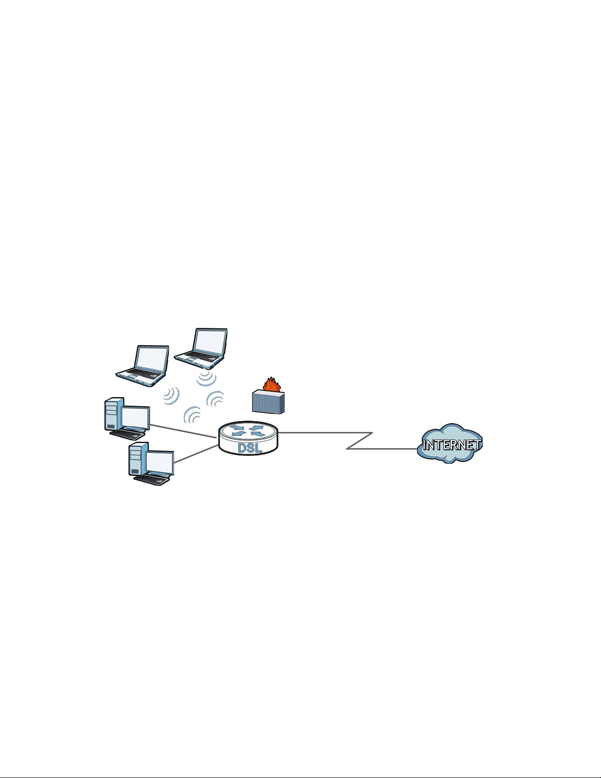
1.4.1 Internet Access
Your Device provides shared Internet access by connecting the DSL port to the DSL or MODEM jack
on a splitter or your telephone jack. Computers can connect to the Device’s LAN ports (or
wirelessly).
ow how to restore it). Restoring an earlier
Figure 1 De
Configure firewall and filtering features on the Device for secure Internet access. Set the firewall to
allow responses from the Internet for traffic initiated from your network and block traffic initiated
from the Internet. This blocks probes from the outside to your network, but lets you safely browse
the Internet and download files.
Use the filtering feature to block acce
Yahoo Messenger. You can also configure IP/MAC filtering rules for incoming or outgoing traffic.
vice’s Router Features
ss to specific web sites or Internet applications such as MSN or
Use QoS to efficiently manage traffic on your ne
and/or to particular computers. For example, you could make sure that the Device gives voice over
Internet calls high priority, and/or limit bandwidth devoted to the boss’s excessive file downloading.
twork by giving priority to certain types of traffic
Chapter 1 Introduction 10
Page 11
1.5 Wireless Access
The Device serves as a wireless Access Point (AP) to let wireless clients such as notebook computers,
smart phones, and tablets connect to the Internet without Ethernet cables.
Configure your wireless network through the
Figure 2 Wir
eless Access Example
1.5.1 Using the WLAN/WPS Button
By default, the Device’s wireless network is enabled. To turn it off, simply press the WPS/WLAN
button on top of the Device for over 5 seconds. The WLAN/WPS LED turns off.
Use the WLAN/WPS
WPS-compatible client by adding one device at a time. To activate WPS:
button to quickly set up a secure wireless connection between the Device and a
Web Configurator, or the WPS button.
1 W
ith the POWER LED on steady, press the WLAN/WPS button for 1 second and release it.
Chapter 1 Introduction 11
Page 12
ithin two minutes, press the WPS button on a WPS-enabled client within range of the Device. The
2 W
WPS/WLAN LED should flash while the Device sets up a WPS connection with the client.
e WPS/WLAN LED shines green for a successful connection.
3 Th
1.6 The RESET Button
If you forget your password or cannot access the web configurator, use the RESET button at the
back of the device to reload the factory-default configuration file. This means that you will lose all
configurations that you had previously and the user name and password will be reset to the default.
1.6.1 Using the Reset Button
With the POWER LED on steady, press the RESET button for ten seconds or until the POWER LED
begins to blink and then release it. When the POWER LED begins to blink, the defaults have been
restored and the device restarts.
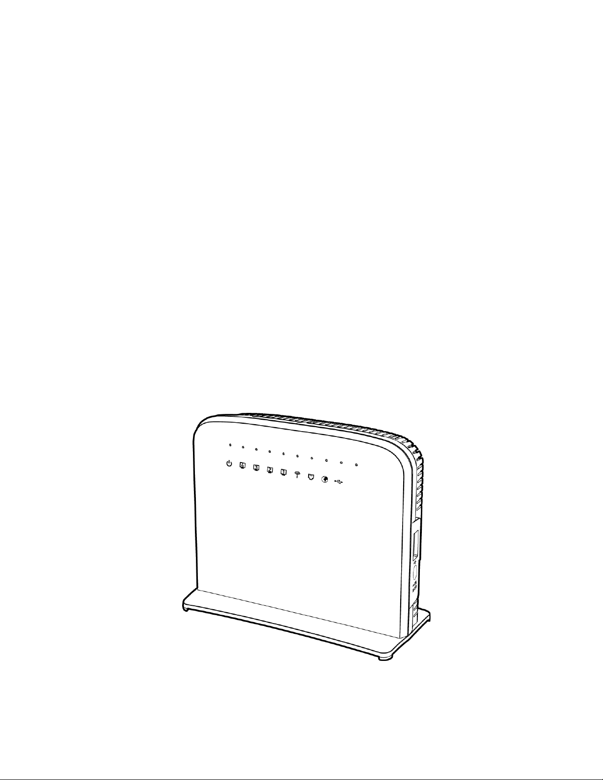
1.7 LEDs (Lights)
The following graphic displays the labels of the LEDs.
Figure 3 LE
Ds
Chapter 1 Introduction 12
Page 13

None of the LEDs are on if the Device is not receiving power.
Table 1 LE
LED COLOR STATUS DESCRIPTION
POWER Green On The Device is receiving power and ready for use.
ETHERNET
1-4
WLAN/
WPS
D Descriptions
Blinking The Device is self-testing.
Red On The Device has hardware failure.
Blinking Firmware upgrade is in progress.
Off The Device is not receiving power.
Green On The Device has a successful 100 Mbps Ethernet connection with a
de
vice on the Local Area Network (LAN).
Blinking The Device is sending or receiving data to/from the LAN at 100 Mbps.
Off The Device does not have an Ethernet connection with the LAN.
Green On The wireless network is activated.
Blinking The Device is communicating with other wireless clients.
Orange Blinking The Device is setting up a WPS connection.
Off The wireless network is not activated.
DSL Green On The DSL line is up.
Blinking The DSL line is initializing.
Off The DSL line is down.
INTERNET Green On The Device has an IP connection but no traffic.
Your device has a WAN IP address (either static or assigned by a DHCP
server), PPP nego
DSL connection is up.
Blinking The Device is sending or receiving IP traffic.
Off The Device does not have an IP connection.
Red On The Device attempted to make an IP connection but failed.
USB Green On The Device recognizes a USB connection through the USB slot.
Blinking The Device is sending or receiving data to or from the connected USB
de
vice.
Off The Device does not detect a USB connection through the USB slot.
tiation was successfully completed (if used) and the
Refer to the Quick Start Guide for information on hardware connections.
Chapter 1 Introduction 13
Page 14

Chapter 1 Introduction 14
Page 15

CHAPTER 2
Chapter 2
Introducing the Web Configurator
2.1 Overview
The web configurator is an HTML-based management interface that allows easy device setup and
management via Internet browser. Use Internet Explorer 6.0 and later versions, Mozilla Firefox 3
and later versions, or Safari 2.0 and later versions. The recommended screen resolution is 1024 by
768 pixels.
In order to use the web configurator you need to allow:
• Web browser pop-up windows from your device. W
Windows XP SP (Service Pack) 2.
• JavaScript (enabled by default).
• Java permissions (enabled b
y default).
2
eb pop-up blocking is enabled by default in
Chapter
2.1.1 Accessing the Web Configurator
1 Make sure your Device hardware is properly connected (refer to the Quick Start Guide).
2 Launch
3 T
4 A
password to access the device’s Web Configurator. Click Login. If you have changed the password,
enter your password and click Login.
Figure 4 P
your web browser.
ype "192.168.1.1" as the URL.
password screen displays. Type “admin” as the default Username and “1234” as the default
assword Screen
Chapter 2 Introducing the Web Configurator 15
Page 16
For security reasons, the Device automatically logs you out if you do not use the web
configurator for five minutes (default). If this happens, log in again.
5 The following screen displays if you have not yet changed your password. It is strongly
recommended you change the default password. Enter a new password, retype it to confirm and
click Apply; alternatively click Skip to proceed to the main menu if you do not want to change the
password now.
Figure 5 Cha
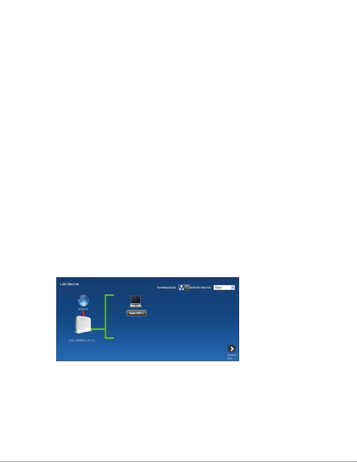
6 The Connection Status screen appears.
Figure 6 Connection Status
nge Password Screen
Chapter 2 Introducing the Web Configurator 16
Page 17
lick System Info to display the System Info screen, where you can view the Device’s interface and
B
C
A
a
b
7 C
system information.
2.2 The Web Configurator Layout
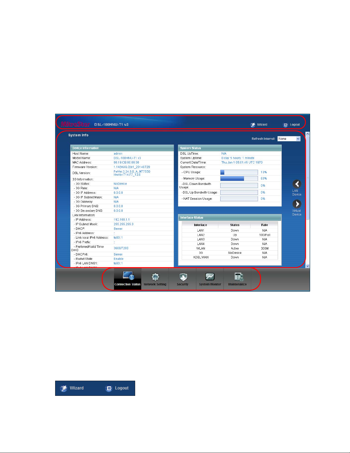
Click Connection Status > System Info to show the following screen.
Figure 7 W
eb Configurator Layout
As illustrated above, the main screen is divided into these parts:
• A - ti
• B -
• C - navig
2.2.1 Title Bar
The title bar shows the Wizard and Logout icons in the upper right corner.
Chapter 2 Introducing the Web Configurator 17
tle bar
main window
ation panel
Page 18
Click the Wizar
configurator.
d icon to configure basic initial settings. Click the Logout icon to log out of the web
2.2.2 Main Window
The main window displays information and configuration fields. It is discussed in the rest of this
document.
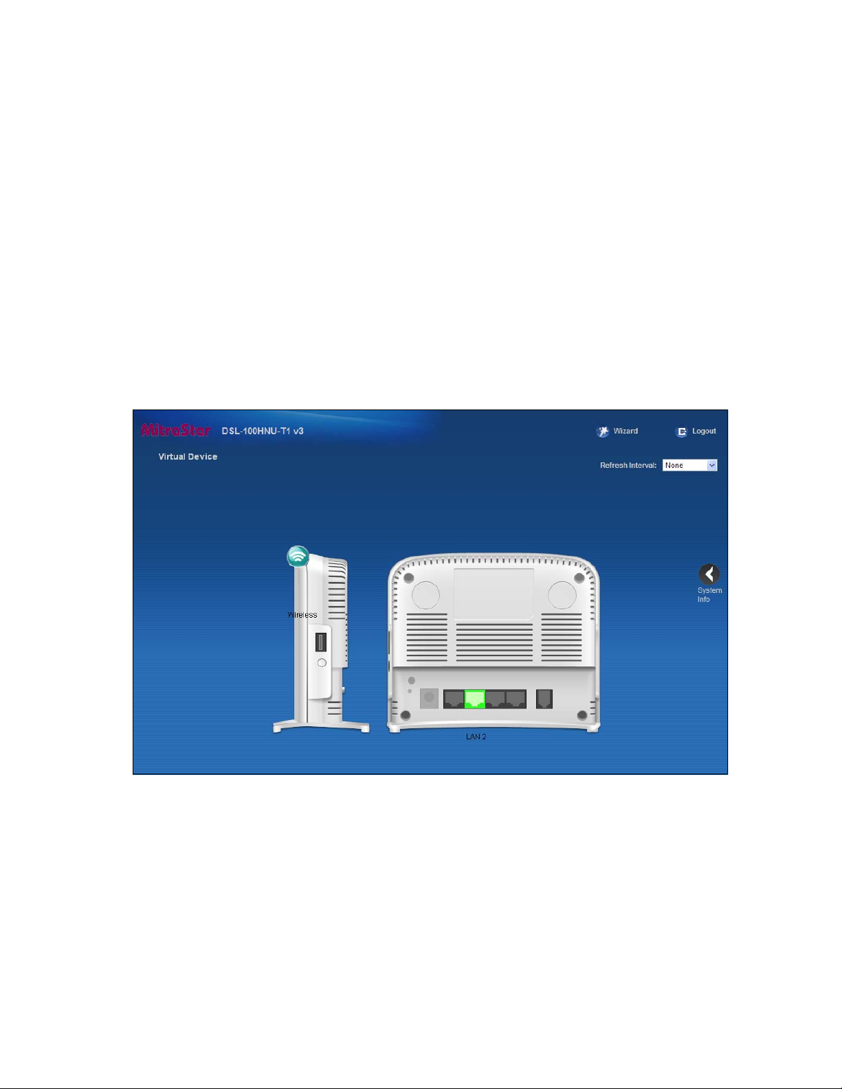
Click LAN De
Status sc
Status sc
Click Virtual De
showing the connection status of the Device’s ports
disconnected ports are gray.
Figure 8
vice on the System Info screen (a in Figure 7 on page 17) to display the Connection
reen. See Chapter 4 on page 24 for more information on the System Info and Connection
reens.
vice on the System Info screen (b in Figure 7 on page 17) to display a visual graphic
Virtual Device
. The connected ports are in color and
Chapter 2 Introducing the Web Configurator 18
Page 19
CHAPTER 3
Chapter 3
Quick Start
3
3.1 Overview
Use the Quick Start screens to configure the Device’s time zone, basic Internet access, and wireless
settings.
See the rest of this guide for background information on the features in this chapter.
3.2 Quick Start Setup
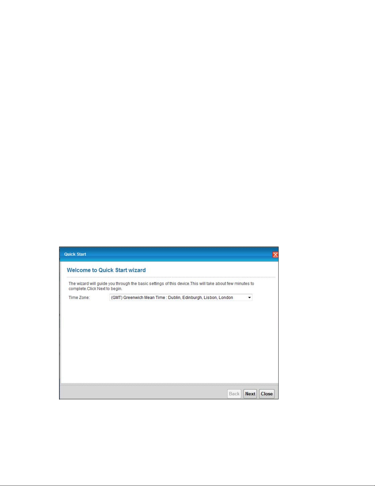
1 The Quick Start Wizard appears automatically after login. Or you can click the Start icon in the top
right corner of the web configurator to open the quick start screens. Select the time zone of the
Device’s location and click Next.
Chapter
Figure 9 Time Zone
Chapter 3 Quick Start 19
Page 20

2 Enter you
depending on your current connection type. Click Next.
r Internet connection information in this screen. The screen and fields to enter may vary
Figure 10 W
AN Interface Selection
Chapter 3 Quick Start 20
Page 21
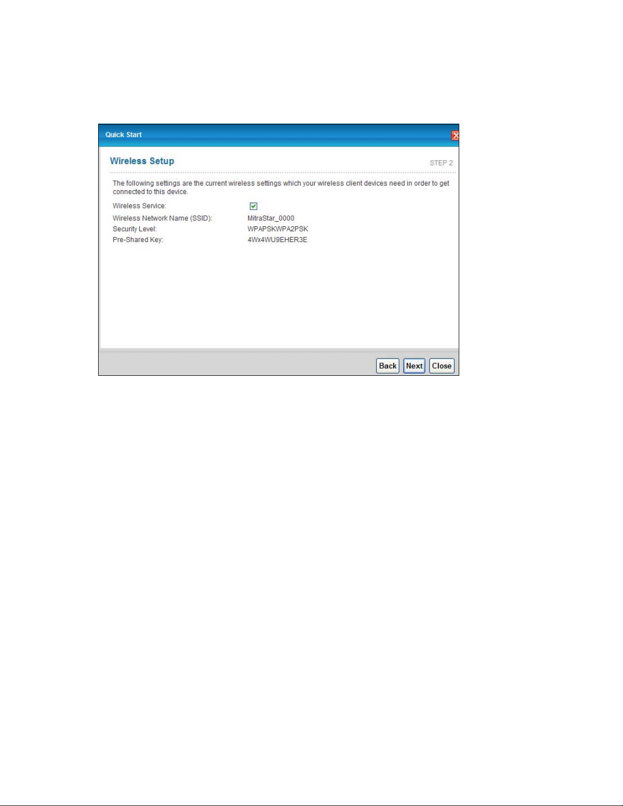
urn the wireless LAN on or off. If you keep it on, record the security settings so you can configure
3 T
your wireless clients to connect to the Device. Click Save.
Figure 11 Intern
et Connection
4 Your Device saves your settings and attempts to connect to the Internet.
Chapter 3 Quick Start 21
Page 22
CHAPTER 4
Chapter 4
Connection Status and System
Info
4.1 Overview
After you log into the web configurator, the Connection Status screen appears. This shows the
network connection status of the Device and clients connected to it.
Use the Sys
(LAN, WAN and WLAN), and SIP accounts. You can also register and unregister SIP accounts.
If you click Virtual De
connection status of the Device’s ports. See Section 2.2.2 on page 18 for more information.
tem Info screen to look at the current status of the device, system resources, interfaces
4
vice on the System Info screen, a visual graphic appears, showing the
Chapter
4.2 The Connection Status Screen
Use this screen to view the network connection status of the device and its clients. A warning
message appears if there is a connection problem. You can configure how often you want the
Device to update this screen in Refresh Interval.
Figure 12 Conn
ection Status: Icon View
Chapter 4 Connection Status and System Info 22
Page 23

To view the connected LAN devices in a list, click Li
st View in the Viewing mode selection box.
Figure 13 Conn
In Icon View, if you want to view information about a client, click the client’s name and Info.
In Li
st View, you can also view the client’s information.
ection Status: List View
Chapter 4 Connection Status and System Info 23
Page 24
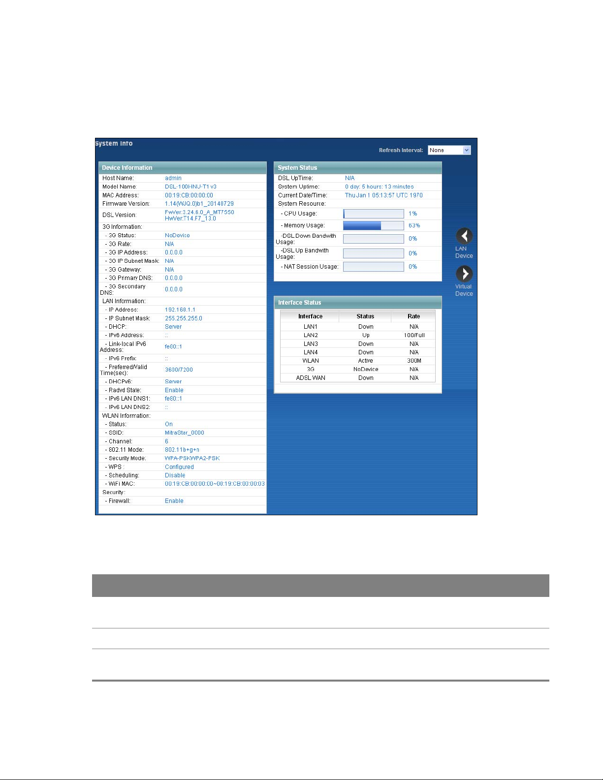
4.3 The System Info Screen
Click Connection Status > System Info to open this screen.
Figure 14
System Info Screen
Each field is described in the following table.
Table 2 S
LABEL DESCRIPTION
Refresh Interval Select how often you want the Device to update this screen from the drop-down list
Device Information
Host Name This field displays the Device system name. It is
ystem Info Screen
bo
x.
this in the Maintenance > System screen’s Host Name field.
used for identification. You can change
Chapter 4 Connection Status and System Info 24
Page 25

Table 2 System Info Screen (continued)
LABEL DESCRIPTION
Model Name This is the model name of your device.
MAC Address This is the MAC (Media Access Control) or Ethernet address unique to your Device.
Firmware Version This field displays the current version of the firmware inside the device. It also shows
the date the firmware version was created. Go to the Maintenance > Firmware
Upgrade screen to change it.
DSL Version This is the current version of the Device’s DSL modem code.
3G Information
3G Status This shows the current status of your 3G connection. NoDevice is shown when no 3G
card is inserted.
3G Rate This shows the rate of the 3G connection if it is available.
3G IP Address This shows the IP address for the 3G connection.
3G IP Subnet
Mask
3G Gateway This shows the IP address of the 3G connection’s default gateway.
3G Primary/
Secondary DNS
LAN Information
IP Address This field displays the current IP address of the Device in the LAN.
IP Subnet Mask This field displays the current subnet mask in the LAN.
DHCP This field displays what DHCP services the Device is providing to the LAN. Choices are:
IPv6 Address This is the current IPv6 address of the Device in the LAN.
Link-local IPv6
Address
IPv6 Prefix This is the current IPv6 prefix length in the LAN.
Preferred/Valid
Time(sec)
This shows the current subnet mask for the 3G connection.
This shows the first and second DNS server address assigned by the ISP.
Server - The Device is a DHCP server in the LAN. It assigns IP addresses to other
computers in the LAN.
None - The Device is not providing any DHCP services to the LAN.
This is the current LAN IPv6 link-local address of the Device.
This is the Preferred Lifetime and Valid Lifetime in the LAN.
DHCPv6 This field displays what DHCPv6 services the Device is providing to the LAN. Choices
are:
Server - The Device is a DHCPv6 server in the LAN. It assigns IP addresses to other
computers in the LAN.
None - The Device is not providing any DHCPv6 services to the LAN.
Chapter 4 Connection Status and System Info 25
Page 26

Table 2 System Info Screen (continued)
LABEL DESCRIPTION
Radvd State This shows the status of RADVD.
IPv6 LAN DNS1/
DNS2
WLAN Information
Status This shows whether or not the wireless LAN is enabled (on).
SSID This is the descriptive name used to identify the Device in the wireless LAN.
Channel This is the channel number used by the Device now.
802.11 Mode This displays the type of 802.11 mode the Device is using in the wireless LAN.
Security Mode This displays the type of security the Device is using in the wireless LAN.
WPS Configured displays when a wireless client has connected to the Device or WPS is
Scheduling This shows whether wireless scheduling is enabled or disabled.
WiFi MAC This is the MAC (Media Access Control) or Ethernet address unique to your Device’s
Security
Firewall This shows whether or not the firewall is enabled (on).
This is the first/second DNS server IPv6 address the Device passes to the DHCP clients.
enabled and wireless or wireless security settings have been configured.
Unconfigured displays if WPS wireless security settings have not been configured. Off
displays if WPS is disabled.
WiFi interface.
System Status
DSL UpTime This field displays how long the DSL connection has been active.
System Uptime This field displays how long the Device has been running since it last started up. The
Device starts up when you plug it in, when you restart it (Maintenance > Reboot), or
when you reset it (see
Current Date/
Time
CPU Usage This field displays what percentage of the Device’s processing ability is currently used.
Memory Usage This field displays what percentage of the Device’s memory is currently used. Usually,
This field displays the current date and time in the Device. You can change this in
Maintenance > Time Setting.
When this percentage is close to 100%, the Device is running at full load, and the
throughput is not going to improve anymore. If you want some applications to have
more throughput, you should turn off other applications.
this percentage should not increase much. If memory usage does get close to 100%,
the Device is probably becoming unstable, and you should restart the device. See
Chapter 24 on page 202, or turn off the device (unplug the power) for a few seconds.
Section 1.6 on page 12).
Chapter 4 Connection Status and System Info 26
Page 27

Table 2 System Info Screen (continued)
LABEL DESCRIPTION
DSL Down
Bandwith
Usage
DSL Up
Bandwith
Usage
NAT Session
Usage
Interface Status
Interface This column displays each interface the Device has.
Status This field indicates whether or not the Device is using the interface.
This field displays what percentage of the Device’s downstream DSL bandwidth is
currently used. When this percentage is close to 100%, the Device is running at full
load, and the throughput is not going to improve anymore. If you want some
applications to have more throughput, you should turn off other applications.
This field displays what percentage of the Device’s upstream DSL bandwidth is
currently used. When this percentage is close to 100%, the Device is running at full
load, and the throughput is not going to improve anymore. If you want some
applications to have more throughput, you should turn off other applications.
This field displays what percentage of the Device supported NAT sessions are currently
being used.
For the LAN interfaces, this field displays Up when the Device is using the interface and
Down when the Device is not using the interface.
For the WLAN interface, it displays Active when WLAN is enabled or Down when
WLAN is disabled.
For the 3G USB interface, this field displays Up when using the interface and NoDevice
when no device is detected in any USB slot.
For the xDSL WAN interface, this field displays Down when the line is down or Up
when line is up or connected.
Rate For the LAN interface, this displays the port speed and duplex setting.
For the WLAN interface, it displays the maximum transmission rate when WLAN is
enabled or N/A when WLAN is disabled.
For the 3G interface, it displays the maximum transmission rate when 3G is enabled or
N/A when 3G is disabled.
For the xDSL WAN interface, it displays the downstream and upstream transmission
rate.
Chapter 4 Connection Status and System Info 27
Page 28
CHAPTER 5
WAN
LAN
Chapter 5
WAN Setup
5.1 Overview
This chapter describes how to configure WAN settings from the WAN screens. Use these screens to
configure your Device for Internet access.
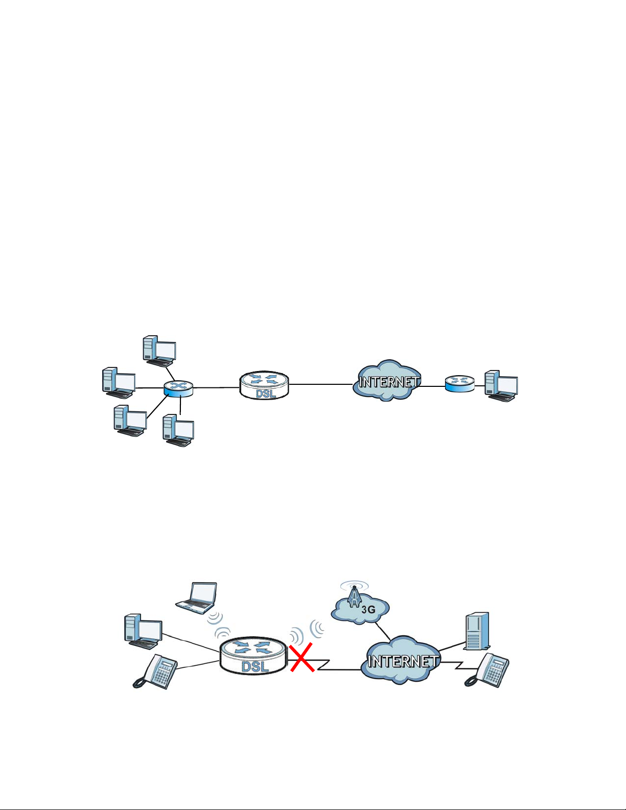
A WAN (Wide Area Network) connection connects to another network or the Internet. It connects
your
private networks (such as a LAN (Local Area Network) and other networks, so that a computer
in one location can communicate with computers in other locations.
Figure 15 LA
N and WAN
5
Chapter
3G (third generation) standards for the sending and receiving of voice, video, and data in a mobile
environment.
You can attach a 3G wireless adapter to the USB port
as your WAN or a backup when the wired WAN connection fails.
Figure 16 3
G WAN Connection
and set the Device to use this 3G connection
Chapter 5 WAN Setup 28
Page 29

5.1.1 What You Can Do in the WAN Screens
•Use the Internet Connection screen (Section 5.2 on page 32) to configure the WAN settings on
the Device for Internet access.
•Use the More Connections screen (Section 5.3 on page 38) to set up additional Internet access
connections.
•Use the 3G Backup screen to configure 3G WAN connection (Section 5.4 on page 44).
5.1.2 What You Need to Know About WAN
Encapsulation Method
Encapsulation includes data from an upper layer protocol into a lower layer protocol. To set up a
WAN connection to the Internet, you need to use the same encapsulation method used by your ISP
(Internet Service Provider). If your ISP offers a dial-up Internet connection using PPPoE (PPP over
Ethernet) or PPPoA, they should also provide a username and password (and service name) for user
authentication.
WAN IP Address
The Device uses its WAN IP address to connect to the Internet and communicate with devices in
other networks. It can be static (fixed) or dynamically assigned by the ISP when the Device connects
to the Internet.
If your ISP assigns you a static WAN IP address, they should also assign you the subnet mask and
DNS server IP address(es) (and a gateway IP address if you use the Ethernet or ENET ENCAP
encapsulation method).
Multicast
Traditionally, IP packets are transmitted in one of either two ways - Unicast (1 sender - 1 recipient) or
Broadcast (1 sender - everybody on the network). Multicast delivers IP packets to a group of hosts
on the network - not everybody and not just one.
IGMP
Devices use the IGMP (Internet Group Management Protocol) network-layer protocol to establish
membership in a multicast group - it does not carry user data. IGMP versions 2 and 3 offer
improvements over the widely-used version 1.
IPv6
IPv6 (Internet Protocol version 6) provides increased IP address space and enhanced features in
comparison to IPv4. The Device supports IPv4/IPv6 dual stack and can connect to IPv4 and IPv6
networks.
Chapter 5 WAN Setup 29
Page 30
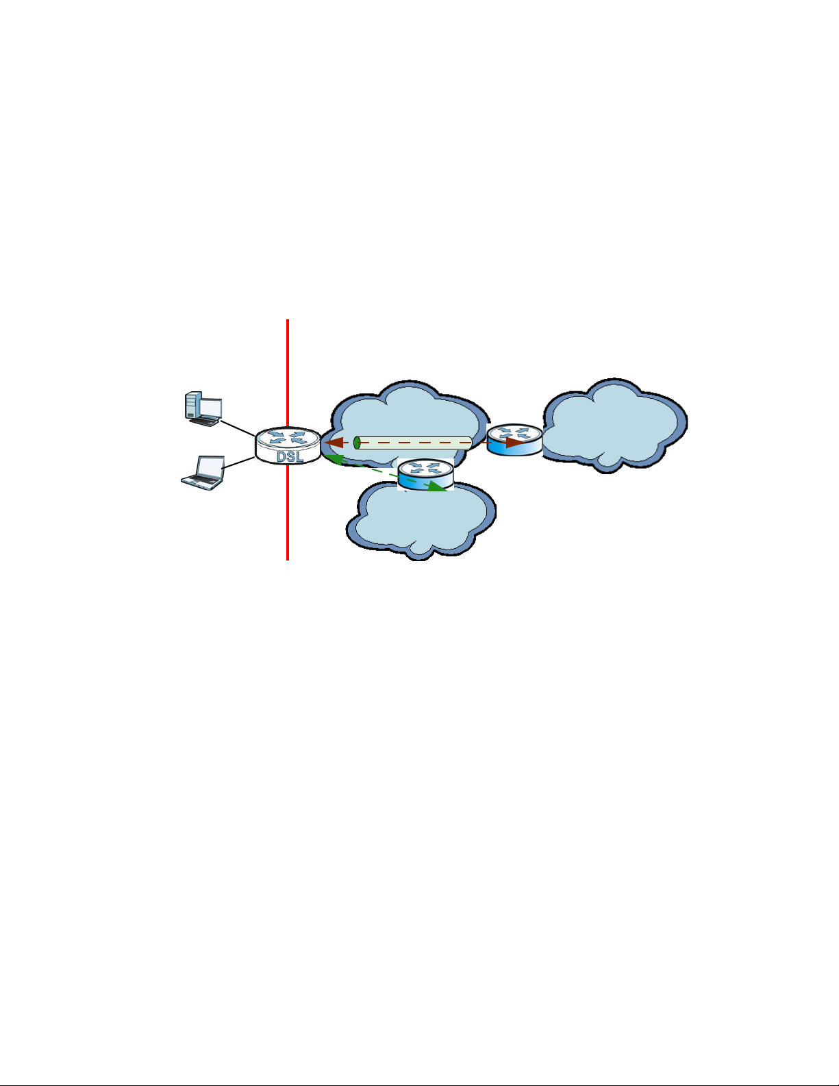
IPv6 Rapid Deployment
ISP (IPv4)
IPv6 Internet
IPv4
IPv6
BR
IPv6 in IPv4
IPv4 Internet
IPv4
+
LAN
- IPv6
- IPv4
WAN
- IPv4
- IPv6 in IPv4
Use IPv6 Rapid Deployment (6rd) when the local network uses IPv6 and the ISP has an IPv4 network.
hen the Device has an IPv4 WAN address and you set IPv6/IPv4 Dual Stack to IPv4, you can
W
enable 6rd to encapsulate IPv6 packets in IPv4 packets to cross the ISP’s IPv4 network.
The Device generates a global IPv6 prefix from its
ISP’s Border Relay router (BR in the figure) to connect to the native IPv6 Internet. The local network
can also use IPv4 services. The Device uses it’s configured IPv4 WAN IP to route IPv4 traffic to the
IPv4 Internet.
Figure 17
IPv6 Rapid Deployment
IPv4 WAN address and tunnels IPv6 traffic to the
Dual Stack Lite
Use Dual Stack Lite when local network computers use
the Device has an IPv6 WAN address and you set IPv6/IPv4 Dual Stack to IPv6, you can enable Dual
Stack Lite to use IPv4 computers and services.
IPv4 and the ISP has an IPv6 network. When
Chapter 5 WAN Setup 30
Page 31

The Device tunnels IPv4 packets inside IPv6 encapsulation packets to the ISP’s Address Family
ISP (IPv6)
IPv6 Internet
IPv6
AFTR
IPv4 in IPv6
IPv4 Internet
IPv6
IPv4
+
LAN
- IPv6
- IPv4
WAN
- IPv6
- IPv4 in IPv6
ransition Router (AFTR in the graphic) to connect to the IPv4 Internet. The local network can also
T
use IPv6 services. The Device uses it’s configured IPv6 WAN IP to route IPv6 traffic to the IPv6
Internet.
Figure 18
3G
3G (Third Generation) is a digital, packet-switc
optimized as multiple users share the same channel and bandwidth is only allocated to users when
they send data. It allows fast transfer of voice and non-voice data and provides broadband Internet
access to mobile devices.
Dual Stack Lite
hed wireless technology. Bandwidth usage is
Finding Out More
See Section 5.5 on page 47 for technical background information on WAN.
5.1.3 Before You Begin
You need to know your Internet access settings such as encapsulation and WAN IP address. Get this
information from your ISP.
Chapter 5 WAN Setup 31
Page 32

5.2 The Internet Connection Screen
Use this screen to change your Device’s WAN settings. Click Network Setting > Broadband >
Internet Connection. The screen differs by the mode and encapsulation you select.
Figure 19 Network Setting
> Broadband > Internet Connection
Chapter 5 WAN Setup 32
Page 33

The following table describes the labels in this screen.
Table 3 Network Setting > Broadband >Internet Connection
LABEL DESCRIPTION
Line
ADSL Mode Select the kind of connection your Device uses to connect to the ISP.
Use Auto Sync-Up if you are not sure which type to choose.
Use ADSLT1.413, ADSLG.DMT, ADSLG.lite, ADSL2, ADSL2+, ADSL2_AnnexM,
ADSL2+_AnnexM, or READSL2 if you know the specific type of DSL the Device uses
to connect to the ISP.
General
Mode Select Router (default) from the drop-down list box if your ISP gives you one IP
address only and you want multiple computers to share an Internet account. Select
Bridge when your ISP provides you more than one IP address and you want the
connected computers to get individual IP address from ISP’s DHCP server directly. If
you select Bridge, you cannot use Firewall, DHCP server and NAT on the Device.
Encapsulation Select the method of encapsulation used by your ISP from the drop-down list box.
This field is available if you select Router in the Mode filed.
User Name (PPPoA and PPPoE encapsulation only) Enter the user name exactly as your ISP
assigned. If assigned a name in the form user@domain where domain identifies a
service name, then enter both components exactly as given.
Password (PPPoA and PPPoE encapsulation only) Enter the password associated with the user
name above.
Service Name (PPPoE only) Type the name of your PPPoE service here.
Multiplex This displays for an ADSL virtual channel. Select the method of multiplexing used by
your ISP from the drop-down list. Choices are VC-Mux or LLC.
IPv6/IPv4 Dual Stack This is not available if you select PPPoA in the Encapsulation field.
Select IPv4 to have the Device use only IPv4.
Select IPv4/IPv6 to let the Device connect to IPv4 and IPv6 networks and choose the
protocol for applications according to the address type.
Select IPv6 to have the Device use only IPv6.
PPP Authentication This is available if you select PPPoE or PPPoA in the Encapsulation field.
The Device supports PAP (Password Authentication Protocol) and CHAP (Challenge
Handshake Authentication Protocol). CHAP provides more security than PAP;
however, PAP has higher availability on more platforms.
Use the drop-down list box to select an authentication protocol for outgoing calls.
Options are:
Auto- Your Device accepts either CHAP or PAP when requested by this remote node.
CHAP - Your Device accepts CHAP only.
PAP - Your Device accepts PAP only.
Chapter 5 WAN Setup 33
Page 34

Table 3 Network Setting > Broadband >Internet Connection (continued)
LABEL DESCRIPTION
Virtual Circuit ID VPI (Virtual Path Identifier) and VCI (Virtual Channel Identifier) define a virtual circuit.
Refer to the appendix for more information.
IP Address You can use these options when you set the Mode field to Router and the IPv6/IPv4
Dual Stack field to IPv4 or IPv4/IPv6.
Select Obtain an IP Address Automatically if the ISP assigns you a dynamic IP
address; otherwise select Static IP Address and type your ISP assigned IP address in
the IP Address field below.
Static IP Address Select this option If the ISP assigned a fixed IP address.
IP Address Enter the static IP address provided by your ISP.
IPv6 Tunnel Mode This is available if you select ENET ENCAP or PPPoE in the Encapsulation field and
IPv4 in the IPv6/IPv4 Dual Stack field.
Select 6rd to tunnel IPv6 traffic from the local network through the ISP’s IPv4
network.
Select 6to4 to enable IPv6 to IPv4 tunneling. This will encapsulate IPv6 packets in
IPv4 packets so they can travel through IPv4 networks.
Relay Server If you select 6to4 in the IPv6 Tunnel Mode field, enter the tunneling relay server's
IPv4 address in this field.
Via DHCP Option
212
Manual Select this to manually enter the following 6rd information.
6rd Prefix Enter an IPv6 prefix for tunneling IPv6 traffic to the ISP’s Border Relay router and
6rd Prefix Length Enter the IPv6 prefix length.
IPv4 Mask Length Enter the subnet mask number for the IPv4 network.
Relay Server Enter the relay server’s IPv4 address.
DNS Server
Primary / Secondary
DNS
IPv6 Address
Obtain an IP Address
Automatically
Select this to have the Device detect it automatically through DHCP option 212.
connecting to the native IPv6 Internet.
Set how the Device gets the IP addresses of the DNS servers it uses.
UserDefined - enter a static IP address.
Obtained From ISP - when the Device gets its IP address automatically, you can
select this to have it also get the DNS server address.
None - the Device does not use the DNS server entry.
Select this option to have the Device use the IPv6 prefix from the connected router’s
Router Advertisement (RA) to generate an IPv6 address.
Static IP Address When you set the Encapsulation field to ENET ENCAP, select the Static IP Address
option if you have a fixed IPv6 address assigned by your ISP.
Chapter 5 WAN Setup 34
Page 35

Table 3 Network Setting > Broadband >Internet Connection (continued)
LABEL DESCRIPTION
DHCP IPv6 Select DHCP&SLAAC to have the use both DHCPv6 and SLAAC to get an IP address.
Select DHCP to obtain an IPv6 address from a DHCPv6 server. The IP address
assigned by a DHCPv6 server has priority over the IP address automatically
generated by the Device using the IPv6 prefix from an RA.
Select Auto to have the Device try to use DHCPv6 to get an IP address and then
SLAAC if DHCPv6 does not work.
Select SLAAC (Stateless address autoconfiguration) to have the Device use the prefix
to automatically generate a unique IP address that does not need to be maintained
by a DHCP server.
Select None if you do not want the Device to obtain an IPv6 address from a DHCPv6
server.
DHCP PD Select Enable to use DHCP PD (Prefix Delegation) to allow the Device to pass the IPv6
prefix information to its LAN hosts. The hosts can then use the prefix to generate
their IPv6 addresses.
Dual Stack Lite The Dual Stack Lite fields display when you set the IPv6/IPv4 Dual Stack field to
IPv6. Enable Dual Stack Lite to let local computers use IPv4 through an ISP’s IPv6
network.
Mode Select Manual if you have the IPv6 address of the Address Family Transition Router
(AFTR), otherwise select Auto to have the Device detect it automatically through
DHCPv6.
Remote IPv6
Address
IPv6 Address When you enable Static IP Address, enter the IPv6 address of the Device in the
Prefix Length When you enable Static IP Address, enter the IPv6 prefix length in the WAN here.
IPv6 Default
Gat ewa y
IPv6 DNS Server1 When you enable Static IP Address, enter the primary DNS server IPv6 address
IPv6 DNS Server2 When you enable Static IP Address, enter the secondary DNS server IPv6 address
WAN Identifier Type Select Manual to manually enter a WAN Identifier as the interface ID to identify the
WAN Identifier If you selected Manual, enter the WAN Identifier in this field. The WAN identifier
When you set the Mode field to Manual, specify the AFTR IPv6 address.
WAN.
When you enable Static IP Address, enter the IPv6 address of the default gateway
here.
here.
here.
WAN interface. The Device appends the WAN Identifier to the IPv6 address prefix to
create the routable global IPv6 address. Select EUI64 to use the EUI-64 format to
generate an interface ID from the MAC address of the WAN interface.
should be unique and 64 bits in hexadecimal form. Every 16 bit block should be
separated by a colon as in XXXX:XXXX:XXXX:XXXX where X represents a hexadecimal
character. Blocks of zeros can be represented with double colons as in
XXXX:XXXX::XXXX.
Connection (PPPoA and PPPoE encapsulation only)
Chapter 5 WAN Setup 35
Page 36

Table 3 Network Setting > Broadband >Internet Connection (continued)
LABEL DESCRIPTION
Keep Alive Select Keep Alive when you want your connection up all the time. The Device will try
to bring up the connection automatically if it disconnects.
Connect on Demand Select C
specify an idle time-out in the Max Idle Timeout field.
Max Idle Time Specify an idle time-out in the Max Idle Timeout field when you select Connect on
Demand. The default setting of 0 means the Internet session will not timeout.
Apply Click this to save your changes.
Cancel Click this to restore your pr
Advanced Setup Click this to display the Advanced
details of your WAN setup.
onnect on Demand when you don't want the connection up all the time and
5.2.1 Advanced Internet Connection
Use this screen to edit your Device's advanced WAN settings. Click the Advanced Setup button in
the Internet Connection screen. The screen appears as shown.
Figure 20 Intern
et Connection: Advanced Setup
eviously saved settings.
Internet Connection section and edit more
Chapter 5 WAN Setup 36
Page 37

The following table describes the labels in this screen.
Table 4 Internet Connection: Advanced Setup
LABEL DESCRIPTION
RIP & Multicast
Setup
RIP Direction RIP (Routing Information Protocol) allows a router to exchange routing information
RIP Version This field does not apply if you select None in the RIP Direction field.
Multicast Multicast packets are sent to a group of computers on the LAN and are an alternative
MLD Proxy Select the version of MLD proxy (v1 or v2) to have the Device act as for this
ATM QoS This section is available when the connection’s Virtual Channel field is set to an ADSL
This section does not apply when you configure the Device to bridge mode.
with other routers. Use this field to control how much routing information the Device
sends and receives on the subnet.
Select the RIP direction from None, Both, In Only and Out Only.
Select the RIP version from RIP-1, RIP-2B/RIP-2M.
to unicast packets (packets sent to one computer) and broadcast packets (packets
sent to every computer).
Devices use the IGMP (Internet Group Management Protocol) network-layer protocol
to establish membership in a multicast group. Select IGMP v1/IGMP v2/IGMP v3.
Select None to disable it.
connection. This allows the Device to get subscription information and maintain a
joined member list for each multicast group. It can reduce multicast traffic
significantly. Select None to turn off MLD proxy.
option.
ATM QoS Type Select CBR (Continuous Bit Rate) to specify fixed (always-on) bandwidth for voice or
data traffic. Select UBR With PCR (Unspecified Bit Rate with Peak Cell Rate) for
applications that are non-time sensitive, such as e-mail. Select Non Realtime VBR
(Variable Bit Rate-non Real Time) or Realtime VBR (Variable Bit Rate-Real Time) for
bursty traffic and bandwidth sharing with other applications.
Peak Cell Rate Divide the DSL line rate (bps) by 424 (the size of an ATM cell) to find the Peak Cell Rate
(PCR). This is the maximum rate at which the sender can send cells. Type the PCR
here.
Sustain Cell Rate The Sustain Cell Rate (SCR) sets the average cell rate (long-term) that can be
transmitted. Type the SCR, which must be less than the PCR. Note that system default
is 0 cells/sec.
Maximum Burst
Size
PPPoE Passthrough If the encapsulation type is PPPoE, select this to enable PPPoE Passthrough. In
MTU
Maximum Burst Size (MBS) refers to the maximum number of cells that can be sent at
the peak rate. Type the MBS, which is less than 65535.
addition to the Device’s built-in PPPoE client, you can select this to allow hosts on the
LAN to use PPPoE client software on their computers to connect to the ISP via the
device. Each host can have a separate account and a public WAN IP address.
Chapter 5 WAN Setup 37
Page 38

Table 4 Internet Connection: Advanced Setup (continued)
LABEL DESCRIPTION
MTU The Maximum Transmission Unit (MTU) defines the size of the largest packet allowed
on an interface or connection. Enter the MTU in this field.
For ENET ENCAP, the MTU value is 1500.
For PPPoE, the MTU value is 1492.
For PPPoA and RFC 1483, the MTU is 65535.
Apply Click this to save your changes.
Cancel Click this to restore your
Advanced Setup Click this to close the A
5.3 The More Connections Screen
The Device allows you to configure more than one Internet access connection. To configure
additional Internet access connections click Network Setting > Broadband > More Connections.
The screen differs by the encapsulation you select. When you use the Broadband > Internet
Connection screen to set up Internet access, you are configuring the first WAN connection.
Figure 21 N
etwork Setting > Broadband > More Connections
previously saved settings.
dvanced Internet Connection section.
The following table describes the labels in this screen.
Table 5 Network Setting > Broadband > More Connections
LABEL DESCRIPTION
# This is an index number indicating the numb
Active This field indicates whether the connection is active or not. This field is read-only.
Node Name This is the name of the Internet connection.
VPI/VCI This field displays the Virtual Path Identifier (VPI) and Virtual Channel Identifier (VCI)
numbers configur
ed for this WAN connection.
er of the corresponding connection.
Chapter 5 WAN Setup 38
Page 39

Table 5 Network Setting > Broadband > More Connections (continued)
LABEL DESCRIPTION
Encapsulation This field indicates the encapsulation method and multiplexing type the Internet
connection uses.
Modify The first (ISP) connection is read-only in this screen. Use the Br
Connection screen to edit it.
Click the Ed
configuration to add a new Internet access setup.
Click the Re
5.3.1 More Connections Edit
Use this screen to configure a connection. Click the Edit icon in the More Connections screen to
display the following screen.
Figure 22 M
ore Connections: Edit
oadband > Internet
it icon to edit the Internet connection settings. Click this icon on an empty
move icon to delete the Internet access setup from your connection list.
Chapter 5 WAN Setup 39
Page 40

The following table describes the labels in this screen.
Table 6 More Connections: Edit
LABEL DESCRIPTION
General
Active Select the check box to activate or clear the check box to deactivate this connection.
Node Name Enter a unique, descriptive name of up to 13 ASCII characters for this connection.
Mode Select Router from the drop-down list box if your ISP allows multiple computers to share
an Internet account.
If you select Bridge, the Device will forward any packet that it does not route to this
remote node; otherwise, the packets are discarded.
Encapsulation Select the method of encapsulation used by your ISP from the drop-down list box. This
field is available if you select Router in the Mode field.
User Name (PPPoA and PPPoE encapsulation only) Enter the user name exactly as your ISP assigned.
If assigned a name in the form user@domain where domain identifies a service name,
then enter both components exactly as given.
Password (PPPoA and PPPoE encapsulation only) Enter the password associated with the user name
above.
Service
Name
Multiplex Select the method of multiplexing used by your ISP from the drop-down list. Choices are
IPv6/IPv4 Dual
Stack
PPP
Authentication
(PPPoE only) Type the name of your PPPoE service here.
VC-Mux or LLC.
By prior agreement, a protocol is assigned a specific virtual circuit, for example, VC1 will
carry IP. If you select VC-mux, specify separate VPI and VCI numbers for each protocol.
For LLC-based multiplexing or PPP encapsulation, one VC carries multiple protocols with
protocol identifying information being contained in each packet header. In this case, only
one set of VPI and VCI numbers need be specified for all protocols.
Select IPv4 to have the Device use only IPv4.
Select IPv4/IPv6 to let the Device connect to IPv4 and IPv6 networks and choose the
protocol for applications according to the address type.
Select IPv6 to have the Device use only IPv6.
The Device supports PAP (Password Authentication Protocol) and CHAP (Challenge
Handshake Authentication Protocol). CHAP is more secure than PAP; however, PAP is
readily available on more platforms.
Use the drop-down list box to select an authentication protocol for outgoing calls. Options
are:
AUTO - Your Device accepts either CHAP or PAP when requested by this remote node.
CHAP - Your Device accepts CHAP only.
PAP - Your Device accepts PAP only.
VPI, VCI VPI (Virtual Path Identifier) and VCI (Virtual Channel Identifier) define a virtual circuit.
Refer to the appendix for more information.
Chapter 5 WAN Setup 40
Page 41

Table 6 More Connections: Edit (continued)
LABEL DESCRIPTION
IP Address You can use these options when you set the Mode field to Router and the IPv6/IPv4
Dual Stack field to IPv4 or IPv4/IPv6.
Select Obtain an IP Address Automatically if the ISP assigns you a dynamic IP address;
otherwise select Static IP Address and type your ISP assigned IP address in the IP
Address field below.
Static IP
Address
IP Address Enter the static IP address provided by your ISP.
Subnet
Mask
Gateway IP
Address
Primary /
Secondary
DNS
IPv6 Address
Obtain an IP
Address
Automatically
Static IP
Address
Select this option If the ISP assigned a fixed IP address.
Enter a subnet mask in dotted decimal notation.
Specify a gateway IP address (supplied by your ISP).
Set how the Device gets the IP addresses of the DNS servers it uses.
UserDefined - enter a static IP address.
Obtained From ISP - when the Device gets its IP address automatically, you can select
this to have it also get the DNS server address.
None - the Device does not use the DNS server entry.
Select this option if you want to have the Device use the IPv6 prefix from the connected
router’s Router Advertisement (RA) to generate an IPv6 address.
Select this option if you have a fixed IPv6 address assigned by your ISP.
DHCP IPv6 Select DHCP if you want to obtain an IPv6 address from a DHCPv6 server.
The IP address assigned by a DHCPv6 server has priority over the IP address automatically
generated by the Device using the IPv6 prefix from an RA.
Select SLAAC (Stateless address autoconfiguration) to have the Device use the prefix to
automatically generate a unique IP address that does not need to be maintained by a
DHCP server.
DHCP PD Select Enable to use DHCP PD (Prefix Delegation) to allow the Device to pass the IPv6
prefix information to its LAN hosts. The hosts can then use the prefix to generate their
IPv6 addresses.
IPv6 Address With Static IP Address enabled, enter the IPv6 address of the Device in the WAN.
Prefix Length With Static IP Address enabled, enter the IPv6 prefix length in the WAN.
IPv6 Default
Gat ewa y
IPv6 DNS
Server1
With Static IP Address enabled, enter the IPv6 address of the default gateway
With Static IP Address enabled, enter the primary DNS server IPv6 address for the
Device.
Chapter 5 WAN Setup 41
Page 42

Table 6 More Connections: Edit (continued)
LABEL DESCRIPTION
IPv6 DNS
Server2
Connection
Keep Alive Select Keep Alive when you want your connection up all the time. The Device will try to
Connect on
Demand
Max Idle
Timeout
NAT If you set the Mode field to Router, you can select SUA Only if you have one public IP
Back Click this to return to the previous screen without saving.
Apply Click this to save your changes.
Advanced
Setup
With Static IP Address enabled, enter the secondary DNS server IPv6 address for the
Device.
bring up the connection automatically if it disconnects.
Select Connect on Demand when you don't want the connection up all the time and
specify an idle time-out in the Max Idle Timeout field.
Specify an idle time-out in the Max Idle Timeout field when you select Connect on
Demand. The default setting of 0 means the Internet session will not timeout.
address and want to use NAT.
Otherwise, select None to disable NAT.
Click this to display the More Connections Advanced Setup screen and edit more details
of your WAN setup.
Chapter 5 WAN Setup 42
Page 43

5.3.2 Configuring More Connections Advanced Setup
Use this screen to edit your Device's advanced WAN settings. Click the Advanced Setup button in
the More Connections Edit screen. The screen appears as shown.
Figure 23 Mor
e Connections: Edit: Advanced Setup
The following table describes the labels in this screen.
Table 7 Mor
LABEL DESCRIPTION
RIP & Multicast Setup
RIP Direction Select the RIP Dir
RIP Version You do not configure this field if you set the RIP Dir
Multicast Devices use the IGMP (Internet Group Management Protocol) network-layer
MLD Proxy Select the version of MLD proxy (v1 or v2) to have the Device act as for this
ATM QoS
e Connections: Edit: Advanced Setup
ection from None, Both, In Only and Out Only.
Select the RIP V
pr
otocol to establish membership in a multicast group. Select IGMP v1/IGMP-v2/
IGMP-v3. Select None to disable it.
connection. This al
joined member list for each multicast group. It can reduce multicast traffic
significantly. Select None to turn off MLD proxy.
ersion from RIP-1, RIP-2B/RIP-2M.
lows the Device to get subscription information and maintain a
ection field to None.
Chapter 5 WAN Setup 43
Page 44

Table 7 More Connections: Edit: Advanced Setup (continued)
LABEL DESCRIPTION
ATM QoS Type Select CBR (Continuous Bit Rate) to specify fixed (always-on) bandwidth for voice or
data traffic. Select UBR With PCR (Unspecified Bit Rate with Peak Cell Rate) for
applications that are non-time sensitive, such as e-mail. Select Non Realtime VBR
(Variable Bit Rate-non Real Time) or Realtime VBR (Variable Bit Rate-Real Time) for
bursty traffic and bandwidth sharing with other applications.
Peak Cell Rate Divide the DSL line rate (bps) by 424 (the size of an ATM cell) to find the Peak Cell
Rate (PCR). This sets the maximum rate at which the sender can send cells. Type
the PCR here.
Sustain Cell Rate The Sustain Cell Rate (SCR) sets the average cell rate (long-term) that can be
transmitted. Type the SCR, which must be less than the PCR. Note the system
default of 0 cells/sec.
Maximum Burst
Size
PPPoE Passthrough When using the PPPoE the encapsulation type, select this to enable PPPoE
MTU
MTU The Maximum Transmission Unit (MTU) defines the size of the largest packet
Apply Click this to save your changes.
Cancel Click this to restore your previously saved settings.
Maximum Burst Size (MBS) refers to the maximum number of cells that can be sent
at the peak rate. Type the MBS (less than 65535).
passthrough. In addition to the Device’s built-in PPPoE client, this allows hosts on
the LAN to use PPPoE client software on their computers to connect to the ISP
through the Device. Each host can have a separate account and a public WAN IP
address.
allowed on an interface or connection. Enter the MTU in this field.
For ENET ENCAP, the MTU value equals 1500.
For PPPoE, the MTU value equals 1492.
For PPPoA and RFC, the MTU equals 100-1500.
5.4 The 3G Backup Screen
Use this screen to configure your 3G settings. Click Network Setting > Broadband > 3G Backup.
The actual data rate you obtain varies depending the 3G card you use, the signal strength
to the service provider’s base station, and so on.
Chapter 5 WAN Setup 44
Page 45

If the signal strength of a 3G network
is too low, the 3G card may switch to an available 2.5G or
2.75G network. Refer to Section 5.5 on page 47 for a comparison between 2G, 2.5G, 2.75G and 3G
wireless technologies.
Figure 24 Network Setting
> Broadband > 3G Backup
The following table describes the labels in this screen.
Table 8 Network Setting
LABEL DESCRIPTION
3G Backup Select E
Card Description This field displays the manufacturer and model name o
Username Type the user name (of up to 70 ASCII printable char
Password Type the password (of up to 70 ASCII printable char
> Broadband > 3G Backup
nable 3G Backup to have the Device use the 3G connection as your WAN or
a backup when the wired WAN connection fails.
f your 3G card if you inserted
one in the Device. Otherwise, it displays N/A.
acters) given to you by your
service provider.
acters) associated with the user
name above.
Chapter 5 WAN Setup 45
Page 46

Table 8 Network Setting > Broadband > 3G Backup (continued)
LABEL DESCRIPTION
PIN A PIN (Personal Identification Number) code is a key to a 3G card. Without the PIN
code, you cannot use the 3G card.
If your ISP enabled PIN code authentication, enter the 4-digit PIN code (0000 for
example) provided by your ISP. If you enter the PIN code incorrectly, the 3G card
may be blocked by your ISP and you cannot use the account to access the Internet.
If your ISP disabled PIN code authentication, leave this field blank.
Dial String Enter the phone number (dial string) used to dial up a connection to your service
provider’s base station. Your ISP should provide the phone number.
For example, *99# is the dial string to establish a GPRS or 3G connection in Taiwan.
APN Code Enter the APN (Access Point Name) provided by your service provider. Connections
with different APNs may provide different services (such as Internet access or MMS
(Multi-Media Messaging Service)) and charge method.
You can enter up to 31 ASCII printable characters. Spaces are allowed.
Obtain an IP
Address
Automatically
Use the following
static IP address
IP Address Enter your WAN IP address in this field if you selected Use the following static IP
Obtain DNS info
dynamically
Use the following
static DNS IP
address
Primary DNS
server
Secondary
DNS server
Connection Select Nailed-UP if you do not want the connection to time out.
Select this option If your ISP did not assign you a fixed IP address.
Select this option If the ISP assigned a fixed IP address.
address.
Select this to have the Device get the DNS server addresses from the ISP
automatically.
Select this to have the Device use the DNS server addresses you configure manually.
Enter the first DNS server address assigned by the ISP.
Enter the second DNS server address assigned by the ISP.
Select On-Demand if you do not want the connection up all the time and specify an
idle time-out in the Max Idle Timeout field.
Max Idle Timeout This value specifies the time in minutes that elapses before the Device automatically
disconnects from the ISP.
Apply Click Apply to save your changes back to the Device.
Cancel Click Cancel to return to the previous configuration.
Chapter 5 WAN Setup 46
Page 47

5.5 WAN Technical Reference
This section provides some technical background information about the topics covered in this
chapter.
5.5.1 Encapsulation
Be sure to use the encapsulation method required by your ISP. The Device supports the following
methods.
5.5.1.1 ENET ENCAP
The Device only implements the MAC Encapsulated Routing Link Protocol (ENET ENCAP) with the IP
network protocol. IP packets get routed between the Ethernet interface and the WAN interface and
then formatted to work in a bridged environment. For instance, it encapsulates routed Ethernet
frames into bridged ATM cells. ENET ENCAP requires that you specify a gateway IP address in the
Gateway IP Address field in the wizard or WAN screen. You can get this information from your ISP.
5.5.1.2 PPP over Ethernet
The Device supports PPPoE (Point-to-Point Protocol over Ethernet). PPPoE specifies how a personal
computer (PC) interacts with a broadband modem (DSL, cable, wireless, etc.) connection. The PPPoE
option provides a dial-up connection using PPPoE.
For the service provider, PPPoE offers an access and authentication method that works with
existing access control systems (for example RADIUS).
PPPoE lets you access one of multiple network services, a function known as dynamic service
selection. This enables the service provider to easily create and offer new IP services for individuals.
Operationally, PPPoE saves significant effort for both you and the ISP or carrier, as it requires no
specific configuration of the broadband modem at the customer site.
By implementing PPPoE directly on the Device (rather than individual computers), the computers on
the LAN do not need PPPoE software installed, since the Device does that part of the task.
Furthermore, with NAT, all of the LANs’ computers will have access.
5.5.1.3 PPPoA
PPPoA stands for Point to Point Protocol over ATM Adaptation Layer 5 (AAL5). A PPPoA connection
functions like a dial-up Internet connection. The Device encapsulates the PPP session based on RFC
1483 and sends it through an ATM PVC (Permanent Virtual Circuit) to the Internet Service Provider’s
(ISP) DSLAM (Digital Subscriber Line (DSL) Access Multiplexer). Please refer to RFC 2364 for more
information on PPPoA. Refer to RFC 1661 for more information on PPP.
Chapter 5 WAN Setup 47
Page 48

5.5.1.4 RFC 1483
RFC 1483 describes two methods for Multiprotocol Encapsulation over ATM Adaptation Layer 5
(AAL5). The first method allows multiplexing of multiple protocols over a single ATM virtual circuit
(LLC-based multiplexing) and the second method assumes a separate ATM virtual circuit (VC-based
multiplexing) carries each protocol. Please refer to RFC 1483 for more detailed information.
5.5.2 Multiplexing
There are two conventions to identify what protocols the virtual circuit (VC) carries. Use the
multiplexing method required by your ISP.
VC-based Multiplexing
In this case, by prior mutual agreement, each protocol uses a specific virtual circuit; for example,
VC1 carries IP, etc. VC-based multiplexing may be dominant in environments where dynamic
creation of large numbers of ATM VCs is fast and economical.
LLC-based Multiplexing
In this case one VC carries multiple protocols with protocol identifying information being contained
in each packet header. Despite the extra bandwidth and processing overhead, this method may be
advantageous if it is not practical to have a separate VC for each carried protocol, for example, if
charging heavily depends on the number of simultaneous VCs.
5.5.3 VPI and VCI
Be sure to use the correct Virtual Path Identifier (VPI) and Virtual Channel Identifier (VCI) numbers
assigned to you. The valid range for the VPI is 0 to 255 and for the VCI is 32 to 65535 (0 to 31 is
reserved for local management of ATM traffic). Please see the appendix for more information.
5.5.4 IP Address Assignment
A static IP is a fixed IP that your ISP gives you. A dynamic IP is not fixed; the ISP assigns you a
different one each time. The Single User Account feature can be enabled or disabled if you have
either a dynamic or static IP. However the encapsulation method assigned influences your choices
for IP address and ENET ENCAP gateway.
IP Assignment with PPPoA or PPPoE Encapsulation
If you have a dynamic IP, then the IP Address and Gateway IP Address fields are not applicable (N/
A). If you have a Static IP Address assigned by your ISP, then they should also assign you a Subnet
Mask and a Gatew ay IP Address.
IP Assignment with RFC 1483 Encapsulation
In this case the IP address assignment must be static.
Chapter 5 WAN Setup 48
Page 49

IP Assignment with ENET ENCAP Encapsulation
In this case you can have either a static or dynamic IP. For a static IP you must fill in all the IP
Address and Gateway IP Address fields as supplied by your ISP. However for a dynamic IP, the
Device acts as a DHCP client on the WAN port and so the IP Address and Gateway IP Address fields
are not applicable (N/A) as the DHCP server assigns them to the Device.
Chapter 5 WAN Setup 49
Page 50

Chapter 6 Wireless
CHAPTER 6
6.1 Overview
This chapter describes the Device’s Network Setting > Wireless screens. Use these screens to set
up your Device’s wireless connection.
6.1.1 What You Can Do in this Chapter
•Use the General screen to enable the wireless LAN, enter the SSID and select the wireless security
mode (
•Use the More AP screen to set up multiple wireless networks on your Device (Section 6.3 on page
59).
•Use the MAC Authentication screen to allow or deny wireless clients based on their MAC
addresses from connecting to the Device (
•Use the WPS screen to enable or disable WPS, view or generate a security PIN (Personal
Identification Number) (
•Use the WDS screen (see Section 6.6 on page 65) to set up a Wireless Distribution System, in
which the Device acts as a bridge with other access points.
•Use the WMM screen to enable Wi-Fi MultiMedia (WMM) to ensure quality of service in wireless
networks for multimedia applications (
•Use the Scheduling screen to schedule a time period for the wireless LAN to operate each day
(
•Use the Advanced screen to configure advanced wireless features (Section 6.9 on page 69).
Section 6.2 on page 52).
Section 6.5 on page 63).
Section 6.8 on page 68).
Section 6.4 on page 61).
Section 6.7 on page 67).
6
Chapter
You don’t necessarily need to use all these screens to set up your wireless connection. For example,
you may just want to set up a network name, a wireless radio channel and some security in the
General screen.
6.1.2 Wireless Network Overview
Wireless networks consist of wireless clients, access points and bridges.
• A wireless client is a radio connected to a user’s computer.
• An access point is a radio with a wired connection to a network, which can connect with
numerous wireless clients and let them access the network.
• A bridge is a radio that relays communications between access points and wireless clients,
extending a network’s range.
Chapter 6 Wireless 50
Page 51

Traditionally, a wireless network operates in one of two ways.
• An “infrastructure” type of network has one or mo
clients. The wireless clients connect to the access points.
• An “ad-hoc” type of network is one in which there is no acce
one another in order to exchange information.
The following figure provides an example of a wireless network.
Figure 25 Example o
f a Wireless Network
re access points and one or more wireless
ss point. Wireless clients connect to
The wireless network is the part in the blue circle. In this wireless network, devices A and B use the
access point (AP) to interact with the other devices (such as the printer) or with the Internet. Your
Device is the AP.
Every wireless network must follow these basic guidelines.
• Every device in the same wireless network must use the same SSID.
The SSID is the name of the wireless netwo
• If two wireless networks overlap, the
Like radio stations or television channels, each w
frequency, to send and receive information.
• Every device in the same wireless network must use security compatible with the AP.
Chapter 6 Wireless 51
y should use a different channel.
rk. It stands for Service Set IDentifier.
ireless network uses a specific channel, or
Page 52

• Security stops unauthorized devices from using the wireless network. It can also protect the
information that is sent in the wireless network.
Radio Channels
In the radio spectrum, there are certain frequency bands allocated for unlicensed, civilian use. For
the purposes of wireless networking, these bands are divided into numerous channels. This allows
a variety of networks to exist in the same place without interfering with one another. When you
create a network, you must select a channel to use.
Since the available unlicensed spectrum varies from one country to another, the number of
available channels also varies.
6.1.3 Before You Begin
Before you start using these screens, ask yourself the following questions. See Section 6.10 on page
71 if some of the terms used here do not make sense to you.
• What wireless standards do the other wireless devices support (IEEE 802.11g, for example)? What
is the most appropriate standard to use?
• What security options do the other wireless devices support (WPA2-PSK, for example)? What is
the best one to use?
• Do the other wireless devices support WPS (Wi-Fi Protected Setup)? If so, you can set up a wellsecured network very easily.
Even if some of your devices support WPS and some do not, you can use WPS to set up your
network and then add the non-WPS devices manually, although this is somewhat more
complicated to do.
• What advanced options do you want to configure, if any? If you want to configure advanced
options, ensure that you know precisely what you want to do. If you do not want to configure
advanced options, leave them alone.
6.2 Wireless General Screen
Use this screen to enable the Wireless LAN, enter the SSID and select the wireless security mode.
If you are configuring the Device from a computer connected to the wireless LAN and you
change the Device’s SSID or security settings, you will lose your wireless connection when
you press Apply to confirm. You must then change the wireless settings of your computer
to match the Device’s new settings.
Chapter 6 Wireless 52
Page 53

Click Network
Setting > Wireless to open the General screen. Select the Enable Wireless LAN
checkbox to show the Wireless configurations.
Figure 26 Network Setting
> Wireless > General
The following table describes the labels in this screen.
Table 9 Ne
LABEL DESCRIPTION
Wireless Network Setup
Wireless Select the Enabl
Wireless Network Settings
Wireless Network
Name (SS
Hide SSID Select this check box to hide the SSID in the ou
Client Isolation Select this to keep the wireless clients in
twork > Wireless LAN > General
e Wireless LAN check box to activate the wireless LAN.
Note: You must also set the Device’s physical WLAN ON/OFF button to ON to use
wireless LAN. The WLAN LED should be on.
The SSID (Service Set IDentity) identifies the service set with which a wireless device is
ID)
associated. Wireless devices associating to the access point (AP) must have the same
SSID.
Enter a descriptive name (up to 32 English keyboard characters) for the wireless LAN.
cannot obtain the SSID through scanning using a site survey tool.
other directly through the Device.
this SSID from communicating with each
tgoing beacon frame so a station
Chapter 6 Wireless 53
Page 54

Table 9 Network > Wireless LAN > General (continued)
LABEL DESCRIPTION
MBSSID/LAN
Isolation
Channel Selection Set the channel depending on your particular region.
Scan Click this button to have the D
Operating Channel This is the channel currently being used by your AP.
Security Level
Security Mode Select Ba
Select this to keep the wireless clients in this SSID from communicating with clients in
other SSIDs or wired LAN devices through the Device.
Select both Cl
clients to only connect to the Internet through the Device.
Select a channel or use Au
use. If you are having problems with wireless interference, changing the channel may
help. Try to use a channel that is as many channels away from any channels used by
neighboring APs as possible. The channel number which the Device is currently using
then displays in the Operating Channel field.
is not used by another device) whenever the device reboots or the wireless setting is
changed.
clients which want to associate to this network must have same wireless security
settings as the Device. When you select to use a security, additional options appears
in this screen.
Or you can select No Security to allow any client to associate with this network
without any data encryption or authentication.
See the following sections for more details abou
ient Isolation and MBSSID/LAN Isolation to allow this SSID’s wireless
to to have the Device automatically determine a channel to
evice immediately scan for and select a channel (which
sic or More Secure to add security on this wireless network. The wireless
t wireless security modes.
Apply Click Apply to save your chang
Cancel Click Ca
ncel to restore your previously saved settings.
es back to the Device.
6.2.1 No Security
Select No Security to allow wireless stations to communicate with the access points without any
data encryption or authentication.
If you do not enable any wireless security on your Device, your network is accessible to any
wireless networking device that is within range.
Figure 27 Wireless > General: No Security
Chapter 6 Wireless 54
Page 55

The following table describes the labels in this screen.
Table 10 Wireless >
LABEL DESCRIPTION
Security Level Choose No Security
General: No Security
from the sliding bar.
6.2.2 Basic (Static WEP/Shared WEP Encryption)
WEP encryption scrambles the data transmitted between the wireless stations and the access points
(AP) to keep network communications private. Both the wireless stations and the access points
must use the same WEP key.
There are two types of WEP authentication namely, Open System (Static WEP) and
(Shared WEP).
Open system is implemented for ease-of-use and when secu
and the AP or peer computer do not share a secret key. Thus the wireless stations can associate
with any AP or peer computer and listen to any transmitted data that is not encrypted.
Shared key mode involves a shared secret key to authenticate the wireless station to the AP or peer
c
omputer. This requires you to enable the wireless LAN security and use same settings on both the
wireless station and the AP or peer computer.
Shared Key
rity is not an issue. The wireless station
In order to configure and enable WEP encryption, click Network Settings >
General screen. Select Basic as the security level. Then select Static WEP or Shared WEP from the
Security Mode list.
Figure 28 W
ireless > General: Basic (Static WEP/Shared WEP)
Wireless to display the
Chapter 6 Wireless 55
Page 56

The following table describes the labels in this screen.
Table 11 Wir
LABEL DESCRIPTION
Security Level Select Ba
Generate
password
automatically
Password 1~4 The password (WEP key) is used to encrypt d
WEP Encryption Select 64
eless > General: Basic (Static WEP/Shared WEP)
sic to enable WEP data encryption.
Select this option to have the Device automatically generate a password. The password
field will not be configurable when you select this option.
stations must use the same password (WEP key) for data transmission.
If you chose 64
characters ("0-9", "A-F").
If you chose 12
("0-9", "A-F").
This dictates the length of the security key that the network is going to use.
-bit WEP, then enter any 5 ASCII characters or 10 hexadecimal
8-bit WEP, then enter 13 ASCII characters or 26 hexadecimal characters
-bits or 128-bits.
6.2.3 More Secure (WPA2-PSK)
The WPA2-PSK security mode provides both improved data encryption and user authentication
over WEP. Using a Pre-Shared Key (PSK), both the Device and the connecting client share a common
password in order to validate the connection. This type of encryption, while robust, is not as strong
as WPA2.
ata. Both the Device and the wireless
Click Network
Settings > Wireless to display the General screen. Select More Secure as the
security level. Then select WPA2-PSK from the Security Mode list.
Figure 29 W
ireless > General: More Secure: WPA2-PSK
Chapter 6 Wireless 56
Page 57

The following table describes the labels in this screen.
Table 12 Wir
LABEL DESCRIPTION
Security Level Select M
Security Mode Select WPA2-PSK from the drop-down list box.
Pre-Shared Key The encryption mechanisms used for WP
more.../hide more Click mor
WPA-PSK
Co
mpatible
Group Key Update
Timer
Encryption If the security mode is WPA2-PSK and WPA-PSK Compatible is disabled, the
eless > General: WPA2-PSK
ore Secure to enable WPA2-PSK data encryption.
A2 and WPA2-PSK are the same. The only
difference between the two is that WPA2-PSK uses a simple common password,
instead of user-specific credentials.
Type a pre-shared key from 8 to 63 case-sensitive ASCII characters or 64 hexidecimal
digits
.
e... to show more fields in this section. Click hide more to hide them.
Enable this to allow wireless devices using WPA-PSK security mode to connect to your
Device. The Device supports WPA-PSK and WPA2-PSK simultaneously.
The Gr
oup Key Update Timer is the rate at which the RADIUS server sends a new
group key out to all clients.
encryption mode is set to AES to enable Advanced Encryption System (AES) security on
your wireless network. AES provides superior security to TKIP.
If the security mode is WP
encryption mode also allows you to select TKIPAES MIX to allow both TKIP and AES
types of security in your wireless network.
A2-PSK and WPA-PSK Compatible is enabled, the
6.2.4 WPA2 Authentication
The WPA2 security mode is currently the most robust form of encryption for wireless networks. It
requires a RADIUS server to authenticate user credentials and is a full implementation the security
protocol. Use this security option for maximum protection of your network. However, it is the least
backwards compatible with older devices.
Chapter 6 Wireless 57
Page 58

Click Network
Settings > Wireless to display the General screen. Select More Secure as the
security level. Then select WPA2 from the Security Mode list.
Figure 30 W
ireless > General: More Secure: WPA2
The following table describes the labels in this screen.
Table 13 W
ireless > General: More Secure: WPA2
LABEL DESCRIPTION
Security Level Select M
Security Mode Choose WP
Authentication Server
IP Address Enter the IP address of the external authentication server in do
Port Number Enter the port number of the external authentication server. The default port number
is 18
You need not change this value unless your network administrator instructs you to do
so
Shared Secret Enter a password (up to 128 alphanumeric char
the external authentication server and the Device.
The key must be the same on the external authentication server and your Device. The
ey is not sent over the network.
k
more.../hide more Click mor
ore Secure to enable WPA2 data encryption.
A2 from the drop-down list box.
tted decimal notation.
12.
with additional information.
acters) as the key to be shared between
e... to show more fields in this section. Click hide more to hide them.
Chapter 6 Wireless 58
Page 59

Table 13 Wireless > General: More Secure: WPA2 (continued)
LABEL DESCRIPTION
ReAuthentication
Timer
WPA Compatible Select this if you want the Device to support WPA and WPA2 simultaneously.
Group Key Update
Timer
Encryption If the security mode is WP
Specify how often wireless stations have to resend user names and passwords in order
to stay connected.
The default value is 0, which means the reauthentication off.
Note: If wireless station authentication is done using a RADIUS server, the
The Gr
group key out to all clients.
If the value is set to “0”, the update timer function
mode is set to AES to enable Advanced Encryption System (AES) security on your
wireless network. AES provides superior security to TKIP.
If the security mode is WP
mode also allows you to select TKIPAES MIX to allow both TKIP and AES types of
security in your wireless network.
6.3 More AP Screen
The Device can broadcast up to four wireless network names at the same time. This means that
users can connect to the Device using different SSIDs. You can secure the connection on each SSID
profile so that wireless clients connecting to the Device using different SSIDs cannot communicate
with each other.
eauthentication timer on the RADIUS server has priority.
r
oup Key Update Timer is the rate at which the RADIUS server sends a new
is disabled.
A2 and WPA-PSK Compatible is disabled, the encryption
A2 and WPA-PSK Compatible is enabled, the encryption
This screen allows you to enable and configure multiple Basic Service Sets (BSSs) on the Device.
Click Network
Figure 31 Network Settings >
Settings > Wireless > More AP. The following screen displays.
Wireless > More AP
Chapter 6 Wireless 59
Page 60

The following table describes the labels in this screen.
Table 14 Network Settings > Wireless
LABEL DESCRIPTION
# This is the index number of the entry.
Active This field indicates whether this SSID is active. A yel
SSID An SSID profile is the set of parameters relating to one of the Device’s BSSs. The SSID
Security This field indicates the security mode of the SSID profile.
Modify Click the Edit icon to configur
6.3.1 Edit More AP
Use this screen to edit an SSID profile. Click the Edit icon next to an SSID in the More AP screen. The
following screen displays.
> More AP
low bulb signifies that this SSID is
active. A gray bulb signifies that this SSID is not active.
(
Service Set IDentifier) identifies the Service Set with which a wireless device is
associated.
This field displays the name of the wireless profile on the network. When a wireless
ent scans for an AP to associate with, this is the name that is broadcast and seen in
cli
the wireless client utility.
e the SSID profile.
Figure 32 W
ireless > More AP: Edit
Chapter 6 Wireless 60
Page 61

The following table describes the fields in this screen.
Table 15 Wireless >
LABEL DESCRIPTION
Wireless Network Setup
Wireless Select the Enable Wir
Wireless Network Settings
Wireless Network
Name (SS
Hide SSID Select this check box to hide the SSID in the outgoing beacon frame so a station
Client Isolation Select this to keep the wireless clients in this SSID fr
MBSSID/LAN
Isolatio
Security Level
ID)
n
More AP: Edit
eless LAN check box to activate the wireless LAN.
The SSID (Service Set IDentity) identifies the service set with which a wireless device
is associated. Wireless devices associating to the access point (AP) must have the
same SSID.
Enter a descriptive name (up to 32 English keyboard characters) for the wireless LAN.
canno
t obtain the SSID through scanning using a site survey tool.
om communicating with each
other directly through the Device.
Select this to keep the wireless clients in this SSID from communicating with clients
in other SSIDs or wired LAN devices through the Device.
Select both C
clients to only connect to the Internet through the Device.
lient Isolation and MBSSID/LAN Isolation to allow this SSID’s wireless
Security Mode Select B
wireless network. Wireless clients must use the same wireless security settings as
the Device to connect to the wireless LAN. After you select to use security, additional
options appears in this screen.
Or you can select No Security to allow any client to connect to this network without
any data encryption or authentication.
See Section 6.2.1 on page 54 through Section 6.2.4 on page 57 for more details
about this field.
OK Click this to save your changes.
Cancel Click this to exit this screen without saving.
asic (WEP) or More Secure (WPA2-PSK, WPA2) to add security on this
6.4 MAC Authentication Screen
Use this screen to configure the Device to give exclusive access to specific devices (Allow) or
exclude specific devices from accessing the Device (Deny). Every Ethernet device has a unique MAC
(Media Access Control) address. The MAC address is assigned at the factory and consists of six pairs
of hexadecimal characters, for example, 00:A0:C5:00:00:02. You need to know the MAC addresses of
the devices to configure this screen.
Chapter 6 Wireless 61
Page 62

Use this screen to view your Device’s MAC filter
settings and add new MAC filter rules. Click
Network Setting > Wireless > MAC Authentication. The screen appears as shown.
Figure 33 W
ireless > MAC Authentication
The following table describes the labels in this screen.
Table 16 Wireless > MAC Authenticat
LABEL DESCRIPTION
SSID Select the SSID for which you want to configure MAC filter settings.
MAC Restrict
Mode
Define the filter action for the list of MAC addresses in the MA
Select Disable to turn o
Select Deny to bl
access the Device.
ock access to the Device. MAC addresses not listed will be allowed to
ion
C Address table.
ff MAC filtering.
Add new MAC
ad
dress
Select Al
to the Device.
Click this if you want to add a new MAC address entry to the MAC filter list below.
Enter the MAC addresses of the wireless devices that are allowed or denied access to the
De
is, six hexadecimal character pairs, for example, 12:34:56:78:9a:bc.
low to permit access to the Device. MAC addresses not listed will be denied access
vice in these address fields. Enter the MAC addresses in a valid MAC address format, that
Figure 34 Wireless > MAC Authentication > Add new MAC address
# This is the index number of the entry.
Chapter 6 Wireless 62
Page 63

Table 16 Wireless > MAC Authentication (continued)
LABEL DESCRIPTION
MAC Address This is the MAC addresses of the wireless devices that are allowed or denied access to the
Device.
Modify Click the Delete icon to delete the entry.
Apply Click Apply to save your changes.
Cancel Click Cancel to exit this screen without saving.
6.5 The WPS Screen
Use this screen to configure WiFi Protected Setup (WPS) on your Device.
WPS allows you to quickly set up a wireless network with strong security, without having to
configure security settings manually. Set up each WPS connection between two devices. Both
devices must support WPS.
The Device applies the security settings of the SSID1 profile (see Section 6.2 on page 52). If
you want to use the WPS feature, make sure you have set the security mode of SSID1 to
WPA2-PSK or WPA2-PSK/WPA-PSK mixed or no security.
Chapter 6 Wireless 63
Page 64

Click Network
Setting > Wireless > WPS. The following screen displays. Select Enable and click
Apply to activate the WPS function. Then you can configure the WPS settings in this screen.
Figure 35 Network Setting
> Wireless > WPS
The following table describes the labels in this screen.
Table 17 Network Setting
LABEL DESCRIPTION
Enable WPS Select Enab
Add a new device with WPS Method - These fields display after you enable WPS and click Ap
Method 1 PBC Use this section to set up a WPS wireless network using Push Bu
(PBC).
WPS Click this button to add another WPS-enabled wireless device (within wireless range of
t
he Device) to your wireless network. This button may either be a physical button on
the outside of device, or a menu button similar to the WPS button on this screen.
Note: You must press the other wireless device’s WPS button within two minutes of
> Wireless > WPS
le and click Apply to activate WPS on the Device.
essing this button.
pr
ply.
tton Configuration
Chapter 6 Wireless 64
Page 65

Table 17 Network Setting > Wireless > WPS (continued)
LABEL DESCRIPTION
Method 2 PIN Use this section to set up a WPS wireless network by entering the PIN (Personal
Identification Number) of the client into the Device.
Register Enter the PIN of the device that you are setting up a WPS connection with and click
Register to authenticate and add the wireless device to your wireless network.
You can find the PIN either on the outside of the device, or by checking the device’s
settings.
Note: You must also activate WPS on that device within two minutes to have it present
its PIN to the Device.
WPS Configuration Summary
AP PIN The PIN of the Device is shown here. Enter this PIN in the configuration utility of the
device you want to connect to using WPS.
The PIN is not necessary when you use WPS push-button method.
Click the Generate New PIN button to have the Device create a new PIN.
Status This displays Configured when the Device has connected to a wireless network using
WPS or Enable WPS is selected and wireless or wireless security settings have been
changed. The current wireless and wireless security settings also appear in the screen.
This displays Not Configured when there is no wireless or wireless security changes
on the Device or you click Release Configuration to remove the configured wireless
and wireless security settings.
Release
Configuration
802.11 Mode This is the 802.11 mode used. Only compliant WLAN devices can associate with the
SSID This is the name of the wireless network.
Security This is the type of wireless security employed by the network.
Pre-Shared Key This is the wireless LAN password.
Apply Click Apply to save your changes.
Cancel Click this to restore your previously saved settings.
This button is available when the WPS status is Configured.
Click this button to remove all configured wireless and wireless security settings for
WPS connections on the Device.
Device.
6.6 The WDS Screen
An AP using the Wireless Distribution System (WDS) can function as a wireless network bridge
allowing you to wirelessly connect wired network segments. The WDS screen allows you to
configure the Device to connect to other APs wirelessly when WDS is enabled.
Chapter 6 Wireless 65
Page 66

Use this screen to set up your WDS (Wireless Dis
tribution System) links between the Device and
other wireless APs. You need to know the MAC address of the peer device. Once the security
settings of peer sides match one another, the connection between devices is made.
WDS security is independent of the security settings between the Device and any wireless
clients.
Not all APs support WDS links. Check your other AP’s documentation.
Click Network Setting > Wireless > WDS. The following screen displays.
Figure 36 Network Setting
> Wireless > WDS
The following table describes the labels in this screen.
Table 18 Network Setting
LABEL DESCRIPTION
WDS Security Select the type of the key used to encrypt data between APs. All the wireless APs
(including the De
The option is available only when you set the security mode to WP
the Wireless > General screen.
> Wireless > WDS
vice) must use the same pre-shared key for data transmission.
A2 or WPA2-PSK in
TKIP Select this to use TKIP (Temporal Ke
AES Select this to use AES (Advanced Encryption Standard) encryption.
# This is the index number of the individual WDS link.
Active Select this to activate the link between the Device and the peer device to which this entry
r
efers. When you do not select the check box this link is down.
Remote Bridge
MA
C Address
PSK Enter a Pre-Shared Key (PSK) from 8 to 63 case-sensitive ASCII characters (including
Type the MAC address of the peer device in a valid MAC address format (six hexadecimal
character pairs, for example 12:34:56:78:9a:bc).
spaces and symbols).
y Integrity Protocol) encryption.
Chapter 6 Wireless 66
Page 67

Table 18 Network Setting > Wireless > WDS (continued)
LABEL DESCRIPTION
Apply Click this to save your changes.
Cancel Click this to restore your previously saved settings.
6.7 The WMM Screen
Use this screen to enable or disable Wi-Fi MultiMedia (WMM) wireless networks for multimedia
applications.
Click Network
Figure 37 Network Setting
Setting > Wireless > WMM. The following screen displays.
> Wireless > WMM
The following table describes the labels in this screen.
Table 19 Network
LABEL DESCRIPTION
Enable WMM of
SS
ID1~4
Apply Click App
Cancel Click Ca
Setting > Wireless > WMM
This enables the Device to automatically give a service a priority level according to the
ToS value in the IP header of packets it sends. WMM QoS (Wifi MultiMedia Quality of
Service) gives high priority to voice and video, which makes them run more smoothly.
ly to save your changes.
ncel to restore your previously saved settings.
Chapter 6 Wireless 67
Page 68

6.8 Scheduling Screen
Click Network Setting > Wireless > Scheduling to open the Wireless Scheduling screen. Use this
screen to manage schedules that turn off wireless service for power saving purposes.
Figure 38 Network Setting
> Wireless > Scheduling
The following table describes the labels in this screen.
Table 20 Network Setting
LABEL DESCRIPTION
Wireless LAN
Schedul
Add New Rule Click this to create a new wireless LAN scheduling rule.
ing
Select Enable to activate wireless LAN scheduling on your Device.
> Wireless > Scheduling
# This is the index number of the entry.
Rule Name This field shows the name configured for the scheduling rule.
Days This field displays to which days o
Start Time This field displays the time (in 24-hour time format) the rule
End Time This field displays the time (in 24-hour time format) the rule turns the wireless LAN
back
on.
Security This field indicates the security mode of the SSID profile.
Modify Click the Edit icon to configur
Click the Delete icon to r
Apply Click Appl
Cancel Click Can
y to save your changes.
cel to restore your previously saved settings.
emove the scheduling rule.
f the week the schedule applies.
turns off the wireless LAN.
e the scheduling rule.
Chapter 6 Wireless 68
Page 69

6.8.1 Add or Edit Schedule
Use this screen to add or edit a wireless LAN schedule. In the Network Setting > Wireless >
Scheduling screen, click Add New Rule or the Edit icon next to an existing schedule. The following
screen displays.
Figure 39 Netw
ork Setting > Wireless > Scheduling > Add New Rule
The following table describes the fields in this screen.
Table 21 Network Setting
LABEL DESCRIPTION
From
Sc
hedule
Rules
Rule Name Specify a descriptive name to identify the scheduling rule.
To create a new scheduling rule based off an existing one, select it here.
> Wireless > Scheduling > Add New Rule
Day Select the days of the week to which to apply the schedule.
Time of Day
Range
Apply Click Appl
Cancel Click Can
Enter the wireless LAN service start and end times in 24-hour time format.
6.9 Advanced Screen
Use this screen to configure advanced wireless settings. Click Network Setting > Wireless >
Advanced, the screen appears as shown.
y to save your changes.
cel to exit this screen without saving.
Chapter 6 Wireless 69
Page 70

See Section 6.10.1 on page 71 for detailed definitions of the terms listed in this scr
een.
Figure 40 Network Setting
> Wireless> Advanced
The following table describes the labels in this screen.
Table 22 Network Setting
LABEL DESCRIPTION
Fragmentation
Thr
eshold
Output Power Set the output power of the Device. If there is a high density of APs in an area, decrease
Preamble Select a preamble type from the drop-down list menu. Choices are Lo
This is the maximum data fragment size that can be sent. Enter a value between 256 and
2346.
the output power to reduce interference with other APs. Select one of the following:
100%, 75%, 50% or 25%.
> Wireless> Advanced
ng or Short.
802.11 Mode Select 80
Device.
Select 80
Device.
Select 80
associate with the Device. The transmission rate of your Device might be reduced.
Select 80
Device.
Select 80
associate with the Device. The transmission rate of the Device might be reduced when an
802.11g wireless client is associated with it.
Select 80
devices to associate with the Device. The transmission rate of the Device might be
reduced when an 802.11b or 802.11g wireless client is associated with it.
Note: The transmission rate varies depending on
associate with the Device.
2.11b to allow only IEEE 802.11b compliant WLAN devices to associate with the
2.11g to allow only IEEE 802.11g compliant WLAN devices to associate with the
2.11b+g to allow either IEEE 802.11b or IEEE 802.11g compliant WLAN devices to
2.11n to allow only IEEE 802.11n compliant WLAN devices to associate with the
2.11g+n to allow either IEEE 802.11g or IEEE 802.11n compliant WLAN devices to
2.11b+g+n to allow IEEE 802.11b, IEEE 802.11g or IEEE 802.11n compliant WLAN
the mode the wireless client uses to
Chapter 6 Wireless 70
Page 71

Table 22 Network Setting > Wireless> Advanced (continued)
LABEL DESCRIPTION
Channel Width A standard 20MHz channel offers transfer speeds o
channel uses two standard channels and offers speeds of up to 300 Mbps.
Select 20
neighborhood or the wireless clients do not support channel bonding.
Select Au
This field is available only when you set the 80
the Advanced Setup screen.
Apply Click this to save your changes.
Cancel Click this to restore your pr
MHz if you want to lessen radio interference with other wireless devices in your
to to have the Device configure the wireless channel width automatically.
6.10 Technical Reference
This section discusses wireless LANs in depth.
6.10.1 Additional Wireless Terms
The following table describes some wireless network terms and acronyms used in the Device’s web
configurator.
f up to 150Mbps whereas a 40MHz
2.11 Mode to 802.11n or 802.11b+g+n in
eviously saved settings.
Table 23 Addit
TER M DESCRIPTION
RTS/CTS Threshold In a wireless network which covers a large ar
Preamble A preamble affects the timing in your wireless network. There are two preamble
Authentication The process of verifying whether a wireless device is allowed to use the wireless
Fragmentation
Thr
eshold
ional Wireless Terms
ea, wireless devices are sometimes not
aware of each other’s presence. This may cause them to send information to the AP at
the same time and result in information colliding and not getting through.
By setting this value lower than the default value, the wir
get permission to send information to the Device. The lower the value, the more often
the devices must get permission.
If this value is greater than the fragmentation threshold value (see below), then
eless devices never have to get permission to send information to the Device.
wir
modes: l
does, it cannot communicate with the Device.
network.
A small fragmentation threshold is recommended for busy networks, while a larger
threshold provides faster performance if the network is not very busy.
ong and short. If a device uses a different preamble mode than the Device
eless devices must sometimes
Chapter 6 Wireless 71
Page 72

6.10.2 Wireless Security Overview
By their nature, radio communications are simple to intercept. For wireless data networks, this
means that anyone within range of a wireless network without security can not only read the data
passing over the airwaves, but also join the network. Once an unauthorized person has access to
the network, he or she can steal information or introduce malware (malicious software) intended to
compromise the network. For these reasons, a variety of security systems have been developed to
ensure that only authorized people can use a wireless data network, or understand the data carried
on it.
These security standards do two things. First, they authenticate. This means that only people
presenting the right credentials (often a username and password, or a “key” phrase) can access the
network. Second, they encrypt. This means that the information sent over the air is encoded. Only
people with the code key can understand the information, and only people who have been
authenticated are given the code key.
These security standards vary in effectiveness. Some can be broken, such as the old Wired
Equivalent Protocol (WEP). Using WEP is better than using no security at all, but it will not keep a
determined attacker out. Other security standards are secure in themselves but can be broken if a
user does not use them properly. For example, the WPA2-PSK security standard is very secure if you
use a long key which is difficult for an attacker’s software to guess - for example, a twenty-letter long
string of apparently random numbers and letters - but it is not very secure if you use a short key
which is very easy to guess - for example, a three-letter word from the dictionary.
Because of the damage that can be done by a malicious attacker, it’s not just people who have
sensitive information on their network who should use security. Everybody who uses any wireless
network should ensure that effective security is in place.
A good way to come up with effective security keys, passwords and so on is to use obscure
information that you personally will easily remember, and to enter it in a way that appears random
and does not include real words. For example, if your mother owns a 1970 Dodge Challenger and
her favorite movie is Vanishing Point (which you know was made in 1971) you could use
“70dodchal71vanpoi” as your security key.
The following sections introduce different types of wireless security you can set up in the wireless
network.
6.10.2.1 SSID
Normally, the Device acts like a beacon and regularly broadcasts the SSID in the area. You can hide
the SSID instead, in which case the Device does not broadcast the SSID. In addition, you should
change the default SSID to something that is difficult to guess.
This type of security is fairly weak, however, because there are ways for unauthorized wireless
devices to get the SSID. In addition, unauthorized wireless devices can still see the information that
is sent in the wireless network.
Chapter 6 Wireless 72
Page 73

6.10.2.2 User Authentication
Authentication is the process of verifying whether a wireless device is allowed to use the wireless
network. You can make every user log in to the wireless network before using it. However, every
device in the wireless network has to support IEEE 802.1x to do this.
For wireless networks, you can store the user names and
server. This is a server used in businesses more than in homes. If you do not have a RADIUS server,
you cannot set up user names and passwords for your users.
Unauthorized wireless devices can still see the information
if they cannot use the wireless network. Furthermore, there are ways for unauthorized wireless
users to get a valid user name and password. Then, they can use that user name and password to
use the wireless network.
6.10.2.3 Encryption
Wireless networks can use encryption to protect the information that is sent in the wireless
network. Encryption is like a secret code. If you do not know the secret code, you cannot
understand the message.
The types of encryption you can choose depend
on page 73 for information about this.)
Table 24 Types of
No Authentication RADIUS Server
Weakest No Security WPA
Static WEP
passwords for each user in a RADIUS
that is sent in the wireless network, even
on the type of authentication. (See Section 6.10.2.2
Encryption for Each Type of Authentication
WPA-PSK
Strongest WPA2-PSK WPA2
For example, if the wireless network has a RADIUS server, you choose WPA2. If users do not log in to
the wireless network, you can choose no encryption, Static WEP or WPA2-PSK.
Usually, you should set up the str
supports. For example, suppose you have a wireless network with the Device and you do not have a
RADIUS server. Therefore, there is no authentication. Suppose the wireless network has two
devices. Device A only supports WEP, and device B supports WEP and WPA2. Therefore, you should
set up Static WEP in the wireless network.
ongest encryption that every device in the wireless network
It is recommended that wireless networks use WPA2-PSK or WPA2 encryption. The other
types of encryption are better than none at all, but it is still possible for unauthorized
wireless devices to figure out the original information pretty quickly.
Chapter 6 Wireless 73
Page 74

When you select WPA2 or WPA2-PSK in your Device, you can also select an option (WPA
compatible) to support WPA as well. In this case, if some of the devices support WPA and some
support WPA2, you should set up WPA2-PSK or WPA2 (depending on the type of wireless network
login) and select the WPA compatible option in the Device.
Many types of encryption use a key to protect the information in the wireless network. The longer
the key, the stronger the encryption. Every device in the wireless network must have the same key.
6.10.3 Signal Problems
Because wireless networks are radio networks, their signals are subject to limitations of distance,
interference and absorption.
Problems with distance occur when the two radios are too far apart. Problems with interference
occur when other radio waves interrupt the data signal. Interference may come from other radio
transmissions, such as military or air traffic control communications, or from machines that are
coincidental emitters such as electric motors or microwaves. Problems with absorption occur when
physical objects (such as thick walls) are between the two radios, muffling the signal.
6.10.4 BSS
A Basic Service Set (BSS) exists when all communications between wireless stations or between a
wireless station and a wired network client go through one access point (AP).
Chapter 6 Wireless 74
Page 75

Intra-BSS traffic is traffic
disabled, wireless station A and B can access the wired network and communicate with each other.
When Intra-BSS traffic blocking is enabled, wireless station A and B can still access the wired
network but cannot communicate with each other.
between wireless stations in the BSS. When Intra-BSS traffic blocking is
Figure 41 Ba
sic Service set
6.10.5 MBSSID
Traditionally, you need to use different APs to configure different Basic Service Sets (BSSs). As well
as the cost of buying extra APs, there is also the possibility of channel interference. The Device’s
MBSSID (Multiple Basic Service Set IDentifier) function allows you to use one access point to provide
several BSSs simultaneously. You can then assign varying QoS priorities and/or security modes to
different SSIDs.
Wireless devices can use different BSSIDs to
6.10.5.1 Notes on Multiple BSSs
• A maximum of eight BSSs are allowed on one AP simultaneously.
• You must use different keys for different BSSs. If two wireless devices have different BSSIDs (they
e in different BSSs), but have the same keys, they may hear each other’s communications (but
ar
not communicate with each other).
• MBSSID should not replace but rather be used in
associate with the same AP.
conjunction with 802.1x security.
Chapter 6 Wireless 75
Page 76

6.10.6 Wireless Distribution System (WDS)
WDS
AP 2
AP 1
A
The Device can act as a wireless network bridge and establish WDS (Wireless Distribution System)
links with other APs. You need to know the MAC addresses of the APs you want to link to. Once the
security settings of peer sides match one another, the connection between devices is made.
At the time of writing, WDS security is not compatible
access point’s documentation for details.
The following figure illustrates how WDS link works between APs. Notebook computer A is a
w
ireless client connecting to access point AP 1. AP 1 has no wired Internet connection, but it can
establish a WDS link with access point AP 2, which has a wired Internet connection. When AP 1 has
a WDS link with AP 2, the notebook computer can access the Internet through AP 2.
Figure 42 WDS L
ink Example
with all access points. Refer to your other
Chapter 6 Wireless 76
Page 77

CHAPTER 7
WAN
LAN
Chapter 7
Home Networking
7.1 Overview
A Local Area Network (LAN) is a shared communication system to which many computers are
attached. A LAN is usually located in one immediate area such as a building or floor of a building.
The LAN screens can help you configure a LAN DHCP server and
manage IP addresses.
7
Chapter
7.1.1 What You Can Do in this Chapter
•Use the LAN Setup screen to set the LAN IP address, subnet mask, and DHCP settings (Section 7.2
on page 80).
•Use the Static DHCP s
based on their MAC Addresses (Section 7.3 on page 82).
•Use the IP Alias s
physical LAN network.
•Use the UPnP s
•Use the UPnP Rule scr
•Use the IPv6 LAN Se
Device’s LAN interface.
•Use the File Sharing sc
•Use the P
creen to enable UPnP (Section 7.5 on page 85).
rinter Server screen to enable the print server (Section 7.8 on page 95).
creen to assign IP addresses on the LAN to specific individual computers
creen (Section 7.4 on page 84) to configure another logical network in the
een to
tup screen (Section 7.6 on page 86) to configure the IPv6 settings on your
reen to enable file-sharing server (Section 7.7 on page 91).
7.1.2 What You Need To Know
The following terms and concepts may help as you read this chapter.
Chapter 7 Home Networking 77
Page 78

7.1.2.1 About LAN
IP Address
Similar to the way houses on a street share a common street name, so too do computers on a LAN
share one common network number. This is known as an Internet Protocol address.
Subnet Mask
The subnet mask specifies the network number portion of an IP address. Your Device will compute
the subnet mask automatically based on the IP address that you entered. You don't need to change
the subnet mask computed by the Device unless you are instructed to do otherwise.
DHCP
DHCP (Dynamic Host Configuration Protocol) allows clients to obtain TCP/IP configuration at startup from a server. This Device has a built-in DHCP server capability that assigns IP addresses and
DNS servers to systems that support DHCP client capability.
DNS
DNS (Domain Name System) maps a domain name to its corresponding IP address and vice versa.
The DNS server is extremely important because without it, you must know the IP address of a
computer before you can access it. The DNS server addresses you enter when you set up DHCP are
passed to the client machines along with the assigned IP address and subnet mask.
7.1.2.2 About UPnP
How do I know if I'm using UPnP?
UPnP hardware is identified as an icon in the Network Connections folder (Windows XP). Each UPnP
compatible device installed on your network will appear as a separate icon. Selecting the icon of a
UPnP device will allow you to access the information and properties of that device.
Cautions with UPnP
The automated nature of NAT traversal applications in establishing their own services and opening
firewall ports may present network security issues. Network information and configuration may
also be obtained and modified by users in some network environments.
When a UPnP device joins a network, it announces its presence with a multicast message. For
security reasons, the Device allows multicast messages on the LAN only.
All UPnP-enabled devices may communicate freely with each other without additional
configuration. Disable UPnP if this is not your intention.
UPnP and ZyXEL
ZyXEL has achieved UPnP certification from the Universal Plug and Play Forum UPnP™
Implementers Corp. (UIC). ZyXEL's UPnP implementation supports Internet Gateway Device (IGD)
1.0.
Chapter 7 Home Networking 78
Page 79

See Section 7.10 on page 98 for examples of installing and using UPnP.
7.1.2.3 About File Sharing
Workgroup name
This is the name given to a set of computers that are connected on a network and share resources
such as a printer or files. Windows automatically assigns the workgroup name when you set up a
network.
Shares
When settings are set to default, each USB device connected to the Device is given a folder, called a
“share”. If a USB hard drive connected to the Device has more than one partition, then each
partition will be allocated a share. You can also configure a “share” to be a sub-folder or file on the
USB device.
File Systems
A file system is a way of storing and organizing files on your hard drive and storage device. Often
different operating systems such as Windows or Linux have different file systems. The file sharing
feature on your Device supports FAT16, FAT32, NTFS, EXT2, and EXT3.
Common Internet File System
The Device uses Common Internet File System (CIFS) protocol for its file sharing functions. CIFS
compatible computers can access the USB file storage devices connected to the Device. CIFS
protocol is supported on Microsoft Windows, Linux Samba and other operating systems (refer to
your systems specifications for CIFS compatibility).
7.1.2.4 About Printer Server
Print Server
This is a computer or other device which manages one or more printers, and which sends print jobs
to each printer from the computer itself or other devices.
Operating System
An operating system (OS) is the interface which helps you manage a computer. Common examples
are Microsoft Windows, Mac OS or Linux.
TCP/IP
TCP/IP (Transmission Control Protocol/ Internet Protocol) is a set of communications protocols that
most of the Internet runs on.
Chapter 7 Home Networking 79
Page 80

Port
A port maps a network service such as http to a
process run by your web browser. When traffic from the Internet is received on your computer, the
port number is used to identify which process running on your computer it is intended for.
Supported OSs
Your operating system must support TCP/IP ports for printing
9100) protocol.
The following OSs support Device’s printer sharing feature.
• Microsoft Windows 95, Windows 98 SE (Second Edition), Windows Me, Windows NT 4.0, Windows
2
000, Windows XP or Macintosh OS X.
7.2 The LAN Setup Screen
Click Network Setting > Home Networking to open the LAN Setup screen. Use this screen to set
the Local Area Network IP address and subnet mask of your Device and configure the DNS server
information that the Device sends to the DHCP client devices on the LAN.
Figure 43 Network Setting
> Home Networking > LAN Setup
process running on your computer, such as a
and be compatible with the RAW (port
Chapter 7 Home Networking 80
Page 81

The following table describes the fields in this screen.
Table 25 Network Setting > Home Networking > LAN Setup
LABEL DESCRIPTION
LAN IP Setup
IP Address Enter the LAN IP address you want to assign to your Device in dotted decimal notation,
for example, 192.168.1.1 (factory default).
IP Subnet Mask Type the subnet mask of your network in dotted decimal notation, for example
255.255.255.0 (factory default). Your Device automatically computes the subnet mask
based on the IP address you enter, so do not change this field unless you are
instructed to do so.
RIP Version RIP (Routing Information Protocol) allows a router to exchange routing information
with other routers. Select the RIP version from RIP-1 and RIP2-B/RIP2-M.
Direction Use this field to control how much routing information the Device sends and receives
on the subnet. Select the RIP Direction from None, Both, IN Only and OUT Only.
Multicast IGMP (Internet Group Multicast Protocol) is a network-layer protocol used to establish
membership in a multicast group. The Device supports IGMP v1/IGMP v2/IGMP v3.
Select None to disable it.
IGMP Snooping Select Enabled to activate IGMP Snooping. This allows the Device to passively learn
memberships in multicast groups. Otherwise, select Disabled to deactivate it.
DHCP Server State
DHCP Select Enable to have your Device assign IP addresses, an IP default gateway and DNS
servers to LAN computers and other devices that are DHCP clients.
If you select Disable, you need to manually configure the IP addresses of the
computers and other devices on your LAN.
When DHCP is used, the following fields need to be set.
IP Addressing Values
IP Pool Starting
Address
Pool Size This field specifies the size, or count of the IP address pool.
DNS Values
This field specifies the first of the contiguous addresses in the IP address pool.
Chapter 7 Home Networking 81
Page 82

Table 25 Network Setting > Home Networking > LAN Setup (continued)
LABEL DESCRIPTION
DNS Server 1-2 The Device supports DNS proxy by default. The Device sends out its own LAN IP
address to the DHCP clients as the first DNS server address. DHCP clients use this first
DNS server to send domain-name queries to the Device. The Device sends a response
directly if it has a record of the domain-name to IP address mapping. If it does not, the
Device queries an outside DNS server and relays the response to the DHCP client.
Select From ISP if your ISP dynamically assigns DNS server information (and the
Device's WAN IP address).
Select DN
Device works as a DNS relay.
Select Us
IP address in the field to the right.
S Proxy to have the DHCP clients use the Device’s own LAN IP address. The
er-Defined if you have the IP address of a DNS server. Enter the DNS server's
Select No
Apply Click Appl
Cancel Click Can
ne to not configure extra DNS servers.
y to save your changes.
cel to restore your previously saved settings.
7.3 The Static DHCP Screen
This table allows you to assign IP addresses on the LAN to specific individual computers based on
their MAC Addresses.
Every Ethernet device has a unique MAC (Media Access
assigned at the factory and consists of six pairs of hexadecimal characters, for example,
00:A0:C5:00:00:02.
7.3.1 Before You Begin
Find out the MAC addresses of your network devices if you intend to add them to the Static DHCP
screen.
Use this screen to change your Device’s static DHCP settings. Click Network
Networking > Static DHCP to open the following screen.
Control) address. The MAC address is
Setting > Home
Figure 44 Network Setting
> Home Networking > Static DHCP
Chapter 7 Home Networking 82
Page 83

The following table describes the labels in this screen.
Table 26 Network
LABEL DESCRIPTION
Add new static
lease
# This is the index number of the entry.
Status This field displays whether the client is connected to the Device.
Host Name This field displays the client host name.
MAC Address The MAC (Media Access Control) or Ethernet addr
IP Address This field displays the IP address r
Reserve Select the check box in the heading row to autom
Apply Click Apply to save your changes.
Setting > Home Networking > Static DHCP
Click this to add a new static DHCP entry.
ess on a LAN (Local Area Network) is
unique to your computer (six pairs of hexadecimal notation).
A network interface card such as an Ethernet adapter has a hardwired address that is
assigned
other adapter has a similar address.
individual entry check boxes in each entry to have the Device always assign the
selected entries's IP addresses to the corresponding MAC addresses and host names.
You can select up to 128 entries in this table.
at the factory. This address follows an industry standard that ensures no
elative to the # field listed above.
atically select all check boxes or select
Cancel Click Ca
Refresh Click Refr
ncel to restore your previously saved settings.
esh to reload the DHCP table.
If you click Add new static lease in the Static DHCP screen, the following screen displays.
Figure 45
Static DHCP: Add
Chapter 7 Home Networking 83
Page 84

The following table describes the labels in this screen.
Table 27 Static DHCP: Add
LABEL DESCRIPTION
MAC Address Enter the MAC address of a computer on your LAN.
IP Address Enter the IP address that you want to assign to the computer on your LAN with the MAC
addr
ess that you will also specify.
Apply Click App
Cancel Click Ca
ncel to exit this screen without saving.
7.4 The IP Alias Screen
IP alias allows you to partition a physical network into different logical networks over the same
Ethernet interface. The Device supports multiple logical LAN interfaces via its physical Ethernet
interface with the Device itself as the gateway for the LAN network.
When you use IP alias, you can also configure firew
network (subnet).
Use this screen to change your Device’s IP alias settings. Click Ne
Networking > IP Alias to open the following screen.
Figure 46 Network Setting
ly to save your changes.
all rules to control access to the LAN's logical
twork Setting > Home
> Home Networking > IP Alias
The following table describes the labels in this screen.
Table 28 Network Setting > Home Networking > IP Alias
LABEL DESCRIPTION
IP Alias Select Enabl
IP Address Enter the IP address of your Device in dotted decimal notation.
Subnet
Ma
sk
Your Device will automatically calculate the subnet mask based on the IP address that you
assign. Unless you are implementing subnetting, use the subnet mask computed by the Device.
e to configure a LAN network for the Device.
Chapter 7 Home Networking 84
Page 85

Table 28 Network Setting > Home Networking > IP Alias
LABEL DESCRIPTION
Apply Click this to save your changes.
Cancel Click this to restore your previously saved settings.
7.5 The UPnP Screen
Universal Plug and Play (UPnP) is a distributed, open networking standard that uses TCP/IP for
simple peer-to-peer network connectivity between devices. A UPnP device can dynamically join a
network, obtain an IP address, convey its capabilities and learn about other devices on the network.
In turn, a device can leave a network smoothly and automatically when it is no longer in use.
See page 98 for more information on UPnP.
Use the following screen to configure the UPnP settings on your Device. Click Ne
Home Networking > Static DHCP > UPnP to display the screen shown next.
Figure 47 Network Setting
> Home Networking > UPnP
The following table describes the labels in this screen.
Table 29 Network Settings > Home Networking > UPnP
LABEL DESCRIPTION
UPnP Select En
open the web configurator's login screen without entering the Device's IP address
(although you must still enter the password to access the web configurator).
Apply Click App
Cancel Click this to restore your previously saved settings.
able to activate UPnP. Be aware that anyone could use a UPnP application to
ly to save your changes.
twork Setting >
Chapter 7 Home Networking 85
Page 86

7.6 The IPv6 LAN Setup Screen
Use this screen to configure the IPv6 settings for your Device’s LAN interface.
Chapter 7 Home Networking 86
Page 87

Figure 48 Network Setting
> Home Networking > IPv6 LAN Setup
Chapter 7 Home Networking 87
Page 88

The following table describes the labels in this screen.
Table 30 Network Setting > Home Networking > IPv6 LAN Setup
LABEL DESCRIPTION
IPv6 LAN Setup
Link Local Address
Type
IPv6 Address If you selected Manual in the Link Local Address Type field, enter the LAN IPv6
Prefix Enter the address prefix to specify how many most significant bits in an IPv6 address
MLD Snooping Multicast Listener Discovery (MLD) allows an IPv6 switch or router to discover the
Lan Global Identifier
Type
Lan Identifier If you selected Manual, enter the LAN Identifier in this field. The LAN identifier
Select Manual to manually enter a link local address. Select EUI64 to use the EUI-64
format to generate a link local address from the Ethernet MAC address.
address you want to assign to your Device in hexadecimal notation, for example,
fe80::1 (factory default).
compose the network address.
presence of MLD hosts who wish to receive multicast packets and the IP addresses of
multicast groups the hosts want to join on its network. Select Enabled to activate
MLD Snooping on the Device. This allows the Device to check MLD packets passing
through it and learn the multicast group membership. It helps reduce multicast
traffic.
Select Manual to manually enter a LAN Identifier as the interface ID to identify the
LAN interface. The LAN Identifier is appended to the IPv6 address prefix to create the
routable global IPv6 address. Select EUI64 to use the EUI-64 format to generate an
interface ID from the Ethernet MAC address.
should be unique and 64 bits in hexadecimal form. Every 16 bit block should be
separated by a colon as in XXXX:XXXX:XXXX:XXXX where X is a hexadecimal character.
Blocks of zeros can be represented with double colons as in XXXX:XXXX::XXXX.
IPv6 ULA Address
Type
IPv6 ULA Address If Manual is selected in the IPv6 ULA Address Type field, enter the IPv6 address
LAN IPv6 Address Setting
Delegate prefix
from WAN
Static Select this option to configure a fixed IPv6 address for the Device’s LAN IPv6 address.
Static IPv6 Address
Prefix
A unique local address (ULA) is a unique IPv6 address for use in private networks but
not routable in the global IPv6 Internet.
Select Auto Generate to have the Device automatically generate a globally unique
address for the LAN IPv6 address. Select Manual to enter a static IPv6 ULA address.
The address format is like fdxx:xxxx:xxxx:xxxx::/64.
prefix that the Device uses for the LAN IPv6 address.
Select this option to automatically obtain an IPv6 network prefix from the service
provider or an uplink router.
If you select static IPv6 address, enter the IPv6 address prefix that the Device uses for
the LAN IPv6 address.
Chapter 7 Home Networking 88
Page 89

Table 30 Network Setting > Home Networking > IPv6 LAN Setup (continued)
LABEL DESCRIPTION
Prefix length If you select static IPv6 address, enter the IPv6 prefix length that the Device uses to
generate the LAN IPv6 address.
An IPv6 prefix length specifies how many most significant bits (starting from the left)
in the address compose the network address. This field displays the bit number of
the IPv6 subnet mask.
Preferred Lifetime Enter the preferred lifetime for the prefix.
Valid Lifetime Enter the valid lifetime for the prefix.
LAN IPv6 Address
Assign Setup
LAN IPv6 DNS
Assign Setup
DHCPv6
DHCPv6 Server Use this field to Enable or Disable DHCPv6 server on the Device.
Select how you want to obtain an IPv6 address:
• Stateless: The Device uses IPv6 stateless autoconfiguration. RADVD (Router
Advertisement Daemon) is enabled to have the Device send IPv6 prefix
information in router advertisements periodically and in response to router
solicitations. DHCPv6 server is disabled.
• Stateful: The Device uses IPv6 stateful autoconfiguration. The DHCPv6 server is
enabled to have the Device act as a DHCPv6 server and pass IPv6 addresses to
DHCPv6 clients.
• Stateless and Stateful: The Device uses both IPv6 stateless and stateful
autoconfiguration. The LAN IPv6 clients can obtain IPv6 addresses either through
router advertisements or through DHCPv6.
Select how the Device provide DNS server and domain name information to the
clients:
• Stateless: The Device uses IPv6 stateless autoconfiguration. RADVD (Router
Advertisement Daemon) is enabled to have the Device send IPv6 prefix
information in router advertisements periodically and in response to router
solicitations. DHCPv6 server is disabled.
• Stateful: The Device uses IPv6 stateful autoconfiguration. The DHCPv6 server is
enabled to have the Device act as a DHCPv6 server and pass IPv6 addresses to
DHCPv6 clients.
• Stateless and Stateful: The Device uses both IPv6 stateless and stateful
autoconfiguration. The LAN IPv6 clients can obtain IPv6 addresses either through
router advertisements or through DHCPv6.
DNSv6 Mode Select the DNS role (Proxy or Relay) that you want the Device to act in the IPv6 LAN
network. Alternatively, select Manual and specify the DNS servers’ IPv6 address in
the fields below.
Primary DNS This field is available if you choose Manual as the DNSv6 mode. Enter the first DNS
server IPv6 address the Device passes to the DHCP clients.
Secondary DNS This field is available if you choose Manual as the DNSv6 mode. Enter the second
DNS server IPv6 address the Device passes to the DHCP clients.
Information refresh
time
Enter the number of seconds a DHCPv6 client should wait before refreshing
information retrieved from DHCPv6.
Chapter 7 Home Networking 89
Page 90

Table 30 Network Setting > Home Networking > IPv6 LAN Setup (continued)
LABEL DESCRIPTION
DNS Query Mode Select how the Device handles clients’ DNS information requests.
• IPv4 DNS Server First: The Device forwards the requests to the IPv4 DNS server
first and then the IPv6 DNS server. Then it sends clients the first DNS information
it receives.
• IPv6 DNS Server First: The Device forwards the requests to the IPv6 DNS server
first and then the IPv4 DNS server. Then it sends clients the first DNS information
it receives.
• IPv4 DNS Server Only: The Device forwards the requests to the IPv4 DNS server
and sends clients the DNS information it receives.
• IPv6 DNS Server Only: The Device forwards the requests to the IPv6 DNS server
and sends clients the DNS information it receives.
Advanced Setup Click this to open the IPv6 LAN Setup Advanced Setup section.
RADVD Setup
Send RA on Select this to have the Device send router advertisement messages to the LAN hosts.
Router advertisement is a response to a router solicitation or a periodical multicast
advertisement from a router to advertise its presence and other parameters, such as
IPv6 prefix and DNS information.
Router solicitation is a request from a host to locate a router that can act as the
default router and forward packets.
Note: The LAN hosts neither generate global IPv6 addresses nor communicate with
other networks if you disable this feature.
Delegate M/O flag
from WAN
Manual Select this to specify the M/O flag setting manually.
Managed config
flag on
Other config flag onSelect this to have the Device indicate to hosts to obtain DNS information through
Advertisement
interval option on
Hop limit Enter the maximum number of network segments that a packet can cross before
Select this to have the Device obtain the M/O (Managed/Other) flag setting from the
service provider or uplink router.
Select this to have the Device indicate to hosts to obtain network settings (such as
prefix and DNS settings) through DHCPv6.
Clear this to have the Device indicate to hosts that DHCPv6 is not available and they
should use the prefix in the router advertisement message.
DHCPv6.
Clear this to have the Device indicate to hosts that DNS information is not available in
this network.
Select this to have the Router Advertisement messages the Device sends specify the
allowed interval between Router Advertisement messages.
reaching the destination. When forwarding an IPv6 packet, IPv6 routers are required
to decrease the Hop Limit by 1 and to discard the IPv6 packet when the Hop Limit is
0. Possible value for this field are 0-255.
Router Lifetime Enter the time in seconds that hosts should consider the Device to be the default
router. Possible values for this field are 0-9000.
Chapter 7 Home Networking 90
Page 91

Table 30 Network Setting > Home Networking > IPv6 LAN Setup (continued)
LABEL DESCRIPTION
Router Preference Select the router preference (Low, Medium or High) for the Device. The Device sends
this preference in the router advertisements to tell hosts what preference they
should use for the Device. This helps hosts to choose their default router especially
when there are multiple IPv6 router in the network.
Note: Make sure the hosts also support router preference to make this function
work.
Reachable Time
(ms)
Retrans Timer (ms) Enter the time in milliseconds between neighbor solicitation packet retransmissions.
RA Interval Enter the time in seconds between router advertisement messages. Possible values
Delegate MTU from
WAN
Manual Select this to specify the MTU manually.
MTU The Maximum Transmission Unit. Type the maximum size of each IPv6 data packet,
DAD attempts Specify the number of DAD (Duplicate Address Detection) attempts before an IPv6
Apply Click this to save your changes.
Cancel Click this to restore your previously saved settings.
Advanced Setup Click this to close the IPv6 LAN Setup Advanced Setup section.
Enter the time in milliseconds that can elapse before a neighbor is detected. Possible
values for this field are 0-3600000.
Possible values for this field are 1000-4294967295.
for this field are 4-1800.
Select this to have the Device obtain the MTU setting from the service provider or
uplink router.
in bytes, that can move through this interface. If a larger packet arrives, the Device
divides it into smaller fragments.
address is assigned to the Device LAN interface. Possible values for this field are 1-7.
7.7 The File Sharing Screen
You can share files on a USB memory stick or hard drive connected to your Device with users on
your network.
Chapter 7 Home Networking 91
Page 92

The following figure is an overview of the Device’s file server feature. Computers A and B can acc
A
B
C
files on a USB device (C) which is connected to the Device.
ess
Figure 49 File
Sharing Overview
The Device will not be able to join the workgroup if your local area network has restrictions
set up that do not allow devices to join a workgroup. In this case, contact your network
administrator.
7.7.1 Before You Begin
Make sure the Device is connected to your network and turned on.
1 C
onnect the USB device to one of the Device’s USB ports. Make sure the Device is connected to your
network.
he Device detects the USB device and makes its contents available for browsing. If you are
2 T
connecting a USB hard drive that comes with an external power supply, make sure it is connected to
an appropriate power source that is on.
If your USB device cannot be detected by the Device, see the troubleshooting for
suggestions.
Chapter 7 Home Networking 92
Page 93

Use this screen to set up file sharing using the Device. To access this screen, click Network
> Home Networking > File Sharing.
Setting
Figure 50
Network Setting > Home Networking > File Sharing
Each field is described in the following table.
Table 31 Network Setting
LABEL DESCRIPTION
Server Configuration
File Sharing
Se
rvices (SMB)
Share Directory
Access Le
Account Management
# This is the index number of the file sharing user account.
Status This shows whether or not the file sharing user account is activated.
User Name This field displays the user name of the file sharing user account.
vel
Select Enable to activate file sharing through the Device.
Select Public to allow all LAN users to access the shared folders. Select Security to
allow only the users added and activated in the Account Management section below
to access the shared folders.
> Home Networking > File Sharing
Chapter 7 Home Networking 93
Page 94

Table 31 Network Setting > Home Networking > File Sharing (continued)
LABEL DESCRIPTION
Modify Click the Ed
Click the Delete icon
Apply Click Apply to save your chang
Cancel Click Ca
7.7.2 Edit File Sharing User
Use this screen to edit a file sharing user on the Device. Click the Edit icon next to a user account.
Figure 51 File
Sharing: Add/Edit
it icon to configure a file sharing user account’s settings.
to delete this user account from the list.
es.
ncel to restore your previously saved settings.
Each field is described in the following table.
Table 32 File Sharing
LABEL DESCRIPTION
Active Select this to activate the file sharing user account.
User Name Type the user name for the account.
New Password Type your new system password (up to 30 char
Retype New
Pa
ssword
Apply Click Ap
Cancel Click Ca
: Add/Edit
acters). Note that as you type a
password, the screen displays a (*) for each character you type. After you change the
password, use the new password to access the Device.
Type the new password again for confirmation.
ply to save your changes.
ncel to exit this screen without saving.
Chapter 7 Home Networking 94
Page 95

7.8 The Printer Server Screen
The Device allows you to share a USB printer on your LAN. You can do this by connecting a USB
printer to one of the USB ports on the Device and then configuring a TCP/IP port on the computers
connected to your network.
Figure 52
Sharing a USB Printer
7.8.1 Before You Begin
To configure the print server you need the following:
• Your Device must be connected to your computer and
USB printer must be connected to your Device.
• A USB printer with the driver already installed on your computer.
• The computers on your network must have the pri
create a TCP/IP port for printing via the network. Follow your printer manufacturers instructions
on how to install the printer software on your computer.
any other devices on your network. The
nter software already installed before they can
Your printer’s installation instructions may ask that you connect the printer to your
computer. Connect your printer to the Device instead.
Use this screen to enable or disable sharing of a USB printer via your Device.
To access this screen, click Network Setting
Figure 53 Network Setting
Chapter 7 Home Networking 95
> Home Networking > Printer Server
> Home Networking > Printer Server.
Page 96

The following table describes the labels in this menu.
WAN
LAN
Table 33 Network Setting > Home Networking > Print Server
LABEL DESCRIPTION
Active Printer Server Select this to have the Device share a USB printer.
Apply Click Appl
Cancel Click Can
y to save your changes.
cel to restore your previously saved settings.
7.9 Technical Reference
This section provides some technical background information about the topics covered in this
chapter.
LANs, WANs and the Device
The actual physical connection determines whether the Device ports are LAN or WAN ports. There
e two separate IP networks, one inside the LAN network and the other outside the WAN network
ar
as shown next.
Figure 54 LA
N and WAN IP Addresses
DHCP Setup
DHCP (Dynamic Host Configuration Protocol, RFC 213
obtain TCP/IP configuration at start-up from a server. You can configure the Device as a DHCP server
or disable it. When configured as a server, the Device provides the TCP/IP configuration for the
clients. If you turn DHCP service off, you must have another DHCP server on your LAN, or else the
computer must be manually configured.
1 and RFC 2132) allows individual clients to
Chapter 7 Home Networking 96
Page 97

IP Pool Setup
The Device is pre-configured with a pool of IP addresses for the DHCP clients (DHCP Pool). See the
product specifications in the appendices. Do not assign static IP addresses from the DHCP pool to
your LAN computers.
LAN TCP/IP
The Device has built-in DHCP server capability that assigns IP addresses and DNS servers to systems
that support DHCP client capability.
IP Address and Subnet Mask
Similar to the way houses on a street share a common street name, so too do computers on a LAN
share one common network number.
Where you obtain your network number depends on your particular situation. If the ISP or your
network administrator assigns you a block of registered IP addresses, follow their instructions in
selecting the IP addresses and the subnet mask.
If the ISP did not explicitly give you an IP network number, then most likely you have a single user
account and the ISP will assign you a dynamic IP address when the connection is established. If this
is the case, it is recommended that you select a network number from 192.168.0.0 to 192.168.255.0
and you must enable the Network Address Translation (NAT) feature of the Device. The Internet
Assigned Number Authority (IANA) reserved this block of addresses specifically for private use;
please do not use any other number unless you are told otherwise. Let's say you select 192.168.1.0
as the network number; which covers 254 individual addresses, from 192.168.1.1 to 192.168.1.254
(zero and 255 are reserved). In other words, the first three numbers specify the network number
while the last number identifies an individual computer on that network.
Once you have decided on the network number, pick an IP address that is easy to remember, for
instance, 192.168.1.1, for your Device, but make sure that no other device on your network is using
that IP address.
The subnet mask specifies the network number portion of an IP address. Your Device will compute
the subnet mask automatically based on the IP address that you entered. You don't need to change
the subnet mask computed by the Device unless you are instructed to do otherwise.
Private IP Addresses
Every machine on the Internet must have a unique address. If your networks are isolated from the
Internet, for example, only between your two branch offices, you can assign any IP addresses to the
hosts without problems. However, the Internet Assigned Numbers Authority (IANA) has reserved
the following three blocks of IP addresses specifically for private networks:
• 10.0.0.0 — 10.255.255.255
• 172.16.0.0 — 172.31.255.255
• 192.168.0.0 — 192.168.255.255
Chapter 7 Home Networking 97
Page 98

You can obtain your IP address from the IANA, from an ISP
network. If you belong to a small organization and your Internet access is through an ISP, the ISP can
provide you with the Internet addresses for your local networks. On the other hand, if you are part
of a much larger organization, you should consult your network administrator for the appropriate IP
addresses.
or it can be assigned from a private
Regardless of your particular situation, do not create an arbitrary IP address; always
follow the guidelines above. For more information on address assignment, please refer to
RFC 1597, “Address Allocation for Private Internets” and RFC 1466, “Guidelines for
Management of IP Address Space”.
7.10 Installing UPnP in Windows Example
This section shows how to install UPnP in Windows Me and Windows XP.
Installing UPnP in Windows Me
Follow the steps below to install the UPnP in Windows Me.
1 C
lick Start and Control Panel. Double-click Add/Remove Programs.
lick the Windows Setup tab and select Communication in the Components selection box. Click
2 C
Details.
Figure 55 Add/Remo
ve Programs: Windows Setup: Communication
Chapter 7 Home Networking 98
Page 99

3 In t
he Communications window, select the Universal Plug and Play check box in the
Components selection box.
Figure 56 Add/Remo
4 Click OK to go back to the Add/Remove Programs Properties window and click Next.
ve Programs: Windows Setup: Communication: Components
start the computer when prompted.
5 Re
Installing UPnP in Windows XP
Follow the steps below to install the UPnP in Windows XP.
1 C
lick Start and Control Panel.
2 Dou
3 In t
ble-click Network Connections.
he Network Connections window, click Advanced in the main menu and select Optional
Networking Components ….
Figure 57 Network Connections
Chapter 7 Home Networking 99
Page 100

e Windows Optional Networking Components Wizard window displays. Select Networking
4 Th
Service in the Components selection box and click Details.
Figure 58 W
indows Optional Networking Components Wizard
Chapter 7 Home Networking 100
 Loading...