

Wutong Electronic NWT4000 User Manual

1
NWT4000-2 RF DIGITAL
SWEEPER & ANALYZER
USER MANUAL
Manufacturer:
WUTONG ELECTRONIC
site:http://bg7tbl.taobao.com
TEL: +86134 2795 9750
Q Q: 1630 2767
Email: bg7tbl@126.com
version: V2.0
date: 2014-10-20
This document is based on the original manual from the supplier, edited
and updated by Kurt Poulsen (OZ7OU)
The document and applied editing and updates devoted entirely to
document the NWT4000-2 25MHz-4.4GHz unit (using 2xADF4351 PLL’s)but will
also be useful for the NWT4000-2 and NWT4000-1 series going from 138MHz to
4.4GHz (using 2xADF4350 PLL’s). However, the latest NWT4000-2 where the
SMD connector are on top of the PCB (and not at the edge) has improved
screening and far better dynamic range. Watch our when building it into a case
to use a plastic case. Using a metal case will most likely give elevated noise
floor by several dB in the GHz region.
Watch out that you do not purchase the version in a case with two SMA
connectors and a Green LED in between (believing it is a NWT4000 version), as
it most likely will only have 1 PLL (ADF4350 for 138MHz version and ADF4351
for 25MHz version) and thus only is a signal generator and spectrum analyzer,
not being able to sweep the frequency response of devices.
May 2015 edition

2
List of content:
Overview NWT4000-1 and NWT4000-2 page 4
Instrumental composition and technical characteristics page 6
Conditions of use page 8
The basic design page 9
1. The hardware connection reference and software guide page11
1.1 Functions not supported for NWT1400 in the WinNWT software page14
2.1 and 2.2 Logarithmic Y scale sweep frequency settings page15
2.3 Sweep Calibration page17
2.4 Blending cursor data into the trace image and saving it page20
2.5 Typical display of sweep measurements page23
2.6 Saving of Graphical screen page24
2.7 unsupported zoom function page25
2.8 The frequency tag set of cursors page25
2.9. The Y settings in the Graphical Display page27
2.10 Bandwidth display settings page28
2.11 Multi curve display management page30
3. Linear scan settings (not supported) page33
4.1 SWR measurements page33
4.2 SWR Frequency settings page33
4.3 SWR Calibration page33
4.4 SWR Measurements examples page36
4.5 Bridge performance investigation page37
5.1 SWR_Ant function (not supported) page39
6.1 Numerical Impedance measurements page39
6.2 Selection of impedance measurement mode page39
6.3 Reading from chart the numerical impedance values page40
7.1 Filter test method 1 page41
7.2 Filter test method 2 page41
7.3 RF transformer measurement method 1 page42
7.4 RF transformer measurement method 2 page43
7.5 An antenna measurement method page43
7.6 The small capacitance, inductance measuring method page44
7.7 Amplifier amplitude frequency characteristics measuring page44
7.8 Notch filter test page46
9.1 Spectrum Analyzer functionality page46

3
10.1 Wattmeter Functions page48
10.2 Wattmeter calibration page48
10.3 Saving a single or several Wattmeter measurement page52
11.1 VFO signal level on the output page54
11.2 VFO frequency setting page53
12. Frequency calibration page55
Appendix 1: FAQ page59
Appendix 2: return loss, reflection coefficient, voltage standing wave
conversion tables. page66
Appendix 3:Sweep equipment history page67
Appendix 4 NWT4000 Sweep flatness and frequency calibration page77
Appendix 4.1 Flatness calibration page77
Appendix 4.2 Frequency calibration page81

4
Overview NWT4000-2
Sweep Features
★ 35MHz-4400MHz
35MHz - 4400MHz range of fast and accurate measurement
★ Dynamic range: >70dB
★ Software calibration function to reduce the system error
★ Directly display 3dB, 6dB, 60dB bandwidth
★ Curves of maximum minimum value display,with cursor
★ VFO output
★ Power meter function
★ SWR measurement
★ SWR measurement of Antenna with coax feed line simulation
NB not supported by NWT4000
★ Impedance measurement
★ Spectrum Analyzer 35MHz- 4.4GHz
★ Print of measurement data and curve

5
Overview
NWT series digital virtual frequency sweeper is a high intelligent RF
frequency analyzer. The equipment is composed of MCU, RF detection,
RF generator(s), and the circuit board contains the linear detection, log
detection, completely analyzing systems for amplitude versus frequency
characteristics. The amplitude frequency characteristics can be fast and
accurate measurement of RF devices in the 35MHz - 4400MHz range.
NWT series of digital virtual measurement scanner will by way of
man-machine dialogue, display of the numbers on the screen, and can
also print out the measurement data and the curves. The instrument has
the function of self checking, through the host computer and related devi
ces, perform self calibration, so that more accurate measurement can be
done, computing power, and perform signal generator function.
NWT series digital virtual frequency sweeper can be widely used
within radio, television, communication and other fields. The measured
object includes RF Devices like coaxial cables, amplifiers, combiners,
amplifier modules, filters, attenuators, splitters, loads, antennas, powerdividers, and tuners.
NWT series of digital virtual frequency units are sweepers equipped
with microwave integrated circuits and digital integration technology,
controlled by the high performance CPU being a software instrument,
and has the advantages of simple operation, reliable and easy to use
by amateurs, RF developers, television equipment manufacturers, and
being the best choice for RF measurement research institute.
6
Instrumental composition and technical characteristics
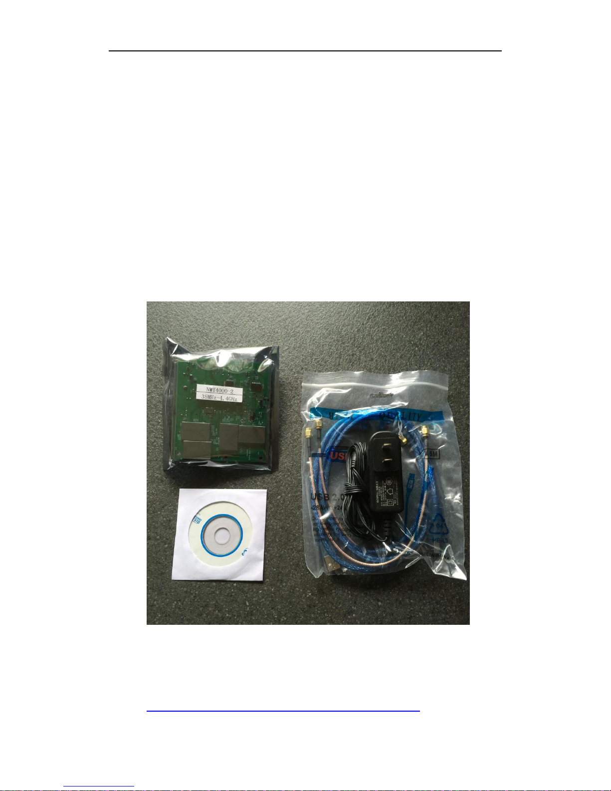
Instrument:
NWT Series sweep instrument 1PCS
USB cable 1PCS
AC (100-240V) to DC 12V power supply 1PCS
DISC 1PCS
SWR BRIDGE (OPTION not included) 1PCS
40db ATT (OPTION not included) 1PCS
6db ATT (OPTION not included) 1PCS
The version with improved screening as shown above was
purchase from cart100
http://www.cart100.com/Product/40865867643/

7

8
Technical characteristics (comparison chart to other products by WUTONG ELECTRONIC)
The basic parameters
type
frequency
step
log
line
power
att
ALC
NWT25-EX
2k-25M
1Hz
>70dB
no
12V/0.4A
0-50dB
no
NWT25-USB
2k-25M
1Hz
>70dB
no
USB(5V/0.4A)
0-50dB
no
NWT70-EX
50k-85M
1Hz
>70dB
0-0.7VRM
S
12V/0.4A
0-50dB
yes
NWT70-USB
50k-85M
1Hz
>70dB
0-0.7VRM
S
USB(5V/0.4A)
0-50dB
NO
NWT150-EX
50k-300M
1Hz
>70dB
0-0.7VRM
S
12V/0.4A
0-50dB
yes
NWT150-USB
50k-300M
1Hz
>70dB
0-0.7VRM
S
USB(5V/0.4A)
0-50dB
NO
NWT500-DDS
50k-500M
1Hz
>60dB
0-0.7VRM
S
12V/0.5A
0-50dB
no
NWT500-PLL
+DDS
50k-500M
10Hz
>60dB
0-0.7VRM
S
12V/0.5A
0-50dB
yes
NWT3000
138-3000
M
1kHz
>50dB
NO
USB(5V/0.4A)
NO
no
NWT4000-1
138-4400
M
1kHz
>65dB
NO
12V/0.5A
NO
NO
NWT4000-2
35-4400M
1kHz
>65dB
NO
12V/0.5A
NO
NO
Note: All the sweepers input port has maximum power: 10dBm
(not to exceed this power level, otherwise it may cause damage to the
detection device requiring return to factory for repair). If a need exist to
apply power level of more than 10dBm, use external attenuator.
The system accuracy
Frequency accuracy: can be calibrated to the smallest step accuracy:3ppm
Frequency stability: 3ppm/year
Power measurement error: + -2dB
The physical characteristics (a typical example amongst all types)
Dimensions: L*W*H=113.5*92.5*30 (a typical example)
Weight: 75g (a typical example)
Working temperature: 0 ℃ to +40 ℃

9
Installation and storage
Conditions of use
NWT series digital virtual frequency sweepers are using USB or external DC
12V power supply, and need to be kept away from strong radiations (high power switching
power supply, high power RF emission).
Operation temperature: 0-40 degrees centigrade.
Preheating:
NWT series digital virtual frequency sweepers are most accurate after 30 minutes
preheating prior to measurement.
Storage
Clean up the NWT series digital virtual frequency sweeper container, filled with
desiccant, can be stored at ambient temperature -10 to +50 ℃.
10
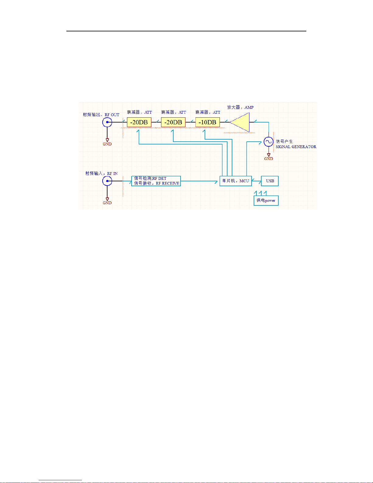
The basic design
Hardware configuration
1.1:
Theory:
The block diagram only for reference, some sweepers does not have att. and
amplifier.
The NWT4000-2 contains addition circuitry such as two PLL signal generators but
does not contain any attenuators or Amplifier.
1.2
Hardware connect
With the DC-12V and RS232/USB connected, external devices are connected
to the SMA connectors. (If the power supply method is via USB, as for other type of
products, you only need to connect the USB plug but the NWT4000-2 uses external
DC-12V supply)
NOTE: The supply must we a clean source and voltage can be reduced to 8V to
reduce temperature of the 5V regulators cooling fin, which else being quite hot.
The power connector shall be with positive center.
11
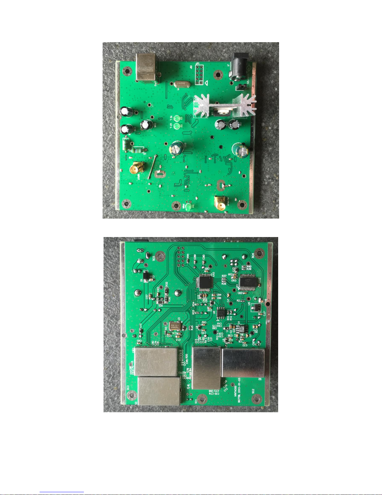
Top view (note new position of SMA Input and Out)
Bottom view (with latest improved screening)

12
The hardware connection reference map
The software guide
Software installation and configuration.
Dependent your operating system, the USB driver might be installed automatic. Let the
computer search on the Internet and it might take several minutes.
Otherwise find on the supplied disk relevant drivers:
If not installed automatic then:
Install USB driver by running ftdi_ft232_drive.exe for WIN7, WIN8 or use
inf file install driver.
Double click install USB driver
1.1 WINNWT
Install WINNWT software
first ,
second
After installing the WINNWT, the attribute shortcuts on the desktop can be modified
to support a number of languages as described below.
Right click on the shortcut and select properties and perform the modification as
described.
However, you may experience problem installing the software supplied on the Disk due
error messages. Copy the two zip files to your hard disk and unzip those, and remove the
Chinese character in the folders/filenames. That worked for me to install the 4.09 version
and the 4.09.07 update. In any case it is recommended to use the latest published version
4.11.09 of WINNWT from below link, as several more and improved features available:
http://www.dl4jal.eu/hfm9.htm. That version used for this documents screendump.

13
Original Chinese startup settings (remark the app cn.qm extension to winnwt4.exe)
The line “G:\Program Files\AFU\WinNWT\winnwt4.exe" app_cn.qm
Changed to:
“G:\ProgramFiles\AFU\WinNWT\winnwt4.exe” app_en.qm available
close and restart the program and the English menu is available.
The use of English version recommended but Chinese cn), Spanish (es), Hungary (hu),
Netherland (nl), Polish (pl) and Russian (ru) language may be chosen. The native German
language requires no extension after winnwt4.exe” (the “ required before and after the
path as shown)
1.3.
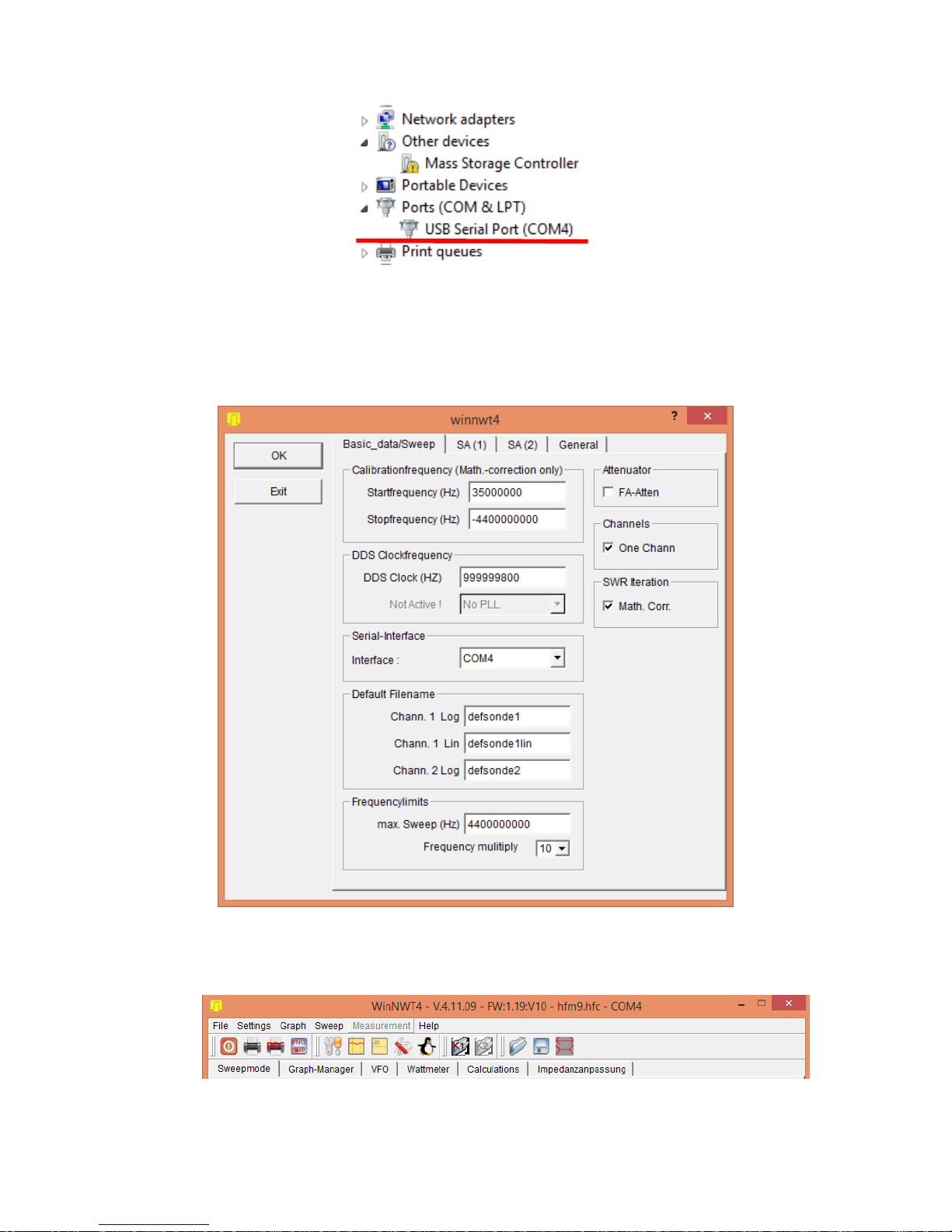
Setting COM port
Insert the USB into the computer.
Because USB driver is already installed, in the device manager you will find the
corresponding COM port and the allocated port number.
14
The port number to remember in this case is COM4.
When installing the driver, on different computers the COM port number will be differ
ent
In WINNWT software "Settings", "Options", select the corresponding COM
port, and click "OK".
Select COM port
Choose the correct com port and if successful, you will see the hardware firmware
version. Otherwise, check the connection and incorrect settings.
Correct prompt after selection of the correct COM port
15
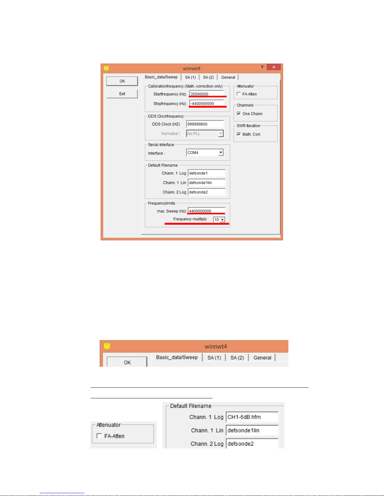
When using NWT3000, NWT4000-1 or NWT4000-2, you must set frequency multiply to 10
rate in Settings/Options.
Note the settings for start and stop frequency where stop is negative. Note also the max sweep
setting. If One Chann. tickmark in Channels is removed then you have two channel operation, e.g.
quite handy to have two different calibrations in actions. Also select Math. Corr. to allow SWR
itteration.
1.1 Functions not supported for NWT1400 in the WinNWT software by DL4JAL
The WinNWT software developed by DL4JAL was for another project and has a number of
function not supported by the NWT4000 family of products. These are:
- In the Settings Options a number of fields are not supported:
Only Basic_data/Sweep is supported. SA(1), SA(2), General has no functions
Attenuator has no function. Channel. 1 Lin not supported (only Log).
Remark file name for Channel 1 and Channel calibration files can be entered in
the text field so in use when program started. (here CH1-6dB.hfm)
16
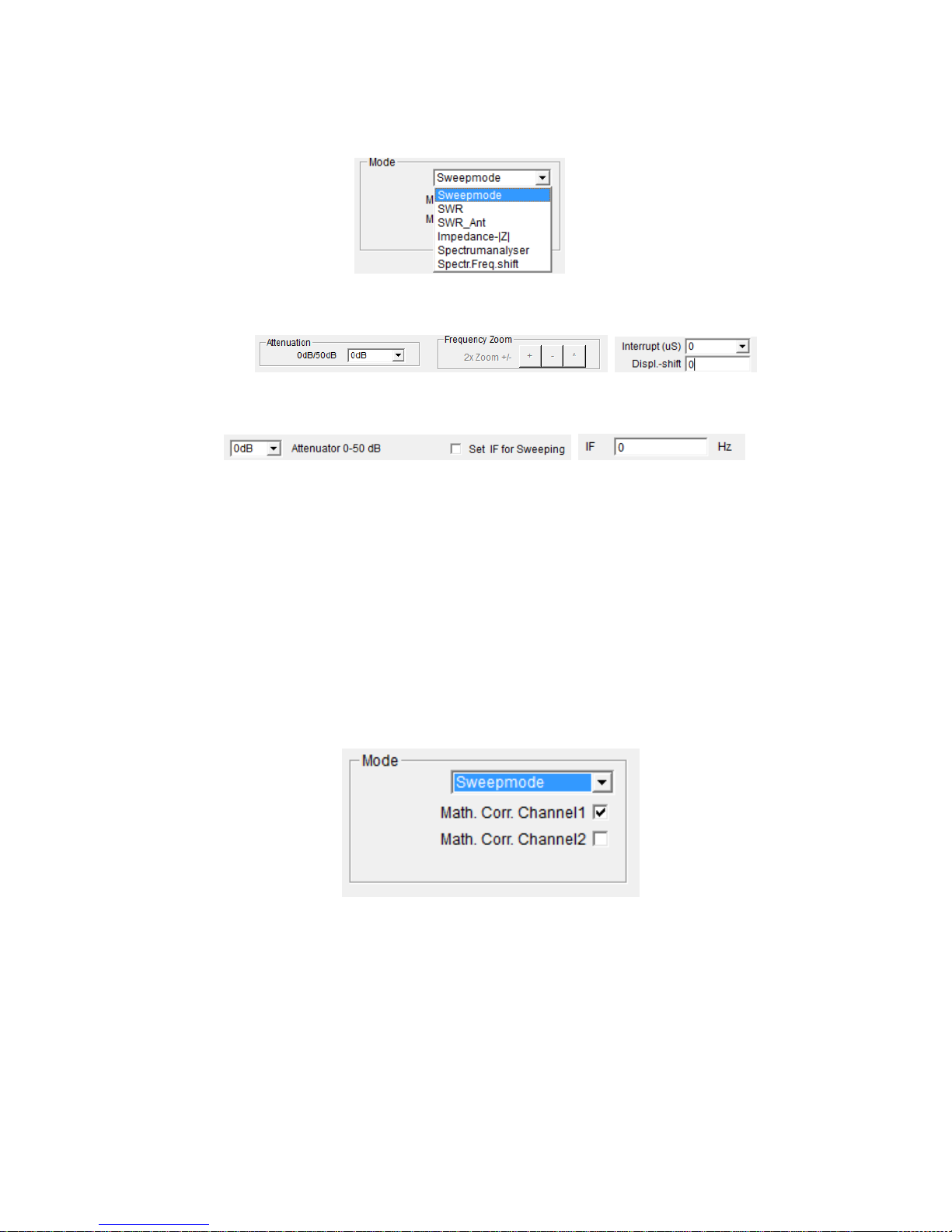
- In the mode selection box under sweepmode only sweepmode, SWR and
Impedance-|Z| is supported. The remaining selection cannot be used as they are.
Attenuation and Frequency Zoom cannot be used.
Display shift OK for the dB Y Axe. Interrupt (uS) = rest time for each sample
-
- For the Graph-Manager all functions supported
- For VFO: Attenuator 0-50dB , Set IF for Sweeping and IF setting has no function.
- For Wattmeter the VFO on/off does not stop the output but allows to type remarks
and save these. Do not save in the application path but under a folder of your
choice as else hidden for later retrieval.
- The calculations and Impedanzanpassung (impedance matching) are with no
comment.
2
Logarithmic Y scale sweep frequency settings
2.1
Select the sweep frequency mode
Select the sweep frequency mode
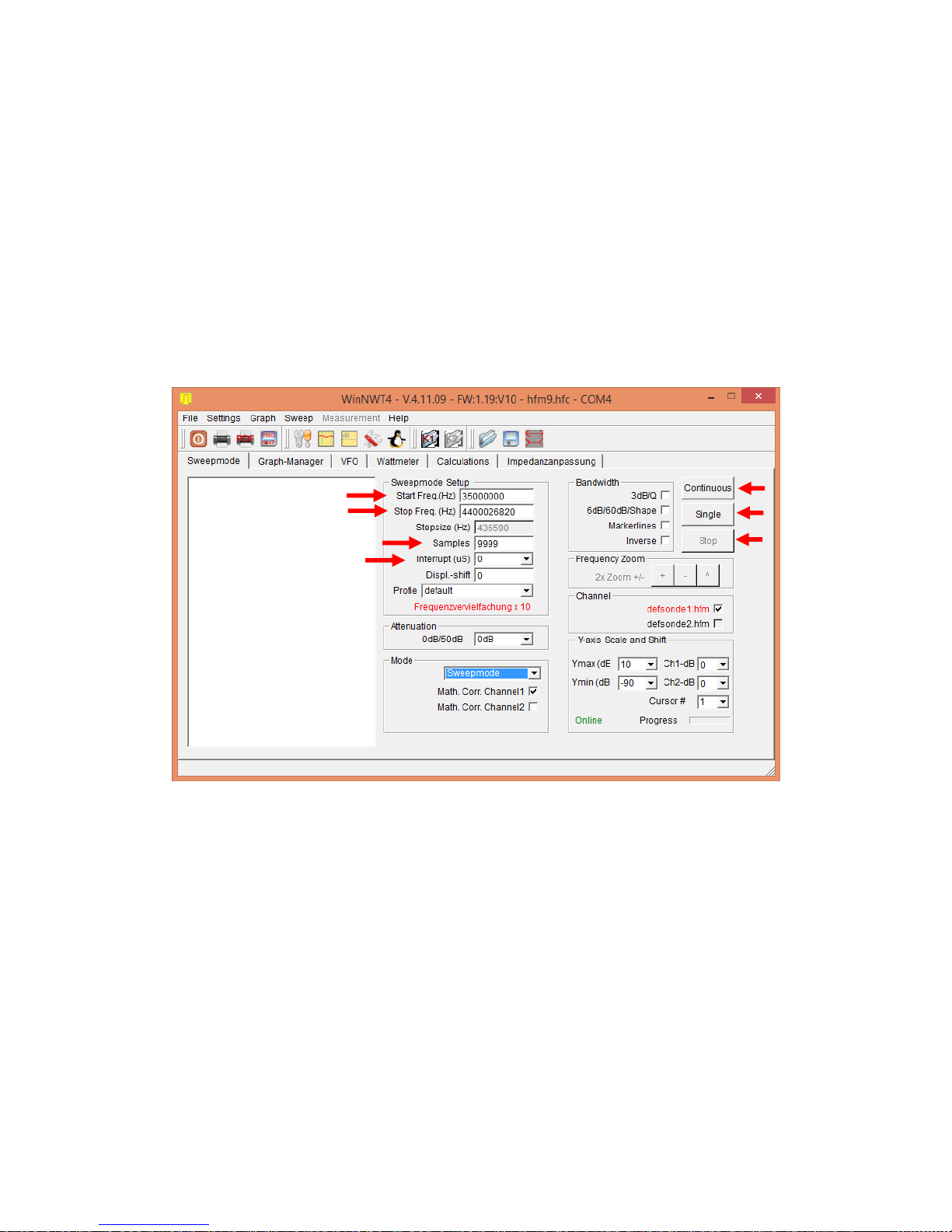
2.2 Set the frequency parameter
Enter the start frequency, the end frequency, scanning numbers / number of
samples for a scan. There are two kinds of scanning modes, a continuous scanning
where the number of samples (max 9999) are being scanned, until final sample to
stop scanning is measured.
17
Another is the single scanning where only one scanning performed for the number
of samples. For changing frequency settings, scanning numbers/number of samples
and other parameters, you must click on Stop before change settings.
The scan delay for each point/sample of the output frequency, are long latency
for power measurement.
Enable the Math. Corr. Channel1 (and Channel2 if enabled)
Y scale and Shift can only be set, provided the scan is stopped.
Attenuation is not applicable for the NWT4000 models
Other possible settings to be explained in later sections of this document

18
2.3 Before starting measurement the Instrument should be calibrated.
It is recommend to initially using the software on the supplied disc called COM assiter.exe.
It performers an excellent flat calibration of you particular hardware and the result is saved
into the hardware. However the levels from -10dB to 0dB is nonlinear due to about 4dB
compression in the internal reception mixer and/or logarithmic detector. The -40dB level is
calibrated and consequently the -10, -20 and 30dB level are not fully accurate. It applies
also for all levels below -40dB. This problem can be eliminated by inserting a 6dB
attenuator in the Output path (mounted on the SMA TX output at all times) but this
however reduces the dynamic range by 6dB. As the WinNWT software also have
calibration routines, which is allowing the top level calibration, to be performed at a user
selected lower level this 6dB attenuator is only used during calibration within the WinNWT
software and removed after calibration. Then the full dynamic range is available with the
only limitation that 0dB level is compressed to about -3dB but from -10dB and downwards
everything is perfect. If the device tested has an insertion loss above 3-4dB then the
compression has no effect. If not so then use a 6dB att. permanently and accept the 6dB
loss of dynamic range and create a different calibration.
The WinNWT software can save as many calibration files as you wish so just find you own
way.
The initial calibration being the platform the WinNWT calibrations is described in the
document “Calibration step_UK.pdf” published same public places as this document. The
documentation also added as Appendix to this document. It also contains a frequency
calibration method, which works nicely and allows 1KHz setting at 4.4GHz (but that
stability not maintained over time or temperature changes).
The frequency calibration is performed at 1GHz and the measured output frequency just
entered in the WinNWT DDS (PLL) clock field, as seen previously above on page 12 as
999999800Hz. Tricks a possible to use a 100MHz counter as described in said document
and the Appendix.
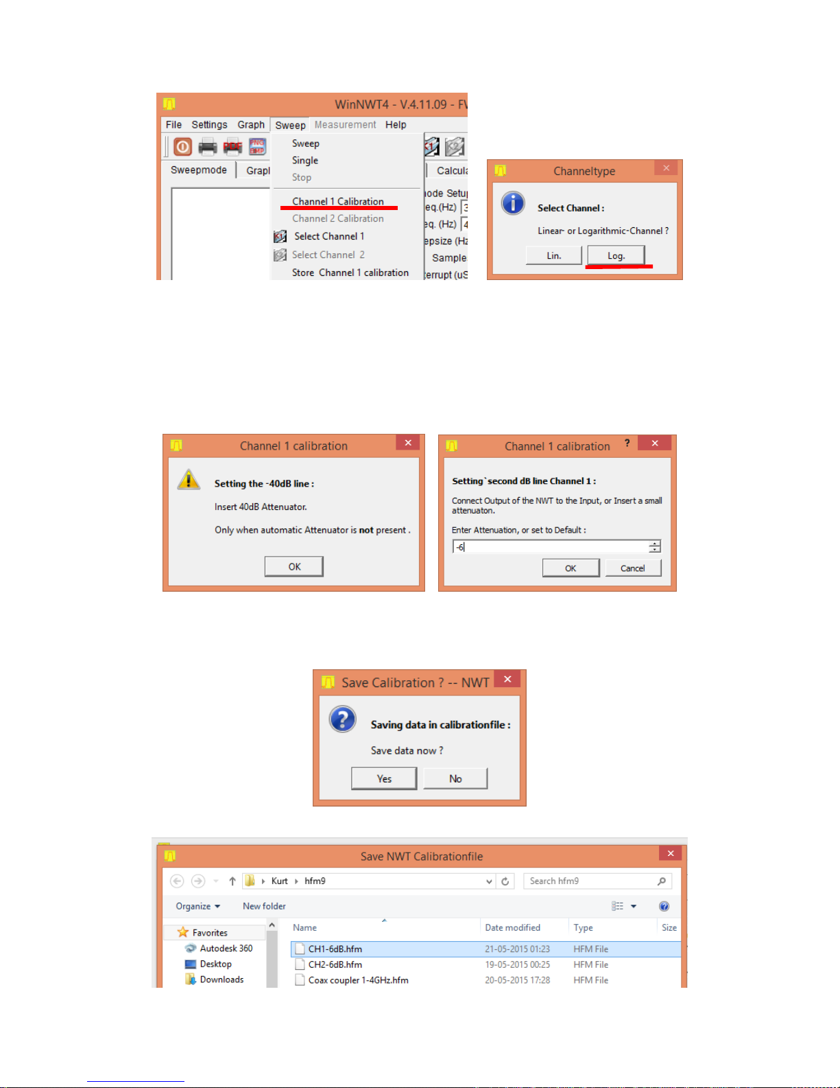
A WinNWT calibration performed as follows
Select Channel 1 Calibration and subsequently Logarithmic Channel (Lin does not apply
for NWT4000 hardware):
19
Insert a 40dB attenuator in the Transmit path (at the SMA Output) and click OK
Subsequent you are promptedd to insert a 0dB attenuator or select differently a user
defined att. here stepped down to -6dB. The sweep is performed automatic with 9999
samples.
Then you are asked to save the calibration or not.
(if not then only in force as long the NWT4000 switched on)
A file name selected here CH1-6dB.hfm
20
When accepted by a click on OK the trace is jumping to it correct position -6dB. If Y
scaling change to 0 and -10dB we see it bang on -6dB (small image below)
If we enter the 40dB att. and run a single scan, we will see it is flat on -40dB from 35MHz
to 4.4GHz
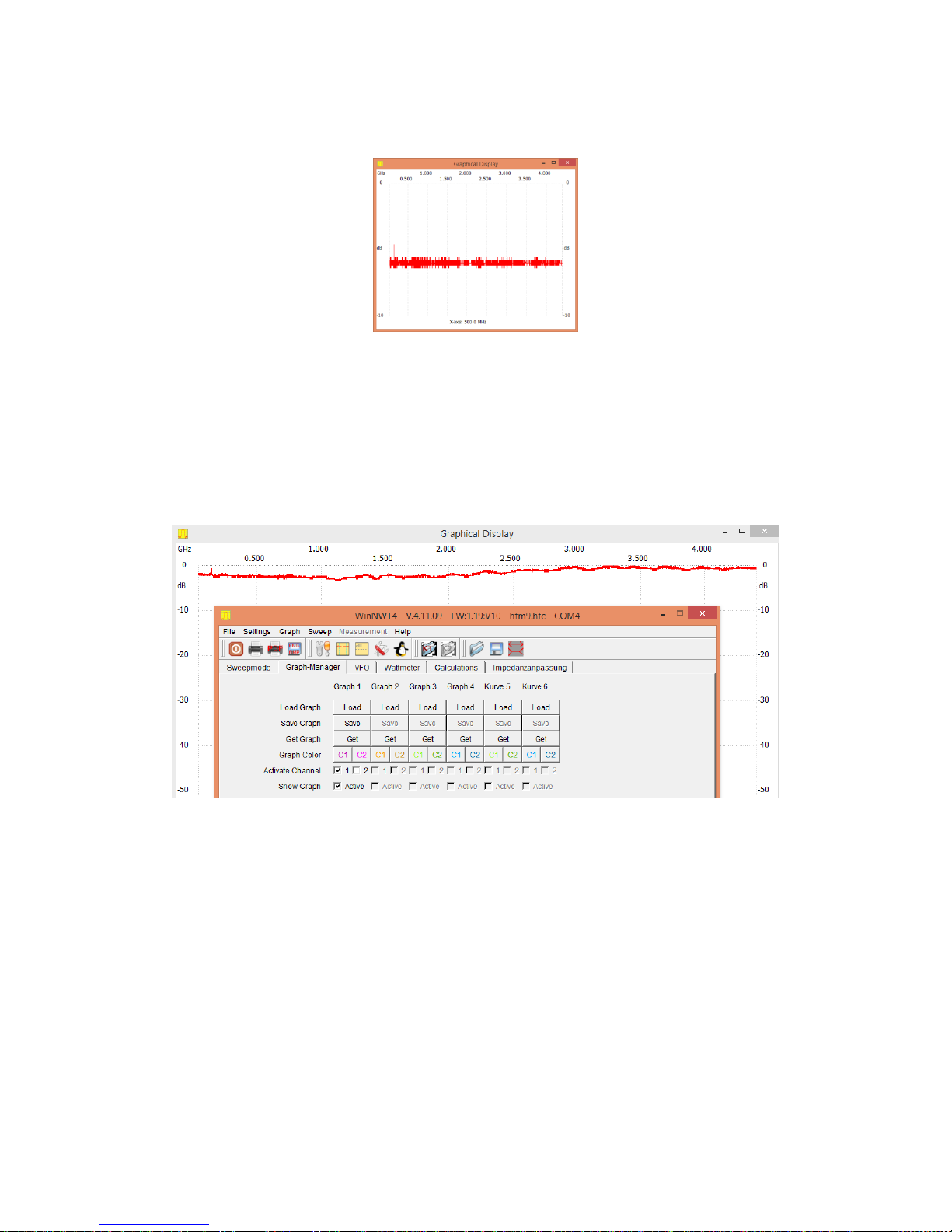
If we connect the Output and Input directly and run a sweep we see the degree af
compression in the mixer. Below 2GHz it is about max. 2.5dB and above 2GHz it is
reduced to less than 1 dB. By clicking on Graph Manager we can maintain the sweep by
clikcing on Get and enable tickmark Active Channel 1 and Active as shown. Thus we can
have up to 6 traces for ch1 on the screen in addtion to the current run sweep.
As can be seen below the linearity is quite excellent and the noise floor pretty low

21
2.4 Blending cursor data into the trace image and saving it
It is possible to blend cursor data into the trace image. First of all press the numeric
key from 1 to 5 on the keybord and click on the frequency position where you want the
particulator cursor number to be placed. When so done select in the main menu File /
Speichern als Bild (store as image). When next screen promt apears enable tickmark
“Info einblenden” and with X and Y position, place the information where you want it.
You may also change letter size with Schriftgroesse. When you click on the “Bild
speichern” you can save the image to harddisk incl. the data information as shown
below.
22
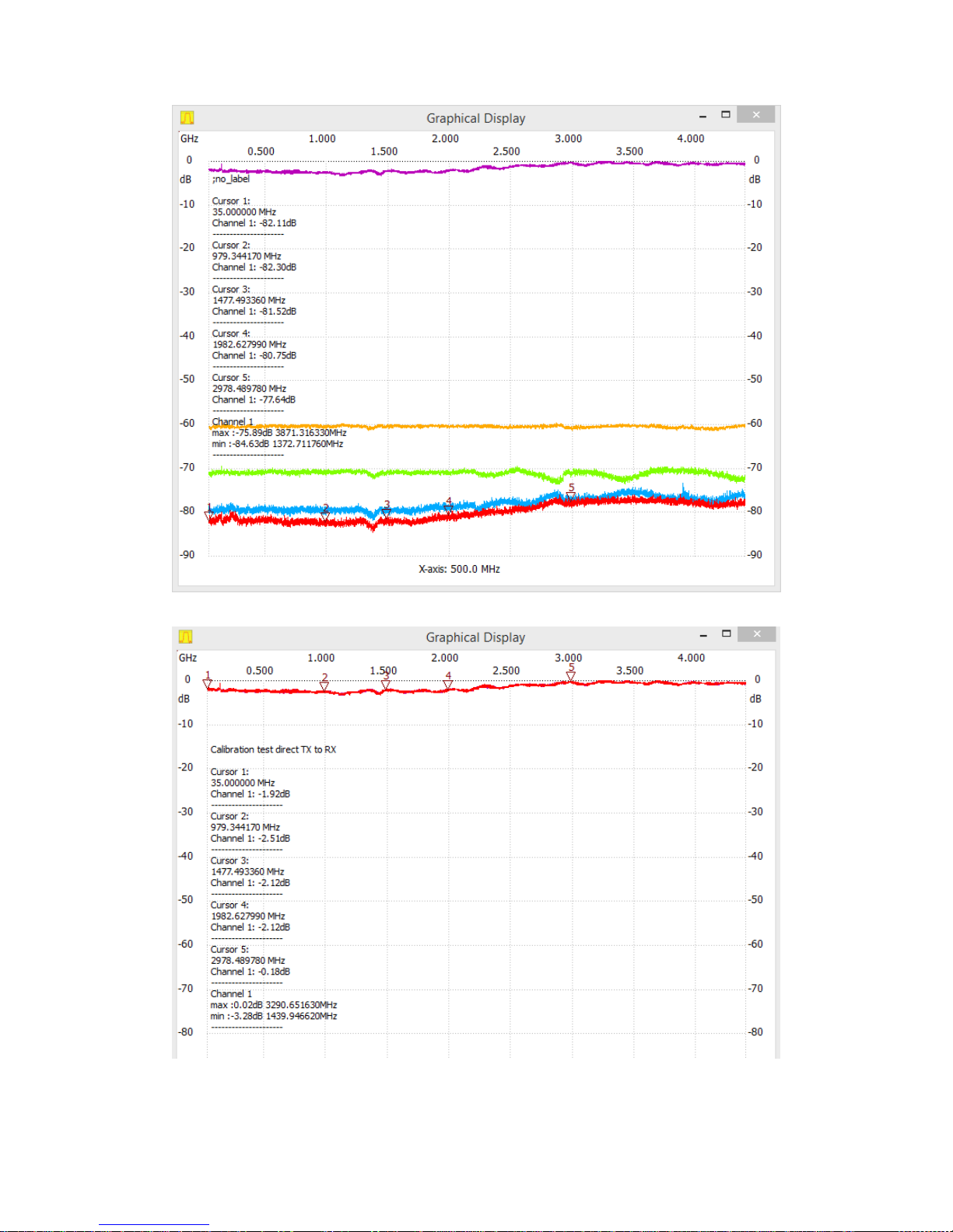
You may edit first line ;no_label prior to “einblenden” as seen on the next image below.
23
Above measurement done with two 5cm long male SMA SMA cables connected from
the PCB SMA connector to a front panel with female female SMA adaptors used as
the TX and RX connections. As previous described the NWT4000-2 has best
dynamic range if mounted in a plastic case. Below plot shows a calibration performed
without these two 5cm MSA SMA cables and the female female adaptors, thus directly
at the PCB SMA adaptors and the dynamic range even better manintaning 80dB to
4.4 GHz.
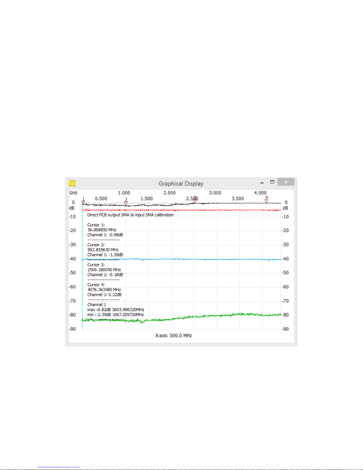
To utilized the NMT4000-2 to the extreme two male female SMA adaptor might be a
possiblity to get the Input and Output to penetrate the case on the top and let the
cooling fin be exposed to the ambient.
The black trace for Input and Output directly connected shows below 3GHz up to 2dB
loss off signal amplitude due to mentined compression in the internal mixer and/or
logarithmic detector. If the DUT has insertion loss more than 2 dB it has no effect.
 Loading...