

Wurth Online World COOLIUS 4000 HP, W050200011 User Manual
User’s manual
COOLIUS 4000 HP automatic a/c service unit
Art.-No.W050200011
2154-ENG / Version 02/2014


CONTENTS
Safety precautions ................................................................................................................................................................... 2
Layout drawings ..................................................................................................................................................................... 3
Hydraulic diagram .................................................................................................................................................................. 5
Electric diagram ...................................................................................................................................................................... 6
Legend .................................................................................................................................................................................. 7
1 Introduction to recovery unit COOLIUS-HP ........................................................................................................................ 8
1.1 Technical specifications ................................................................................................................................................ 8
2 Components description and standard equipment .............................................................................................................. 8
2.1 High vacuum pump ..................................................................................................................................................... 8
2.2 Refrigerant charging pump ........................................................................................................................................... 8
2.3 Refrigerant bottle ......................................................................................................................................................... 8
2.4 Distiller/Separator ........................................................................................................................................................ 8
2.5 Compressor ................................................................................................................................................................ 9
2.6 Filters drier .................................................................................................................................................................. 9
2.7 Flexible hoses .............................................................................................................................................................. 9
2.8 Quick coupler valves .................................................................................................................................................... 9
2.9 Printer ......................................................................................................................................................................... 9
2.10 Control module ........................................................................................................................................................... 9
3 Preparing unit COOLIUS-HP for operation ...................................................................................................................... 11
3.1 Checking the vacuum pump oil level ........................................................................................................................... 11
3.2 Turning COOLIUS-HP unit on for the first time ............................................................................................................. 11
3.3 Filling refrigerant into the internal bottle ...................................................................................................................... 12
4 Using unit COOLIUS-HP .............................................................................................................................................. 13
4.1 Refrigerant recovery ................................................................................................................................................... 13
4.2 Vacuum + Vacuum Test ............................................................................................................................................. 14
4.3 Olio / Uv – Refrigerant charge .................................................................................................................................... 14
4.4 Automatic cycle ......................................................................................................................................................... 16
4.5 Flushing .................................................................................................................................................................... 18
4.6 Checking the A/C system operating pressures .............................................................................................................. 19
4.7 Disconnecting the unit from the A/C system ................................................................................................................. 19
4.8 Setting Menu ............................................................................................................................................................. 19
5 Service procedures ...................................................................................................................................................... 21
5.1 Emptying the internal refrigerant bottled ...................................................................................................................... 21
5.2 “Zero” scale check ..................................................................................................................................................... 21
6 Routine maintenance ................................................................................................................................................... 22
6.1 Material for routine maintenance ................................................................................................................................ 22
6.2 Periodic operations .................................................................................................................................................... 22
6.3 Changing the vacuum pump oil .................................................................................................................................. 22
6.4 Replacing the filter drier ............................................................................................................................................. 23
7 Troubleshooting .......................................................................................................................................................... 25
8 Accessories and spare parts .......................................................................................................................................... 26
9 Weight and dimensions ................................................................................................................................................ 26
1 - 32

Safety precautions
This equipment is designed for trained personnel only, who must know the refrigeration
fundamentals, cooling systems, refrigerants and possible damage that pressurized equipment may
cause.
Only use refrigerant R134a. The unit must not be used with a different refrigerant than the one it has
been designed for.
Carefully read the instructions contained in this manual; strict observance of the procedures
described is fundamental to the operator’s safety, the perfect state of the unit and constant
performances as declared.
The unit must always work under the operator’s direct supervision
Before performing any operation, make sure that the hoses used for connections have been
previously evacuated and that they do not contain non-condensable gases.
Avoid skin contact; the low boiling temperature of the refrigerant (about -30°C) can cause freezing.
Avoid breathing refrigerant vapours.
It is recommended to wear suitable protections like safety glasses and gloves; contact with refrigerant
may cause blindness and other personal injuries.
Do not smoke near the unit and do not operate near open flames and hot surfaces; the high
temperatures decompose the refrigerant releasing toxic and caustic substances which are hazardous
for the operator and the environment.
Always make sure that the unit is connected to a suitably protected mains supply provided with an
efficient earth connection.
Before performing maintenance operations or when the unit will not be used for a long period of
time, turn the unit off by turning the main switch to 0 and disconnect the power supply cord;
absolutely follow the sequence of operations.
Operate the unit only in locations with suitable ventilation and a high number of air changes.
Before disconnecting the unit, make sure that the cycle has been completed and that all valves are
closed in order to avoid release of refrigerant to the atmosphere
Never fill any tank with liquid refrigerant to more than 75% of its maximum capacity.
During operations avoid release of refrigerant to the environment; this precaution is required by
international environmental standards and is essential to avoid difficult leak detection in a refrigerant
polluted environment.
Protect the unit from dripping.
Do not expose the unit to direct sunlight, rain and to the inclemency of the weather.
Do not modify the calibration of safety valve and control systems.
If you recover refrigerant from a cooling system equipped with a water evaporator and/or condenser,
it is necessary to drain water from the evaporator and/or condenser or to keep the circulation pump
running during the entire recovery operation in order to avoid frosting.
Disconnect the unit from the power supply if not used.
General information
Perform a good vacuum cycle before charging refrigerant into the system!
Perform the refrigerant charging phase after having charged oil or UV!
Empty the used oil bottle before starting the recovery phase!
WARNING
If you do not pay attention to the above safety precautions, you could damage the recovery unit and the
car A/C system!
!
2 - 32
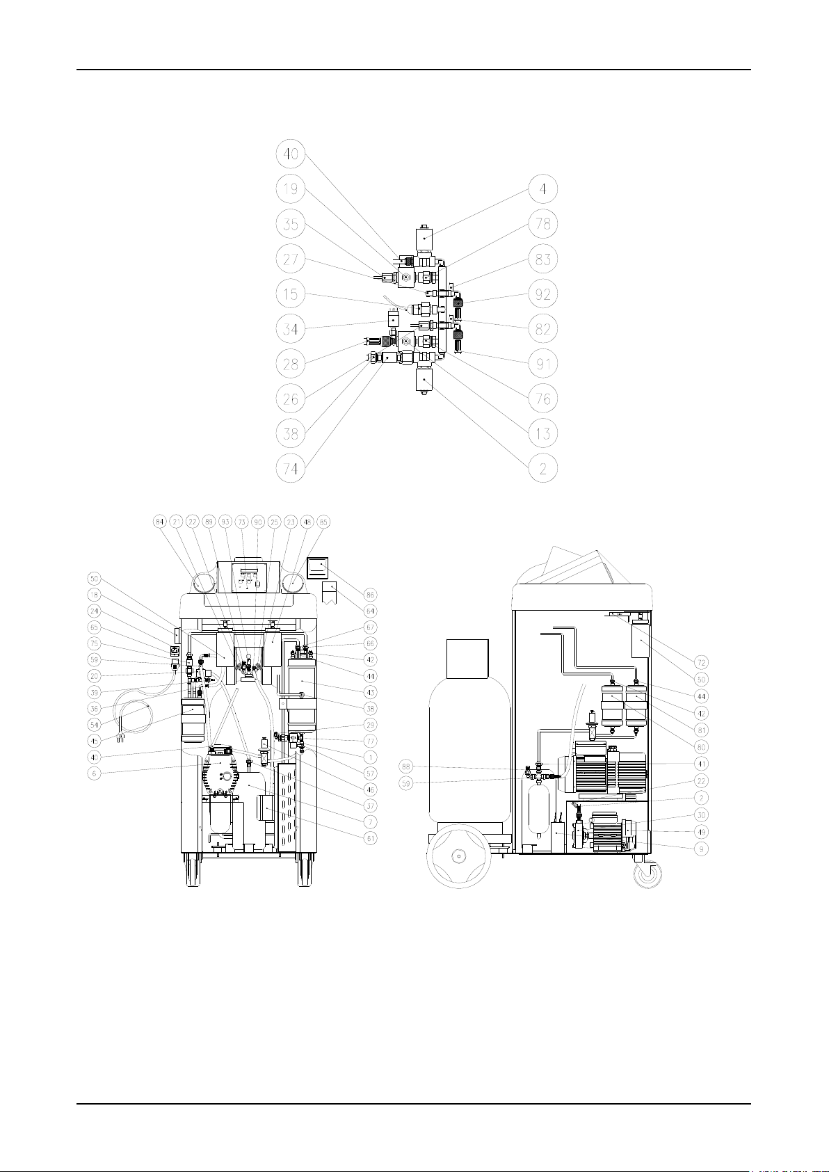
Layout drawings
Picture 1
3 - 32
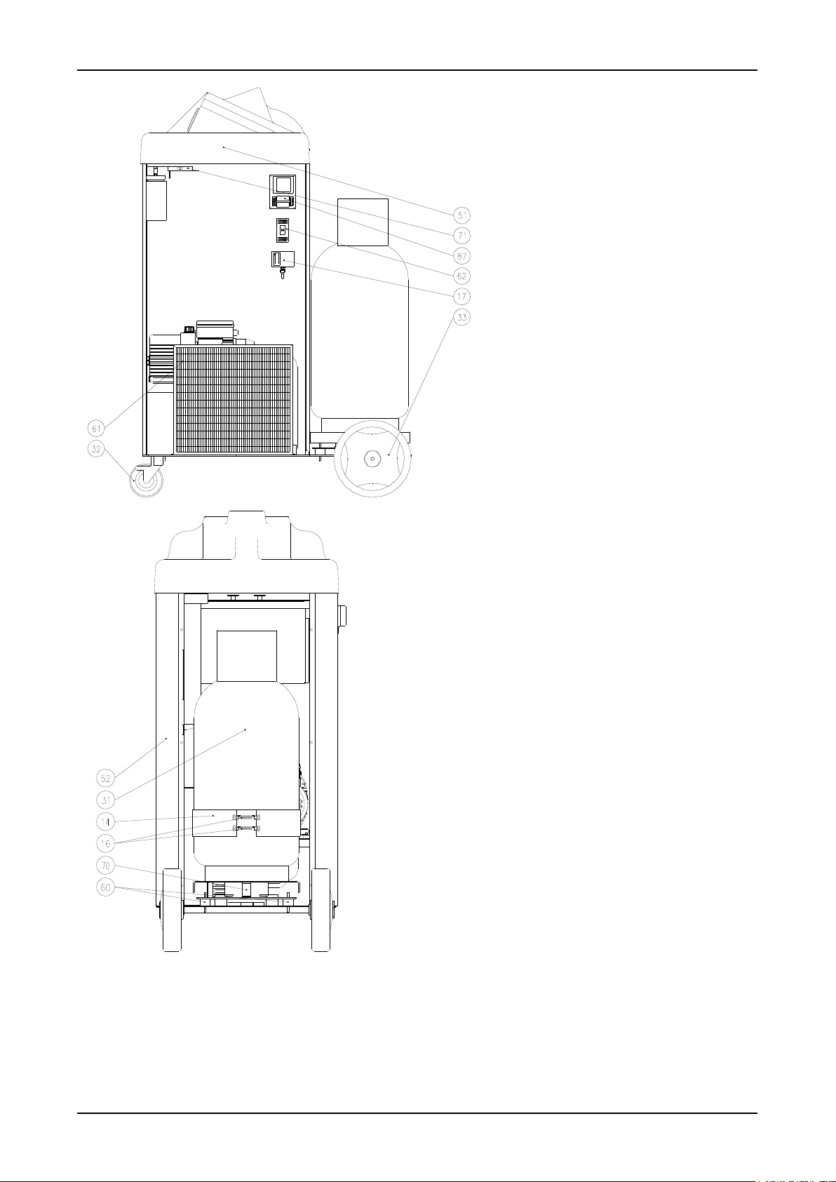
Picture 2
4 - 32
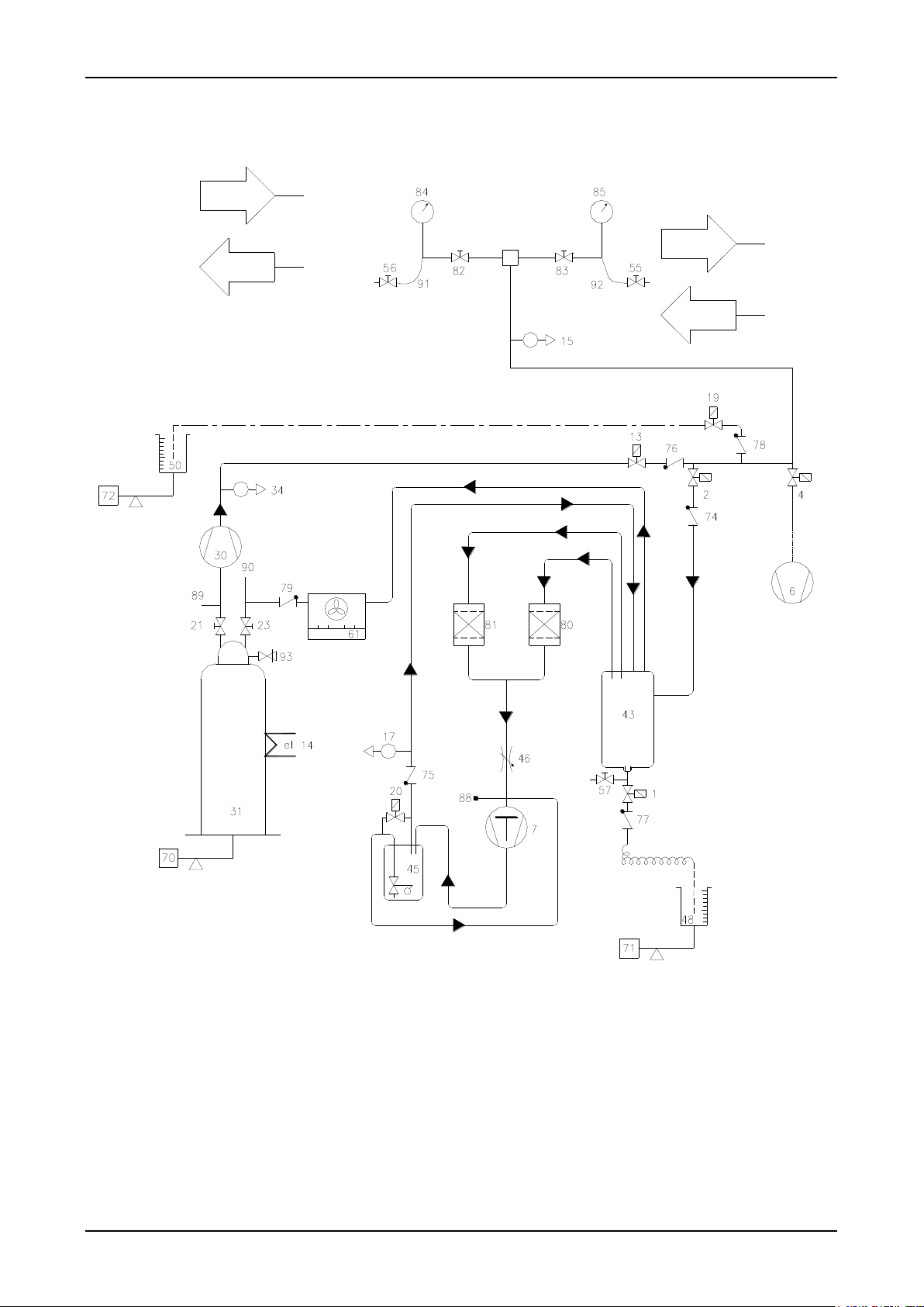
Hydraulic diagram
Picture 3
5 - 32
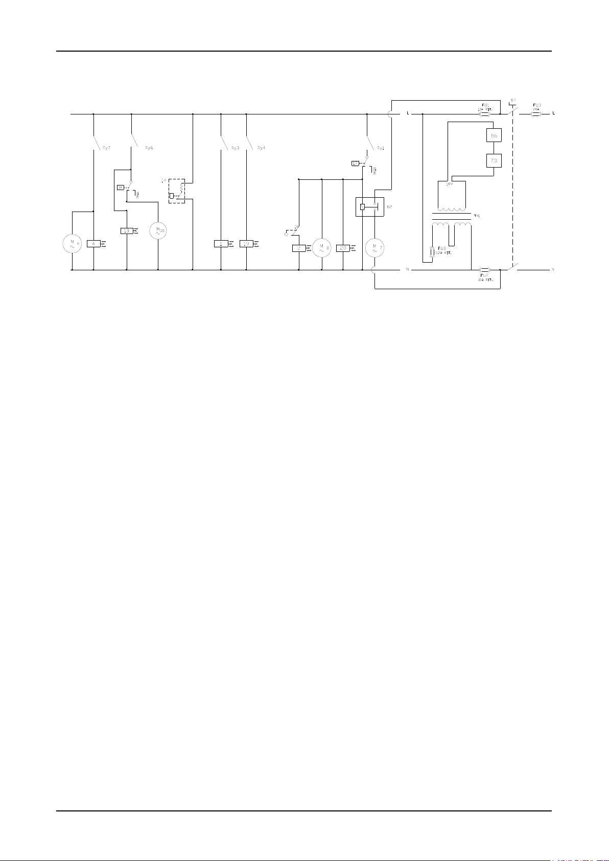
Electric diagram
Picture 4
6 - 32
1
Solenoid valve – oil discharge line
48
Oil discharge bottle
2
Solenoid valve - recovery line
49
Refrigerant charge pump
4
Solenoid valve - vacuum line
50
Oil/UV charging bottle
6
Vacuum pump
51
Plastic cover
7
Compressor
52
Frame
9
Compressor starting condenser
53
Front door
10
Vacuum pump oil filler plug
54
Power cable
11
Vacuum pump sight glass
55
HIGH quick coupler
12
Vacuum pump oil drain plug
56
LOW quick coupler
13
Solenoid valve - refrigerant charging line
57
Manual discharge valve on the distiller
14
Heater belt with thermostat on the bottle
59
Oil return hose to compressor
15
Pressure transducer
60
Vibration damping feet on the scale
16
Spring for heater belt
61
Condenser with fan
17
Safety pressure switch
62
Remote control witch for recovery compressor
18
Main power switch
64
Thermal paper roll
19
Solenoid valve - oil/UV charging line
65
Fuse on outlet (10A)
20
Solenoid valve - pressure return to compressor
66
Distiller coil inlet tube
21
Liquid valve on the bottle
67
Distiller coil outlet tube
22
Refrigerant charge hose (bottle-pump)
68
Rear door
23
Vapour valve on the bottle
69
Handle
24
Power outlet (with fuse)
70
Load cell - 100 kg (refrigerant)
25
Condenser / bottle connecting hose
71
Load cell - 5 kg (oil discharge)
26
Capillary hose connecting LOW valve to LP gauge
72
Load cell - 5 kg (oil charge)
27
Capillary hose connecting HIGH valve to HP gauge
73
Control board
28
Refrigerant charge hose (pump-valve block)
74
Check valve - recovery line
29
Oil discharge capillary tube
75
Check valve – compressor delivery line
30
Refrigerant charge pump motor
76
Check valve – refrigerant charging line
31
Complete refrigerant bottle
77
Check valve – oil discharge line
32
Front wheel with brake
78
Check valve – oil charging line
33
Rear wheel Ø 250
79
Check valve - compressor delivery line (condenser)
34
Safety pressure switch on refrigerant charging line
80
Filter drier
35
Oil injection capillary tube
81
Filter drier
36
Hose - pressure return to compressor
82
Manual valve - LOW
37
Compressor/compressor oil separator connecting
hose
83
Manual valve - HIGH
38
Valves assembly - distiller connecting hose
84
LP gauge
39
Safety switch capillary hose
85
HP gauge
40
Vacuum pump hose
86
Printer
41
Compressor suction hose
87
Electric feeder
42
Distiller/filter F1 connecting hose
88
Service connection for compressor evacuation
43
Distiller / separator
89
Bottle service connection
44
Distiller/filter F2 connecting hose
90
Bottle service connection (1/4” SAE)
45
Oil separator – complete compressor
91
LOW flexible hose
46
Flow regulation valve with hoses
92
HIGH flexible hose
47
Handle support
93
Safety valve
Legend
7 - 32
Model
Couplers and connections
COOLIUS-HP
1/4” SAE with quick couplers
1 Introduction to recovery unit COOLIUS-HP
Unit COOLIUS-HP permits quick and efficient recovery of refrigerant from the A/C system, refrigerant
recycling, system evacuation, check for tightness, additive or lubricant injection, the subsequent charge with
refrigerant and measurement of the operating pressures.
Unit COOLIUS-HP permits to control all functions by means of 3 electronic scales (Refrigerant, Discharged
Oil from A/C system, new Oil/Uv), 1 pressure transducers.
1.2 Technical specifications
Refrigerant R134a
Maximum storage capacity 40 kg
Refrigerant supply 4 kg
Maximum recovery rate 1,0 kg/min
Maximum oil capacity 500 g
Oil supply 50 g
Power supply 230/1/50
Power input 1400 W
Storage temperature -10 ÷ +50 °C
Working temperature 0 ÷ 40 °C
Protection degree IP24
Noise level < 70dB (A)
Maximum refrigerant charge The maximum refrigerant quantity available for charging is
calculated by subtracting 4 kg from the weight of the
refrigerant contained in the bottle and indicated on the
display
max kg for charging = kg in bottle - 4 kg
2 Components description and standard equipment
2.1 High vacuum pump
Essential component for extracting from the cooling system the residues of technical gases used for pressing,
ambient air and vapour contained in it as well as water possibly formed through vapour condensation. The
high vacuum pump the unit is equipped with is rotary vane type, lubricated by oil injection.
2.2 Refrigerant charging pump
Rotary gear pump enables to have high refrigerant charging rates
2.3 Refrigerant bottle
Maximum capacity kg 40
Weight of empty bottle kg 22
It is provided with two connections, one of which with tube (liquid refrigerant) and one without tube (vapour
refrigerant), safety valve and heater belt with thermostat. The non condensable gases discharge is controlled
automatically by the software.
2.4 Distiller/Separator
Single body construction, featuring:
Distillation chamber with automatic flow control
Separating chamber for the oil removed from recovery compressor and return
8 - 32
 Loading...