

WURGES HV 6 W Operation Instructions
E
10/99 1/4
vibrationmotors
HV 6 W
Instructions of operation
and
List of spares
Important remark concerning the personal safety of operators
These instructions must be understood by each operator,
who is in charge of the assembly, putting into operation,
maintenance and repair work of vibration motors. The same
applies to supplementary instructions for modified
equipment.
Our vibration motors have been manufactured in
accordance with the latest art. In case of use as provided,
they are sure to operate.
Unauthorized changes with the motors and specific
execution for the client are excluded from the manufactures
guarantee for resulting damage.
It is an implied feature of vibration motors that they
generate destructive forces. In case of improper use, these
destructivforces are apt to cause danger, e.g. the motor or
components thereof can drop uncontrolled after getting
loose from the fastening means. As a precaution, safety
measures must be adopted.
When performing maintenance or repair work, the vibration
motor must be disconnected from the power system.
Putting vibration motors into operation without protective
cover is forbidden, because risk of accident may result.
Instructions for mounting vibration motors
General
Vibration motors must be mounted only on equipment with
plane surfaces, which are resistant to bending. These
surfaces must not be subject to tensions.
Only screws of grade 8.8 and nuts of grade 6 must be used.
The screws must be secured from slackening, e. g. by spring
washers or the like.
Posterior tightening of screws and nuts
After the first two hours of operation the screws or nuts
must be checked for tight seating. Subsequent inspections
shall be performed once daily. In case of necessity the
screws or nuts must be retightened.
The minimum torques are for: M10 = 55 Nm
M12 = 90 Nm
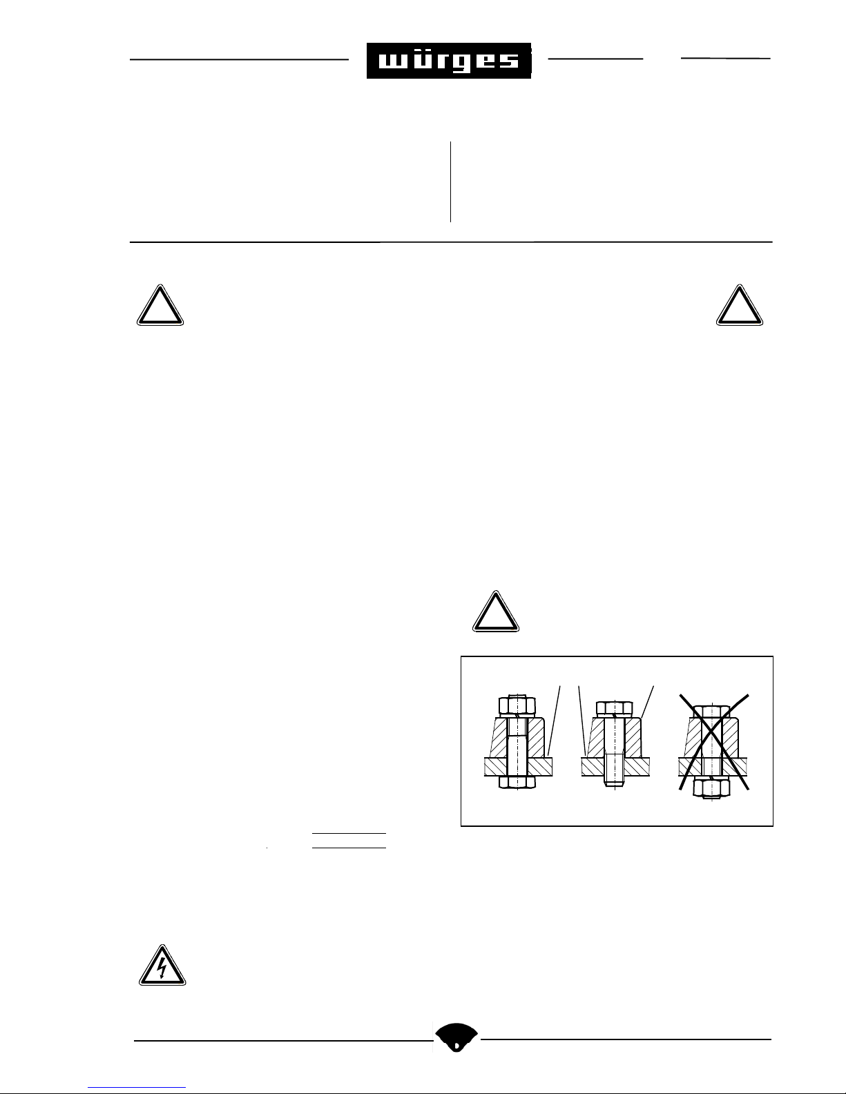
If the screws have slackened, danger of
breakage of the feet of the vibrator is
impending.
screwplate vibratorfoot
correct correct wrong
Anweisung zum elektrischen Anschluß
Dangerous Voltage!
Non-compliance can cause death, serious
bodily injury or property damage.
General
The power connection must be established only by an
electrician. The voltage and frequency must be that, which
is indicated on the machine plate (230 V , 50/60 Hz). The
vibration motor must be connected only to power supply
which is in agreement with the VDE regulations.
! !
!
10/99 2/4
To secure the motor from overload, it must be connected in
series with a terminal circuit breaker (1A).
Power connection
The power connection must be established only by a
flexible cable. We recommend to use the following cable
type: ÖLFLEX 540 P 2,5². Plastic cables are not suitable.
The connection cable must be laid in a manner which
excludes inherent vibrations and any load by traction.
Kunststoffkabel sind ungeeignet.
1. Kabelmantel ca. 8 cm entfernen
2. Den Schutzleiter 1-2 cm Länger belassen als die Adern
der Phasen.
3. Provide the ends of the strands with terminals or
compression cable sockets. Never fasten the terminals
or sockets by soldering, as in default of this the strands
tend to break behind the soldered spots in case of
vibration.
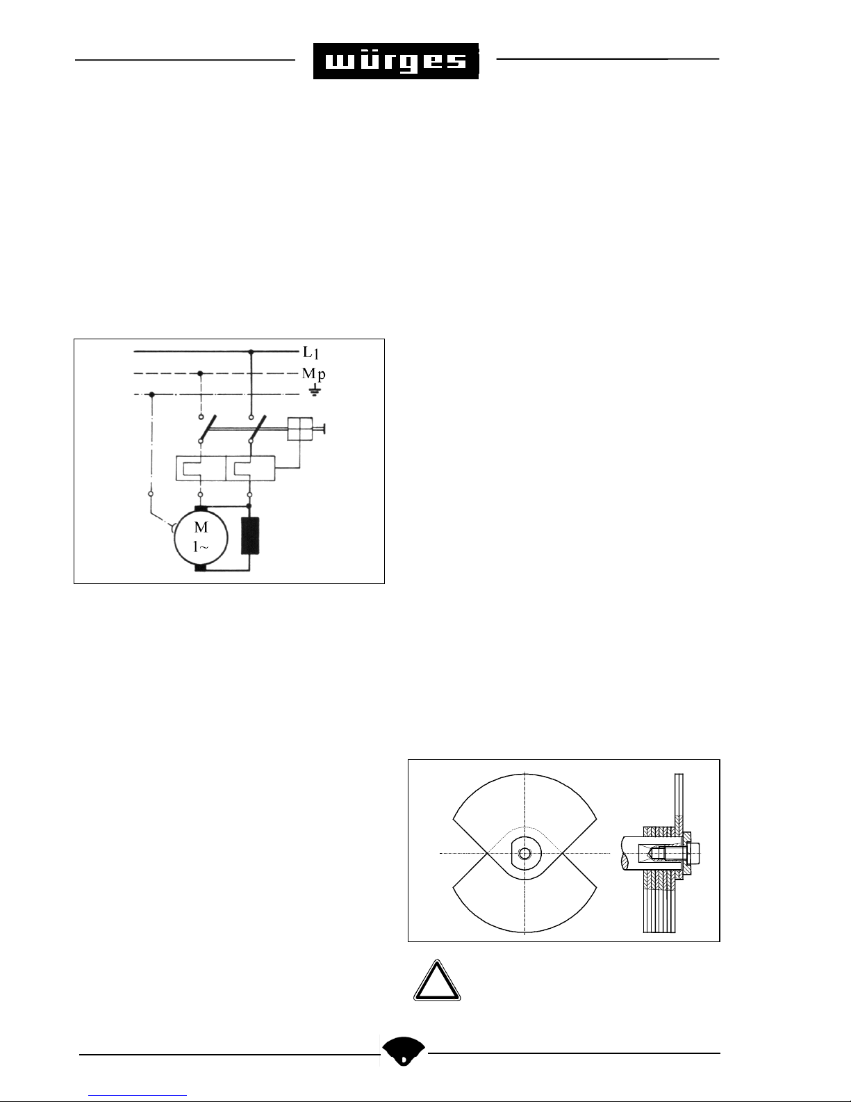
4. Introduce the cable into the the terminal box and
establish the connection as shown in the diagram.
5. When tightening the cap screw of the screw joint, it
must be observed that the cable jacket is still fully
seized by the seal. If this is not observed, the cable is
not firmly clamped, not relieved from traction, and not
waterproof.
6. Close again carefully the terminal box with seal and
screws..
7. The power cable must be fastened firmely shortly
behind the cable gland. This first fastening of the cable
and the motor should by no means be movable against
each other. The cable has to be installed in such a way
that it does not start vibrating itself and that it is not
subject to any tractional forces.
8. When putting the vibration motor into operation the
power input must be examined. Should this be larger
than the data on the mashine plate, the trouble can be
remedied by reducing the centrifugal force.
9. Now and again it must be checked that there are no
spots which are subject to friction.
Admitted operating temperature
Outside on the housing not higher than 80°C.
This limit may be surpassed by too high a power input, if
the speed which is indicated on the mashine plate is not
reached, with the result that the winding may burn out. The
reason may be too high a centrifugal force for the case
which is existing or a construction of insufficient resistance
to bending. The trouble can be set by reducing the
centrifugal force.
Setting the centrifugal force
Provide that no different centrifugal force had been
indicated in the order sheet, the motor has been set for the
full centrifugal force. In order to be able to change the
centrifugal force both protective covers must be taken off.
Once the protective covers are taken off, the centrifugal
force may be changed as desired. But it must be observed
that the adjustment is the same on both sides.
This is achieved by removing the screws or nuts from the
armature on both sides and by transposing the flywheels by
180°. With this the centrifugal force is reduced by twice the
value of the transposed flywheels. But in the case, the
removed flywheels must be replaced by spacers. (Please
compare the corresponding list of spares).
One flywheel on each side generates a centrifugal forces of
65 daN at 5000 min
-1
.
Nach dem Verstellen müssen gelöste
Schrauben wieder befestigt werden und die
Schutzhauben unbedingt wieder montiert
werden. Ansonsten besteht Unfallgefahr.
!
 Loading...