

Page 1

User’s
Manual
and
WRTA-150
Reference
Guide
Page 2

Table of Contents
TABLE OF CONTENTS .................................................................................................................................. 2
L
IST OF FIGURES
.............................................................................................................................................. 3
AUTOMATIC WARRANTY ............................................................................................................................ 4
SAFETY LABELS ............................................................................................................................................. 5
SAFETY ............................................................................................................................................................... 7
INSPECTION AND INSTALLATION ........................................................................................................... 8
INSTALLATION OF FENCE HANDLE .................................................................................................... 10
FILM LOADING AND THREADING ......................................................................................................... 11
WRAPPER CONTROLS ................................................................................................................................ 13
MODE OF OPERATION – STANDARD SYSTEM ................................................................................ 19
C
UT ARM OPERATION
.................................................................................................................................... 20
WRAPPING THE LOAD ................................................................................................................................ 20
OPTIONAL PRE-STRETCH RATIOS – BELT DRIVEN ..................................................................... 21
SETTING WRAP PARAMETERS .............................................................................................................. 22
F
ILM CARRIAGE / ROTATION SPEED
U
PPER/LOWER LIMIT SETTINGS
T
OP WRAPS
B
OTTOM WRAPS
O
VERWRAP
F
ILM TENSION (POST STRETCH
P
HOTOEYE SETTINGS
DS-60 P
P
HOTOEYE RESPONSE DELAY TIME
A
UTOMATIC HEIGHT SENSING
S
ETTING THE LIMIT STOP
A
NALOG SENSOR ADJUSTMENT
P
ROXIMITY SENSOR
R
EVOLUTION AND HOME POSITION SENSORS
R
EED SWITCHES ADJUSTMENT
P
ROXIMITY SENSOR REPLACEMENT
..................................................................................................................................................... 22
............................................................................................................................................. 22
...................................................................................................................................................... 22
..................................................................................................................................... 23
HOTOEYE ADJUSTMENT
.............................................................................................................................. 26
........................................................................................................................................ 28
............................................................................................................ 22
................................................................................................................... 22
) ................................................................................................................... 22
................................................................................................................. 24
............................................................................................................. 26
...................................................................................................................... 26
.................................................................................................................... 27
............................................................................................. 28
.................................................................................................................... 28
............................................................................................................. 29
MOTOR SPEED CONTROL ........................................................................................................................ 29
MAINTENANCE .............................................................................................................................................. 30
G
ENERAL MAINTENANCE
C
ARRIAGE RAILS
R
ING GEAR
C
HAIN MAINTENANCE
C
ARRIAGE LIFT CHAIN TENSION ADJUSTMENTS
PRE-S
TRETCH BELTS ADJUSTMENT
PRE-S
TRETCH CHAIN ADJUSTMENT
F
ILTER REGULATOR
P
HOTOEYES
R
EDUCER
............................................................................................................................................. 30
...................................................................................................................................................... 30
..................................................................................................................................................... 32
........................................................................................................................................................ 32
............................................................................................................................... 30
.................................................................................................................................... 31
......................................................................................... 31
............................................................................................................ 31
............................................................................................................. 31
....................................................................................................................................... 32
Wulftec / M.J. Maillis Group
Page 2 of 36
Version 1.1.1 /May 2013
Page 3

TROUBLESHOOTING – WRTA 150 ........................................................................................................ 34
List of Figures
IGURE 1 INSTALLATION OF A
F
F
IGURE 2 ANCHORING POINTS FOR A
F
IGURE 3 FILM LOADING AND THREADING
F
IGURE 4 RETROFLECTIVE PHOTOEYE
F
IGURE 5 ANALOG SENSOR ADJUSTMENT
F
IGURE 6 PROXIMITY SENSOR
F
IGURE 7 FILM IN CLAMP
WRTA 150 ........................................................................... 8
WRTA 150 ................................................................. 9
......................................................................... 11
.............................................................................. 23
.......................................................................... 27
........................................................................................ 28
............................................................................................... 30
Wulftec / M.J. Maillis Group
Page 3 of 36
Version 1.1.1 /May 2013
Page 4

Automatic Warranty
All parts on stretchwrappers manufactured by Wulftec International Inc. (hereinafter called
“Wulftec”) are warranted to be free of manufacturing defects for a period of four (4) years from the
date of shipment, if installed, maintained and used in accordance with factory specifications except
for the two (2) blue polyurethane coated rollers whose coating carry a lifetime warranty and the 25”
ring gear bearing which carries a ten (10) year warranty. Wulftec will, at its discretion, repair or
replace any defective stretchwrapping parts returned freight prepaid. All returned parts are subject
to factory inspection and Wulftec reserves the right to determine the cause of failure. Damage caused
by inadequate supply voltage, misuse, neglect or corrosive environment, is not covered by this
warranty. Damage caused during transport is the responsibility of the carrier and is not
covered under this warranty. All damages detected upon receipt of equipment should be
reported immediately to the carrier and Wulftec should be notified. This warranty only applies
if machine start-up, modifications or repairs are made by an authorized Wulftec technician.
Wulftec shall under no circumstances be liable for any
direct, indirect, special, incidental,
consequential
damages, losses or expenses arising in connection with the use of, or inability to use, our product(s)
for any purpose whatsoever. Except as stated herein, Wulftec makes no other warranty, expressed or
implied, nor does it assume or authorize anyone else to assume for it, any other obligation relating to
our products or any other products. This warranty does not apply to machinery or equipment
deemed by Wulftec to have been subjected to misuse, neglect, or that has been started-up, repaired
or altered by unauthorized personnel. Defective parts must be returned to Wulftec within thirty (30)
days of shipment of a replacement and must be returned prepaid and in their original state. Failure
to do so will void this warranty. Defective parts that have been disassembled, damaged during
removal or otherwise tampered with will not be covered under this warranty, unless otherwise stated
in writing by Wulftec. Wulftec makes no guarantee as to the appropriateness of equipment for
particular purposes. Products serviced and/or parts replaced during the warranty period will carry
the unexpired portion of the original warranty only. The sole obligation of Wulftec under this
warranty will be to provide repairs to stretchwrapping components or replacement parts, ex-works
Wulftec.
Parts Return
Within Canada
Wulftec International Inc.
209 Wulftec Street,
Ayer’s Cliff, Québec
J0B 1C0
1-877-WULFTEC
Within the United States
Wulftec International Inc.
Fedex Trade Networks
30 Phelps St
Derby Line, VT 05830
Disclaimer
Wulftec has taken every precaution in the preparation of this manual to ensure its accuracy.
However, this information is subject to change without notice and is provided "as is" with no
guarantee. Wulftec shall not be held liable for any direct, indirect, special, incidental or
consequential damages in connection with the use of the information contained in this manual.
Manual Copyright
No part of this manual may be reproduced, in any form, whether in whole or in part without the
written permission of Wulftec. “WULFTEC”, “RUN WITH THE PACK”, “RUN AHEAD OF THE PACK”,
“No-Thread® Powered pre-Stretch” and “Rapid-Thread™” are trademarks of Wulftec. No trademark
license is granted in connection with the material contained in this manual.
Wulftec / M.J. Maillis Group
Page 4 of 36
Version 1.1.1 /May 2013
Page 5
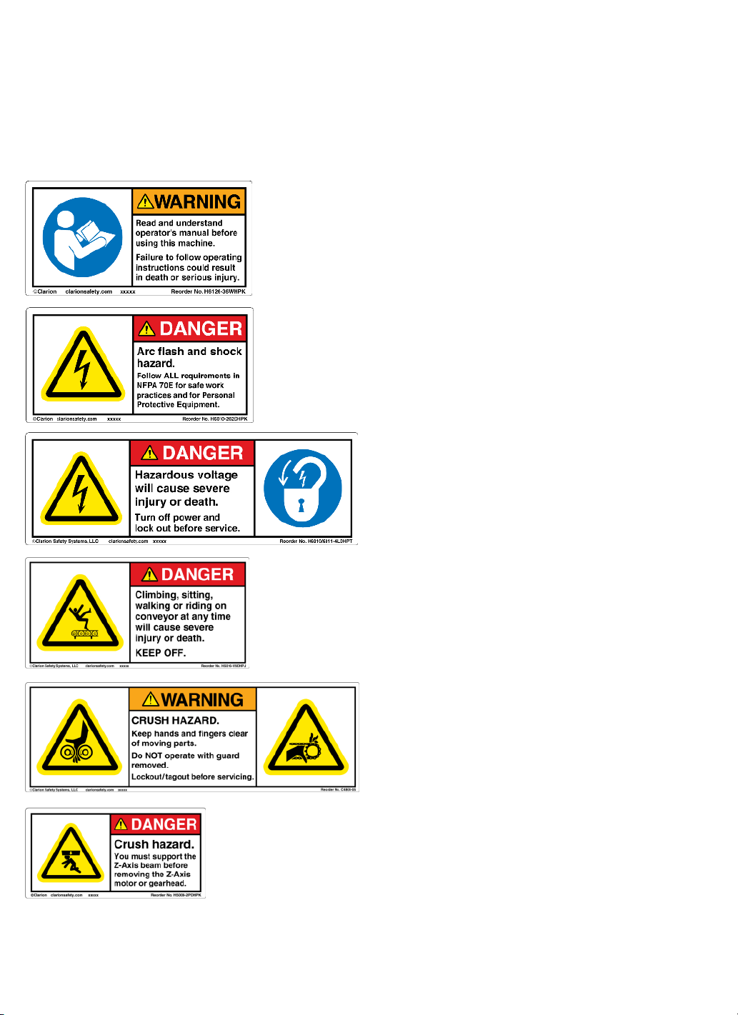
Safety Labels
In an effort to reduce the risk of injury to personnel working around the Wulftec / MJ
Maillis equipment, safety labels are placed at various points to alert them of potential
hazards. Please check equipment and note all safety labels. Make sure your personnel are
vigilant and obey these warnings. Shown below are typical labels that are attached to the
equipment.
PLACED ON ALL MOVING PLATEN, NEAR DRIVE.
PLACED ON ALL CONTROL PANELS.
PLACED ON ALL CONTROL PANELS.
PLACED ON AUTOMATIC MACHINE CONTROL PANELS.
PLACED ON ALL CONVEYORS.
PLACED ON ALL POWERED CONVEYORS, NEAR DRIVE.
Wulftec / M.J. Maillis Group
Page 5 of 36
Version 1.1.1 /May 2013
Page 6
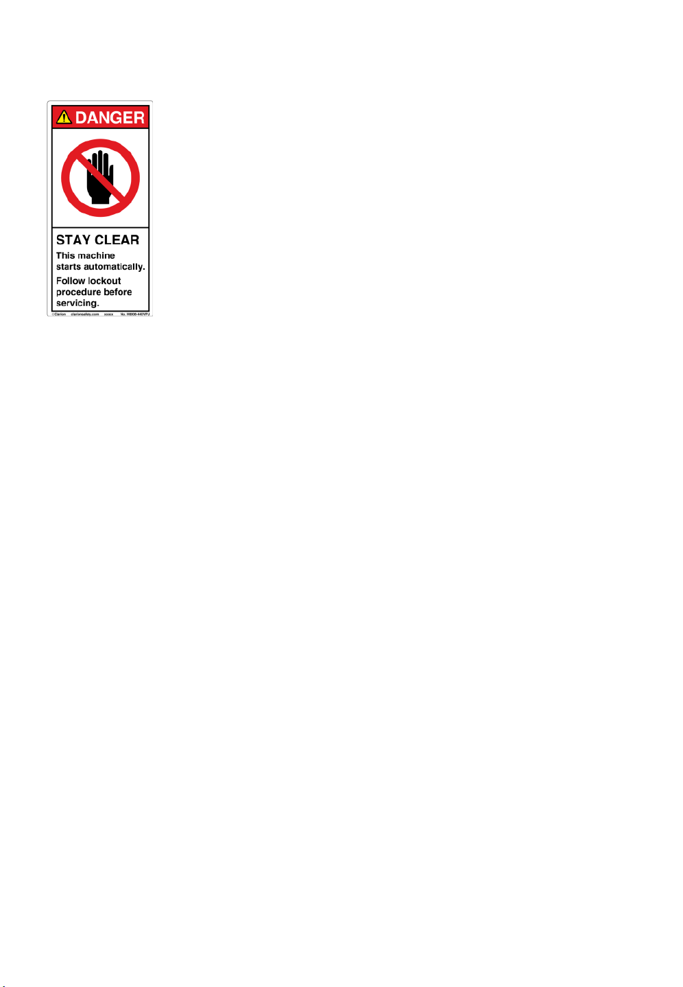
Safety Labels (cont’d)
NOTE: SPANISH, FRENCH AND PORTUGESE LABELS ARE AVAILABLE UPON REQUEST.
PLACED ON ALL MACHINE LEGS & TOWER
Wulftec / M.J. Maillis Group
Page 6 of 36
Version 1.1.1 /May 2013
Page 7
Safety
Read Carefully Before Operating
Any Wulftec Machinery
Wulftec stretch wrap machinery should be handled with the same caution and care as with any
other industrial equipment. Many automatic functions may be potentially hazardous. For this
reason, except for the authorized operator(s) and maintenance crew, other personnel should keep
clear at all times. It is especially important to be aware that mechanical or electrical components
may suddenly become active when the electrical panel is turned on.
Unstable loads being wrapped at high speeds are liable to fly apart and cause machine damage or
personal injury. For this reason, it is suggested that whenever attempting to wrap a "new" load
configuration, all personnel should be well clear of the wrapping area. The load should not be
wrapped at a higher speed than the machine was designed to handle (rotation speed: 17 RPM).
Always assume the machine is in an active mode. Disconnect control power prior to servicing,
adjusting or performing routine maintenance procedures.
WARNING!
Unless specifically stated, preceding all instructions in this manual, it must be well
understood that all inspection, maintenance, and repair should be performed only
when the electrical power is disconnected from the machine.
Please use extreme caution if it should become necessary to inspect, diagnose, or adjust the machine
while it is in operation. Only qualified individuals thoroughly familiar with the particular machine
should perform regular maintenance or inspections.
WARNING! Disconnect machine power supply before loading film.
Wulftec / M.J. Maillis Group
Page 7 of 36
Version 1.1.1 /May 2013
Page 8
D
Inspection and Installation
Upon Arrival, visually inspect machine for damage caused in transport. If damage to the machine
has occurred, it must be reported to the freight carrier immediately and Wulftec notified. As stated
in warranty on page 5, Wulftec is not responsible for damage caused in transit. If no damage is
apparent, carefully remove all wrapping material, strapping, blocks, etc.
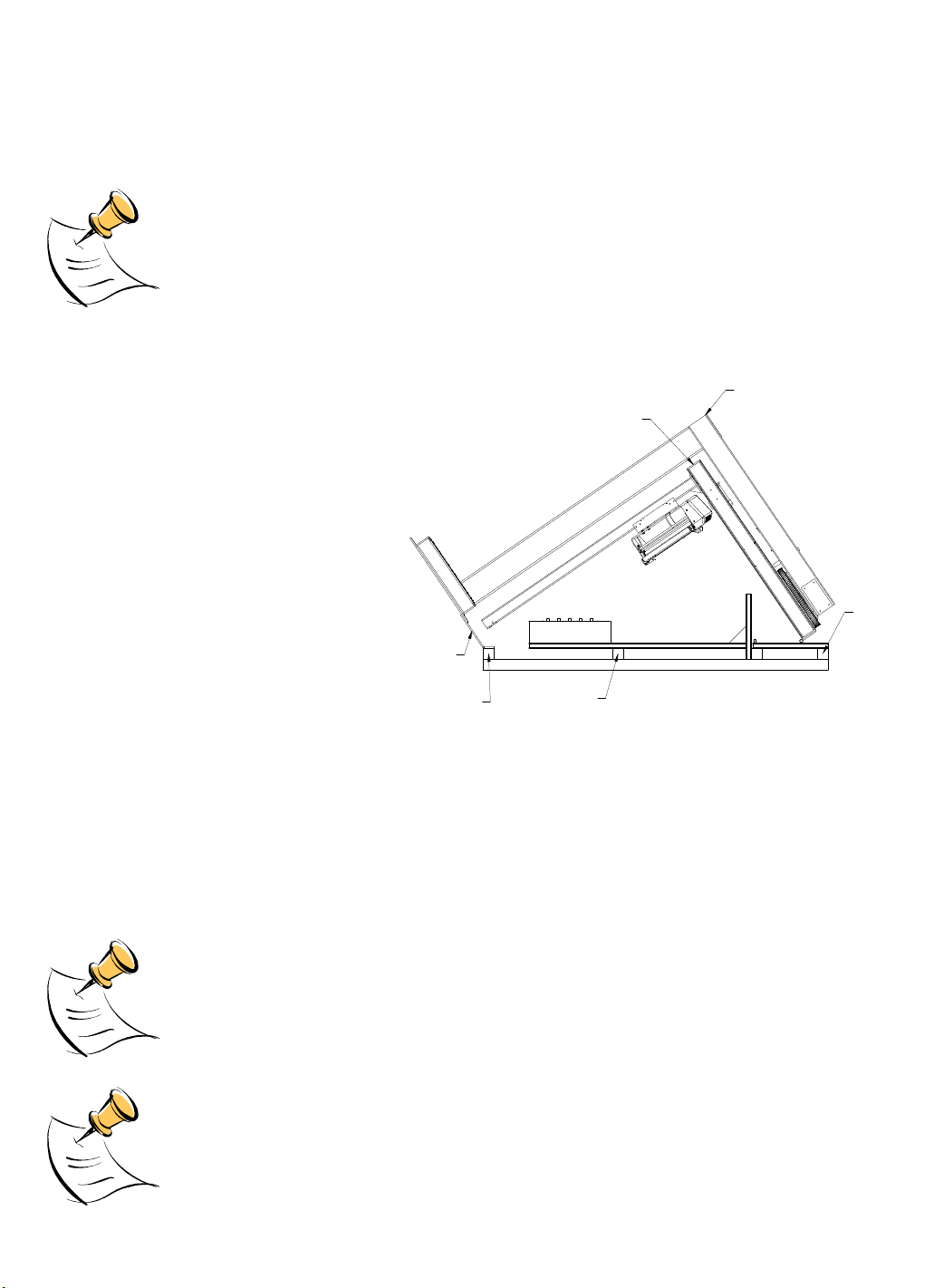
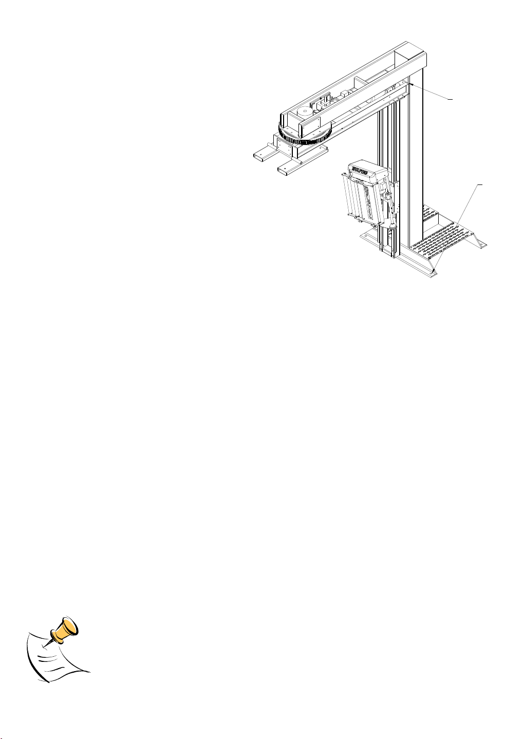
NOTE: Wulftec WRT Wrap Machines series are to be lifted for placement only by
the lifting tubes with an overhead crane, pulley blocks or forklift of at least twentyfive hundred (2,500) pounds lifting capacity
Lifting points identification
A. Lift here with overhead crane to remove skid.
B. Shipping bracket.
C. Bottom brackets
D. Cross member
E. Lag bolts.
F. Lift here with forklift.
B
A
Figure 1 Installation of a WRTA 150
Unpacking procedure
1. Remove lag bolts holding skid together. (10 pieces)
2. Leave cross member attached to machine. (1 piece) and lift machine from side with strap as
shown to remove skid, then set machine down on floor.
3. Insert forks as far as possible into lifting tubes. (See forklift requirement above).
4. Lift machine while moving forward until machine is in vertical position.
5. Lift machine above floor and remove bottom brackets.
6. Move machine to desired location and anchor to floor.
7. Unwrap carriage and install safety bumper and photoeye bracket.
8. Remove shipping bracket.
NOTE: Because of machine configuration, in various circumstances, some of the
elements of the machine may need to be disconnected. Please follow
instructions/indications on elements and/or relevant diagrams to reconnect.
C
E
NOTE: Wulftec recommends using 10 heavy-duty expansion shields of ¾”
diameter thread size with a minimum length of 4” as a minimum anchor in
concrete. The clamp needs to be anchored with 2 anchor nuts of ½” diameter.
F
Wulftec / M.J. Maillis Group
Page 8 of 36
Version 1.1.1 /May 2013
Page 9
Inspection and installation (cont’d)
Lifting points identification
A. Remove transportation plate that is found
here.
B. Anchoring holes.
1-Mechanical anchors: KB ¾” Ø from Hilti,
4” minimum engagement into concrete.
2-Chemical anchors: threaded rod ¾” Ø, Gr:
2, Epcon system, 3 ½” minimum
engagement into concrete.
Verification of the structural capacity of the
floor to be done by others
Figure 2 Anchoring points for a WRTA 150
A
B
Note: The type of anchors for the Control Panel and Clamp (if applicable) is to the customer’s
discretion.
This machine needs to be connected to a dedicated line. A dedicated line is a line that is powered
from one breaker or fuse, and that has no other device connected to it. Furthermore, the line shall
be such that the voltage at the outlet will not drop more than 5% under full load. Use of extension
cords is not recommended.
To measure the voltage drop, measure the voltage at the outlet with nothing connected to it this is
VA, then measure the lowest voltage during machine operation. Please read during the complete
cycle and note the lowest value, this is VB.
Take the difference between VA and VB and divide it by VA. This will give you the voltage drop
percentage. Drop= (VA-VB)/VA. This drop should remain under 5% for proper machine operation,
and for compliance with the electrical code.
As an example, an outlet connected to a 15A breaker, wired with #14AWG wire, should not be
further than 70' from the breaker, to meet the 5% voltage drop.
NOTE: Because of machine configuration, in various circumstances, some of the
elements of the machine may need to be disconnected. Please follow
instructions/indications on elements and/or relevant diagrams to reconnect.
Wulftec / M.J. Maillis Group
Page 9 of 36
Version 1.1.1 /May 2013
Page 10
Inspection and installation (cont’d)
1
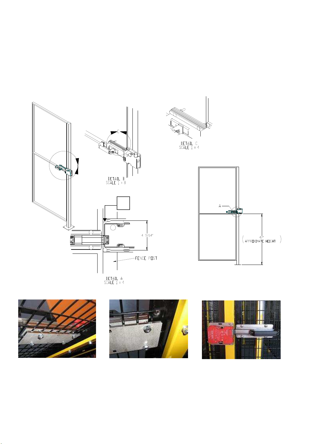
Installation of Fence Handle
See the following drawings in order to facilitate the installation of the handle on the safety fencing.
Refer to assembly drawing 6MFEN00496.
1: Clamp key switch plate in place with edge, flush with post. Transfer holes approximately center of
slot for adjustment. Drill 9/32” hole through post. Install key switch with carriage bolts.
Align slide bolt with key switch. Shims must pinch door panel angle iron. Tighten nuts.
Wulftec / M.J. Maillis Group
Page 10 of 36
Version 1.1.1 /May 2013
0MINS00006, rev. 1
Page 11
Film Loading and Threading
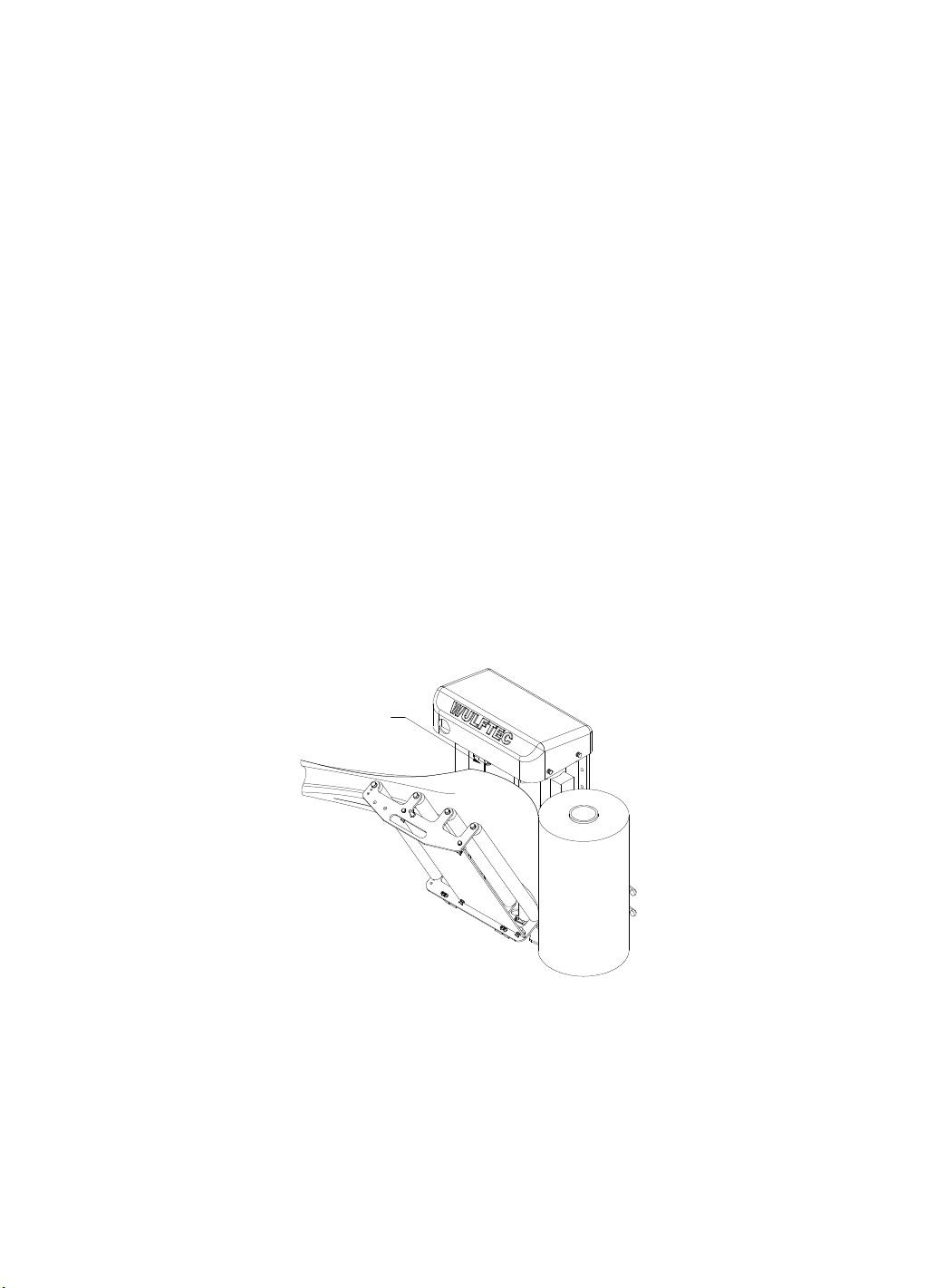
The film roll should be loaded so that the tacky surface will face inward on the pallet load.
1. *Make sure the machine is in stop mode before opening the fencing door. Do not press on E-stop.
2. *Open safety fencing door (if applicable).
3. Push the lock on the carriage gate latch to unlock carriage door.
4. Remove empty film roll.
5. Ensure that the inner core of the new film roll is undamaged. If the lower (bottom) of the inner
core is damaged or somewhat unwound, trim or shave it with a sharp knife.
6. Lift the film roll and make it slide along the film support roll. Then move the bottom of the film
roll over the bottom cone film roll holder to ensure that the roll is securely in place.
7. Pull the film from the roll until a good film web is reached, cut the film and discard the damaged
portion.
8. Pull out the film manually; ensure enough length to reach the clamp when it’s closed.
9. Place film loosely between door and pre-stretch rollers, then close the door and ensure that the
carriage locks are correctly locked (this is a 2-position lock; make sure to reach the 2
when closing the door).
10. Pull out the film manually in order to verify proper loading and operation of the film carriage.
11. Cut off the excess film and place the film on the clamp, then close the clamp with the clamp jog
push button (located on the wipe plate near the e-stop).
12. Close the door, press reset to rearm the door circuit then acknowledge the alarm and restart the
machine.
13. If film breaks during a wrap cycle, repeat steps 7 to 12 or attach film to the product.
nd
position
Carriage Lock
Figure 3 Film loading and threading
Wulftec / M.J. Maillis Group
Page 11 of 36
Version 1.1.1 /May 2013
Page 12
Film loading and threading (cont’d)
WARNING! Before threading the film, press on the dancer bar once door is
opened to make sure the pre-stretch rollers are not turning. If they are, contact a
Wulftec Customer Service representative immediately. Do not touch the carriage.
Inadvertent movement of the dancer bar will cause the rollers to turn abruptly,
creating the possibility of serious injury. The operator must respect the film
loading and threading instructions AT ALL TIMES!
NOTE: If the film web breaks during the cycle, reattach the film, or if necessary,
rethread the film following the instructions. It is not necessary to reset the
machine. If E-stop is activated, the pre-stretch and the clamp will not work. If the
E-Stop is pressed, pull it.
The machines equipped with a standard carriage are programmed to stop when a
lack of film occurs. In a wrap cycle during which the rotation speed is higher
than 10Hz and the pre-stretch motor stops working for more than three (3)
seconds, the machine will fall into a stop state. The cause is either a stop a lack
of film or a film break. Follow the film threading procedure (previous pages) to
rethread the film to start/restart a cycle.
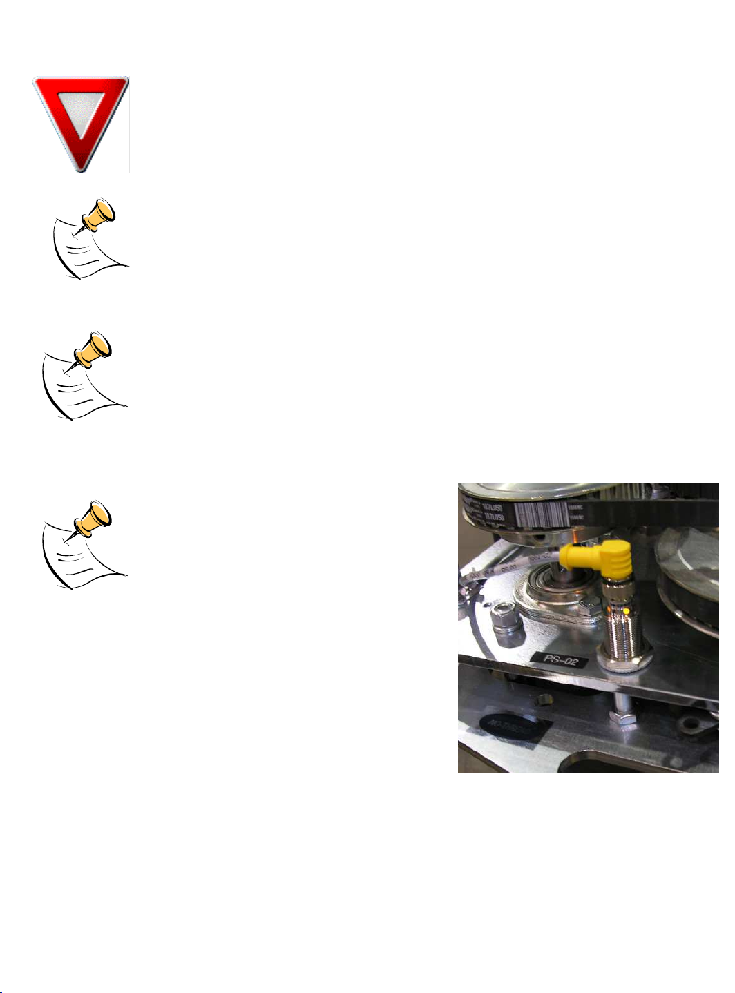
The machines are equipped with a proximity
sensor used to determine if the carriage door
is closed properly. This sensor can be seen
through the hole in the carriage cover. When
the light is lit, it indicates that the carriage
door is closed properly. If the door is open,
the pre-stretch motor will stop working or if
the machine is running a wrapping cycle, it
will stop by itself rapidly. If the light is not lit, make sure the
door is properly closed. The machine is ready for a start cycle.
Wulftec / M.J. Maillis Group
Page 12 of 36
Version 1.1.1 /May 2013
Page 13

Wrapper Controls
Controls
Power on/off Turns power OFF/ON to the machine.
Reset Brings the carriage down and moves the rotary arm
Functions
back to home position.
Carriage
Up/Down
Reinforce wrap Reinforce wrap function allows the operator to reinforce
Manual rotation Manual rotation moves the rotary arm to desired
Start/stop Starts or stops the wrap cycle (also continues the wrap
Emergency stop Temporarily stops the sequence by cutting all power to
Note: If inverted controls option has been chosen, you will keep the same controls although the
control cabinet has a different appearance.
Note: An amber safety flashing light is installed on top of the enclosure. The light flashes during
machine operation.
With the machine cycle stopped, allows carriage to be
moved up or down.
any section of the load by pausing the carriage
movement while the rotary arm continues. The
number of turns in reinforce wrap is determined by the
amount of time the switch is activated. This function
allows the operator to set a number of reinforce wraps
in a minimal amount of time.
position.
cycle after the top cover pauses or after stopping "in
cycle" by using the emergency stop) and brings the
carriage down in spiral up mode.
the drives. Wrapping sequence may be re-started after
pressing E-stop. (To re-start the wrap cycle, simply
release the E-stop and press the START/STOP button.)
Wulftec / M.J. Maillis Group
Page 13 of 36
Version 1.1.1 /May 2013
Page 14
Wrapper Controls (Cont’d)
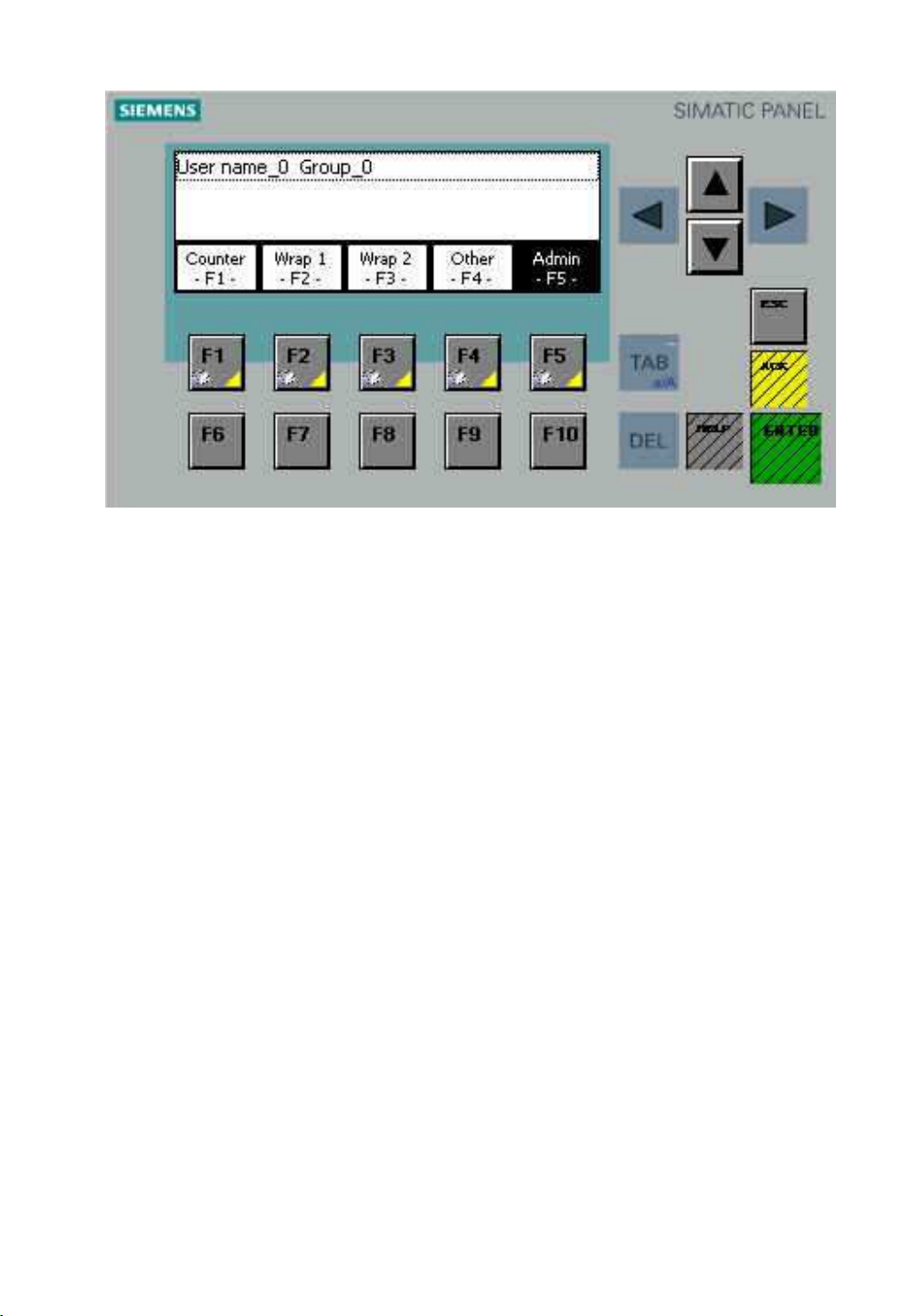
This page is used to change passwords
Wulftec / M.J. Maillis Group
Page 14 of 36
Version 1.1.1 /May 2013
Page 15
Wrapper Controls (Cont’d)
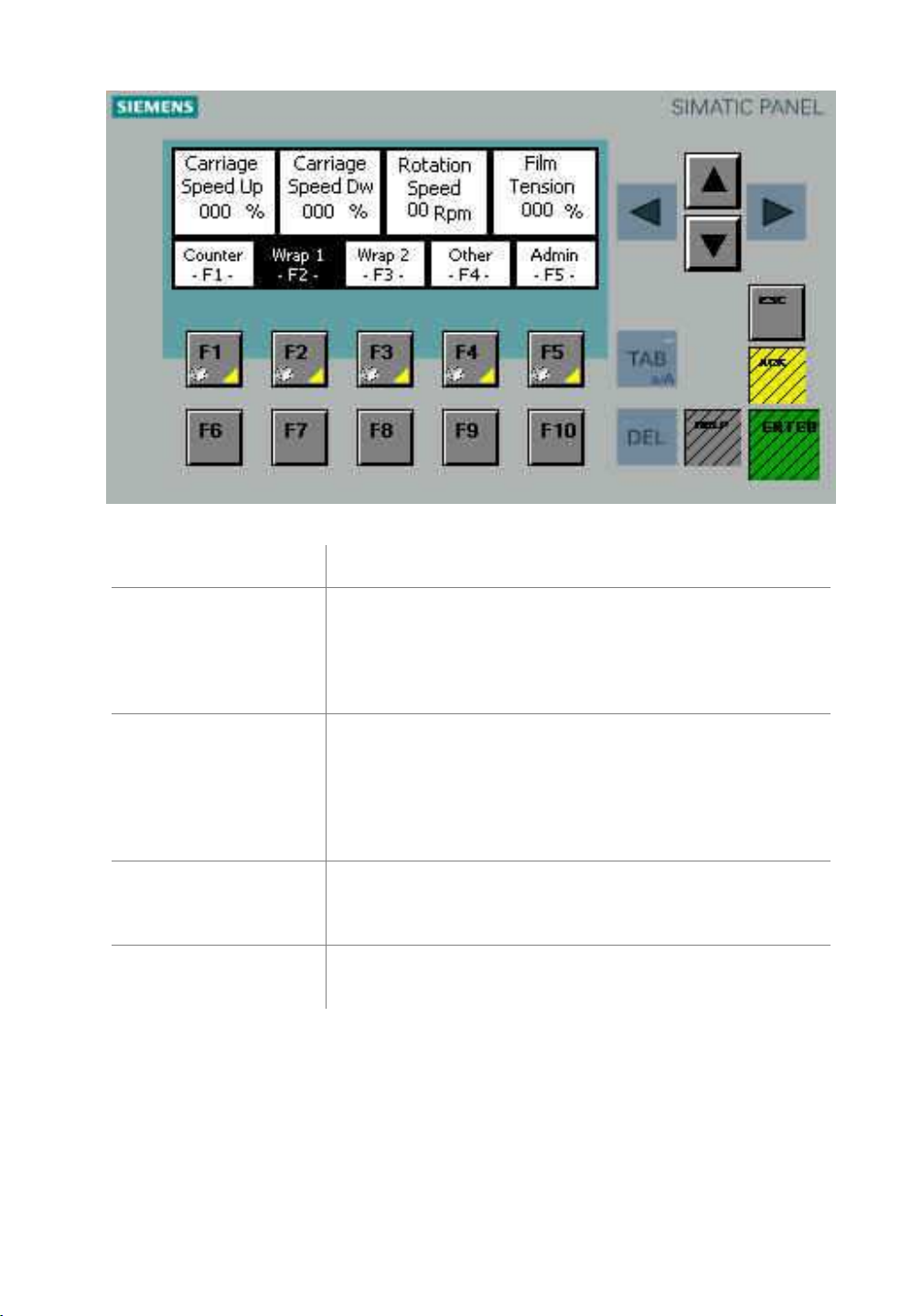
Controls
Carriage speed up Controls speed of carriage in up direction, which has
effect on cycle time and film overlap. It should be
adjusted with great care when trying to optimize speed
while maintaining quality wrap on product. Min. on
potentiometer is lowest speed attained.
Carriage speed down Controls speed of film carriage in the downward
direction, which has an effect on cycle time and film
overlap. It should be adjusted with great care when
trying to optimize speed while maintaining quality wrap
on product. Min. on potentiometer is lowest speed
attained.
Rotation speed Allows the rotation to be set at the speed best suited to
the load, variable from min. (being the lowest speed
attainable without stopping) to 17 RPM.
Film tension Controls the tension between film carriage and pallet
load (i.e. higher % tension = tighter wrap).
Functions
Wulftec / M.J. Maillis Group
Page 15 of 36
Version 1.1.1 /May 2013
Page 16
Wrapper Controls (Cont’d)
Controls
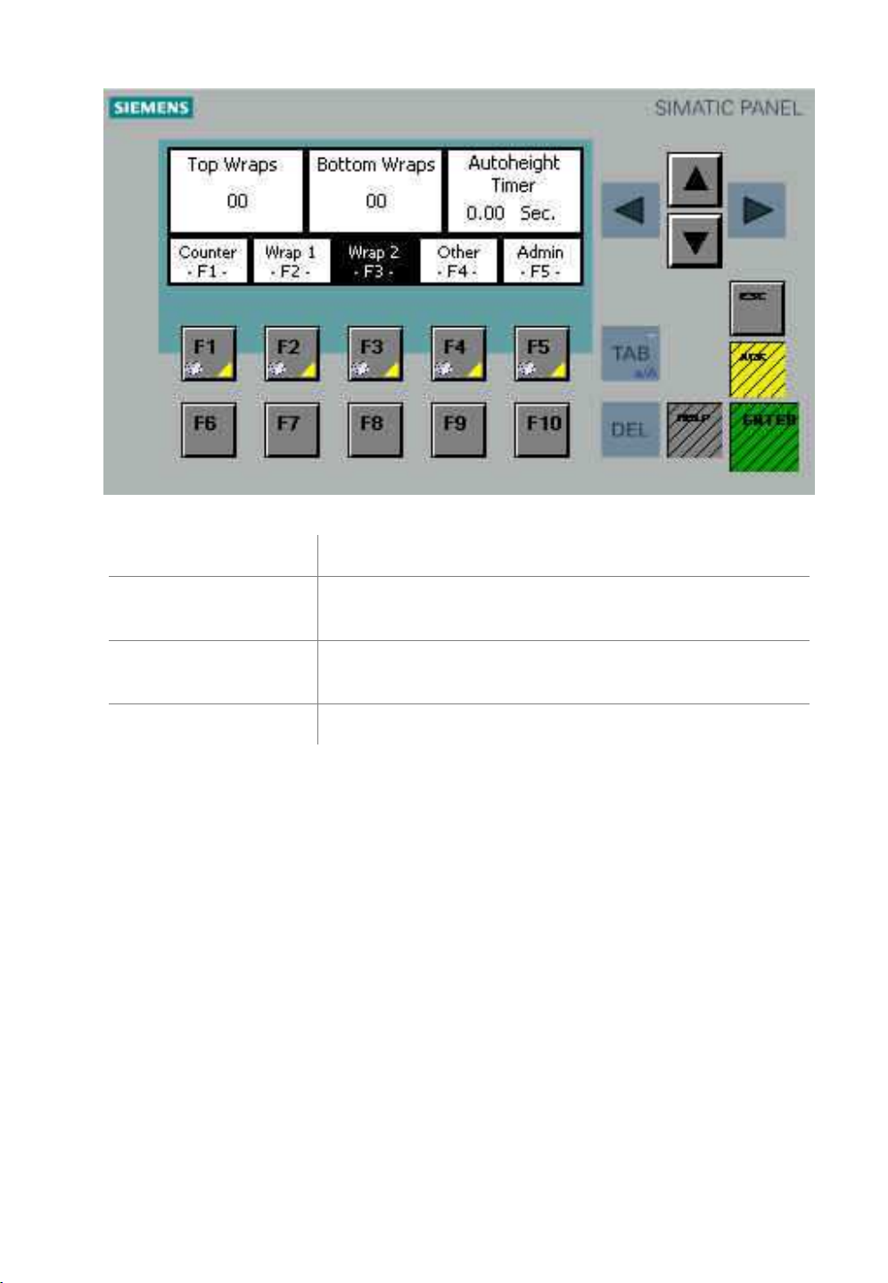
Top wraps Determines the number of wrap layers at the top of the
load, adjustable from 0 to 10.
Bottom wraps Determines the number of wrap layers at the bottom of
the load, adjustable from 0 to 10.
Autoheight Timer Used to set the timer for the overwrap.
Functions
Wulftec / M.J. Maillis Group
Page 16 of 36
Version 1.1.1 /May 2013
Page 17
Wrapper Controls (Cont’d)
Controls
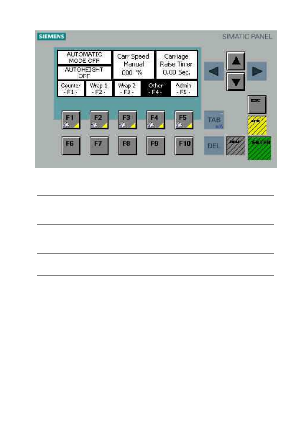
Automatic Mode
On/Off
Autoheight off/on Allows "autoheight sensing" for pallet load height
Carriage Speed
Manual
Carriage Raise Timer Used to set the time during which the carriage will
Used to select the machine automatic or semiautomatic mode. In automated mode, the clamp and
cut arm will be activated.
variations. (There are limit switches on the carriage
with adjustable stops on tower as safety override).
Used to set the carriage speed (%) when machine is set
to manual mode.
move up at the beginning to clear the clamp.
Functions
Wulftec / M.J. Maillis Group
Page 17 of 36
Version 1.1.1 /May 2013
Page 18
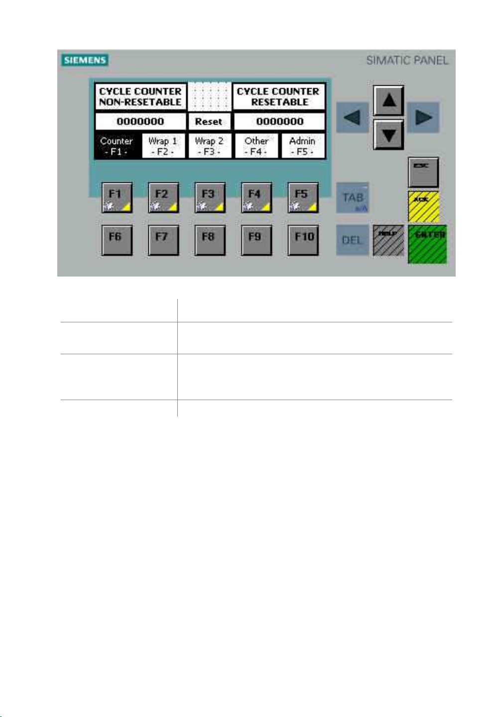
Wrapper Controls (Cont’d)
Controls
Cycle Counter Counts the amount of wrapping cycles since the
machine was first started.
(Resettable) Cycle
Counter
Reset Press Reset button to reset the resettable cycle counter.
Counts the amount of wrapping cycles since the last
reset. To reset this counter, you will need to enter the
password.
Functions
Wulftec / M.J. Maillis Group
Page 18 of 36
Version 1.1.1 /May 2013
Page 19

Mode of Operation – Standard System
1. Load film and then put power on.
2. On the touch screen, go to the automatic page.
3. Select Wrapping Off if wrapping not required.
4. Depress "Reset".
5. When reset completed, depress "Start". *The button will light up.
6. Machine waits for a load.
Beginning of the Wrap Sequence
NOTE: You can temporarily stop the wrapping sequence at any time. This can be
done by pressing the Start or E-Stop button. (To re-start the wrap cycle, simply
release the E-Stop and press Start). It is to be noted that by resetting the machine,
a new cycle is initiated.
7. Place the load in the center of the wrapping zone.
8. Activate the pull cord or start/stop button to begin rotation.
9. After 1.5 turns, the clamp releases the film.
10. The carriage moves up.
11. The top of the load is sensed.
12. The machine completes the top wraps.
13. The carriage moves down.
14. The carriage stops at bottom limit switch.
15. The machine completes the bottom wraps.
16. The rotation slows to minimum speed.
17. The rotation stops at home position.
18. The film push arm goes out.
19. The clamp closes.
20. The cutter wire rotates into film and cuts it on contact.
21. The film is wiped.
22. The film push & wipe arm goes back to home position.
End of Wrap Sequence
To activate Manual mode, go to the manual page on the touch screen. By doing so, automatic
sequence and reset are immediately interrupted.
Wulftec / M.J. Maillis Group
Page 19 of 36
Version 1.1.1 /May 2013
Page 20

Cut Arm Operation
1. During the last ½ turn, the rotation slows down.
2. When the boom reaches its home position, the cut arm is activated.
3. During its activation, the cut wire heats up and cuts the film web.
4. When the arm reaches the second proximity sensor, the motor is “reversed” and the arm returns
to its home position.
5. It stops when it reaches the back proximity sensor.
6. Machine is now ready for another cycle.
Wrapping the Load
1. Turn the power switch to "On" (the power on light should be illuminated).
2. Place a load under the arm.
3. Pull the end of the film from the carriage and stick it on the pallet or on the load.
4. Be sure that all pallet jacks, forklifts and personnel are clear of the wrapping area.
5. Select the required wrapper controls.
6. Depress the "Start" button to initiate the wrap cycle.
7. When the wrap cycle has been completed, press the cut film web onto the load or tuck it at the
end under the lower film wrap, if required.
8. The load may now be removed and the machine is ready for the next cycle.
Wulftec / M.J. Maillis Group
Page 20 of 36
Version 1.1.1 /May 2013
Page 21
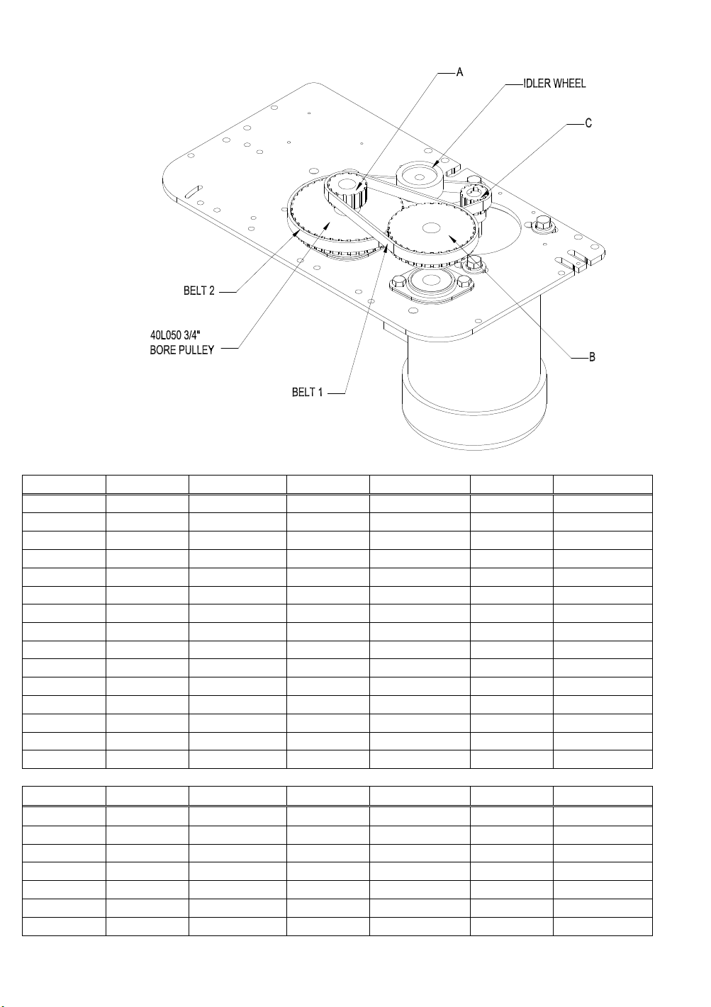
Optional Pre-stretch Ratios – Belt Driven
RATIO % "A" WULFTEC "B" WULFTEC BELT "1" WULFTEC
0 16 0MSPK00131 12 0MSPK00168 150L050 0MCHN00044
30 14 0MSPK00130 14 0MSPK00130 150L050 0MCHN00044
40 13 0MSPK00132 14 0MSPK00130 150L050 0MCHN00044
50 13 0MSPK00132 15 0MSPK00124 150L050 0MCHN00044
75 12 0MSPK00168 16 0MSPK00131 150L050 0MCHN00044
100 14 0MSPK00130 21 0MSPK00134 165L050 0MCHN00045
125 17 0MSPK00125 28 0MSPK00175 187L050 0MCHN00046
150 16 0MSPK00131 30 0MSPK00128 187L050 0MCHN00046
175 21 0MSPK00134 44 0MSPK00138 225L050 0MCHN00047
185 15 0MSPK00124 32 0MSPK00129 187L050 0MCHN00046
200 14 0MSPK00130 32 0MSPK00129 187L050 0MCHN00046
225 13 0MSPK00132 32 0MSPK00129 187L050 0MCHN00046
250 12 0MSPK00168 32 0MSPK00129 187L050 0MCHN00046
275 14 0MSPK00130 40 0MSPK00170 210L050 0MCHN00057
300 13 0MSPK00132 40 0MSPK00170 202L050 0MCHN00065
RPM “C” WULFTEC BELT "2" WULFTEC "D" WULFTEC
12 12FL050 0MSPK00133 210L050 0MCHN00057 40L050 0MSPK00170
15 12FL050 0MSPK00133 210L050 0MCHN00057 40L050 0MSPK00170
17 12FL050 0MSPK00133 210L050 0MCHN00057 40L050 0MSPK00170
21 14FL050 0MSPK00169 210L050 0MCHN00057 40L050 0MSPK00170
24 14FL050 0MSPK00169 210L050 0MCHN00057 40L050 0MSPK00170
30 16FL050 0MSPK00192 225L050 0MCHN00047 40L050 0MSPK00170
43 16FL050 0MSPK00192 202L050 0MCHN00065 36L050 0MSPK00226
*All “C” pulleys are 5/8” bore
Wulftec / M.J. Maillis Group
Page 21 of 36
Version 1.1.1 /May 2013
Page 22

Setting Wrap Parameters
The operator can select or tune a number of variable wrapping parameters in order to achieve the
desired wrap configuration. These controls also affect the cycle time.
Film Carriage / Rotation Speed
The film carriage speed control varies the rate at which the carriage travels up and down. This, in
conjunction with the rotation speed, determines the amount of film overlap. The slower the carriage
speed, given the fact that the rotation speed remains unchanged, the greater the overlap. The
rotation speed should be set to optimum speed for a given load stability to achieve optimum cycle
times.
Upper/Lower Limit Settings
The upper limit stop bracket sets the upper limit of the wrap. If this bracket is set lower than the top
of the load, it will override the photoeye (standard on most machines). The lower limit stop bracket
located on the arm sets the lower limit of the wrap.
Top Wraps
The number of top wraps applied to the top of the load has to be set on the touch screen. It can be
set to apply zero (0) to nine (9) wraps to the top of the load.
Bottom Wraps
The number of bottom wraps applied to the bottom of the load has to be set on the touch screen. It
can be set to apply zero (0) to nine (9) wraps to the bottom of the load.
Overwrap
The film overwrap is the extent to which the film carriage wraps above the load. Under stretch, the
film tends to fold itself over the top, providing a greater degree of retention. The overwrap can be set
by adjusting the timer on the touch screen. The upper limit stop may also be used to set the
overwrap (if this limit switch is activated before the photoeye, it will override it). Note that the
carriage speed up setting is going to change the overwrap adjustments.
Film Tension (Post Stretch)
The film tension control on the control panel inside the enclosure adjusts the tension (or pull)
between the film carriage and the load. The higher the tension control is set, the tighter the load is
wrapped.
NOTE: For proper performance of the film carriage, the dancer bar should float
between its limits. Avoid setting the tension so high that the dancer roller becomes
pinned against the secondary roller. If additional tension is desired, simply turn the
adjustment knob to apply more pressure upon the dancer bar.
Wulftec / M.J. Maillis Group
Page 22 of 36
Version 1.1.1 /May 2013
Page 23
Setting Wrap Parameters (Cont’d)
Photoeye Settings
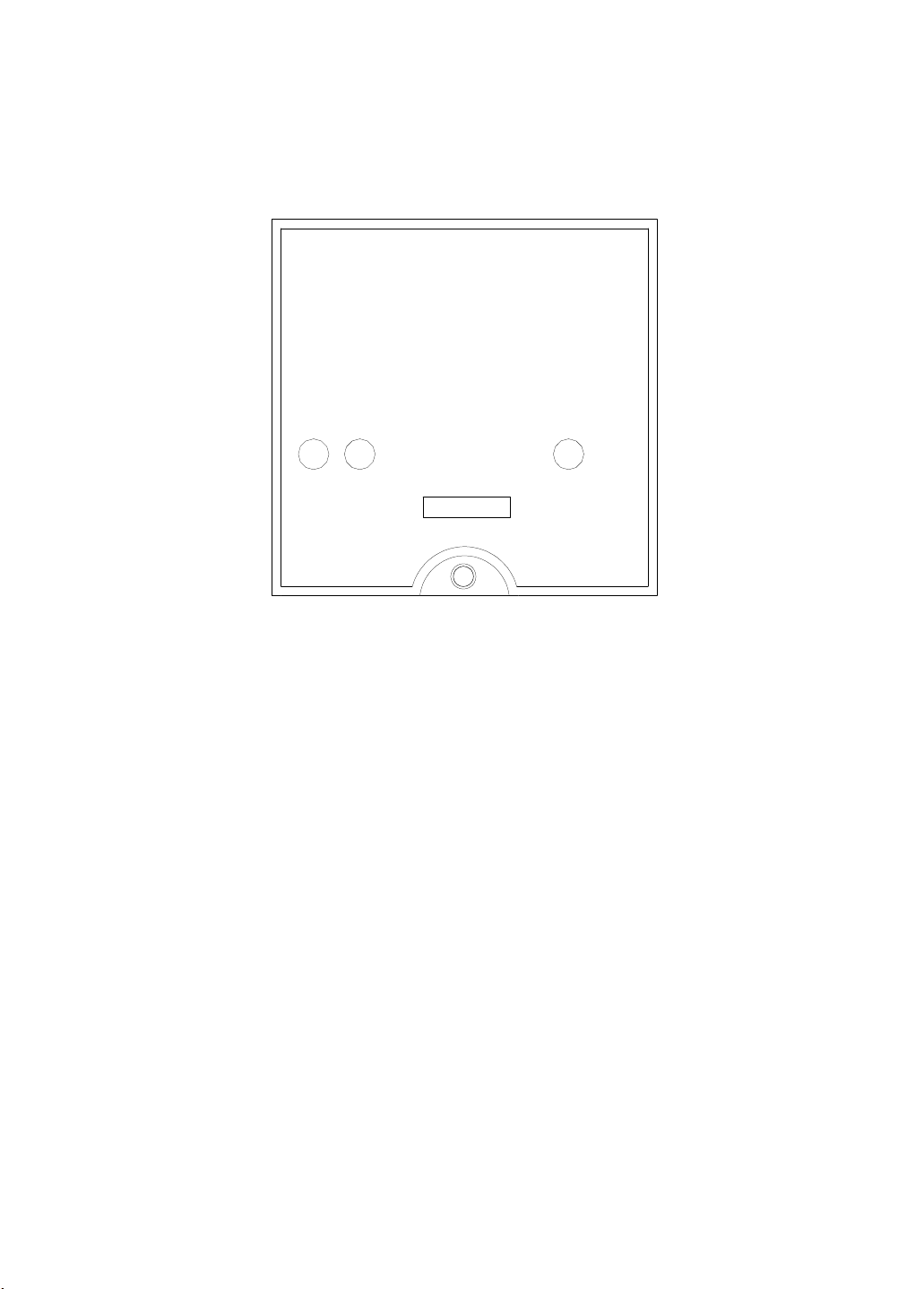
Figure 4 Retroflective Photoeye
t
l
u
a
p
n
t
g
u
i
O
S
Light Dark
Operate
r
e
w
o
P
LED Indicators
Each sensor features three LED indicators to help you program and use the sensor.
Green
The green LED indicates “power”. When this indicator is lit, power is on.
Amber (Yellow)
The amber or yellow LED indicates “output.” This indicator will light up when an output is present.
In AC versions, this indicator shows that the relay is closed. In DC versions, this indicator shows
that the transistor is switched according to the light/dark switching that has been set.
Red
The red LED indicates “signal strength.” This indicator is solid when the signal is good; it flashes
when the signal is marginal. This indicator is especially helpful for use in alignment or to determine
whether dirt and dust build-up will interfere in operation. A flashing signal strength indicator will
trigger the alarm output.
Light/Dark Switching
Light and dark switching can be toggled using the switch below and between the red signal strength
and green power LEDs. Simply move the switch toward “light” for light switching or “dark” for dark
switching.
Sensitivity Adjustment
Using a small screwdriver, turn the sensitivity adjustment, located to the right of the green power
LED. To increase sensitivity, turn clockwise; to decrease sensitivity, turn counter-clockwise.
However, it is strongly recommended that this switch always be switched to “dark”.
Wulftec / M.J. Maillis Group
Page 23 of 36
Version 1.1.1 /May 2013
Page 24
Photoeye Settings (Cont’d)
DS-60 Photoeye Adjustment
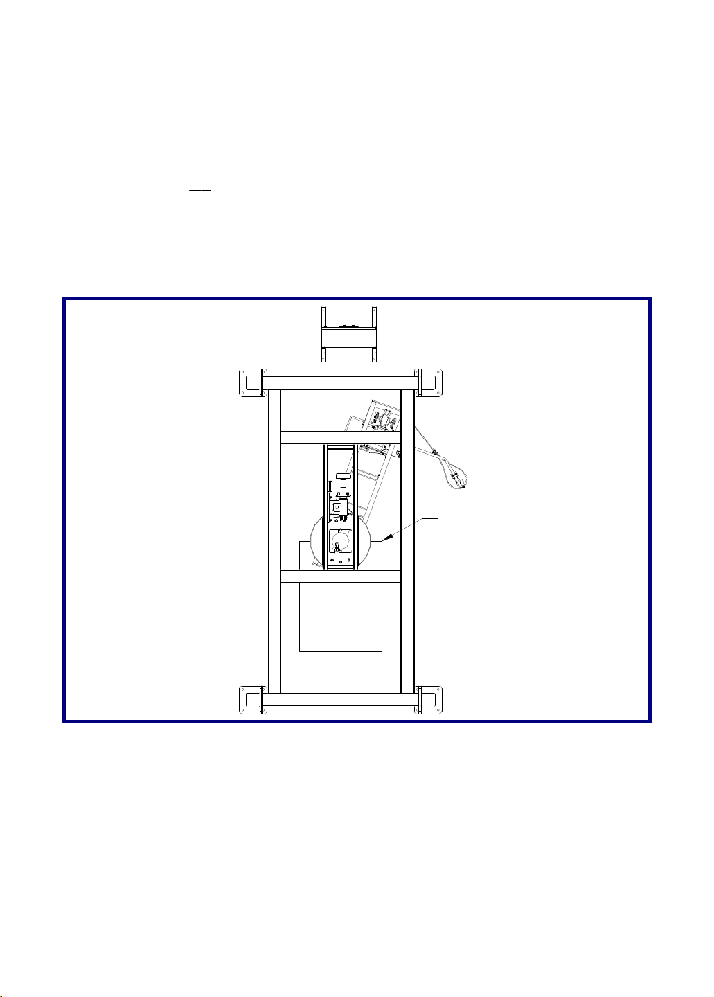
1. Using a forklift, place a load as indicated in the drawing. The load has to be the same as the ones
that are going to be wrapped with that machine.
2. Set the photoeye’s dial to the “ALIGN” position. When pressing down on the “TEACH” button you
will see a red spot where the DS-60 is aimed at. Be sure you aim it at the center of the load.
1Q
3. Turn the dial at the “
4. Turn the dial at the “
5. Turn the dial at the “RUN” position.
6. You can increase or decrease the amount of overwrap through the HMI.
” position and hold the teach button until the lights stop flashing.
2Q
” position and hold the teach button until the lights stop flashing.
Face of load at
center of rotation
Wulftec / M.J. Maillis Group
Page 24 of 36
Version 1.1.1 /May 2013
Page 25

Photoeye Settings (Cont’d)
Rotary Arm Bumper - Photoeye Function: This photoeye detects if the arm’s path is clear. If an
obstacle is in the way, the machine will create an alarm.
Autoheight Photoeye - Photoeye Function: This photoeye tells the carriage to stop at the right
height for the desired overwrap.
Wulftec / M.J. Maillis Group
Page 25 of 36
Version 1.1.1 /May 2013
Page 26

Setting Wrap Parameters (cont’d)
Photoeye Response Delay Time
Since most pallet loads are square or rectangular, as opposed to round, there must be a delay time
setting in order to remain "ON" as the arm turns around the load and reflects the diffuse photoeye's
signal away from its own receiver. The delay is set in the PLC program and can be changed via the
touch screen.
Automatic Height Sensing
All Wulftec automatic machines are equipped with a photoeye sensor, for load height sensing. This
allows for variations in load height, while maintaining the predetermined "overwrap" setting. All
machines are equipped with manual override (limit switches).
NOTE: When using a 30” carriage with a 20” film on the machine, the
autoheight photoeye will not work on small load higher than 20” and smaller
than 33”.
NOTE: The upper limit stop controls the overwrap of the pallet when the
photoeye mounted on the carriage is not in use.
Setting the Limit Stop
Lower:
Loosen the lower limit stop.
Slide stop block into desired position.
Tighten securely.
Upper:
Loosen the upper stop limit.
Slide the stop block into desired position.
Tighten securely.
NOTE: The bottom limit switch block should be adjusted according to the
downward speed of the carriage so that it does not over travel. At each end of the
limit stop adjustment rail are over travel security stops that are fixed in position.
Under no circumstances are these to be removed, as serious machine damage
and/or personal injury may result.
Wulftec / M.J. Maillis Group
Page 26 of 36
Version 1.1.1 /May 2013
Page 27
Setting Wrap Parameters (Cont’d)
Analog Sensor Adjustment
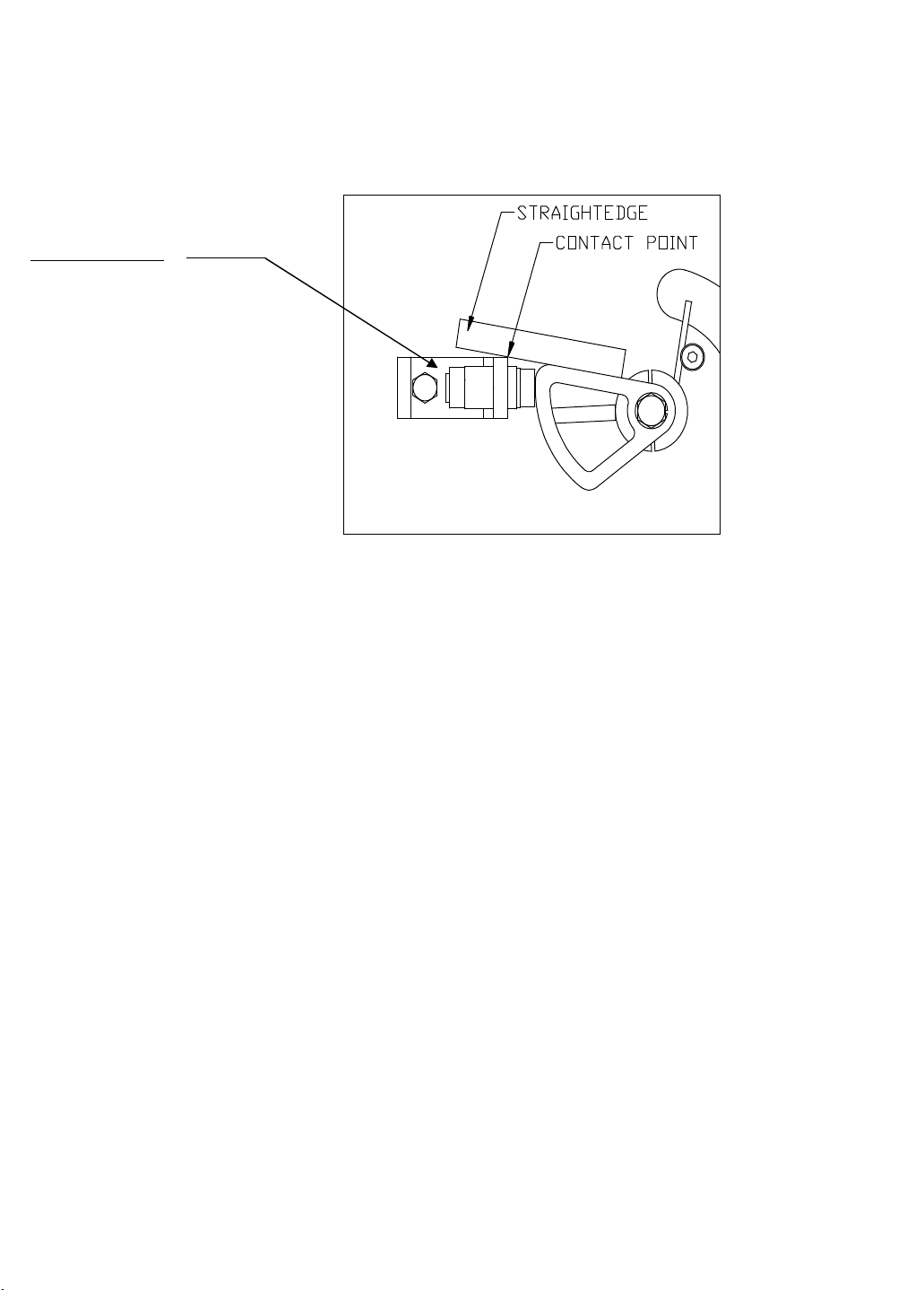
Follow these steps to replace or adjust the analog sensor and cam:
Light on Sensor
Constant = Reading
Flashing = Out of Range
Figure 5 Analog sensor adjustment
1. Activate the Emergency Stop.
2. Remove the film roll.
3. Remove the carriage cover.
4. Make sure that the dancer bar is completely retracted and at home position.
5. Using a ruler, align the right side of the cam with the edge of the analog sensor bracket. Tighten
the bolt to secure the cam in place.
6. Loosen the detector, lean it against cam. Then move back gradually until the light on the
detector stops flashing and becomes constant, and then tighten the detector in position.
7. Rearm the emergency stop circuit (Caution: the pre-stretch motor can restart).
8. For PowerFlex 4 : make sure that parameter A110 is at 20
PowerFlex 40: jump at step 10
9. Make sure that when the dancer bar is completely retracted with its initial position, the motor
does not turn, and when the dancer bar is moved gently, the motor starts gradually. If the motor
turns in initial position (too far from the cam), or it starts too far (too close from the cam), loosen
the nuts and readjust the analog sensor slightly.
10. Reinstall the carriage cover.
11. Install film roll.
Wulftec / M.J. Maillis Group
Page 27 of 36
Version 1.1.1 /May 2013
Page 28
Setting Wrap Parameters (cont’d)
Proximity Sensor
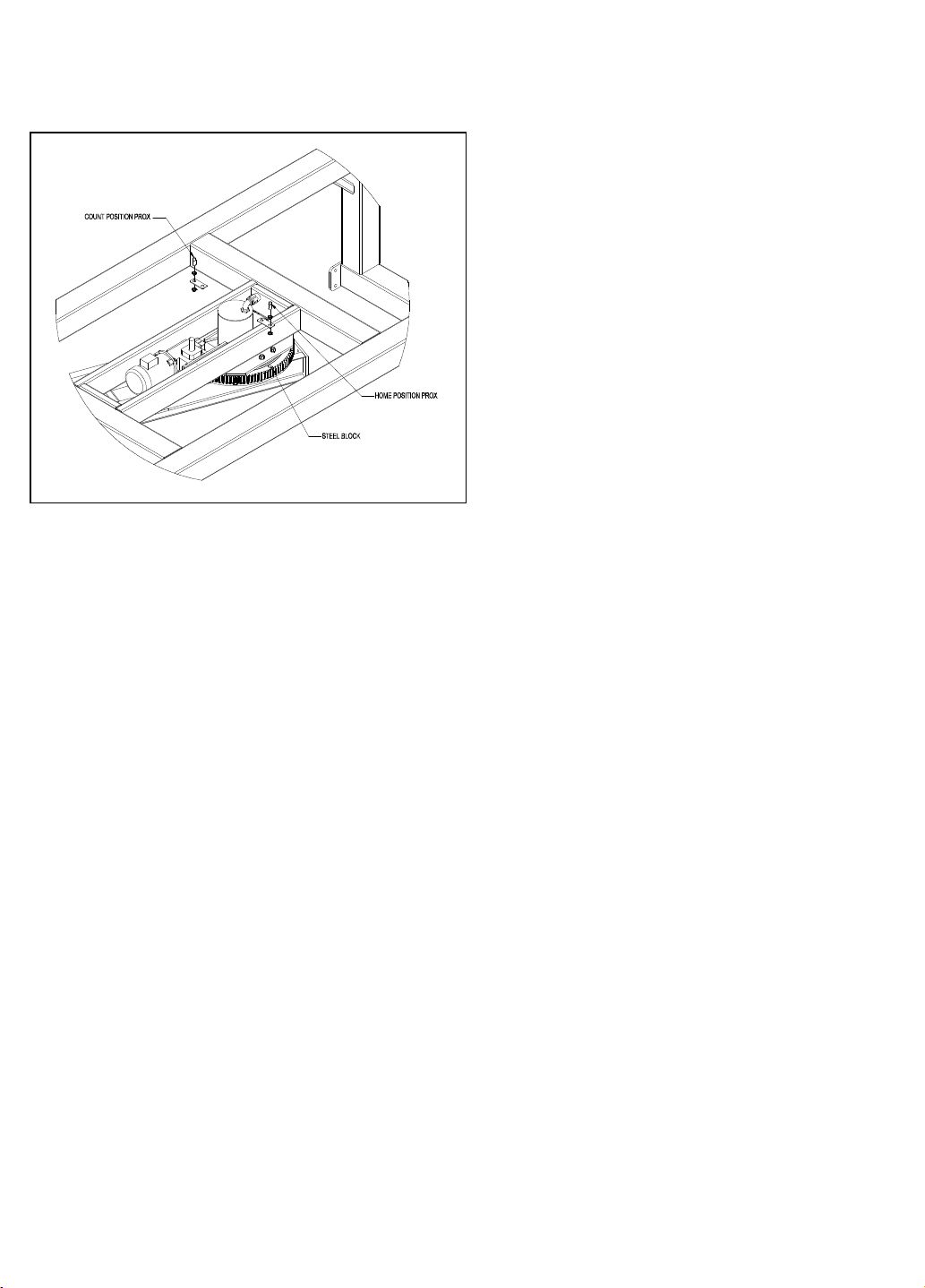
The first sensor is located beside the rotary arm
ring gear and is used to count the rotary arm
revolutions (to match the wrap counts selected
on the panel). The reading is obtained by a flat
piece of steel glued on the ring gear. The second
sensor is used to indicate home position to cut
film and also, because the WRT series uses two
(2) counts per rotary arm revolution, to give the
second count required.
Figure 6 Proximity Sensor
Revolution and Home Position Sensors
Wrappers from Wulftec use proximity sensor to count revolutions and to determine the arm’s home
position. These two (2) sensors can be found on the top of the ring gear and they are reading off a
piece of steel glued on the top of the ring gear.
Reed Switches Adjustment
These switches indicate the push arm’s initial and limit position. Red light at the end of the arm
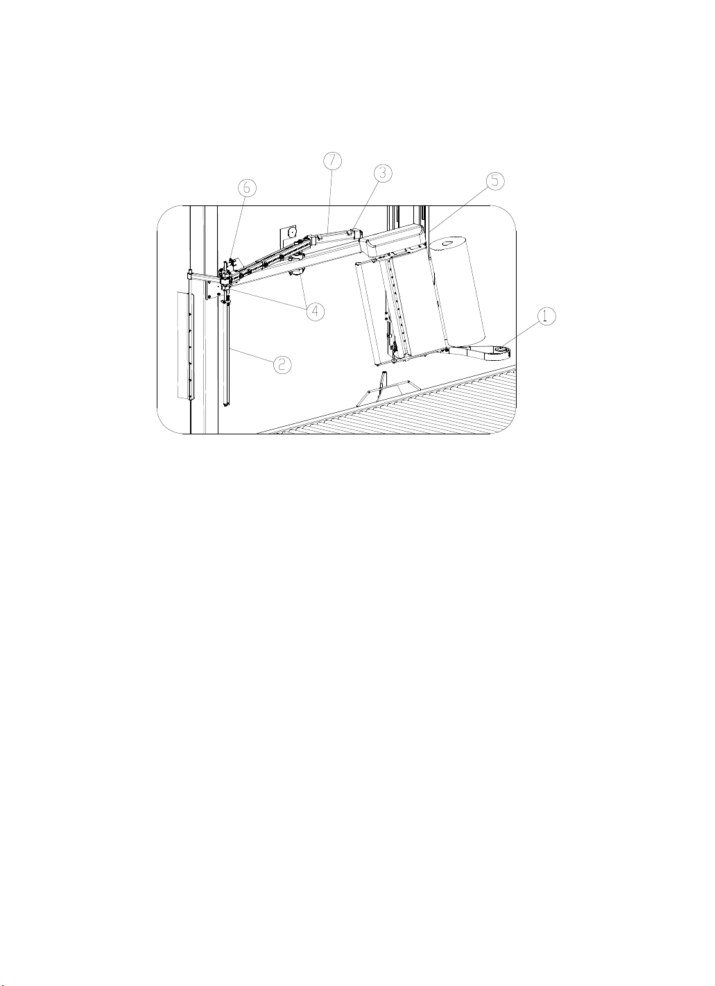
should be on when it arrives in its initial position or to its limit. See Item 3 in Figure 7 on page 30.
Wulftec / M.J. Maillis Group
Page 28 of 36
Version 1.1.1 /May 2013
Page 29

Proximity Sensor Replacement
Removal
Remove the ring gear cover and unscrew the quick-disconnect on the proximity sensor. Loosen the
two (2) lock nuts on the sensor and remove it.
Replacement
Position the sensor until the gap between the sensor head and the counter block on rotary arm is
approximately 1/8 of an inch. Tighten the lower locknut finger tight. Tighten the upper locknut and
reconnect proximity sensor. When all wires and guards (if applicable) have been replaced, turn on
the power and jog the rotary arm by using the arm jog switch. Then verify if the related input blinks.
WARNING! Make sure that the power is disconnected and that a pad-lock is
installed on the main switch of the wrapper before you carry out these operations.
Motor Speed Control
Your Wulftec pallet wrap machine utilizes AC drives, which are controlled by a digital parameter
unit. This unit is used to set the functions such as acceleration/deceleration time and electronic
thermal relay to allow variations in motor operation to best suit the specific application and/or
desired customer wrap parameters.
Wulftec / M.J. Maillis Group
Page 29 of 36
Version 1.1.1 /May 2013
Page 30
Maintenance
General Maintenance
The commutator should be cleaned every two years or every 6000 hours of operation.
Cut/wipe pivot points should be greased (approx. every 6000 hours of operation).
Figure 7 Film in clamp
Carriage Rails
These rails should be greased with all-purpose grease every 2000 hours of operation. See Item 5 in
Figure 7 au-dessus.
Ring Gear
Bearing: Lubrication of the bearing component is provided through the auto-lube system. Operation
of the auto-lube is detailed in the annex. Inspect the grease container of the auto-lube once a month
and refill with EP2 grease as required.
For machines without the auto-lube system, apply EP2 grease with a grease pump every month, or
as part of your regular maintenance program. Move bearing several times to ensure complete fill.
Inspect the seals to ensure they are properly inserted into their grooves and that they are intact and
preventing contaminants from entering the bearing.
Teeth: Visually inspect the teeth once a month. Remove buildup if present. With steel pinion, if
teeth are dry, apply grease with a brush all around ring gear. Use high quality open gear grease
(Mobile Unirex EP2 GCLB or equivalent). With nylon pinion, no greasing is necessary. Backlash
between gear and pinion needs to be kept at approximately .005".
*For cold package; apply EP0 grease
Wulftec / M.J. Maillis Group
Page 30 of 36
Version 1.1.1 /May 2013
Page 31
Maintenance (cont’d)
Chain Maintenance
All chains should be greased every year at the same time as the oil is changed in the reducer. The
chain tension should be checked on a regular basis. The proper tension for the chain is approx.
0.015" of slack for every one (1) foot of chain.
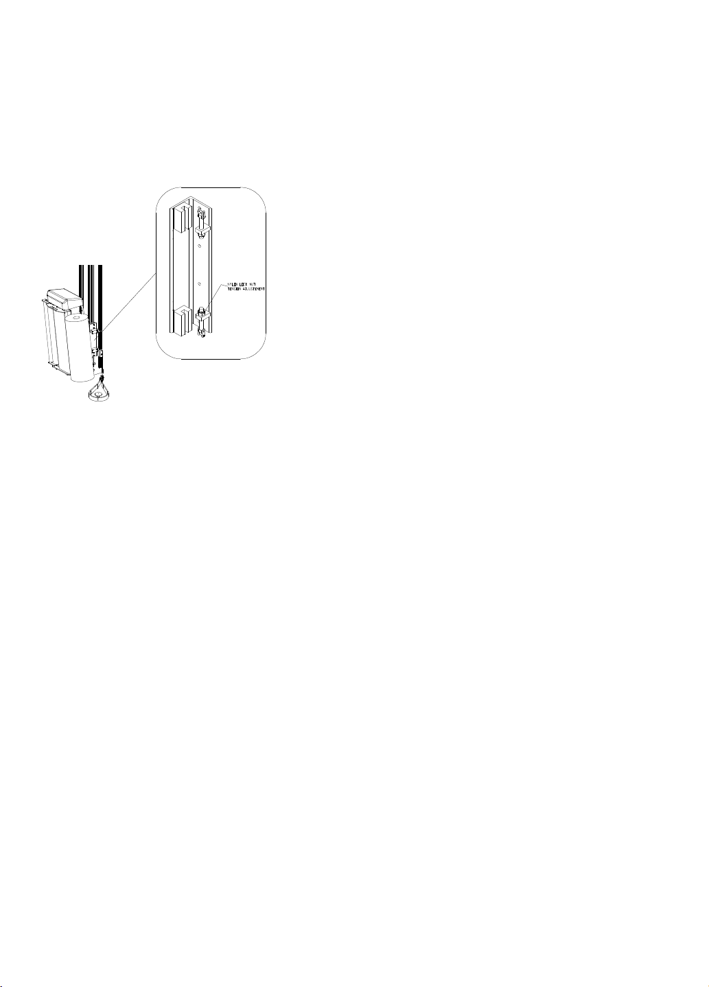
Carriage Lift Chain Tension Adjustments
Position the carriage to the center of the travel limits. Hold
the locknut while tightening the tension-adjusting nut on
the "upper" section. (The lower section is for aligning the vgroove/carriage mounting plates). Do not over tighten and
assure that both chains are equal in tension. (0.015" of
play per foot) Once set, hold the adjustment nut and
tighten the locknut.
Pre-Stretch Belts Adjustment
The pre-stretch belts should be checked for proper tension every 2000 hours of operation.
Recommended tension is 1/64” deflection per inch of belt span with a force of approximately 25 lbs.
The motor drive belt is adjusted by loosening the four (4) motor mounting bolts and sliding the motor
in the mounting slots. The pre-stretch belt tension is adjusted with the tension adjustment arm. This
arm can be rotated and moved within the mounting slot to obtain correct tension.
Pre-Stretch Chain Adjustment
The pre-stretch chains should be checked to ensure the proper tension (approx. every 2000 hours of
operation). If the chains are found to have improper tension they may be adjusted. (0.015” of play
per foot of chain is recommended) The motor chain may be adjusted by loosening the four (4) bolts
from under the top plate of the carriage and moving the motor using the slots provided. The prestretch chain tension may be adjusted by using the cam & sprocket. This cam has an eccentric hole
and may be turned for chain adjustment.
Wulftec / M.J. Maillis Group
Page 31 of 36
Version 1.1.1 /May 2013
Page 32

Maintenance (cont’d)
Filter Regulator
The FR possesses a Filter, which traps the water contained in the air line. A drain plug is located at
the bottom of the filter section. (This function should be done automatically and should not have
to be touched). The second section of the FR contains a Regulator that shows how much air
pressure going is into the machine. The pressure may be regulated by the knob located at the top of
the center section of the FR. This pressure should be set at 80 psi for all Wulftec automatic
machines.
Photoeyes
Every 2000 hours of operation the photoeye and reflectors should be cleaned to ensure that no false
readings would be taken during operation of machinery.
Reducer
The reducers on your equipment are filled with Mobil Glygoyle 460 oil. Do not mix different
lubricants in the reducer. Lubricant incompatibility may result in premature failure. Do not use
Mobil Glygoyle 460 oil if your operating environment requires a different type of oil (ex. cold
temperature environment) or if you have requested a different type of oil in your system.
During the initial start-up operation, a break-in period is necessary before the reducer reaches
maximum operating efficiency. It is recommended to take an oil sample after 1,000 hours of
operation to see if metal shavings or fragments may have accumulated during break-in. If so, change
the oil. Winsmith recommends a gradual application of load during the first several hours after startup. The reducer may run hot during this initial break-in period. This is normal. A few drops of oil
may weep from the lip seals during the break-in stage. After a short period of operation, clean off any
excess oil around the shaft seals and recheck the oil level; adjust if necessary.
Subsequent oil changes should be made after 25,000 hours or as a part of a regular maintenance
program (this frequency is highly application dependent). Note: When changing oil, carefully inspect
used oil to be sure there are no metal shavings, fragments and other signs of excessive wear. Under
severe conditions (rapid temperature changes, moist, dirty, or corrosive environments) it may be
necessary to change the oil at intervals of 1-3 months. Periodic examination of oil samples taken
from the reducer will help establish the appropriate interval.
The oil change procedure for all SE Encore speed reducers is similar. The appropriate oil fill, drain,
and level plugs are identified in chart on following page. Please note that these locations are unique
for each operating position shown. After draining the old lubricant, new lubricant should be added to
the appropriate level plug shown.
Wulftec / M.J. Maillis Group
Page 32 of 36
Version 1.1.1 /May 2013
Page 33
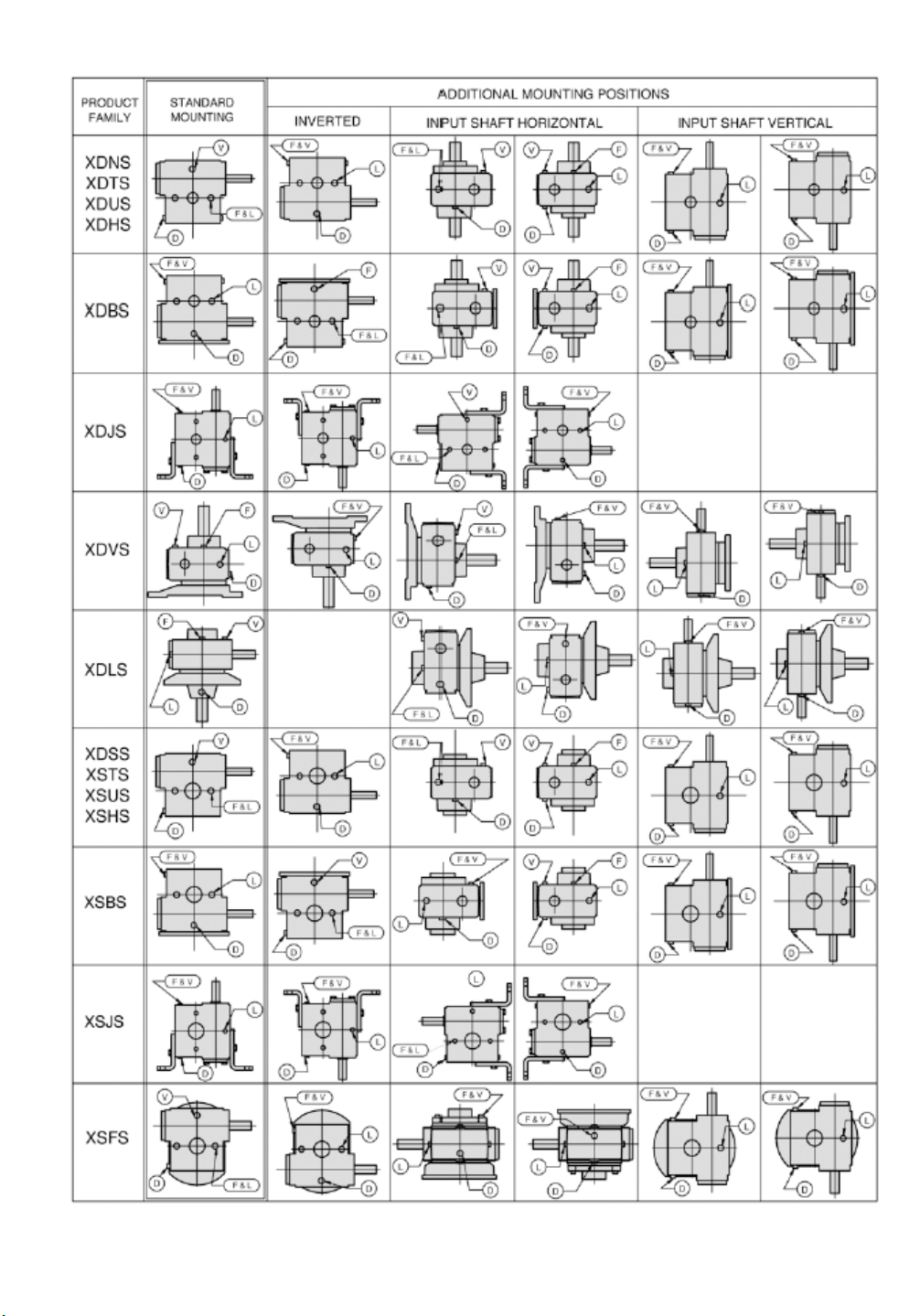
Reducer Chart
Legend: F = Refill Plug V = Vent Plug L = Level Plug D = Drain Plug
Wulftec / M.J. Maillis Group
Page 33 of 36
Version 1.1.1 /May 2013
Page 34

Troubleshooting – WRTA 150
Problems Causes Solutions
Arm not
turning
The reset
sequence does
not stop
•The safety fence door may not be closed.
•Push arm may not be completely
retracted.
•One of the photoeyes may be blocked or
dirty.
•Arm speed on the control panel is set to
zero (0) or too low for the arm to turn.
•Motor fuses may be burned.
•Pinion holding key or motor shaft key is
broken.
• Arm is not at home position and is not
turning.
• Arm is turning but does not stop at
home position.
• Push arm may not be completely
retracted.
• Close and latch the door.
• Refer to Push Arm problems and the
section on Reed Switches adjustment on
page 28.
• Clear the photoeye and/or clean it.
• Increase the arm speed setting located
on the control panel.
• Check for short, if none change the fuse
using the adequate rating.
• Check rotation mechanism, if in proper
order, change the key.
• See Arm not turning problem.
• Check if min speed is set too high.
• See Push arm not moving problem.
Breaker
problem
Load does not
stop centered
Carriage. Does
not stop at the
top of the load
Push arm is
not moving
Carriage
Does Not Go
Up
•Overload - short of wire - defective drive • Check for short. If none found, turn
breaker on for one time. If the breaker
jumps again, call your distributor.
•The system may be set in the pass
through mode.
•The center photoeye may not see the
load
•The infeed safety may not see the load
•The autoheight may be off.
•The photoeye may reflect on something
in the background.
•The flow control may need to be
adjusted. See Item 6 in Figure 7.
•The cylinder may be defective. See Item
7 in Figure 7.
•The valve may be defective.
•The top limit switch on the carriage may
be activated.
•The carriage speed up may be set to
zero (0) or too low for the carriage to
move.
•Motor fuse may be burned.
• Select “Wrapping On” on the touch
screen.
• Clear the photoeye and/or clean it.
• Clear the photoeye and/or clean it.
• Activate the autoheight.
• See Automatic Height Sensing
paragraph.
• Look for kink in the hose. If none,
adjust the valve flow controls.
• Change the defective cylinder.
• Change the defective valve.
• Readjust the limit switch and/or change
the defective switch.
• Increase carriage speed up (located on
the control panel).
• Check for short. If none found, change
the fuse using the appropriate rating.
Carriage stays
at the top
while the arm
continues to
turn
Wulftec / M.J. Maillis Group
•Carriage speed down may be set to zero
(0).
•Bottom limit switch on the carriage may
be activated.
•The carriage could be stuck on the dead
stops.
Page 34 of 36
Version 1.1.1 /May 2013
• Increase carriage speed down (located
on the control panel).
• Readjust the limit switch or change the
defective switch.
• Pull vigorously on the 2 chains at the
same time someone else presses the
Carriage Up button on the touch screen.
Page 35

Problems Causes Solutions
Clamp does
not open after
1-1/2 turns
•Air cylinder does not retract.
•Carriage bottom limit stop may be too
low and the film is wrapping too low
onto the clamp preventing it from
• Look for kink in the hose. If none,
adjust the valve flow controls
• Move the stop block higher for the film
to wrap approx. 5 inches over the clamp
jaws.
opening.
Heat wire does
not cut the
film
Heat wire does
not go back
home
Machine stops
in the middle
of a cycle
•The push arm may not have engaged
completely.
•The fuse may be burned.
•The cut wire may have broken. See Item
2 in Figure 7.
•The flow controls on the cylinders may
need adjusting. See Item 6 in Figure 7.
•There may be a lack of air pressure to
the system.
•The cylinder may be defective. See Item
• Look for the reed switch to make sure
the PLC receives the signal when the
arm is out.
• Check for short, if none, change the
fuse using the appropriate rating
• Change the cut wire with .032 gage
nychrome wire.
• Look for kink in the hose. If none are
found adjust the flow control on the
cylinder.
• Look for the air pressure gage it should
not be below 80PSI
• Change the defective cylinder.
7 in Figure 7.
•The flow controls on the cylinders may
need adjusting.
•There may be a lack of air pressure to
the system
•The cylinder may be defective.
• Look for kink in the hose. If none,
adjust the valve flow control.
• Look for the air pressure gage should
not be below 80 PSI.
• Change the defective cylinder.
•An alarm is activated. • Look for the alarm on the touch
screen, take the corrective measure;
then accept the alarm and restart the
cycle.
Motor on film
tension never
stops turning
Motor on film
tension never
turns
•The steel cam is not touching the analog
sensor when the dancer bar is at rest
position.
•The minimum speed trim pot on the
pre-stretch drive is not set to minimum.
•The tension adjustment spring on the
side of the carriage is set too light.
•The clamp is open.
•The motor fuse is burned.
•The motor fuse is off.
•The fuse on the analog board is burned.
•Analog sensor may be defective.
•Turn the steel cam closer to the analog
sensor or move the analog sensor
toward the cam. The analog sensor and
the cam are situated under the red
cover on the film carriage.
• Turn the minimum speed trim pot
counter clockwise on the pre-stretch
drive.
• Increase pressure on the spring by
turning the knob clockwise.
• Close the clamp.
• Check for short, if none, change the
fuse using the appropriate rating
• Turn on the motor fuse.
• Check for short, if none, change the
fuse using the appropriate rating
• Call technical service at Wulftec.
Wulftec / M.J. Maillis Group
Page 35 of 36
Version 1.1.1 /May 2013
Page 36

Problems Causes Solutions
Power light is
not on
• Main fuse is OFF.
• Light bulb may be burned out.
• Main switch is in the off position
• Main fuses are burned.
• Related glass fuse is burned.
• Turn on the main fuse.
• Change the light bulb.
• Turn the switch to the on position.
• Check for short, if none change the
main fuse using the right rating.
• Check for short, if none change the fuse
using the right rating.
Start (blue)
light does not
come on after
pushing on
start.
• Light bulb may be burned out.
• An alarm might be activated.
• One of the automatic modes was not
engaged. (Wrapping or passthrough.)
• Change the light bulb.
• Accept the alarm.
• Make sure that the machine is in
automatic mode and that a reset was
done.
If you cannot find a solution to your problem with this guide, please contact your distributor.
Wulftec / M.J. Maillis Group
Page 36 of 36
Version 1.1.1 /May 2013
Page 37
Page 38
Page 39
Page 40
Page 41
Page 42
Page 43
Page 44
Page 45
Page 46
Page 47
Page 48
Page 49
Page 50
Page 51
Page 52
Page 53
Page 54
Page 55
Page 56
Page 57
Page 58
Page 59
Page 60
Page 61
Page 62
Page 63
Page 64
Page 65
Page 66
Page 67
Revision
0 PRODUCTION
Date
11/01/2006
Name
A.B.
Verified By: GUY LOPES
6EPAN03622
WULFTEC M.J. MAILLIS
WULFTEC MJ MAILLIS
209 WULFTEC
QUEBEC, CANADA
Page Title:
Dwg. No.:
TITLE PAGE
200
Drawn By: ANDRE BUREAU
Page: 200SMART SERIES WRTA
Model
Responsible for project
Created on:
Edited on:
SMART SERIES WRTA
ANDRE BUREAU
Number of pages 29
6EPAN03622
03/04/2014
:
:
:
Edited by
Project name
Company/customer WULFTEC M.J. MAILLIS:
07/02/2013
WULFTEC MJ MAILLIS
209 WULFTEC
AYER'S CLIFF
1-877-WULFTEC
andreb
Tel.:
QUEBEC, CANADA
:
:
Address:
J0B 1C0
Guy Lopes
I
N
G
Q
U
E
E
N
115938
B
I
E
C
E
U
R
Production floor
electrical builder :
E
D
C
B
A
1 2 3 4 5 6 7 8 9 10
Page 68
Revision
0 PRODUCTION
Date
11/01/2006
Name
A.B.
Verified By: GUY LOPES
6EPAN03622
WULFTEC M.J. MAILLIS
WULFTEC MJ MAILLIS
209 WULFTEC
QUEBEC, CANADA
Page Title:
Dwg. No.:
REVISION HISTORY
201
Drawn By: ANDRE BUREAU
Page: 201SMART SERIES WRTA
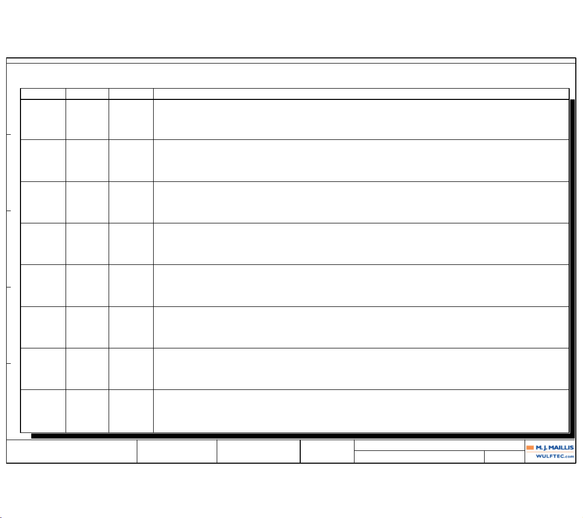
PROJECT REVISION HISTORY
Rev. Number
Date
A. BUREAU0 05/25/2012 PRODUCTION
Reviser Revision Status
1 03/14/2013 A.B. UPDATE POWER SUPPLY
2 07/02/2013 A.B. UPDATE TO HEAT WIRE FUSE
E
D
C
B
A
1 2 3 4 5 6 7 8 9 10
Page 69
Revision
0 PRODUCTION
Date
11/01/2006
Name
A.B.
Verified By: GUY LOPES
6EPAN03622
WULFTEC M.J. MAILLIS
WULFTEC MJ MAILLIS
209 WULFTEC
QUEBEC, CANADA
Page Title:
Dwg. No.:
TABLE OF CONTENTS: (200 - 228)
202
Drawn By: ANDRE BUREAU
Page: 202SMART SERIES WRTA
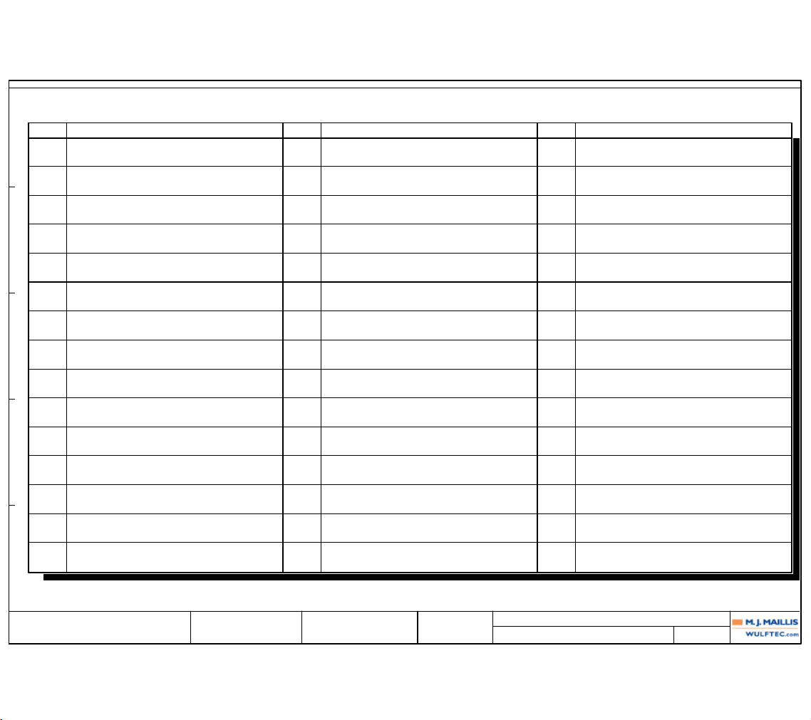
Page Designation
TABLE OF CONTENTS
Page
Designation Page Designation
200 TITLE PAGE
201 REVISION HISTORY
202 TABLE OF CONTENTS: (200 - 228)
203 MAIN POWER DISTRIBUTION
204 120VAC AND 24VDC DISTRIBUTION
205 DC AND PLC
206 PANEL DOOR
207 RELAY AND SPARES
208 PRESTRETCH
209 CARRIAGE
210 ROTATION
211 BACKPLATE TO QUICK PLUG
212 WRTA CONTROL
213 SPARE I/O
214 IO List: PLC-01 ( - )
215 IO List: PLC-02 ( - )
216 IO List: PLC-03 ( - )
217 SWITCH BOARD FRONT VIEW
218 SWITCH BOARD BACK VIEW
219 PANEL LAYOUT
220 QUICK PLUG PIN CHART: QP-01
221 QUICK PLUG PIN CHART: QP-02
222 TERMINAL DIAGRAM: TB-01
223 TERMINAL DIAGRAM: TB-02
224 TERMINAL DIAGRAM: TB-04
225 TERMINAL DIAGRAM: TB-06
226 TERMINAL DIAGRAM: TB-200
227 DEVICE LIST: (BR-01 - SW-01)
228 DEVICE LIST: (SW-02 - VFD-03)
E
D
C
B
A
1 2 3 4 5 6 7 8 9 10
Page 70
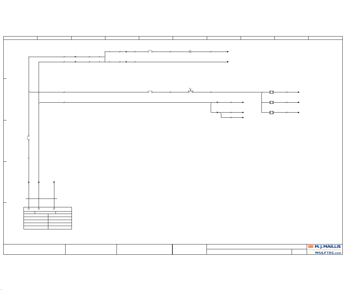
MAIN POWER DISTRIBUTION
203
WULFTEC MJ MAILLIS
209 WULFTEC
ANDRE BUREAU 6EPAN03622
QUEBEC, CANADA
GUY LOPES
0 11/01/2006 A.B.PRODUCTION
203
WULFTEC M.J. MAILLIS
SMART SERIES WRTA
Revision Date Name
Drawn By:
Verified By:
Page Title:
Dwg. No.: Page:
1
0
2
2
0
2
0
3 3
6
4
7
7
7
0
5
8
9
10
0
0
0
#14 AWG
BLK
#14 AWG
BLK
#JUMPER
METAL
4TB-02 1TB-02
120V 60 Hz 1 Ph
15A
3.4A
3
120V
CBL-01
3C14
SJOOW
30FT EXT
BLK WHT GRN
L1 N
7TB-02
FREQ.:
TOTAL FLA:
LARGEST MTR FLA:
kA RMS SYM:
AT VOLTAGE:
GND
PHASE:
SPECIAL:
(207A6)
MCR-01
L1 T1
(208A1)
VFD-01:L1
(208A1)
VFD-01:L2
#14 AWG
BLK
#14 AWG
BLK
#14 AWG
WHT
21
TB-06 3
TB-06 4
T-01
120-240VAC
2KVA
H2
H1
X1
X2(H1)
#XFO
WHT
#XFO
BLK
CB-01
15A/277V
T1
L1
#14 AWG
BLK
#XFO
BRN
FU-05
5A 125VAC
1 2
(206D3)
SWL-01
14 13
TB-02 2
3
(205D3)
PLC-01:L1
(204A1)
PWS-01:L
(204D1)
CR-01:14
(205D3)
PLC-01:N
(204A1)
PWS-01:N
(204D1)
TB-04:1
FU-03
2A 250VAC
1 2
FU-04
2A 250VAC
1 2
#14 AWG
BLK
#14 AWG
BLK
#18 AWG
BLK
#18 AWG
BLK
#14 AWG
BLK
#14 AWG
WHT
#14 AWG
WHT
#14 AWG
WHT
#14 AWG
BLK
#14 AWG
WHT
#XFO
WHT
CB-02
10A
48VDC/
277VAC
T1 L1
CB-03
10A
48VDC/
277VAC
T1 L1
E
D
C
B
A
1 2 3 4 5 6 7 8 9 10
Page 71
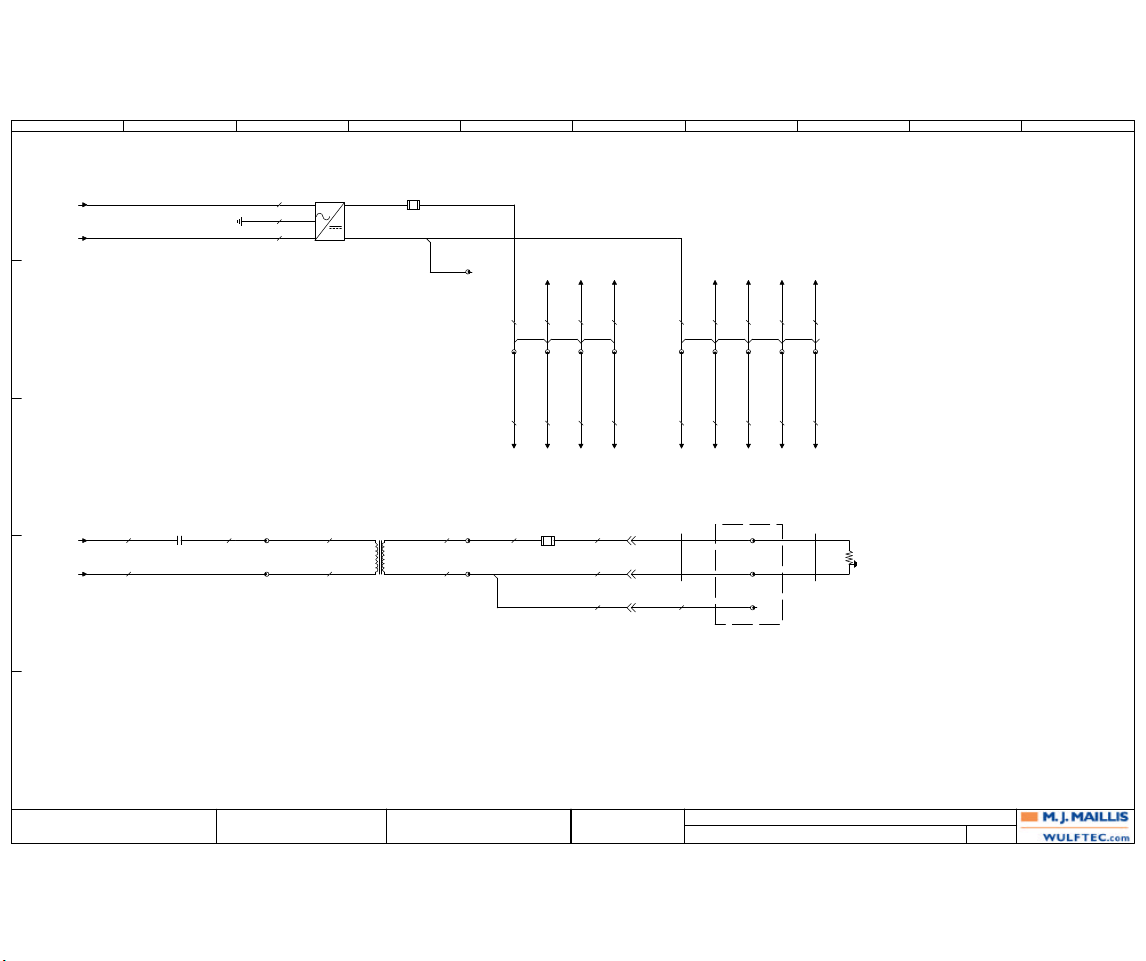
120VAC AND 24VDC DISTRIBUTION
204
WULFTEC MJ MAILLIS
209 WULFTEC
ANDRE BUREAU 6EPAN03622
QUEBEC, CANADA
GUY LOPES
0 11/01/2006 A.B.PRODUCTION
204
WULFTEC M.J. MAILLIS
SMART SERIES WRTA
Revision Date Name
Drawn By:
Verified By:
Page Title:
Dwg. No.: Page:
21
0
21
20
00
22
24V
22
00
23
0V
24V 24V
0V
0V
0V
24V 24V
24V
0V
0V 0V
9
10
0
0
0V
0V
24V
0V
24V 24V
0V
#18 AWG
BLK
#14 AWG
GRN
#14 AWG
WHT
PWS-01
120VAC/24VDC
2.5A 60W
POWER SUPPLY
AC
DC
LN+
-
GND
#18 AWG
BLU
1TB-01
#20 AWG
BLU
(205E3)
PLC-01:1L
(206B1)
PB-01:14
#20 AWG
BLU
2
#20 AWG
BLU
(211A1)
QP-01:1
3
#20 AWG
BLU
(207A3)
TD-01:18
#20 AWG
BLU
(212B1)
QP-02:1
#18 AWG
BLU/WHT
5TB-01
#20 AWG
BLU
(205E3)
PLC-01:1M
(211B1)
QP-01:2
#18 AWG
BLU/WHT
6
#18 AWG
BLU/WHT
7
#18 AWG
BLU/WHT
(207A7)
MCR-01:A2
#18 AWG
BLU/WHT
9
(212B1)
QP-02:2
FU-01
2A 250VAC
1 2
(207B6)
CR-01
HEAT WIRE
14 11
#14 AWG
RED
TB-04 2
1
#XFO WIRE
BLK
#XFO WIRE
WHT
T-02
120VAC-24VAC
250VA
HEAT WIRE
H1H4X1
X4
#XFO WIRE
RED
#XFO WIRE
YEL
TB-04 3
4
#14 AWG
BLK
FU-02
15A 125VAC
1 2
#14 AWG
BLK
#14 AWG
WHT
#14 AWG
GRN
QP-02
1515
1616
PEPE
TB-02 8
#18 AWG
BLU/WHT
#14 AWG
GRN
CBL-77
2C14
PVC SHIELD
WHT
BLK
JB-200
WRAP ZONE
TB-200 20
21
22
CBL-78
2C14
SJOW
WHT
BLK
HW-01
HEAT WIRE
(203B9)
FU-04:2
(203B9)
FU-05:2
(203B8)
TB-02:3
(203B8)
TB-02:3
(208A1)
VFD-01:28
VFD-01:11
(209A1)
VFD-02:9
(210A1)
VFD-03:28
8
#18 AWG
BLU/WHT
#14 AWG
BLK
#14 AWG
WHT
(206C7)
HMI-01:+
(206C10)
HMI-01:-
#18 AWG
BLU
#18 AWG
BLU/WHT
4
(208A1)
VFD-01:21
VFD-01:19
(206D1)
SWL-01:x2
#18 AWG
BLU/WHT
#18 AWG
BLU
E
D
C
B
A
1 2 3 4 5 6 7 8 9 10
Page 72
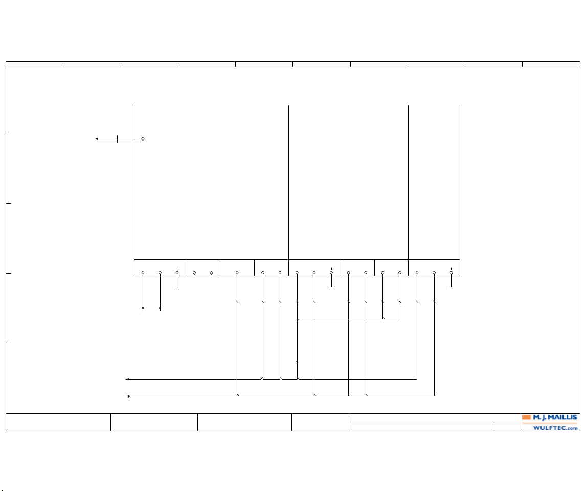
DC AND PLC
205
WULFTEC MJ MAILLIS
209 WULFTEC
ANDRE BUREAU 6EPAN03622
QUEBEC, CANADA
GUY LOPES
0 11/01/2006 A.B.PRODUCTION
205
WULFTEC M.J. MAILLIS
SMART SERIES WRTA
Revision Date Name
Drawn By:
Verified By:
Page Title:
Dwg. No.: Page:
24V
0V 0V
24V
0V
8
0
24V 24V
24V
24V
24V
(204C5)
TB-01:1
(204C6)
TB-01:5
#20 AWG
BLU
#20 AWG
BLU
#18 AWG
BLU/WHT
#18 AWG
BLU/WHT
#20 AWG
BLU
#20 AWG
BLU
6ES7 214-1BD23-0XB0
S7-1200 CPU 1214C AC/DC/RLY
PLC-01
L1
L1
N
N
GND
GND
BACKPLATE METAL
L+L+M
M
1M
1M
1L1L2L
2L
S7-1200 SM 1223 8 IN 8 OUT DC/RLY
6ES7-223-1PH32-0XB0
PLC-02
L+L+MM GND
GND
1M1M2M
2M
BACKPLATE METAL
1L1L2L
2L
S7-1200 SM 1232 4 ANALOG OUTPUT
6ES7-232-4HD32-0XB0
PLC-03
L+L+MMGND
GND
BACKPLATE METAL
(203B9)
FU-03:2
(203B8)
TB-02:2
#18 AWG
BLU/WHT
#20 AWG
BLU
#18 AWG
BLU/WHT
#20 AWG
BLU
#20 AWG
BLU
#20 AWG
BLU
(206C10)
HMI-01:
CBL-80
NETWORK
CABLE
ENET
RJ-45
ETHERNET PORT
E
D
C
B
A
1 2 3 4 5 6 7 8 9 10
Page 73
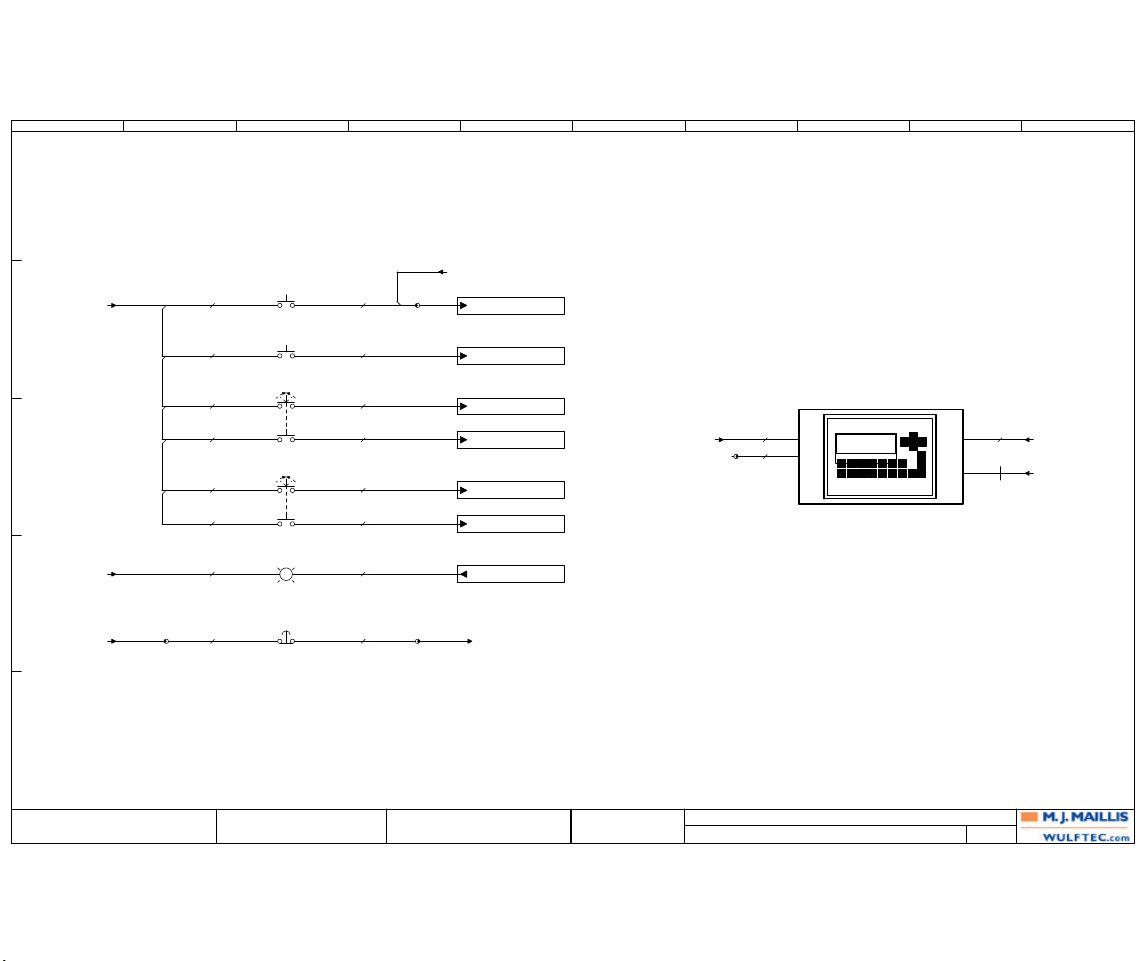
PANEL DOOR
206
WULFTEC MJ MAILLIS
209 WULFTEC
ANDRE BUREAU 6EPAN03622
QUEBEC, CANADA
GUY LOPES
0 11/01/2006 A.B.PRODUCTION
206
WULFTEC M.J. MAILLIS
SMART SERIES WRTA
Revision Date Name
Drawn By:
Verified By:
Page Title:
Dwg. No.: Page:
47
24V 24V 24V 24V 24V
48
46
45
44
43
42
41
40 40 24V
0V
47 48
40
24V 0V
PB-02
E-STOP
12 11
I00.1
START/STOP
PLC-01
CARRIAGE
UP DOWN
14 13
PB-01
START/STOP
14 13
SW-02
24 23
SWL-01
(203B6)
STATUS
POWER
OFF ON
x2 x1
REINF MANUAL
WRAP ROT
14 13
(204B5)
TB-01:2
(204B7)
TB-01:7
I00.4
LOWER CARRIAGE
PLC-01
I00.3
RAISE CARRIAGE
PLC-01
I00.7
REINF. WRAP
PLC-01
SW-01
24 23
(210C6)
QP-01:10
(212A1)
QP-02:3
I08.3
RESET
PLC-02
PB-03
RESET
14 13
TB-02 5 TB-02 6
PLC-01
Q00.0
POWER / WRAPPER STATUS
I08.6
ROTATION JOG
PLC-02
#20 AWG
BLU
#20 AWG
BLU
#20 AWG
BLU
#20 AWG
BLU
#20 AWG
BLU
#20 AWG
BLU
#20 AWG
BLU
#20 AWG
BLU
#20 AWG
BLU
#20 AWG
BLU
#20 AWG
BLU
#20 AWG
BLU
#20 AWG
BLU
#18 AWG
BLU/WHT
#20 AWG
BLU
#20 AWG
BLU
(210C6)
QP-01:11
TB-01 10
HMI-01
+ -
PE
(204B6)
TB-01:4
(204B8)
TB-01:9
TB-02 9
#18 AWG
BLU
#14 AWG
GRN
#18 AWG
BLU/WHT
(205B2)
PLC-01:RJ-45
CBL-80
NETWORK
CABLE
ENET
SIEMENS
E
D
C
B
A
1 2 3 4 5 6 7 8 9 10
Page 74
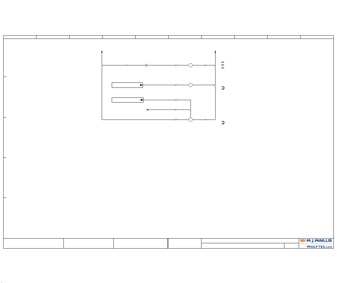
RELAY AND SPARES
207
WULFTEC MJ MAILLIS
209 WULFTEC
ANDRE BUREAU 6EPAN03622
QUEBEC, CANADA
GUY LOPES
0 11/01/2006 A.B.PRODUCTION
207
WULFTEC M.J. MAILLIS
SMART SERIES WRTA
Revision Date Name
Drawn By:
Verified By:
Page Title:
Dwg. No.: Page:
24V
51
50
52
0V
0V
52
0V
24V
MCR-01
MAIN
CONTACTOR
L1 T1
(203A6)
L2 T2
L3 T3
A1 A2
(212A9)
QP-02:4
(204B7)
TB-01:8
TD-01
16
15
18
(207A5)
MODE B
RANGE 10
SET TO 50%
A1 A2
B1
(204B6)
TB-01:3
(207C6)
TD-01
QUICK STOP TIMER
MODE B
RANGE 10
SET TO 50%
18 15
Q08.6
POWER ON
HEAT WIRE
PLC-02
CR-01
HEAT WIRE
12
11
14
(204D2)
A1 (5) A2 (1)
#20 AWG
BLU
#20 AWG
BLU
#20 AWG
BLU
#20 AWG
BLU
#20 AWG
BLU
#18 AWG
BLU/WHT
#20 AWG
BLU
I00.0
E-STOP
PLC-01
#20 AWG
BLU
E
D
C
B
A
1 2 3 4 5 6 7 8 9 10
Page 75
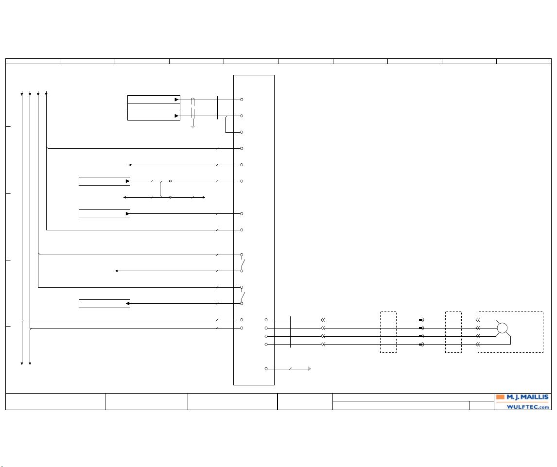
PRESTRETCH
208
WULFTEC MJ MAILLIS
209 WULFTEC
ANDRE BUREAU 6EPAN03622
QUEBEC, CANADA
GUY LOPES
0 11/01/2006 A.B.PRODUCTION
208
WULFTEC M.J. MAILLIS
SMART SERIES WRTA
Revision Date Name
Drawn By:
Verified By:
Page Title:
Dwg. No.: Page:
61
64
62
61
94
60
0 0
5 5
0V
0V
61 61
24V
24V
63
VFD-01
GND
(211C1)
QP-01:6
(203A7)
MCR-01:T1
(203A7)
TB-06:2
(209A1)
VFD-02:L1
(209A1)
VFD-02:L2
Q00.7
ACKNOWLEDGE FAULT(S)
PLC-01
Q00.1
START PRESTRETCH
PLC-01
I08.5
LACK OF FILM
PLC-02
L1
L2
U
V
W
GND
GND
CBL-03
4C16
PVC SHLD
GRN
RED
WHT
BLK
QP-01
1414
1515
1616
1717
MTR-01
PRE-STRETCH MTR
3Ph
M
T1
T2
T3
G
JB-100
ROTARY ARMFRAME
JB-101 JB-102
CARRIAGE
#14 AWG
BLK
#14 AWG
WHT
(204C7)
TB-01:6
TB-01:6
(210B4)
VFD-03:7
TB-01 11
12
(209B3)
VFD-02:7
#20 AWG
BLU
#20 AWG
BLU
#14 AWG
GRN
#20 AWG
BLU
FILM TENSION
0
PLC-03
0
0M
PLC-03
0M
BACKPLATE METAL
CBL-02
2C18
PVC SHLD (DC)
RED
BLK
3 AIN1+
4 AIN COM
2
11 AIN2-
10 AIN2+
5 START
28 0VDC
19 DRIVE FAULT
20
21 LACK OF FILM
22
7 CLR FAULT
(204C6)
TB-01:4
TB-01:4
(209C3)
VFD-02:10
#20 AWG
BLU
#18 AWG
BLU
#20 AWG
BLU
#18 AWG
BLU
#18 AWG
BLU/WHT
#20 AWG
BLU
#20 AWG
BLU
#20 AWG
BLU
#18 AWG
BLU/WHT
E
D
C
B
A
1 2 3 4 5 6 7 8 9 10
Page 76
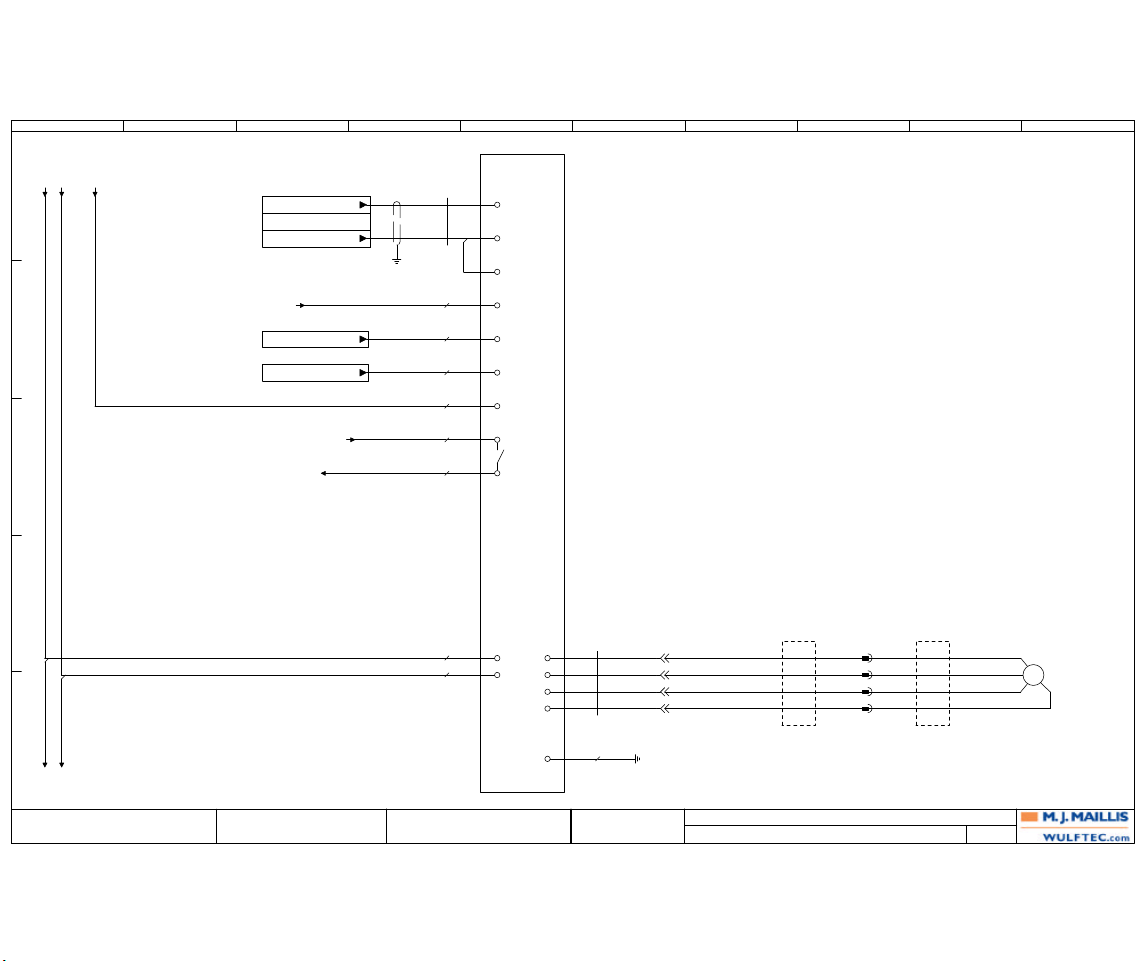
CARRIAGE
209
WULFTEC MJ MAILLIS
209 WULFTEC
ANDRE BUREAU 6EPAN03622
QUEBEC, CANADA
GUY LOPES
0 11/01/2006 A.B.PRODUCTION
209
WULFTEC M.J. MAILLIS
SMART SERIES WRTA
Revision Date Name
Drawn By:
Verified By:
Page Title:
Dwg. No.: Page:
71
70
73
0 0
5 5
0V
61
63
72
VFD-02
Q00.2
CARRIAGE UP
PLC-01
Q00.3
CARRIAGE DOWN
PLC-01
(208E1)
VFD-01:L1
(208E1)
VFD-01:L2
(210A1)
VFD-03:L1
(210A1)
VFD-03:L2
L1
L2
U
V
W
GND
GND
JB-100
FRAME
JB-101
ROTARY ARM
CBL-05
4C16
PVC SHLD
GRN
RED
WHT
BLK
GND
QP-01
1818
1919
2020
2121
MTR-02
CARRIAGE UP/DWN MTR
3Ph
M
T1
T2
T3
G
(204C7)
TB-01:7
(208C4)
TB-01:12
#14 AWG
GRN
#14 AWG
WHT
#14 AWG
BLK
#20 AWG
BLU
#20 AWG
BLU
#20 AWG
BLU
CARRIAGE
SPEED REFERENCE 1
PLC-03
1
1M
PLC-03
1M
BACKPLATE METAL
CBL-04
2C18
PVC SHLD (DC)
RED
BLK
3 AIN+
4
AIN-
2
5 UP
6
DOWN
9 0VDC
10
11
7 CLR FAULT
#18 AWG
BLU/WHT
(208D3)
VFD-01:20
(210C3)
VFD-03:19
#20 AWG
BLU
#20 AWG
BLU
E
D
C
B
A
1 2 3 4 5 6 7 8 9 10
Page 77
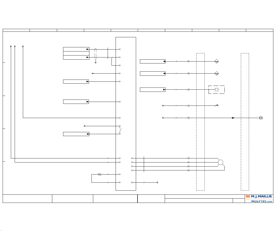
ROTATION
210
WULFTEC MJ MAILLIS
209 WULFTEC
ANDRE BUREAU 6EPAN03622
QUEBEC, CANADA
GUY LOPES
0 11/01/2006 A.B.PRODUCTION
210
WULFTEC M.J. MAILLIS
SMART SERIES WRTA
Revision Date Name
Drawn By:
Verified By:
Page Title:
Dwg. No.: Page:
83
81
84
85
86
80
89
88
87
0
5
47
0V
40
61
72
Q00.4
ROTATION FWD
PLC-01
VFD-03
Q00.6
QUICK STOP
PLC-01
BR-01
1HP
230VAC
L1
L2
U
V
W
GND
GND
GND
(209E1)
VFD-02:L1
(209E1)
VFD-02:L2
CBL-07
4C16
PVC SHLD
GRN
RED
WHT
BLK
QP-01
2222
2323
2424
PEPE
MTR-03
ROTATION MTR
3Ph
M
T1
T2
T3
G
JB-100
FRAME
(204C7)
TB-01:8
I08.4
COUNT POSITION SENSOR
PLC-02
I01.0
HOME POSITION
PLC-01
Q08.5
BEACON LIGHT
PLC-02
#20 AWG
BLU
#20 AWG
BLU
#20 AWG
BLU
#20 AWG
BLU
QP-01
77
99
88
1111
PS-03
COUNT POSITION
BLK
PS-01
HOME POSITION
BLK
FRAME
JB-201
BCN-01
1 0
PC-01
PULL CORD (START/STOP)
14 13
(206D1)
TB-02:5
#20 AWG
BLU
1010
PE-03
ROTARY ARM
BUMPER
BLK
JB-101
ROTARY ARM
BR+
BR-
(206B4)
TB-01:10
(208C3)
TB-01:12
#14 AWG
BLK
#14 AWG
WHT
#BR-01
WIRES
#BR-01
WIRES
#14 AWG
GRN
ROTARY ARM
SPEED REFERENCE 2
PLC-03
2
2M
PLC-03
2M
BACKPLATE METAL
CBL-06
2C18
PVC SHLD (DC)
RED
BLK
3 AIN+
4
AIN-
2
5 FWD
8
QUICK STOP
28 0VDC
19
20
7 CLR FAULT
(209C3)
VFD-02:11
I01.1
DRIVE FAULT
PLC-01
E
D
C
B
A
1 2 3 4 5 6 7 8 9 10
Page 78
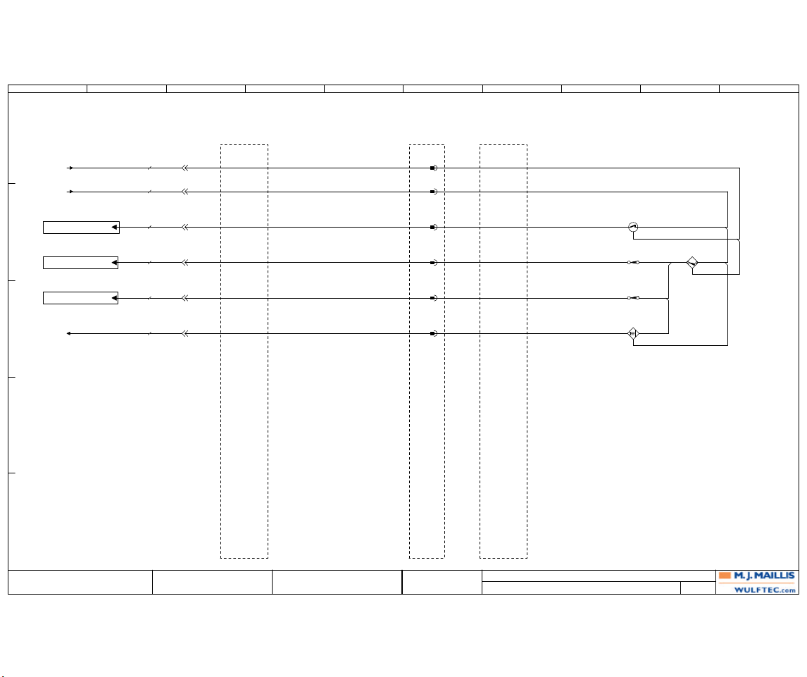
BACKPLATE TO QUICK PLUG
211
WULFTEC MJ MAILLIS
209 WULFTEC
ANDRE BUREAU 6EPAN03622
QUEBEC, CANADA
GUY LOPES
0 11/01/2006 A.B.PRODUCTION
211
WULFTEC M.J. MAILLIS
SMART SERIES WRTA
Revision Date Name
Drawn By:
Verified By:
Page Title:
Dwg. No.: Page:
102
101
100
24V
24V
60
24V
0V
(204C5)
TB-01:2
(204B7)
TB-01:6
44
55
66
(208B3)
VFD-01:10
I00.5
CARRIAGE RAISED
PLC-01
I00.6
CARRIAGE LOWERED
PLC-01
QP-01
11
22
33
#20 AWG
BLU
#18 AWG
BLU/WHT
#20 AWG
BLU
#20 AWG
BLU
#20 AWG
BLU
JB-100
FRAME
PAGE 400+
SLIP-RING
ROTARY ARM
PAGE 400+
JB-101
ROTARY ARM
PAGE 400+
PE-01
AUTOHEIGHT
WHT
BRN
BLU
LS-01
CARRIAGE RAISED
12 11
LS-02
CARRIAGE LOWERED
12 11
AS-01
FORCE TO LOAD
0-10 V
BLK BRN
BLU
JB-102
CARRIAGE
PAGE 300+
PS-02
DOOR CLOSED
BLK
BRN
BLU
#20 AWG
BLU
I00.2
AUTOHEIGHT PHOTO-EYE
PLC-01
E
D
C
B
A
1 2 3 4 5 6 7 8 9 10
Page 79
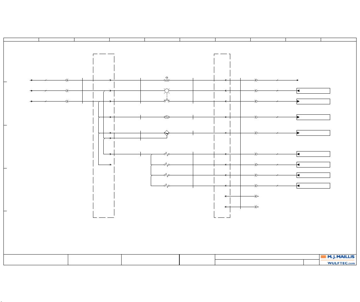
WRTA CONTROL
212
WULFTEC MJ MAILLIS
209 WULFTEC
ANDRE BUREAU 6EPAN03622
QUEBEC, CANADA
GUY LOPES
0 11/01/2006 A.B.PRODUCTION
212
WULFTEC M.J. MAILLIS
SMART SERIES WRTA
Revision Date Name
Drawn By:
Verified By:
Page Title:
Dwg. No.: Page:
117
116
115
114
113
112
111
110
52
24V
48
0V
(204C6)
TB-01:3
(204C8)
TB-01:9
(206D5)
TB-02:6
I08.0
PUSH ARM EXTENDED
PLC-02
I08.1
PUSH ARM RETRACTED
PLC-02
I08.2
FILM CLAMP
OPEN/CLOSE
PLC-02
PLC-02
ROTARY ARM AT HOME
Q08.4
PLC-02
EXTEND PUSH ARM
Q08.0
PLC-02
RETRACT PUSH ARM
Q08.1
PLC-02
EXTEND WIPE ARM
Q08.2
PLC-02
FILM CLAMP
Q08.3
(207B5)
TD-01:B1
#20 AWG
BLU
#18 AWG
BLU/WHT
#20 AWG
BLU
#20 AWG
BLU
#20 AWG
BLU
#20 AWG
BLU
#20 AWG
BLU
#20 AWG
BLU
#20 AWG
BLU
#20 AWG
BLU
#20 AWG
BLU
#20 AWG
BLU
QP-02
33
22
11
CBL-16
19C18
PVC SHLD
(212A7)
WHT
RED
BLK
JB-01
WRAP ZONE
TB-200 8
5
1
2
3
6
7
4
CBL-17
7C18
PVC SHLD
(212A6)
RED
BLK
WHT
RS-01
BRN
CBL-18
BLU
BRN
CBL-19
SMC
DB-25
ORG/RED
PB-04
E-STOP
12 11
PBL-01
X2 X1
FILM CLAMP OPEN/CLOSE
ROTARY ARM AT HOME POSITION
13 14
RS-01
PUSH ARM EXTENDED
BRN BLU
PS-04
PUSH ARM RETRACTED
BRN BLK
BLU
SOL-01
PUSH ARM
ORG/RED BLK
SOL-01
PUSH ARM
YEL/BLK
A
B
SOL-02
WIPE ARM
BRN
SOL-03
FILM CLAMP
RED
CBL-17
(212A4)
BLU
ORG
GRN
JB-01
WRAP ZONE
RS-01
BLU
CBL-18
BLK
CBL-19
RED
BRN
YEL/BLK
BLK
TB-200 9
CBL-16
(212A3)
BLU
ORG
GRN/WHT
RED/WHT
BLK/WHT
BLU/BLK
ORG/BLK
GRN/BLK
RED/BLK
WHT/BLK
GRN
12
13
14
15
16
17
18
19
10
11
QP-02
44
77
88
99
1010
1111
1212
1313
1414
55
66
E
D
C
B
A
1 2 3 4 5 6 7 8 9 10
Page 80
SPARE I/O
213
WULFTEC MJ MAILLIS
209 WULFTEC
ANDRE BUREAU 6EPAN03622
QUEBEC, CANADA
GUY LOPES
0 11/01/2006 A.B.PRODUCTION
213
WULFTEC M.J. MAILLIS
SMART SERIES WRTA
Revision Date Name
Drawn By:
Verified By:
Page Title:
Dwg. No.: Page:
AI:00
SPARE ANALOG IN
PLC-01
AI:01
SPARE ANALOG IN
PLC-01
I08.7
SPARE
PLC-02
I01.5
SPARE
PLC-01
I01.2
SPARE
PLC-01
I01.3
SPARE
PLC-01
I01.4
SPARE
PLC-01
SPARE
Q01.1
PLC-01
SPARE
Q01.0
PLC-01
SPARE
Q08.7
PLC-02
SPARE
3
PLC-03
3
3M
PLC-03
3M
Q00.5
SPARE
PLC-01
E
D
C
B
A
1 2 3 4 5 6 7 8 9 10
Page 81
Revision
0 PRODUCTION
Date
11/01/2006
Name
A.B.
Verified By: GUY LOPES
6EPAN03622
WULFTEC M.J. MAILLIS
WULFTEC MJ MAILLIS
209 WULFTEC
QUEBEC, CANADA
Page Title:
Dwg. No.:
IO List: PLC-01 ( - )
214
Drawn By: ANDRE BUREAU
Page: 214SMART SERIES WRTA
IO List: PLC-01 ( - )
I/O ADDRESS FUNCTION TEXT
CIRCUIT
NUMBER
FIRST TARGET FUNCTION TEXT OF LAST TARGET
LAST TARGET PAGE
I00.0 E-STOP
BLU
52 TD-01:B1 TD-01 QUICK STOP TIMER (207B5)
I00.1 START/STOP
BLU
40 TB-01:10 PB-01 START/STOP (206B5)
I00.2 AUTOHEIGHT PHOTO-EYE
BLU
100 QP-01:3 PE-01 AUTOHEIGHT (211B2)
I00.3 RAISE CARRIAGE
BLU
45 SW-01:13 SW-01 CARRIAGE UP DOWN (206C5)
I00.4 LOWER CARRIAGE
BLU
44 SW-01:23 SW-01 CARRIAGE UP DOWN (206C5)
I00.5 CARRIAGE RAISED
BLU
101 QP-01:4 LS-01 CARRIAGE RAISED (211B2)
I00.6 CARRIAGE LOWERED
BLU
102 QP-01:5 LS-02 CARRIAGE LOWERED (211C2)
I00.7 REINF. WRAP
BLU
43 SW-02:13 SW-02 REINF MANUAL WRAP ROT (206C5)
I01.0 HOME POSITION
BLU
88 QP-01:9 PS-01 HOME POSITION (210B6)
I01.1 DRIVE FAULT 84 VFD-03:20 VFD-03 ROTATION DRIVE (210D4)
I01.2 SPARE (213B4)
I01.3 SPARE (213B4)
I01.4 SPARE (213C4)
I01.5 SPARE (213C4)
AI:00 SPARE ANALOG IN (213B4)
AI:01 SPARE ANALOG IN (213B4)
Q00.0 POWER / WRAPPER STATUS
BLU
46 SWL-01:x1 SWL-01 STATUS POWER OFF ON (206D5)
Q00.1 START PRESTRETCH
BLU
62 VFD-01:5 VFD-01 PRE-STRETCH DRIVE (208C3)
Q00.2 CARRIAGE UP
BLU
70 VFD-02:5 VFD-02 CARRIAGE DRIVE (209B4)
Q00.3 CARRIAGE DOWN
BLU
71 VFD-02:6 VFD-02 CARRIAGE DRIVE (209B4)
Q00.4 ROTATION FWD 81 VFD-03:5 VFD-03 ROTATION DRIVE (210B4)
Q00.5 SPARE (213B6)
Q00.6 QUICK STOP 83 VFD-03:8 VFD-03 ROTATION DRIVE (210C4)
Q00.7 ACKNOWLEDGE FAULT(S)
BLU
61 TB-01:11 VFD-01 PRE-STRETCH DRIVE (208B3)
Q01.0 SPARE (213B6)
Q01.1 SPARE (213C6)
L1
BLK
8 FU-03:2 SWL-01 STATUS POWER OFF ON (205C3)
N
WHT
0 TB-02:2 ENC-36-L2/N-01 (205C3)
GND BACKPLATE-05:_0 BACKPLATE-05 BACKPLATE METAL (205C3)
L+ (205C4)
M (205C4)
1M
BLU
0V; 0V TB-01:5;PLC-02:M PWS-01 POWER SUPPLY (205C5)
1L
BLU
24V; 24V PLC-01:2L;TB-01:1 PLC-01 (205C5)
2L
BLU
24V; 24V; 24V PLC-01:1L;PLC-02:L+;PLC-02:1L PLC-01 (205C5)
RJ-45 ETHERNET PORT
CBL-80:ENET
HMI-01:_3 HMI-01 (205B3)
E
D
C
B
A
1 2 3 4 5 6 7 8 9 10
Page 82
Revision
0 PRODUCTION
Date
11/01/2006
Name
A.B.
Verified By: GUY LOPES
6EPAN03622
WULFTEC M.J. MAILLIS
WULFTEC MJ MAILLIS
209 WULFTEC
QUEBEC, CANADA
Page Title:
Dwg. No.:
IO List: PLC-02 ( - )
215
Drawn By: ANDRE BUREAU
Page: 215SMART SERIES WRTA
IO List: PLC-02 ( - )
I/O ADDRESS FUNCTION TEXT
CIRCUIT
NUMBER
FIRST TARGET FUNCTION TEXT OF LAST TARGET
LAST TARGET PAGE
I08.0 PUSH ARM EXTENDED
BLU
112 QP-02:9 RS-01 PUSH ARM EXTENDED (212B9)
I08.1 PUSH ARM RETRACTED
BLU
113 QP-02:10 PS-04 PUSH ARM RETRACTED (212C9)
I08.2 FILM CLAMP OPEN/CLOSE
BLU
111 QP-02:8 PBL-01 FILM CLAMP OPEN/CLOSE ROTARY ARM AT HOME POSITION(212B9)
I08.3 RESET
BLU
41 PB-03:13 PB-03 RESET (206B5)
I08.4 COUNT POSITION SENSOR
BLU
87 QP-01:7 PS-03 COUNT POSITION (210A6)
I08.5 LACK OF FILM
BLU
64 VFD-01:22 VFD-01 PRE-STRETCH DRIVE (208D3)
I08.6 ROTATION JOG
BLU
42 SW-02:23 SW-02 REINF MANUAL WRAP ROT (206C5)
I08.7 SPARE (213C4)
Q08.0 EXTEND PUSH ARM
BLU
114 QP-02:11 SOL-01 PUSH ARM (212C9)
Q08.1 RETRACT PUSH ARM
BLU
115 QP-02:12 SOL-01 PUSH ARM (212C9)
Q08.2 EXTEND WIPE ARM
BLU
116 QP-02:13 SOL-02 WIPE ARM (212D9)
Q08.3 FILM CLAMP
BLU
117 QP-02:14 SOL-03 FILM CLAMP (212D9)
Q08.4 ROTARY ARM AT HOME
BLU
110 QP-02:7 PBL-01 FILM CLAMP OPEN/CLOSE ROTARY ARM AT HOME POSITION(212B9)
Q08.5 BEACON LIGHT
BLU
89 QP-01:8 BCN-01 WARNING BEACON (210B6)
Q08.6 POWER ON HEAT WIRE
BLU
51 CR-01:A1 (5) CR-01 HEAT WIRE (207B5)
Q08.7 SPARE (213C6)
L+
BLU
24V; 24V PLC-01:2L;PLC-03:L+ PLC-01 (205C6)
M
BLU/WHT
0V PLC-01:1M;PLC-02:1M PLC-01 (205C6)
GND BACKPLATE-05:_0 BACKPLATE-05 BACKPLATE METAL (205C6)
1M
BLU/WHT
PLC-02:M;PLC-02:2M PLC-02 (205C6)
2M
BLU/WHT
0V PLC-02:1M;PLC-03:M PLC-02 (205C7)
1L
BLU
24V; 24V; 24V PLC-01:2L;PLC-03:L+;PLC-02:2L PLC-01 (205C7)
2L
BLU
24V PLC-02:1L PLC-02 (205C7)
E
D
C
B
A
1 2 3 4 5 6 7 8 9 10
Page 83
Revision Date Name
Verified By:
6EPAN03622
WULFTEC M.J. MAILLIS
WULFTEC MJ MAILLIS
209 WULFTEC
QUEBEC, CANADA
Page Title:
Dwg. No.:
IO List: PLC-03 ( - )
216
Drawn By: ANDRE BUREAU
Page: 216SMART SERIES WRTA
IO List: PLC-03 ( - )
I/O ADDRESS FUNCTION TEXT
CIRCUIT
NUMBER
FIRST TARGET FUNCTION TEXT OF LAST TARGET
LAST TARGET PAGE
0 FILM TENSION
CBL-02:RED
VFD-01:3 VFD-01 PRE-STRETCH DRIVE (208A4)
0M
CBL-02:BLK
VFD-01:4 VFD-01 PRE-STRETCH DRIVE (208A4)
1 CARRIAGE SPEED REFERENCE
CBL-04:RED
VFD-02:3 VFD-02 CARRIAGE DRIVE (209A4)
1M
CBL-04:BLK
VFD-02:4 VFD-02 CARRIAGE DRIVE (209A4)
2 ROTARY ARM SPEED REFERENCE
CBL-06:RED
VFD-03:3 VFD-03 ROTATION DRIVE (210A4)
2M
CBL-06:BLK
VFD-03:4 VFD-03 ROTATION DRIVE (210A4)
3 SPARE (213B6)
3M (213B6)
L+
BLU
24V; 24V PLC-02:L+;PLC-02:1L PLC-02 (205C8)
M
BLU/WHT
PLC-02:2M PLC-02 (205C8)
GND BACKPLATE-05:_0 BACKPLATE-05 BACKPLATE METAL (205C8)
E
D
C
B
A
1 2 3 4 5 6 7 8 9 10
Page 84
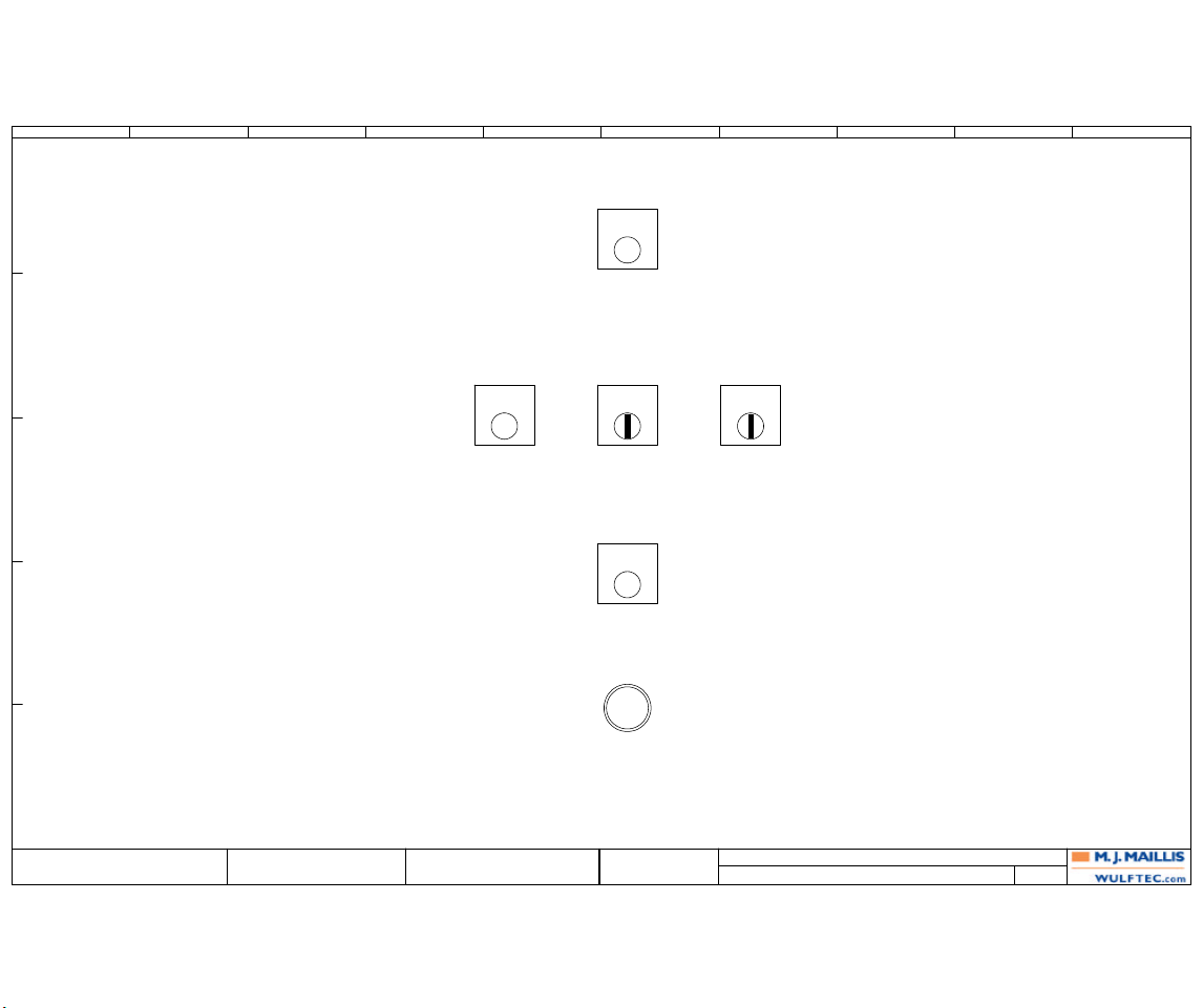
SWITCH BOARD FRONT VIEW
217
WULFTEC MJ MAILLIS
209 WULFTEC
ANDRE BUREAU 6EPAN03622
QUEBEC, CANADA
GUY LOPES
0 11/01/2006 A.B.PRODUCTION
217
WULFTEC M.J. MAILLIS
SMART SERIES WRTA
Revision Date Name
Drawn By:
Verified By:
Page Title:
Dwg. No.: Page:
(206D3)
PB-02
E-STOP
(206C3)
SW-01
CARRIAGE
UP DOWN
(206C3)
SW-02
REINF MANUAL
WRAP ROT
(206D3)
SWL-01
STATUS
POWER
OFF ON
(206B3)
PB-01
START/STOP
(206B3)
PB-03
RESET
E
D
C
B
A
1 2 3 4 5 6 7 8 9 10
Page 85
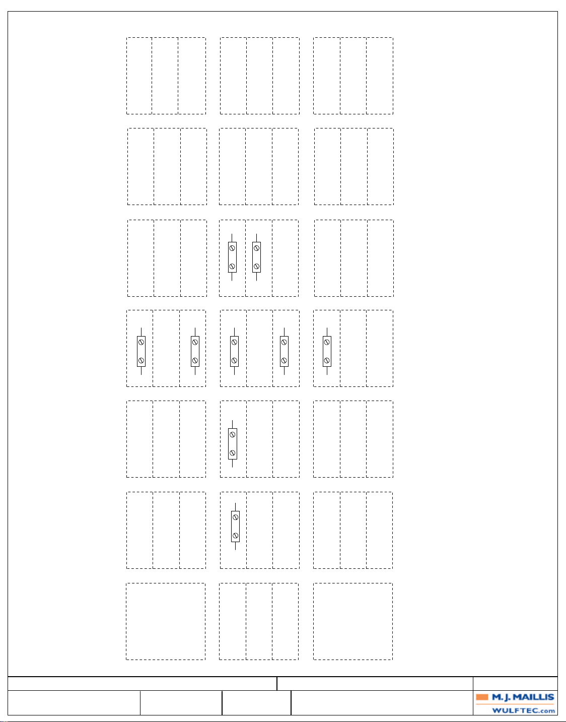
POS-1 POS-3 POS-2
POS-1
POS-3 POS-2 POS-1 POS-3 POS-2
46
7
PLC-01:Q00.0TB-01:7
FU-03:1CB-03:L1
x1
13
SWL-01
SWL-01
STATUS
STATUS
POWER
POWER
OFF ON
OFF ON
x2
14
0V
6
PLC-01:I00.3SW-01:24
13
14
45
SW-01
24V
CARRIAGE
UP DOWN
PLC-01:I00.4SW-02:14
23
24
SW-01:14
44
SW-01
24V
CARRIAGE
UP DOWN
TB-01:10TB-01:2
PLC-01:I00.7SW-02:24
13
14
SW-01:24
40
13
PB-01
14
24V
PB-03:14
TB-02:6TB-02:5
11
12
43
SW-02
WRAP ROT
REINF MANUAL
24V
START/STOP
48
PB-02
E-STOP
47
PLC-02:I08.6PB-03:14
23
24
SW-02:14
42
SW-02
24V
WRAP ROT
REINF MANUAL
PLC-02:I08.3PB-01:14
13
14
SW-02:24
41
PB-03
24V
RESET
Page Title:
Revision
0 PRODUCTION
SWITCH BOARD BACK VIEW
Date
Name
07/14/2008
A.B.
Drawn By: ANDRE BUREAU
Verified By: GUY LOPES
6EPAN03622
WULFTEC M.J. MAILLIS
SMART SERIES WRTA
Dwg. No.:
218
WULFTEC MJ MAILLIS
209 WULFTEC
QUEBEC, CANADA
Page: 218
Page 86
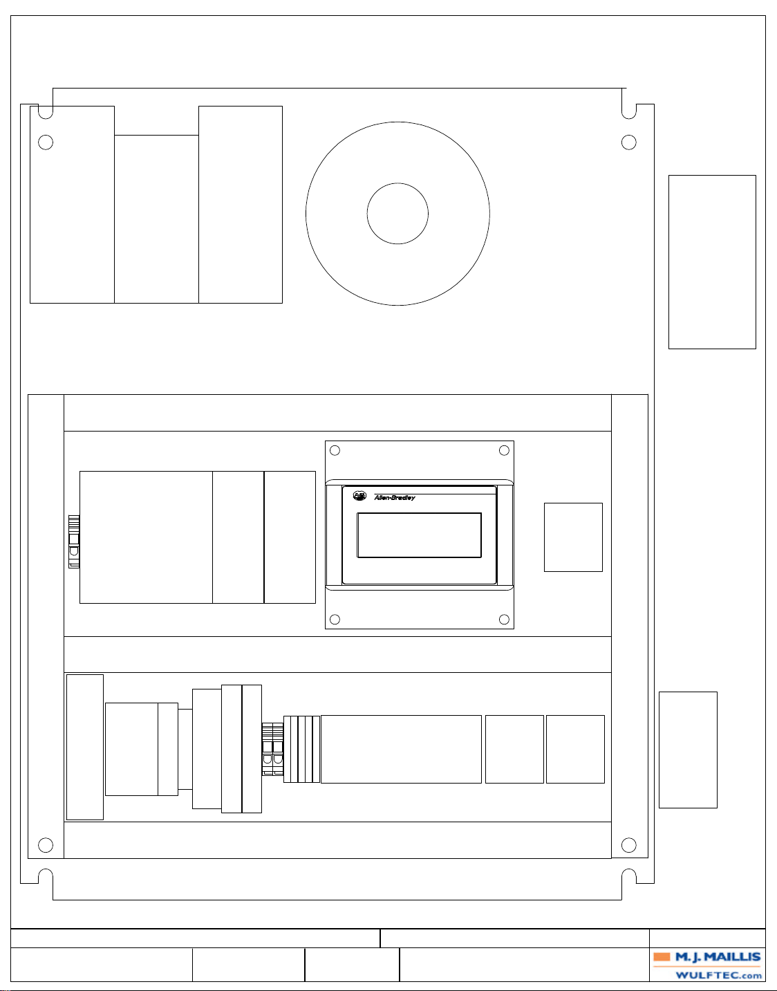
T-1
BR-01 CAN
BE UNDER
VFD-03 OR
ON SIDE
PRE-STRETCH
DRIVE
VFD-01
CARRIAGE
DRIVE
VFD-02
PLC-01
ROTATION
DRIVE
VFD-03
PLC-02
PLC-03
HMI-01
TB-06
MAIN
TRANSFORMERS
TERMINALS
BR-01
Page Title:
Revision
0 PRODUCTION
PWS-01
PANEL LAYOUT
Date
11/01/2006
TD-01
MCR-01
Name
A.B.
CB-01
CR-01
CB-02
CB-03
Drawn By: ANDRE BUREAU
Verified By: GUY LOPES
FU-02
FU-01
FU-03
FU-04
FU-05
6EPAN03622
WULFTEC M.J. MAILLIS
SMART SERIES WRTA
TB-01
DC DISTRIBUTION
Dwg. No.:
219
WULFTEC MJ MAILLIS
209 WULFTEC
QUEBEC, CANADA
TB-02
AC DISTRIBUTION
24 PINS QP16 PINS QP
TB-04
CUT AND WIPE
CONTROL
T-02
Page: 219
Page 87
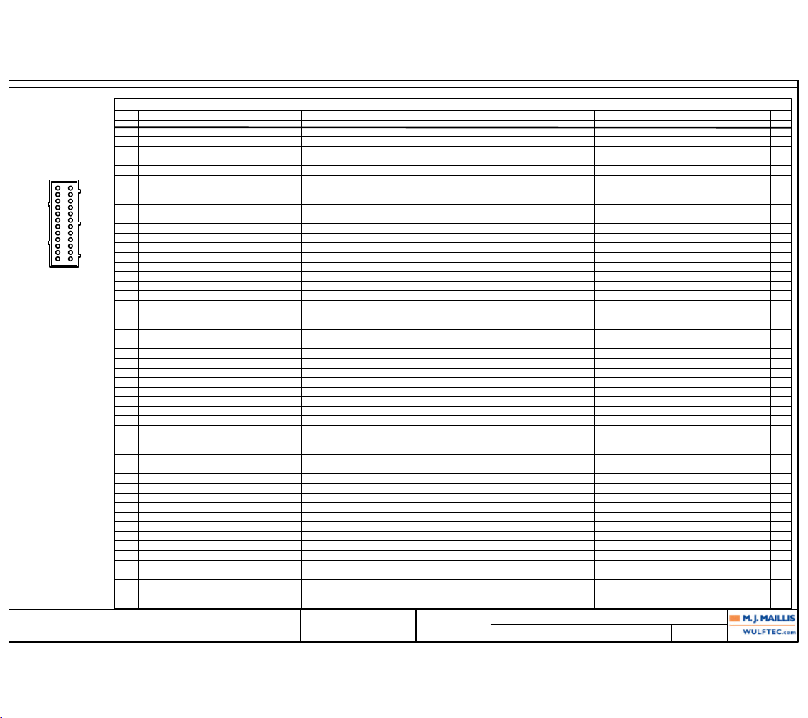
Revision
0 PRODUCTION
Date
11/01/2006
Name
A.B.
Verified By: GUY LOPES
6EPAN03622
WULFTEC M.J. MAILLIS
WULFTEC MJ MAILLIS
209 WULFTEC
QUEBEC, CANADA
Page Title:
Dwg. No.:
QUICK PLUG PIN CHART: QP-01
220
Drawn By: ANDRE BUREAU
Page: 220SMART SERIES WRTA
QUICK PLUG PIN CHART
PLUG:
POLE
TARGET WIRE
FEMALE SIDE
CABLE TARGET WIRE
MALE SIDE
CABLE LAST TARGET
FUNCTION TEXT PAGE
1 TB-01:2 24V :BLU PE-01:BRN 24V PE-01 AUTOHEIGHT (211A3)
2 TB-01:6 0V :BLU/WHT PE-01:BLU PE-01 AUTOHEIGHT (211B3)
3 PLC-01:I00.2 100 :BLU PE-01:WHT PE-01 AUTOHEIGHT (211B3)
4 PLC-01:I00.5 101 :BLU LS-01:12 LS-01 CARRIAGE RAISED (211B3)
5 PLC-01:I00.6 102 :BLU LS-02:12 LS-02 CARRIAGE LOWERED (211C3)
6 VFD-01:10 60 :BLU AS-01:BLK AS-01 FORCE TO LOAD (211C3)
7 PLC-02:I08.4 87 :BLU PS-03:BLK PS-03 COUNT POSITION (210A7)
8 PLC-02:Q08.5 89 :BLU BCN-01:1 BCN-01 WARNING BEACON (210B7)
9 PLC-01:I01.0 88 :BLU PS-01:BLK PS-01 HOME POSITION (210B7)
10 TB-02:5 47 :BLU PE-03:BLK PE-03 ROTARY ARM BUMPER (210C7)
11 TB-01:10 40 :BLU PC-01:14 PC-01 PULL CORD (START/STOP) (210C7)
12
13
14 VFD-01:U CBL-03:BLK MTR-01:T1 MTR-01 PRE-STRETCH MTR (208D6)
15 VFD-01:V CBL-03:WHT MTR-01:T2 MTR-01 PRE-STRETCH MTR (208E6)
16 VFD-01:W CBL-03:RED MTR-01:T3 MTR-01 PRE-STRETCH MTR (208E6)
17 VFD-01:GND CBL-03:GRN MTR-01:G MTR-01 PRE-STRETCH MTR (208E6)
18 VFD-02:U CBL-05:BLK MTR-02:T1 MTR-02 CARRIAGE UP/DWN MTR (209D6)
19 VFD-02:V CBL-05:WHT MTR-02:T2 MTR-02 CARRIAGE UP/DWN MTR (209E6)
20 VFD-02:W CBL-05:RED MTR-02:T3 MTR-02 CARRIAGE UP/DWN MTR (209E6)
21 VFD-02:GND CBL-05:GRN MTR-02:G MTR-02 CARRIAGE UP/DWN MTR (209E6)
22 VFD-03:U CBL-07:BLK MTR-03:T1 MTR-03 ROTATION MTR (210D7)
23 VFD-03:V CBL-07:WHT MTR-03:T2 MTR-03 ROTATION MTR (210E7)
24 VFD-03:W CBL-07:RED MTR-03:T3 MTR-03 ROTATION MTR (210E7)
PE VFD-03:GND CBL-07:GRN MTR-03:G MTR-03 ROTATION MTR (210E7)
16
15
14
13
12
11
10
9
PE
8
7
6
5
4
3
2
1
17
18
19
20
21
22
23
24
QP-01 TO SLIP RING
E
D
C
B
A
1 2 3 4 5 6 7 8 9 10
Page 88
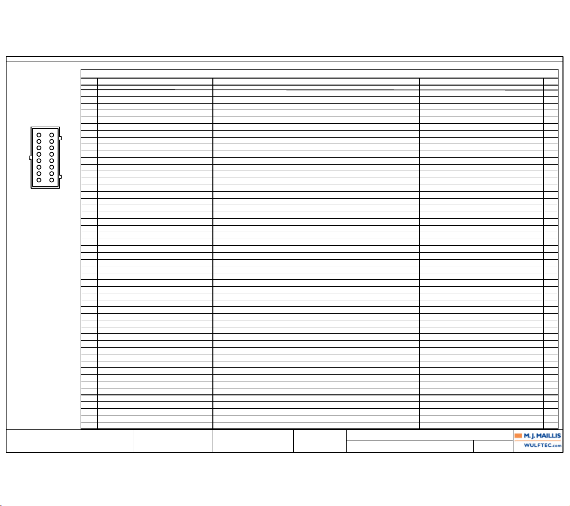
Revision
0 PRODUCTION
Date
11/01/2006
Name
A.B.
Verified By: GUY LOPES
6EPAN03622
WULFTEC M.J. MAILLIS
WULFTEC MJ MAILLIS
209 WULFTEC
QUEBEC, CANADA
Page Title:
Dwg. No.:
QUICK PLUG PIN CHART: QP-02
221
Drawn By: ANDRE BUREAU
Page: 221SMART SERIES WRTA
QUICK PLUG PIN CHART
PLUG:
POLE
TARGET WIRE
FEMALE SIDE
CABLE TARGET WIRE
MALE SIDE
CABLE LAST TARGET
FUNCTION TEXT PAGE
1 TB-01:3 24V :BLU TB-200:1 CBL-16:RED PBL-01 FILM CLAMP OPEN/CLOSE ROTARY ARM AT HOME POSITION (212B2)
2 TB-01:9 0V :BLU/WHT TB-200:5 CBL-16:BLK PBL-01 FILM CLAMP OPEN/CLOSE ROTARY ARM AT HOME POSITION (212B2)
3 TB-02:6 48 :BLU TB-200:8 CBL-16:WHT PB-04 E-STOP (212A2)
4 TD-01:B1 52 :BLU TB-200:9 CBL-16:GRN PB-04 E-STOP (212A8)
5 TB-200:10 CBL-16:ORG 10 (212D8)
6 TB-200:11 CBL-16:BLU 11 (212D8)
7 PLC-02:Q08.4 110 :BLU TB-200:12 CBL-16:WHT/BLK PBL-01 FILM CLAMP OPEN/CLOSE ROTARY ARM AT HOME POSITION (212B8)
8 PLC-02:I08.2 111 :BLU TB-200:13 CBL-16:RED/BLK PBL-01 FILM CLAMP OPEN/CLOSE ROTARY ARM AT HOME POSITION (212B8)
9 PLC-02:I08.0 112 :BLU TB-200:14 CBL-16:GRN/BLK RS-01 PUSH ARM EXTENDED (212B8)
10 PLC-02:I08.1 113 :BLU TB-200:15 CBL-16:ORG/BLK PS-04 PUSH ARM RETRACTED (212C8)
11 PLC-02:Q08.0 114 :BLU TB-200:16 CBL-16:BLU/BLK SOL-01 PUSH ARM (212C8)
12 PLC-02:Q08.1 115 :BLU TB-200:17 CBL-16:BLK/WHT SOL-01 PUSH ARM (212C8)
13 PLC-02:Q08.2 116 :BLU TB-200:18 CBL-16:RED/WHT SOL-02 WIPE ARM (212D8)
14 PLC-02:Q08.3 117 :BLU TB-200:19 CBL-16:GRN/WHT SOL-03 FILM CLAMP (212D8)
15 FU-02:2 23 :BLK TB-200:20 CBL-77:BLK HW-01 HEAT WIRE (204D6)
16 TB-04:4 00 :WHT TB-200:21 CBL-77:WHT HW-01 HEAT WIRE (204D6)
PE TB-04:4 :GRN TB-200:22 :GRN 22 (204D6)
9
10
11
12
13
14
15
16
PE
1
2
3
4
5
6
7
8
QP-02 WRTA CONTROL
E
D
C
B
A
1 2 3 4 5 6 7 8 9 10
Page 89
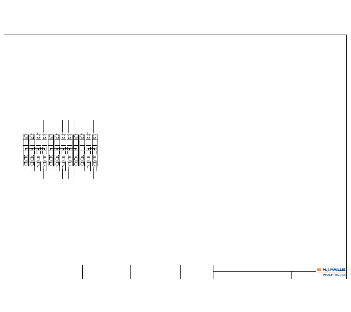
Revision
0 PRODUCTION
Date
11/01/2006
Name
A.B.
Verified By: GUY LOPES
6EPAN03622
WULFTEC M.J. MAILLIS
WULFTEC MJ MAILLIS
209 WULFTEC
QUEBEC, CANADA
Page Title:
Dwg. No.:
TERMINAL DIAGRAM: TB-01
222
Drawn By: ANDRE BUREAU
Page: 222SMART SERIES WRTA
External targets Wiring Internal Target
TERMINAL STRIP:
Wiring
FUNCTION:
Terminal
Location
External Target
Location
Internal Target
Location
24V 24V
(204A4)BLUBLUPLC-01:1L(205C5)
1
FU-01:2(204B5)
24V 24V
(206B3)BLUBLUQP-01:1(211A3)
2
PB-01:14(204B5)
24V 24V
(207A5)BLUBLUQP-02:1(212B2)
3
TD-01:18(204B6)
24V 24V
(206C8)BLUBLUVFD-01:21(208D5)
4
HMI-01:+(204B6)
24V
BLUVFD-01:19(208C5)
0V 0V
(204A3)BLU/WHTBLUPLC-01:1M(205C5)
5
PWS-01:-(204B6)
0V 0V
(211B3)BLU/WHTBLU/WHTVFD-01:28(208C5)
6
QP-01:2(204B7)
0V
BLU/WHTVFD-01:11(208B5)
0V 0V
(206D3)BLU/WHTBLU/WHTVFD-02:9(209C5)
7
SWL-01:x2(204B7)
0V 0V
(207A6)BLU/WHTBLU/WHTVFD-03:28(210C5)
8
MCR-01:A2(204B7)
0V 0V
(206C8)BLU/WHTBLU/WHTQP-02:2(212B2)
9
HMI-01:-(204B8)
40 40
(206B5)BLUBLUPB-01:13(206B3)
10
PLC-01:I00.1(206B4)
40
BLUQP-01:11(210C7)
61 61
(208B5)BLUBLUPLC-01:Q00.7(208B3)
11
VFD-01:7(208B3)
61 61
(209B5)BLUBLUVFD-03:7(210B5)
12
VFD-02:7(208C3)
TB-01 DC DISTRIBUTION
E
D
C
B
A
1 2 3 4 5 6 7 8 9 10
Page 90
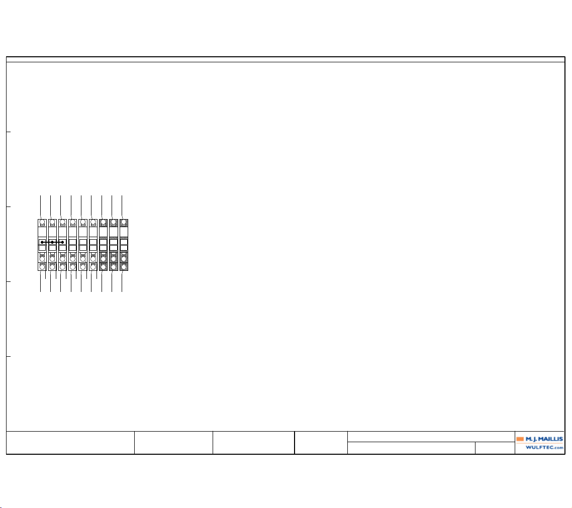
Revision
0 PRODUCTION
Date
11/01/2006
Name
A.B.
Verified By: GUY LOPES
6EPAN03622
WULFTEC M.J. MAILLIS
WULFTEC MJ MAILLIS
209 WULFTEC
QUEBEC, CANADA
Page Title:
Dwg. No.:
TERMINAL DIAGRAM: TB-02
223
Drawn By: ANDRE BUREAU
Page: 223SMART SERIES WRTA
External targets Wiring Internal Target
TERMINAL STRIP:
Wiring
FUNCTION:
Terminal
Location
External Target
Location
Internal Target
Location
0
(203A3)WHTCBL-01:WHTN:_0(203E2)
1
TB-06:1(203D2)
0
WHTPLC-01:N(205C3)
2
(203B7)
0
WHTPWS-01:N(204A3)
3
(203B7)
0
WHTTB-04:1(204D3)
1
(203C1)BLKCBL-01:BLKL1:_0(203E1)
4
CB-01:L1(203D1)
47 47
(206D3)BLUBLUQP-01:10(210C7)
5
PB-02:12(206D2)
48 48
(206D3)BLUBLUQP-02:3(212A2)
6
PB-02:11(206D4)
CBL-01:GRNGND:_0(203E2)
7
(203D2)
(204A3)GRN
8
PWS-01:-(204B5)
GRNHMI-01:PE(206C8)
9
(206C7)
TB-02 AC DISTRIBUTION
E
D
C
B
A
1 2 3 4 5 6 7 8 9 10
Page 91
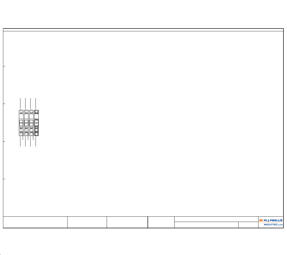
Revision Date Name
Verified By:
6EPAN03622
WULFTEC M.J. MAILLIS
WULFTEC MJ MAILLIS
209 WULFTEC
QUEBEC, CANADA
Page Title:
Dwg. No.:
TERMINAL DIAGRAM: TB-04
224
Drawn By: ANDRE BUREAU
Page: 224SMART SERIES WRTA
External targets Wiring Internal Target
TERMINAL STRIP:
Wiring
FUNCTION:
Terminal
Location
External Target
Location
Internal Target
Location
0 0
(204D4)WHTWHTTB-02:3(203B7)
1
T-02:H4(204D3)
21 21
(204D4)BLKREDCR-01:11(204D2)
2
T-02:H1(204D3)
22 22
(204D4)REDBLKFU-02:1(204D5)
3
T-02:X1(204D5)
00 00
(204D4)YELWHTQP-02:16(204D6)
4
T-02:X4(204D5)
GRNQP-02:PE(204D6)
TB-04 CUT AND WIPE CONTROL
E
D
C
B
A
1 2 3 4 5 6 7 8 9 10
Page 92
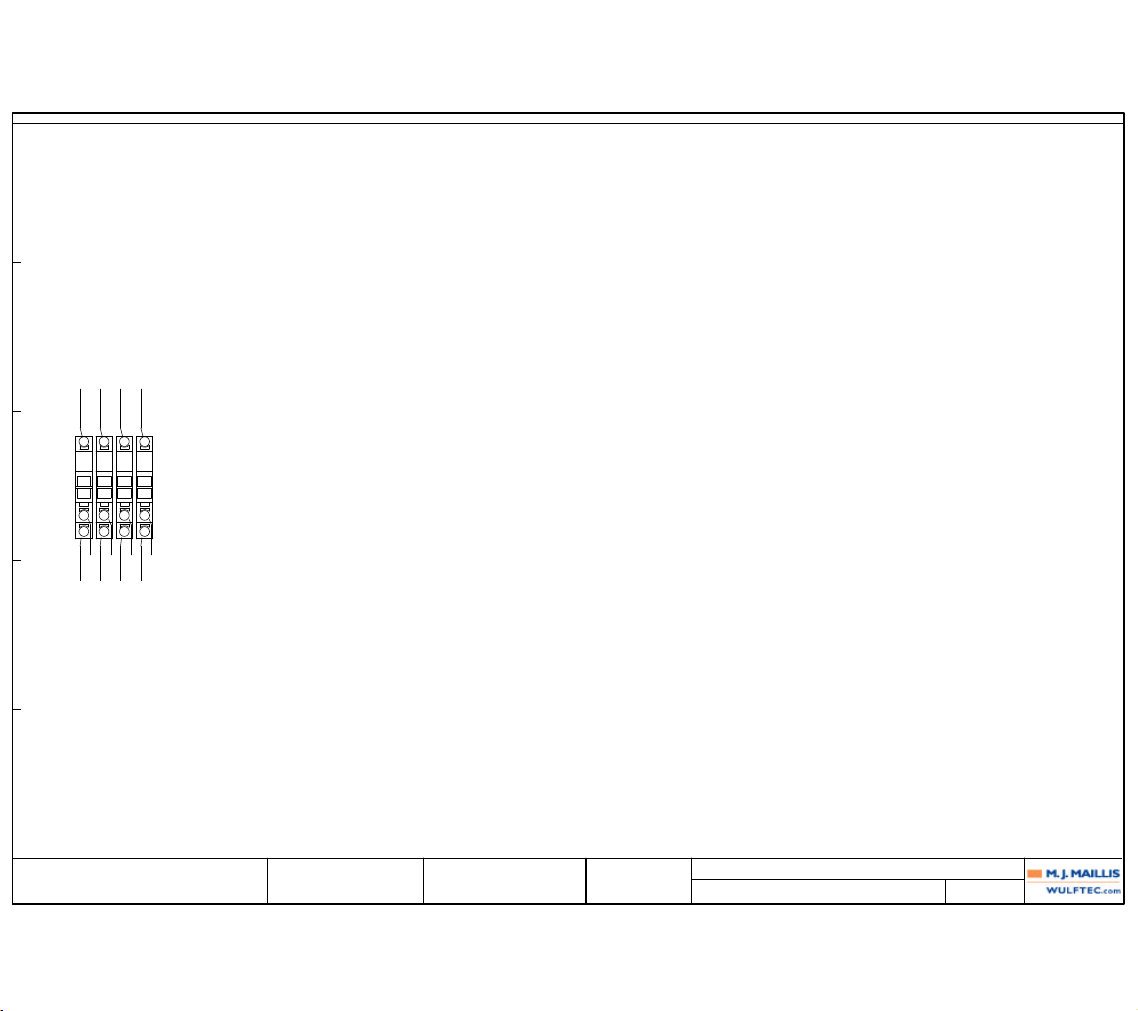
Revision Date Name
Verified By:
6EPAN03622
WULFTEC M.J. MAILLIS
WULFTEC MJ MAILLIS
209 WULFTEC
QUEBEC, CANADA
Page Title:
Dwg. No.:
TERMINAL DIAGRAM: TB-06
225
Drawn By: ANDRE BUREAU
Page: 225SMART SERIES WRTA
External targets Wiring Internal Target
TERMINAL STRIP:
Wiring
FUNCTION:
Terminal
Location
External Target
Location
Internal Target
Location
0 0
(203A3)WHTWHTTB-02:1(203D2)
1
T-01:H1(203A3)
0 0
(203A3)WHTWHTVFD-01:L2(208E5)
2
T-01:X2(H1)(203A4)
2 2
(203A3)BLKBLKCB-01:T1(203C1)
3
T-01:H2(203A3)
2
BLKCB-03:T1(203B5)
3 3
(203A3)BRNBLKCB-02:T1(203A5)
4
T-01:X1(203A4)
TB-06 MAIN TRANSFORMERS TERMINALS
E
D
C
B
A
1 2 3 4 5 6 7 8 9 10
Page 93

Revision Date Name
Verified By:
6EPAN03622
WULFTEC M.J. MAILLIS
WULFTEC MJ MAILLIS
209 WULFTEC
QUEBEC, CANADA
Page Title:
Dwg. No.:
TERMINAL DIAGRAM: TB-200
226
Drawn By: ANDRE BUREAU
Page: 226SMART SERIES WRTA
External targets Wiring Internal Target
TERMINAL STRIP:
Wiring
FUNCTION:
Terminal
Location
External Target
Location
Internal Target
Location
(212B2)CBL-16:REDCBL-17:REDPBL-01:13(212B5)
1
QP-02:1(212B3)
RS-01:BRNRS-01:BRN(212B5)
2
(212B3)
CBL-18:BRNPS-04:BRN(212C5)
3
(212C3)4(212C3)
(212B2)CBL-16:BLKCBL-17:BLKPBL-01:X2(212B5)
5
QP-02:2(212B3)
CBL-18:BLUPS-04:BLU(212C5)
6
(212C3)
CBL-19:ORG/REDSOL-01:ORG/RED(212C5)
7
(212C3)
(212A2)CBL-16:WHTCBL-17:WHTPB-04:12(212A5)
8
QP-02:3(212A3)
(212A8)CBL-16:GRNCBL-17:GRNPB-04:11(212A5)
9
QP-02:4(212A7)
(212D8)CBL-16:ORG
10
QP-02:5(212D7)
(212D8)CBL-16:BLU
11
QP-02:6(212D7)
(212B8)CBL-16:WHT/BLKCBL-17:ORGPBL-01:X1(212B5)
12
QP-02:7(212B7)
(212B8)CBL-16:RED/BLKCBL-17:BLUPBL-01:14(212B5)
13
QP-02:8(212B7)
(212B8)CBL-16:GRN/BLKRS-01:BLURS-01:BLU(212B5)
14
QP-02:9(212B7)
(212C8)CBL-16:ORG/BLKCBL-18:BLKPS-04:BLK(212C5)
15
QP-02:10(212C7)
(212C8)CBL-16:BLU/BLKCBL-19:BLKSOL-01:BLK(212C5)
16
QP-02:11(212C7)
(212C8)CBL-16:BLK/WHTCBL-19:YEL/BLKSOL-01:YEL/BLK(212C5)
17
QP-02:12(212C7)
(212D8)CBL-16:RED/WHTCBL-19:BRNSOL-02:BRN(212D5)
18
QP-02:13(212D7)
(212D8)CBL-16:GRN/WHTCBL-19:REDSOL-03:RED(212D5)
19
QP-02:14(212D7)
(204D6)CBL-77:BLKCBL-78:BLKHW-01:_0(204D8)
20
QP-02:15(204D7)
(204D6)CBL-77:WHTCBL-78:WHTHW-01:_1(204D8)
21
QP-02:16(204D7)
(204D6)GRN
22
QP-02:PE(204D7)
TB-200 WRAP ZONE JB
E
D
C
B
A
1 2 3 4 5 6 7 8 9 10
Page 94
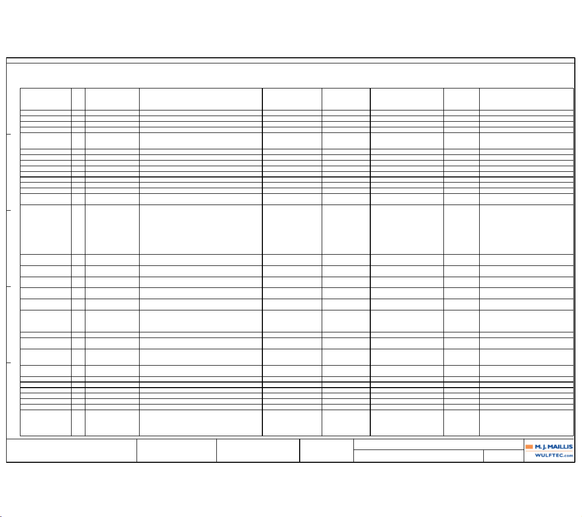
Revision
0 PRODUCTION
Date
11/01/2006
Name
A.B.
Verified By: GUY LOPES
6EPAN03622
WULFTEC M.J. MAILLIS
WULFTEC MJ MAILLIS
209 WULFTEC
QUEBEC, CANADA
Page Title:
Dwg. No.:
DEVICE LIST: (BR-01 - SW-01)
227
Drawn By: ANDRE BUREAU
Page: 227SMART SERIES WRTA
DT
QTY
L
DESCRIPTION
MODEL NUMBERMANUFACTURER
PART NUMBER
PAGE FUNCTION TEXT
LOCATION
6EPAN03622
DEVICE LIST FOR PROJECT:
BR-01 1 0EDRV00122 BRAKE RES. VECTOR MM440 1H 230VAC PANEL SIEMENS 6SE64004BC050AA1 (210E4)
CB-01 1 0EFUS00307 BREAKER 15A 1 POLE MAIN PANEL AB 1489-A1C150 (203C1)
CB-02 1 0EFUS00361 BREAKER 10A 1 POLE PANEL AB 1489-A1C100 (203A5)
CB-03 1 0EFUS00361 BREAKER 10A 1 POLE PANEL AB 1489-A1C100 (203B5)
CBL-01 1 0ECAB00069 3C14 SJOW 30FT EXT. PANEL (203D2) POWER FEEDER
1 0ECNT00077 CABLE GLAND CONN. 1/2" NPT 52112
1 0ECNT00196 LOCK NUT 1/2" STEEL 1704
CBL-02 PANEL (208A4)
CBL-03 2 0ECAB00207 4C16 PVC SHLD PANEL 316-023-1604-FR (208D6) PRESTRETCH MOTOR
CBL-04 1 0ECAB00244 2C18 PVC SHLD (DC) PANEL CAB18/1PRSHFT4 (209A4)
CBL-05 2 0ECAB00207 4C16 PVC SHLD PANEL 316-023-1604-FR (209D6) CARRIAGE MOTOR
CBL-06 1 0ECAB00244 2C18 PVC SHLD (DC) PANEL CAB18/1PRSHFT4 (210A4)
CBL-07 2 0ECAB00207 4C16 PVC SHLD PANEL 316-023-1604-FR (210D6) ROTATION MOTOR
CBL-30 1 0ECAB00244 2C18 PVC SHLD (DC) PANEL CAB18/1PRSHFT4 (208A4)
CBL-80 1 0ECAB00458 1.5' ETHERNET CABLE PANEL (206C9)
CR-01 1 0ERLY00167 RELAY HEAD SPDT 24VDC COIL WITH LED PANEL AB 700-HK36Z244 (207B6) HEAT WIRE
1 0ERLY00166 BASE RELAY FOR 700-HK AB 700-HN121
ENC-01 6 0ECNT00075 COVER DUCT 1" PANEL ENTRELEC C1LG6 PANDUIT (203E1)
6 0ECNT00127 WIRE DUCT 1" X 3" PANDUIT F1X3LG6
1 0ELAB00305 WALMART SWITCH BRD EXTERNE
1 0ELAB00306 WALMART SWITCH BRD INTERNE
2 5MBRK01846 ENCLOSURE SUPPORT BRACKET
1 0EENC00107 KEYLOCKABLE 1/4 TURN LOCK EUROBEX 880SCQ4K
1 0EENC00348 NEMA 4/12 BLUE 30X24X08 EUROBEX W511090089
4 0ECNT00236 SPACER GREY PVC 2" X 3/8 OD MISC. SS816L
4 0MFST00562 MACHINE SCREW ZC #8-32 X 2 1/2 MS408025
FU-01 1 0EFUS00331 FUSE HOLDER FOR GMA PANEL WAGO 2002-1611 (204A4)
1 0EFUS00041 FUSE GMA 2A BUSS GMA2 OR EQ.
FU-02 1 0EFUS00105 FUSE GMA 15A PANEL BUSS GMA15 OR EQ. (204D5)
1 0EFUS00331 FUSE HOLDER FOR GMA WAGO 2002-1611
FU-03 1 0EFUS00331 FUSE HOLDER FOR GMA PANEL WAGO 2002-1611 (203B8)
1 0EFUS00041 FUSE GMA 2A BUSSMANN GMA2 OR EQ.
FU-04 1 0EFUS00331 FUSE HOLDER FOR GMA PANEL WAGO 2002-1611 (203B8)
1 0EFUS00041 FUSE GMA 2A BUSSMANN GMA2 OR EQ.
FU-05 1 0EFUS00331 FUSE HOLDER FOR GMA PANEL WAGO 2002-1611 (203B8)
1 0EFUS00408 FUSE GMA 5A SLOW BLOW BUSSMANN S506-5R
HMI-01 1 0EPLC00643 HMI KP300 BASIC MONO 4" TOUCH SCREEN DOOR SIEMENS 6AV6647-0AH11-3AX0 (206C8)
4 0ECNT00236 SPACER GREY PVC 2" X 3/8 OD MISC. SS816L
4 0MFST00562 MACHINE SCREW ZC #8-32 X 2 1/2 MS408025
1 5MBRK02731 TK-300 INTERNAL PANEL SUPPORT WULFTEC 5MBRK02731
MCR-01 1 0ERLY00110 CONTACTOR 9A 24VDC COIL 1NO PANEL AB 100-C09ZJ10 (207A6) MAIN CONTACTOR
PB-01 1 0ESWT00331 800F PB FLUSH GREEN DOOR AB 800FP-F3 (206B3) START/STOP
1 0ESWT00581 800F CAGE CLAMP BASE 3 WITH CONTACT 1NO AB 800F-PQ10
PB-02 1 0ESWT00339 800F E-STOP PUSH/TWIST (40MM HEAD) DOOR AB 800FP-MT44 (206D3) E-STOP
1 0ELAB00023 800F E-STOP LABEL EN,FR,SP AB 800F-15YB112
1 0ESWT00582 800F CAGE CLAMP BASE 3 WITH CONTACT 1NC AB 800F-PQ01
PB-03 1 0ESWT00329 800F PB FLUSH BLACK DOOR AB 800FP-F2 (206B3) RESET
1 0ESWT00581 800F CAGE CLAMP BASE 3 WITH CONTACT 1NO AB 800F-PQ10
PLC-01 1 0EPLC00629 S7-1200 CPU 1214C AC/DC/RLY PANEL SIEMENS 6ES7 214-1BD23-0XB0 (205D3)
PLC-02 1 0EPLC00630 S7-1200 SM 1223 8 IN 8 OUT DC/RLY PANEL SIEMENS 6ES7-223-1PH32-0XB0 (205D5)
PLC-03 1 0EPLC00632 S7-1200 SM 1232 4 ANALOG OUTPUT PANEL SIEMENS 6ES7-232-4HD32-0XB0 (205D8)
PWS-01 1 0EPWR00327 POWER SUPPLY 24VDC/2.5A 60W PANEL WIELAND (204A3) POWER SUPPLY
QP-01 1 0ECNT00341 QUICK PLUG KIT 24 PINS PANEL CONTACT CRAS000005 TO SLIP RING
QP-02 1 0ECNT00340 16 POLES QUICK PLUG KIT PANEL WEIDMULLER 7940032772 WRTA CONTROL
SW-01 1 0ESWT00337 800F 3POS SPR RTN SWITCH BLACK DOOR AB 800FP-SB32 (206C3) CARRIAGE UP DOWN
1 0ESWT00581 800F CAGE CLAMP BASE 3 WITH CONTACT 1NO AB 800F-PQ10
1 0ESWT00583 800F CAGE CLAMP CONTACT 1NO AB 800F-Q10
E
D
C
B
A
1 2 3 4 5 6 7 8 9 10
Page 95
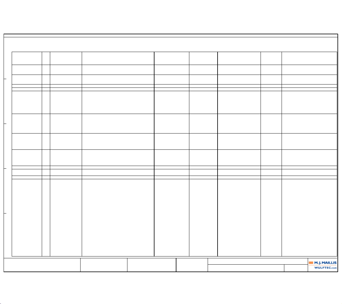
Revision
0 PRODUCTION
Date
11/01/2006
Name
A.B.
Verified By: GUY LOPES
6EPAN03622
WULFTEC M.J. MAILLIS
WULFTEC MJ MAILLIS
209 WULFTEC
QUEBEC, CANADA
Page Title:
Dwg. No.:
DEVICE LIST: (SW-02 - VFD-03)
228
Drawn By: ANDRE BUREAU
Page: 228SMART SERIES WRTA
DT
QTY
L
DESCRIPTION
MODEL NUMBERMANUFACTURER
PART NUMBER
PAGE FUNCTION TEXT
LOCATION
6EPAN03622
DEVICE LIST FOR PROJECT:
SW-02 1 0ESWT00337 800F 3POS SPR RTN SWITCH BLACK DOOR AB 800FP-SB32 (206C3) REINF MANUAL WRAP ROT
1 0ESWT00581 800F CAGE CLAMP BASE 3 WITH CONTACT 1NO AB 800F-PQ10
1 0ESWT00583 800F CAGE CLAMP CONTACT 1NO AB 800F-Q10
SWL-01 1 0ESWT00334 800F 2POS MAINT. SWITCH ILL. GREEN DOOR AB 800FP-LSM23 (206D3) STATUS POWER OFF ON
1 0ESWT00581 800F CAGE CLAMP BASE 3 WITH CONTACT 1NO AB 800F-PQ10
1 0ESWT00591 800F CAGE CLAMP LED GREEN 24VDC AB 800F-Q3G
T-01 1 0EPWR00305 XFO 2KVA TOROIDAL 120-240 OPEN PANEL TRANSFAB (203A3)
T-02 1 0EPWR00259 XFO 250VA TOROIDAL 120-24 OPEN PANEL DELTA (204D4) HEAT WIRE
TB-01 1 0ETRM00187 CLAMP TERMINAL BLOCK END STOPPER PANEL WAGO 249-116 DC DISTRIBUTION
1 0ETRM00199 CLAMP TERMINAL BLOCK 3 WIRES END PLATE WAGO 2002-1391
1 0ETRM00201 CLAMP TERMINAL BLOCK JUMPER 10 POLES WAGO 2002-410
1 INTERNAL USE WULFTEC INTERNAL USE
2 0ETRM00188 CLAMP TERMINAL BLOCK JUMPER 2 POLES WAGO 2002-402
1 0ETRM00189 CLAMP TERMINAL BLOCK JUMPER 3 POLES WAGO 2002-403
12 0ETRM00198 CLAMP TERMINAL BLOCK 3 WIRES WAGO 2002-1301
TB-02 1 0ETRM00187 CLAMP TERMINAL BLOCK END STOPPER PANEL WAGO 249-116 AC DISTRIBUTION
1 0ETRM00199 CLAMP TERMINAL BLOCK 3 WIRES END PLATE WAGO 2002-1391
1 INTERNAL USE WULFTEC INTERNAL USE
1 0ETRM00189 CLAMP TERMINAL BLOCK JUMPER 3 POLES WAGO 2002-403
6 0ETRM00198 CLAMP TERMINAL BLOCK 3 WIRES WAGO 2002-1301
3 0ETRM00200 CLAMP TERMINAL BLOCK 3 WIRES GROUND WAGO 2002-1307
TB-04 1 0ETRM00187 CLAMP TERMINAL BLOCK END STOPPER PANEL WAGO 249-116 CUT AND WIPE CONTROL
1 0ETRM00199 CLAMP TERMINAL BLOCK 3 WIRES END PLATE WAGO 2002-1391
1 INTERNAL USE WULFTEC INTERNAL USE
3 0ETRM00198 CLAMP TERMINAL BLOCK 3 WIRES WAGO 2002-1301
1 0ETRM00200 CLAMP TERMINAL BLOCK 3 WIRES GROUND WAGO 2002-1307
TB-06 1 0ETRM00187 CLAMP TERMINAL BLOCK END STOPPER PANEL WAGO 249-116 MAIN TRANSFORMERS TERMINALS
1 0ETRM00188 CLAMP TERMINAL BLOCK JUMPER 2 POLES WAGO 2002-402
1 0ETRM00199 CLAMP TERMINAL BLOCK 3 WIRES END PLATE WAGO 2002-1391
1 INTERNAL USE WULFTEC INTERNAL USE
4 0ETRM00198 CLAMP TERMINAL BLOCK 3 WIRES WAGO 2002-1301
TD-01 1 0ERLY00108 MULTI-FUNCTION RELAY PANEL AB 700-FEM3TU23 (207C6) QUICK STOP TIMER
VFD-01 1 0EDRV00107 KEYPAD MM420/MM440 (BASIC) PANEL SIEMENS 6SE64000BP000AA0 (208E5) PRE-STRETCH DRIVE
1 0EDRV00114 AC DRV MM440 1 HP 230VAC VECTOR SIEMENS 6SE64402UC175AA0
VFD-02 1 0EDRV00106 AC DRV MM420 1 HP 230VAC PANEL SIEMENS 6SE64202UC175AA0 (209E5) CARRIAGE DRIVE
VFD-03 1 0EDRV00114 AC DRV MM440 1 HP 230VAC VECTOR PANEL SIEMENS 6SE64402UC175AA0 (210E5) ROTATION DRIVE
E
D
C
B
A
1 2 3 4 5 6 7 8 9 10
Page 96
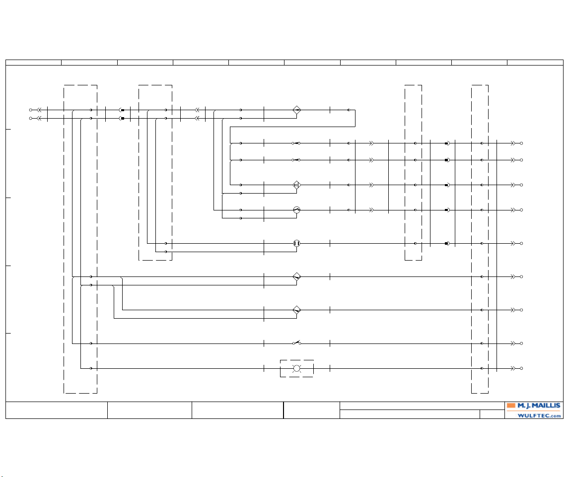
ROTARY ARM CONTROLS
400
WULFTEC MJ MAILLIS
209 WULFTEC
ANDRÉ BUREAU 6ESLR00107
QUEBEC, CANADA
GUY LOPES
1 10/27/2006 A.B.AS BUILT
400
WULFTEC MJ MAILLIS
MODULAR WRAPPER
Revision Date Name
Drawn By:
Verified By:
Page Title:
Dwg. No.: Page:
QP-01
11
CBL-400
(400B9)
19C18
PVC SHLD
RED
BLK
22
FRAME
JB-100
TB-100 1
SLR-01A
(400B9)
RED
BLK
4
2
5
SLR-0122SLR-01B
(400B8)
RED
BLK
ROTARY ARM
JB-101
TB-101 1
33
TB-101 3
2
4
CBL-402
BLU
BRN
CBL-403
BLU
BRN
ROTARY ARM BUMPER
PE-02
BRN BLK
BLU
CBL-402
BLK
PS-01
ROTARY ARM
HOME POSITION
BRN BLK
BLU
CBL-403
BLK
ROTARY ARM
JB-101
TB-101 5
6
7
8
9
SLR-01B
(400A3)
RED/BLK
BLU
GRN
WHT
ORG
SLR-01
44
55
SLR-01A
(400A2)
RED/BLK
BLU
GRN
WHT
ORG
FRAME
JB-100
7
TB-100
8
66
77
9
10
99
11
12
CBL-400
(400A1)
BLU/BLK
GRN/BLK
WHT/BLK
ORG/BLK
RED/BLK
BLU
ORG
GRN
WHT
99
66
QP-01
44
55
33
CBL-401
GRY
BLK
PNK
WHT
1010
CBL-401
(400B7)
6C24
EUROFAST
BLU
BRN
CBL-410
BLU
BRN
PS-03
ROTARY ARM
COUNT POSITION
BRN BLK
BLU
CBL-410
BLK
77
13
CBL-412
4C18
PVC SHLD
BLK
CBL-411
2C18
PVC SHLD (DC)
RED
FRAME
JB-103
BCN-01
0 1
PC-01
PULL CORD (START/STOP)
13 14
CBL-412
WHT
CBL-411
BLK
3
6
14
15
CON-01
6 BRN6 BRN
2 BLU2 BLU
BRN
TB-102 1
4
8
9
2
5
3
TB-102 6
PCBL-04
4C22
MICRO QD
BRN
WHT
PCBL-01
2C18
PVC SHLD (DC)
RED
LS-01
CARRIAGE RAISED
11 12
PCBL-02
2C18
PVC SHLD (DC)
RED
AS-01
BLU
RED
PCBL-03
4C22
MICRO QD
BLU
BRN
LS-02
CARRIAGE LOWERED
11 12
PS-02
GATE DETECTION
BRN BLK
BLU
PCBL-04
BLK
PCBL-01
BLK
AS-01
FORCE TO LOAD
0-10 V
BRN BLK
BLU
AUTOHEIGHT
DARK LOAD DS-60
PE-01
BRN BLK
BLU
PCBL-02
BLK
AS-01
BLK
PCBL-03
BLK
7
10
GRY
BLK
PNK
WHT
11
13
12
CON-01
5 PNK5 PNK
3 BLK3 BLK
1 WHT1 WHT
4 GRY4 GRY
24VDC
0VDC
88
1111
CARRIAGE
RAISED
CARRIAGE
LOWERED
ANALOG
AUTOHEIGHT
BUMPER
HOME
COUNT
PULL-CORD
BEACON
E
D
C
B
A
1 2 3 4 5 6 7 8 9 10
Page 97
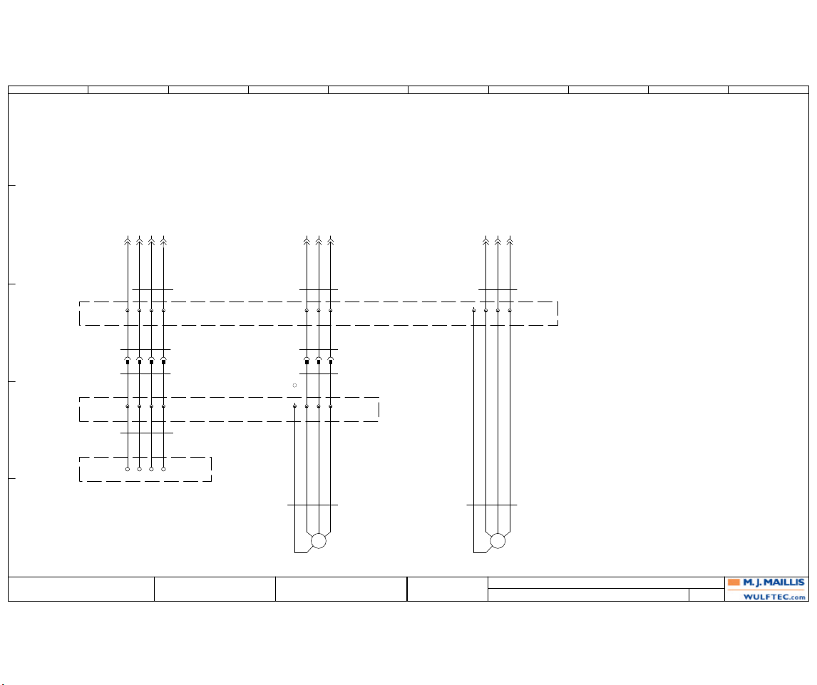
POWER
401
WULFTEC MJ MAILLIS
209 WULFTEC
ANDRÉ BUREAU 6ESLR00107
QUEBEC, CANADA
GUY LOPES
1 10/27/2006 A.B.AS BUILT
401
WULFTEC MJ MAILLIS
MODULAR WRAPPER
Revision Date Name
Drawn By:
Verified By:
Page Title:
Dwg. No.: Page:
15151414 1616 23232222 2424
QP-01
PEPE 1818 1919 2020
FRAME
JB-100
ROTARY ARM
JB-101
CARRIAGE
26TB-100
CBL-404
3C16
PVC
BLK WHT RED
16
17 18
SLR-02A
GRN BLK WHT RED
SLR-02B
GRN BLK WHT RED
CBL-405
4C18
MINI QD
GRN BLK WHT RED
SLR-01
2020
16TB-101
1212101313111414
12
CBL-406
3C16
PVC
BLK WHT RED
19
20 21
17TB-101
SLR-03A
BLK WHT RED
SLR-03B
BLK WHT RED
SLR-01
1515131616141717
15
CBL-407
4C18
MINI QD
GRN BLK WHT RED
MTR-02
CARRIAGE MOTOR
230V, 0.5 TO 1HP
3Ph
M
T1 T2 T3
G
25TB-100
CBL-408
3C16
PVC
BLK WHT RED
22
23 24
CBL-409
4C18
MINI QD
GRN BLK WHT RED
MTR-03
ROTATION MOTOR
230V, 0.5 TO 1HP
3Ph
M
T2 T1 T3
G
PAGE 300
MOTOR
PRESTRETCH
PAGE 200 +
CONTROL
PANEL
PAGE 200 +
CONTROL
PANEL
PAGE 200 +
CONTROL
PANEL
1'' LIQUID TIGHT
27' LONG
CBL-400 30' : 0ECAB00030
CBL-401 180'' : 0ECAB00268
CBL-402 10' : 0ECAB00045
CBL-403 78'' : 0ECAB00213
CBL-404 30' : 0ECAB00238
CBL-405 180'' : 0ECAB00269
CBL-406 30' : 0ECAB00238
CBL-407 48'' : 0ECAB00269
CBL-408 30' : 0ECAB00238
CBL-409 48'' : 0ECAB00269
CBL-410 78'' : 0ECAB00213
CBL-411 40' : 0ECAB00244
CBL-412 84'' : 0ECAB00023
E
D
C
B
A
1 2 3 4 5 6 7 8 9 10
Page 98
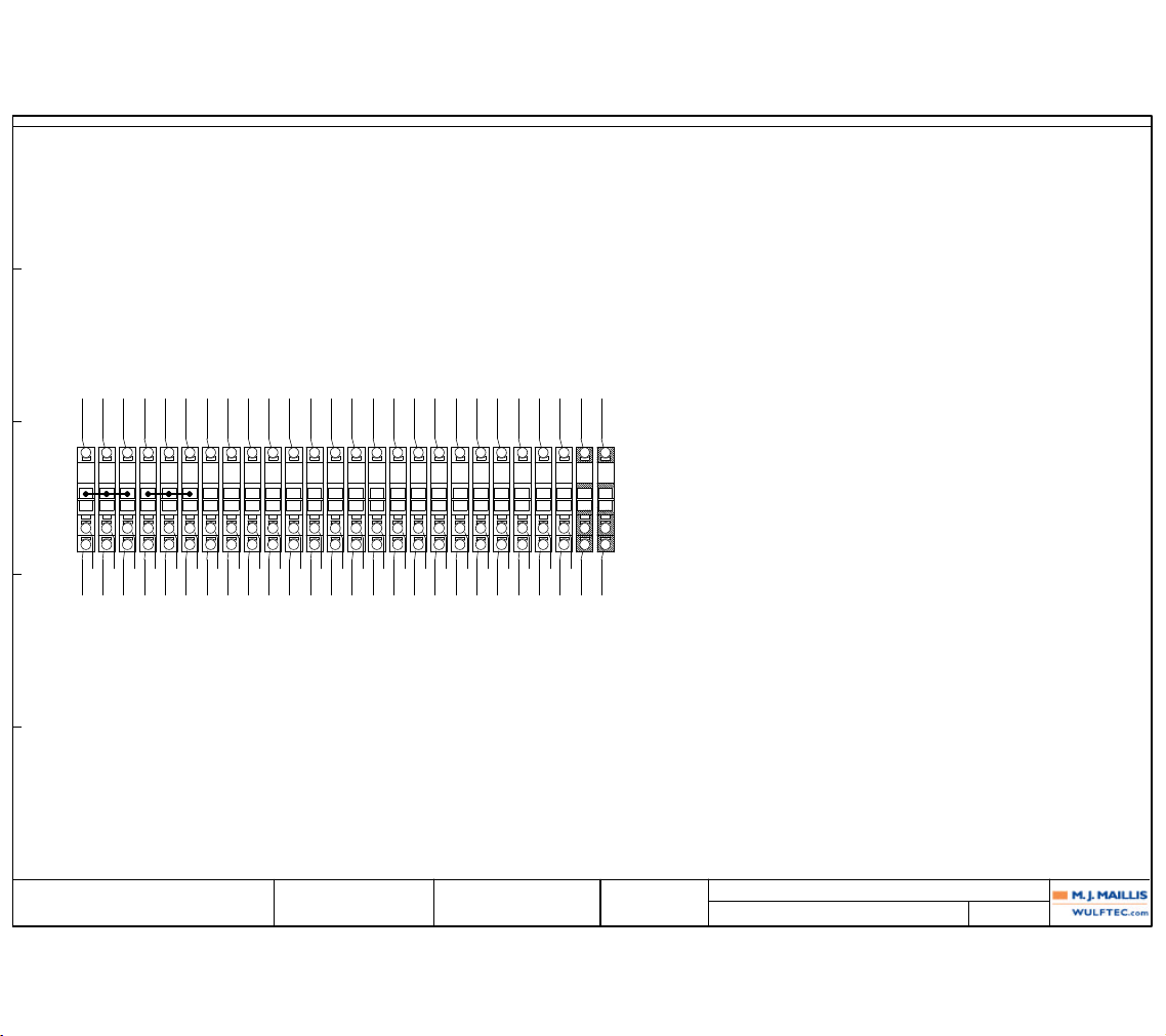
Revision
1 AS BUILT
Date
10/27/2006
Name
A.B.
Verified By: GUY LOPES
6ESLR00107
WULFTEC MJ MAILLIS
WULFTEC MJ MAILLIS
209 WULFTEC
QUEBEC, CANADA
Page Title:
Dwg. No.:
TERMINAL DIAGRAM: TB-100
402
Drawn By: ANDRÉ BUREAU
Page: 402MODULAR WRAPPER
External targets Wiring Internal Target
TERMINAL STRIP:
Wiring
FUNCTION:
Terminal
Location
External Target
Location
Internal Target
Location
(400A1)CBL-400:REDSLR-01A:REDSLR-01:2(400A3)
1
QP-01:1(400A2)
CBL-403:BRNPS-01:BRN(400D6)
2
(400D2)
CBL-410:BRNPS-03:BRN(400D6)
CBL-411:REDPC-01:13(400E6)
3
(400E2)
(400A1)CBL-400:BLKSLR-01A:BLKSLR-01:3(400A3)
4
QP-01:2(400A2)
CBL-403:BLUPS-01:BLU(400D6)
5
(400D2)
CBL-410:BLUPS-03:BLU(400D6)
CBL-412:BLKBCN-01:0(400E6)
6
(400E2)
(400B10)CBL-400:WHTSLR-01A:WHTSLR-01:4(400B8)
7
QP-01:4(400B9)
(400B10)CBL-400:GRNSLR-01A:GRNSLR-01:5(400B8)
8
QP-01:5(400B9)
(400B10)CBL-400:ORGSLR-01A:ORGSLR-01:6(400B8)
9
QP-01:6(400B9)
(400C10)CBL-400:BLUSLR-01A:BLUSLR-01:7(400C8)
10
QP-01:3(400C9)
(400C10)CBL-400:RED/BLKSLR-01A:RED/BLKSLR-01:9(400C8)
11
QP-01:10(400C9)
(400D10)CBL-400:ORG/BLKCBL-403:BLKPS-01:BLK(400D6)
12
QP-01:9(400D9)
(400D10)CBL-400:WHT/BLKCBL-410:BLKPS-03:BLK(400D6)
13
QP-01:7(400D9)
(400E10)CBL-400:GRN/BLKCBL-411:BLKPC-01:14(400E6)
14
QP-01:11(400E9)
(400E10)CBL-400:BLU/BLKCBL-412:WHTBCN-01:1(400E6)
15
QP-01:8(400E9)
(401B2)CBL-404:BLKSLR-02A:BLKSLR-01:12(401C2)
16
QP-01:14(401C2)
(401B2)CBL-404:WHTSLR-02A:WHTSLR-01:13(401C2)
17
QP-01:15(401C2)
(401B2)CBL-404:REDSLR-02A:REDSLR-01:14(401C2)
18
QP-01:16(401C2)
(401B4)CBL-406:BLKSLR-03A:BLKSLR-01:15(401C4)
19
QP-01:18(401C4)
(401B4)CBL-406:WHTSLR-03A:WHTSLR-01:16(401C4)
20
QP-01:19(401C4)
(401B5)CBL-406:REDSLR-03A:REDSLR-01:17(401C5)
21
QP-01:20(401C5)
(401B6)CBL-408:BLKCBL-409:BLKMTR-03:T2(401E7)
22
QP-01:22(401C6)
(401B7)CBL-408:WHTCBL-409:WHTMTR-03:T1(401E7)
23
QP-01:23(401C7)
(401B7)CBL-408:REDCBL-409:REDMTR-03:T3(401E7)
24
QP-01:24(401C7)
CBL-409:GRNMTR-03:G(401E7)
25
(401C6)
(401B2)SLR-02A:GRNSLR-01:20(401C2)
26
QP-01:PE(401C2)
TB-100 FRAME JB
E
D
C
B
A
1 2 3 4 5 6 7 8 9 10
Page 99
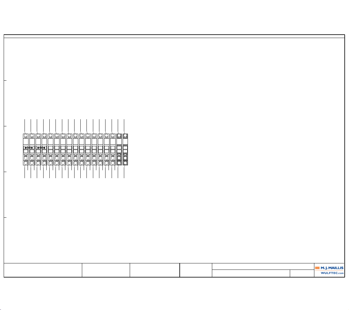
Revision
1 AS BUILT
Date
10/27/2006
Name
A.B.
Verified By: GUY LOPES
6ESLR00107
WULFTEC MJ MAILLIS
WULFTEC MJ MAILLIS
209 WULFTEC
QUEBEC, CANADA
Page Title:
Dwg. No.:
TERMINAL DIAGRAM: TB-101
403
Drawn By: ANDRÉ BUREAU
Page: 403MODULAR WRAPPER
External targets Wiring Internal Target
TERMINAL STRIP:
Wiring
FUNCTION:
Terminal
Location
External Target
Location
Internal Target
Location
(400A3)SLR-01B:REDCBL-401:BRNCON-01:6 BRN(400A4)
1
SLR-01:2(400A3)
CBL-402:BRNPE-02:BRN(400C6)
2
(400C3)
(400A3)SLR-01B:BLKCBL-401:BLUCON-01:2 BLU(400A4)
3
SLR-01:3(400A3)
CBL-402:BLUPE-02:BLU(400C6)
4
(400C3)
(400B8)SLR-01B:WHTCBL-401:PNKCON-01:5 PNK(400B7)
5
SLR-01:4(400B8)
(400B8)SLR-01B:GRNCBL-401:BLKCON-01:3 BLK(400B7)
6
SLR-01:5(400B8)
(400B8)SLR-01B:ORGCBL-401:WHTCON-01:1 WHT(400B7)
7
SLR-01:6(400B8)
(400C8)SLR-01B:BLUCBL-401:GRYCON-01:4 GRY(400C7)
8
SLR-01:7(400C8)
(400C8)SLR-01B:RED/BLKCBL-402:BLKPE-02:BLK(400C6)
9
SLR-01:9(400C8)
(401C2)SLR-02B:BLKCBL-405:BLKPRESTRETCH U:_0(401D2)
10
SLR-01:12(401D2)
(401C2)SLR-02B:WHTCBL-405:WHTPRESTRETCH V:_0(401D2)
11
SLR-01:13(401D2)
(401C2)SLR-02B:REDCBL-405:REDPRESTRETCH W:_0(401D2)
12
SLR-01:14(401D2)
(401C4)SLR-03B:BLKCBL-407:BLKMTR-02:T1(401E5)
13
SLR-01:15(401D4)
(401C4)SLR-03B:WHTCBL-407:WHTMTR-02:T2(401E5)
14
SLR-01:16(401D4)
(401C5)SLR-03B:REDCBL-407:REDMTR-02:T3(401E5)
15
SLR-01:17(401D5)
(401C2)SLR-02B:GRNCBL-405:GRNPRESTRETCH GND:_0(401D2)
16
SLR-01:20(401D2)
CBL-407:GRNMTR-02:G(401E5)
17
(401D4)
TB-101 ROTARY ARM JB
E
D
C
B
A
1 2 3 4 5 6 7 8 9 10
Page 100
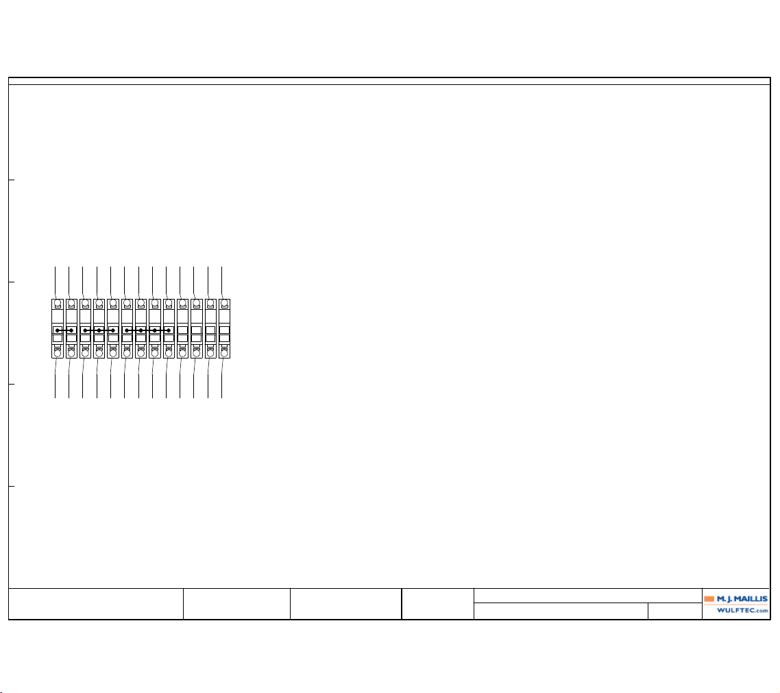
Revision Date Name
Verified By:
6ESLR00107
WULFTEC MJ MAILLIS
WULFTEC MJ MAILLIS
209 WULFTEC
QUEBEC, CANADA
Page Title:
Dwg. No.:
TERMINAL DIAGRAM: TB-102
404
Drawn By: ANDRÉ BUREAU
Page: 404MODULAR WRAPPER
External targets Wiring Internal Target
TERMINAL STRIP:
Wiring
FUNCTION:
Terminal
Location
External Target
Location
Internal Target
Location
(400A4)CON-01:BRNPCBL-04:BRNPS-02:BRN(400A6)
1
CON-01:6 BRN(400A5)
PCBL-03:BRNPE-01:BRN(400C6)
2
(400C5)
(400A4)BLUPCBL-04:WHTPS-02:BLU(400A6)
3
CON-01:2 BLU(400A5)
AS-01:BLUAS-01:BLU(400B6)
4
(400B5)
PCBL-03:BLUPE-01:BLU(400C6)
5
(400C5)
PCBL-04:BLKPS-02:BLK(400A6)
6
(400A7)
PCBL-01:REDLS-01:11(400B6)
7
(400B5)
PCBL-02:REDLS-02:11(400B6)
8
(400B5)
AS-01:BRNAS-01:BRN(400B6)
9
(400B5)
(400B7)CON-01:PNKPCBL-01:BLKLS-01:12(400B6)
10
CON-01:5 PNK(400B7)
(400B7)CON-01:BLKPCBL-02:BLKLS-02:12(400B6)
11
CON-01:3 BLK(400B7)
(400C7)CON-01:GRYPCBL-03:BLKPE-01:BLK(400C6)
12
CON-01:4 GRY(400C7)
(400B7)CON-01:WHTAS-01:BLKAS-01:BLK(400B6)
13
CON-01:1 WHT(400B7)
TB-102 CARRIAGE
E
D
C
B
A
1 2 3 4 5 6 7 8 9 10
 Loading...