

Page 1

Chelton Avionics Inc.
A Chelton Group Company
6400 Wilkinson Drive
Prescott, AZ 86305
U.S.A.
Series III Avionics
Pilot's Guide
Publication No. 150-040564 Rev. A January 2000
Page 2

Series III Avionics
Pilot's Guide
Wulfsberg Electronics Division, located in Prescott, Arizona, designs and manufactures the Chelton
Series III line of products, including the VCS-40A VHF Communications System. For more than 25 years,
Wulfsberg Electronics has distinguished itself by providing top quality avionics products for civil, air
transport, and military applications.
Information in this manual is subject to change without notice. No part of this manual may be reproduced
or transmitted in any form or by any means, electronic or mechanical, without express written permission
of Chelton Avionics, Inc.
Chelton Avionics, Inc. makes no warranty, expressed or implied, with regard to this manual, including but
not limited to any implied warranties of merchantability, fitness for a particular purpose, and noninfringement. In addition, Chelton Avionics, Inc. makes no warranty with regard to the documentation or
data contained herein. Chelton Avionics, Inc. is not liable in the event of incidental, special,
consequential, or any other damages in connection with or arising from furnishing, performance, or use of
this manual.
2000 Chelton Avionics, Inc. All rights reserved
VCS-40A, VC-401B, CD-402B, VNS-41A, VN-411B, CD-412B, CD-413B, TRS-42A, TR-421B, CD-422B,
DFS-43A, DF-431B, CD-432B, DMS-44A, DM-441B, and SD-442B are trademarks of Chelton Avionics, Inc.
Page ii
Page 3

Series III Avionics
VCS-40A VHF Communications System...................................................................................................................1
General Description................................................................................................................................................1
CD-402B Control Display Unit..............................................................................................................................2
CD-402B Controls (Fixed Channel Spacing) .........................................................................................................3
CD-402B Controls (Switchable Channel Spacing).................................................................................................3
CD-402B Controls (All).........................................................................................................................................4
CD-402B Display...................................................................................................................................................5
Operating the VCS-40A .........................................................................................................................................6
VCS-40A Notes......................................................................................................................................................8
VCS-40A System Block Diagram (Typical) ..........................................................................................................9
VNS-41A VHF Navigation System...........................................................................................................................10
General Description..............................................................................................................................................10
CD-412B Control Display Unit............................................................................................................................11
VNS-41A Controls...............................................................................................................................................12
VNS-41A Display.................................................................................................................................................13
Operating the VNS-41A.......................................................................................................................................15
VNS-41A Notes....................................................................................................................................................16
VNS-41A System Block Diagram (Typical)........................................................................................................17
Pilot's Guide
TRS-42A ATC Transponder System........................................................................................................................18
General Description..............................................................................................................................................18
CD-422B Control Display Unit............................................................................................................................19
TRS-42A Controls................................................................................................................................................20
CD-422B Display.................................................................................................................................................23
Operating the TRS-42A........................................................................................................................................25
TRS-42A Notes ....................................................................................................................................................26
TRS-42A System Block Diagram (Typical).........................................................................................................27
DFS-43A Automatic Direction Finder System........................................................................................................28
General Description..............................................................................................................................................28
CD-432B Control Display Unit............................................................................................................................29
DFS-43A Controls................................................................................................................................................30
Operating the DFS-43A........................................................................................................................................34
DFS-43A Notes ....................................................................................................................................................35
DFS-43A System Block Diagram (Typical).........................................................................................................36
DMS-44A Distance Measuring System....................................................................................................................37
General Description..............................................................................................................................................37
SD-442B Selector Display Unit............................................................................................................................38
DMS-44A Controls...............................................................................................................................................39
Operating the DMS-44A.......................................................................................................................................41
DMS-44A Notes...................................................................................................................................................42
DMS-44A System Block Diagram (Typical) .......................................................................................................43
Page iii
Page 4

Series III Avionics
Pilot's Guide
VCS-40A VHF Communication System
General Description
The Chelton VCS-40A VHF Communications System is a fully synthesized ATC VHF transceiver. The
VCS-40A system consists of a lightweight, remote-mounted VC-401B transceiver and a panel-mounted
CD-402B Control Display Unit.
The VC-401B transceiver is available with fixed 25 kHz channel spacing, fixed 8.33 kHz channel spacing
for European airspace, and switchable 25 kHz - 8.33 kHz channel spacing. Operation over the frequency
range of 118.00 – 136.975 MHz is standard. Extended operation over the frequency range of 118.00 –
151.975 MHz is available as an option .
The VC-401B features a coherent squelch system that permits the receiver to respond only to on-channel
signals, rejecting high-level noise. This makes it ideal for CLIMAX operations. The system also features
built-in SELCAL and ACARS capabilities for regional airlines and major fleet operators.
Reliability of the VC-401B is substantially increased by a specially designed thermal protective device that
enables continuous operation at reduced power (instead of the full 20 watts rated output) without
damaging the transceiver. A heavy-duty heat sink accommodates continuous operation, and a unique
cooling fin design dissipates heat, decreases internal unit temperatures and increases service life.
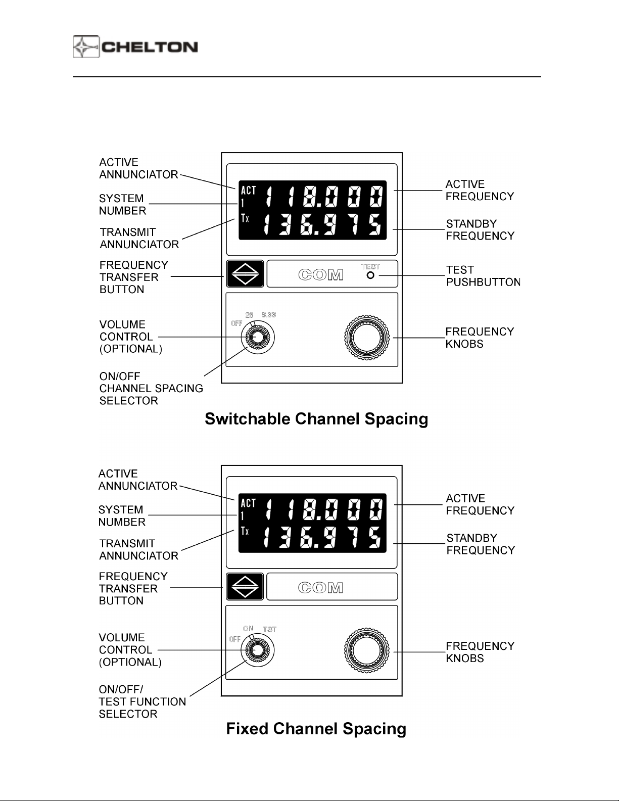
The CD-402B Control Display Unit is available in versions for use with transceivers with fixed channel
spacing (25 kHz or 8.33 kHz), and for units with switchable (25 kHz and 8.33 kHz) channel spacing.
The CD-402B Control Display Unit provides a simultaneous readout of two frequencies: The active
frequency in the upper display and, immediately below it, the standby frequency. Frequency switching is
accomplished by simply pressing a frequency transfer button. The Transmit Annunciator (Tx) appears in
the display when RF is present at the output of the transceiver, providing positive proof-of-operation.
When the VC-401B System is turned on, a diagnosis of all critical circuits begins, and continues until the
System is turned off. If a fault is detected at any time, a FAIL annunciation appears in the display.
The VCS-40A System has a nonvolatile memory which allows it to remember the last frequencies
displayed, indefinitely, even when power is removed. This feature prevents momentary power interrupts
from affecting the system, and allows the last frequencies used to appear immediately when the System
is turned on.
The VCS-40A System provides ARINC format 429 output for external use, and can also be tuned by
ARINC format 429 commands from external equipment such as an RMS-555 Radio Management
System.
Page 1
Page 5
Series III Avionics
CD-402B Control Display Unit
Pilot's Guide
Page 2
Page 6
Series III Avionics
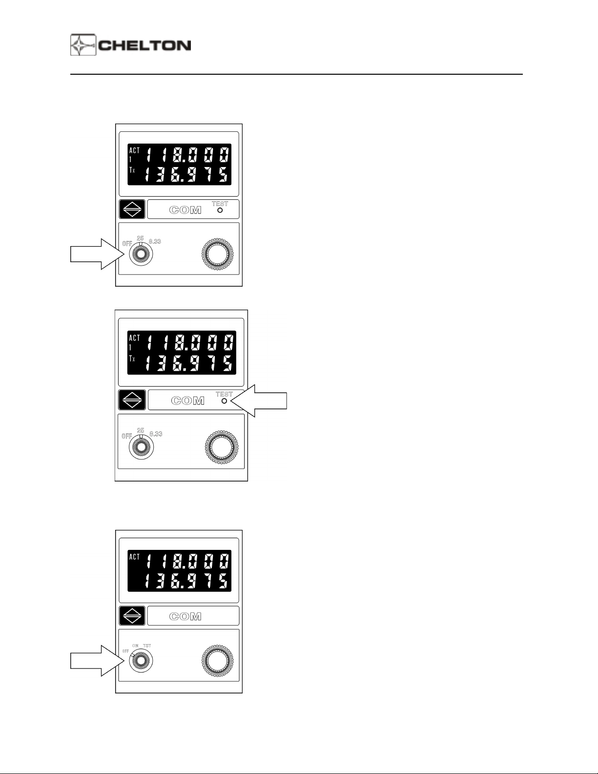
CD-402B Controls (Switchable Channel Spacing)
Pilot's Guide
Off/On Channel Spacing Selector and TEST
Pushbutton
OFF
the last frequencies displayed in the system's
non-volatile memory.
25
- Activates the VCS-40A System. Selects 25 kHz
channel spacing. The last frequencies displayed
reappear on the display.
8.33
frequencies displayed reappear on the display.
TEST Pushbutton
- Deactivates the VCS-40A System. Records
- Selects 8.33 kHz channel spacing. The last
Disables the squelch circuits to allow audible
verification of receiver operation.
CD-402B Controls (Fixed Channel Spacing)
Off/On/Test Function Selector
OFF
the last frequencies displayed in the system's
non-volatile memory.
ON
frequencies displayed reappear on the display.
- Deactivates the VCS-40A System. Records
- Activates the VCS-40A System. The last
TST
- Disables the squelch circuits to allow audible
verification of receiver operation.
Page 3
Page 7
Series III Avionics
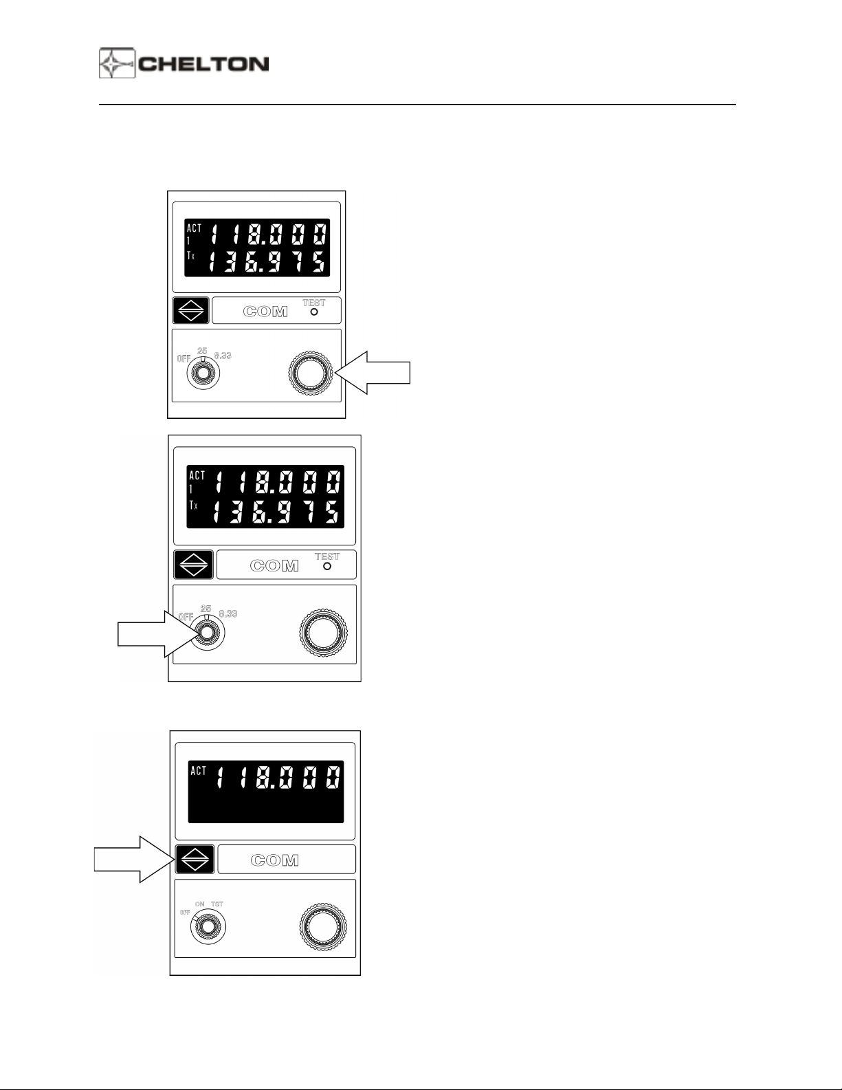
CD-402B Controls (All)
Pilot's Guide
Frequency Knobs
The outer knob tunes the transmit/receive frequency
in whole MHz steps (118, 119, 120, etc.). The inner
knob tunes in 25 or 8.33 kHz steps (refer to the table
on page 6).
Volume Control (Optional)
the receiver audio volume.
Frequency Transfer Button
Press and release to exchange active and standby
frequencies. Press and hold 2 seconds to remove
the standby frequency so that the active frequency
can be changed. Press and hold 2 seconds again to
restore the standby frequency.
- Inner knob controls
Press and hold for 7 seconds or longer to set the
active frequency to 121.50 MHz.
Page 4
Page 8
Series III Avionics
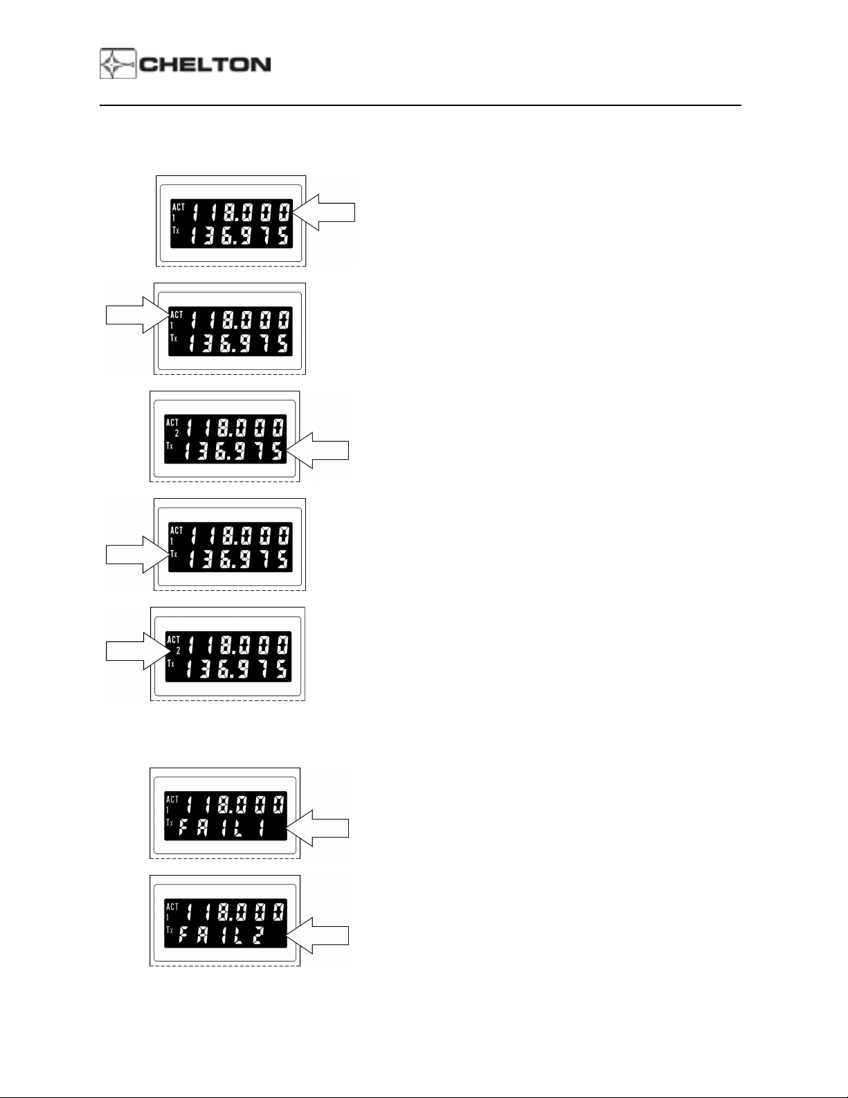
CD-402B Display
Pilot's Guide
Active Frequency
The upper line of the display always shows the active
frequency
Active Annunciator
…which is indicated by the Active Annunciator (the letters
ACT).
Standby Frequency
The lower line of the display shows the standby frequency.
When both frequencies are shown, rotating the
FREQUENCY KNOBS changes the standby frequency.
…
Transmit Annunciator
The Transmit Annunciator (the letters Tx) indicates an RF
output of the transmitter. It appears when the microphone
is keyed.
System Number
The System Number indicates that this display is for COM
System 2 (when more than one system is installed). The
number 1 indicates that this display is for COM System 1
(when more than one system is installed).
If only one COM System is installed or if this Control
Display Unit controls COM 3 in a three-radio system, the
display shows a blank instead of 1 or 2.
FAIL 1
failure. Neither transmitter nor receiver is operative.
FAIL 2
Transmitter only failure. This is displayed only when the
microphone is keyed. The receiver is still operative unless
FAIL 1
in the lower line of the display indicates a System
in the lower line of the display indicates a
is displayed with the mic rophone not k e yed.
Page 5
Page 9

Series III Avionics
Operating the VCS-40A
1. Turn the SELECTOR to ON (fixed channel spacing) or to 25 or 8.33 (switchable channel spacing).
The last frequencies selected prior to System turnoff reappear in the display.
2. If these are not the desired frequencies, rotate the appropriate FREQUENCY KNOB until the desired
frequency is displayed as the standby frequency in the lower line of the display.
The large frequency knob increments (clockwise rotation) or decrements (counter-clockwise rotation)
the frequency being tuned by one megahertz for each detent.
The small frequency knob increments (clockwise rotation) or decrements (counter-clockwise rotation)
the frequency being tuned by 25 kHz or 8.33 kHz for each detent.
For 8.33 kHz channel spacing, the small frequency knob sequences through a list of both 25 kHz and
8.33 kHz channels (see table below).
Frequency (MHz) Channel Spacing (kHz) Channel Name
Pilot's Guide
118.0000 25 118.000
118.0000 8.33 118.005
118.0083 8.33 118.010
118.0167 8.33 118.015
118.0250 25 118.025
118.0250 8.33 118.030
118.0333 8.33 118.035
118.0417 8.33 118.040
118.0500 25 118.050
118.0500 8.33 118.055
118.0583 8.33 118.060
118.0667 8.33 118.065
118.0750 25 118.075
118.0750 8.33 118.080
118.0833 8.33 118.085
118.0917 8.33 118.090
118.1000 25 118.100
.
.
.
136.9750 25 136.975
136.9750 8.33 136.980
136.9833 8.33 136.985
136.9917 8.33 136.990
.
.
Page 6
Page 10

Series III Avionics
3. Press and release the FREQUENCY TRANSFER button. This exchanges the two displayed
frequencies. The desired frequency is now active and may be used immediately.
4. Use the VOLUME CONTROL to adjust volume if a station is broadcasting.
5. To set a new standby frequency, rotate the appropriate FREQUENCY KNOB until the desired
frequency is displayed in the lower line of the display.
Pilot's Guide
NOTE:
To tune the active frequency only (without first tuning the standby and then "flipping" the
frequencies), press and hold the FREQUENCY TRANSFER button for two seconds, then
release it. This removes the standby frequency from the display.
The FREQUENCY KNOBS may now be used to change the active frequency.
Press and hold the FREQUENCY TRANSFER button for two seconds again to restore the
standby frequency to the display, if desired.
Page 7
Page 11

Series III Avionics
VCS-40A Notes
1. The FREQUENCY SELECTOR knobs tune the VC-401B transceiver directly. The display shows the
frequencies to which the VC-401B transceiver is actually tuned. The transceiver may also be tuned
by an ARINC 429 digital bus.
2. Display intensity and panel lighting are controlled by external dimmer controls.
3. Pressing and holding the FREQUENCY TRANSFER button for at least 7 seconds before releasing it
sets the COM frequency to 121.50 MHz. This is true even if segments of the display are faulty or a
lighting failure occurs. From this known reference point, any other frequency may be set by counting
detents of the FREQUENCY SELECTOR knobs as they are rotated. Each clockwise detent of the
outer knob is one Megahertz difference. Each clockwise detent of the inner knob is 25 or 8.33 kHz
difference.
4. The FREQUENCY SELECTOR knobs rotate continuously through all detents without end stops.
After rotating the outer knob clockwise to the highest number, the next detent will be the lowest
number (118 MHz).
Pilot's Guide
Page 8
Page 12
Series III Avionics
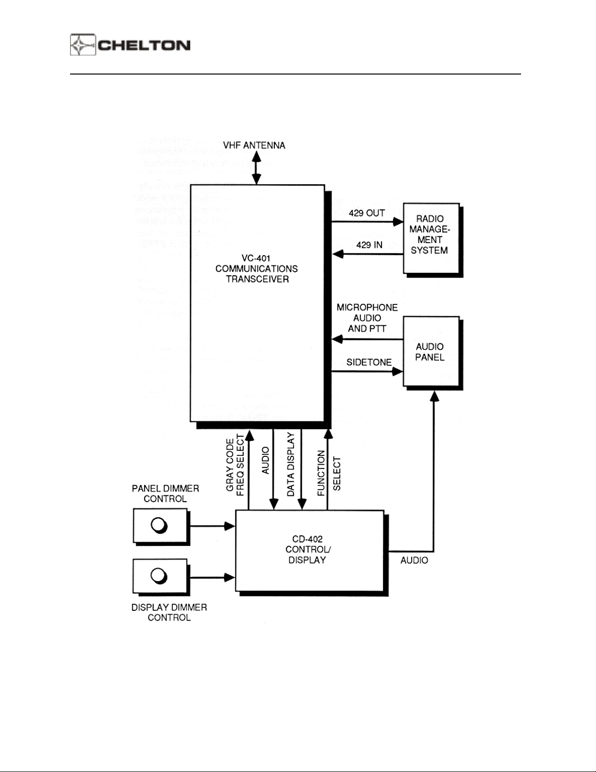
VCS-40A System Block Diagram (Typical)
Pilot's Guide
Page 9
Page 13

Series III Avionics
Pilot's Guide
VNS-41A VHF Navigation System
General Description
The Chelton VNS-41A VHF Navigation System is a lightweight 200-channel microprocessor-based VHF
navigation receiving system that combines VOR/LOC, glideslope, and marker beacon reception in the
same unit. The VNS-41A is compatible with most HSIs, CDIs, and conventional marker beacon displays.
The ARINC 429 serial data bus interface is compatible with EFIS displays, radio management systems
(RMU), and flight management systems (FMS).
The VNS-41A system consists of a remote mounted VN-411B VHF Navigation Receiver and a panel
mounted CD-412B or CD-413B Control Display Unit.
In addition to processing signals for external use (Marker Beacon Lamps and audio, AFCS, CDI, HSI,
EFIS, etc.), the VNS-41A can digitally display BEARING TO or RADIAL FROM any selected VOR station
on the CD-412B/CD-413B with the function selector panel control.
When an ILS frequency is selected by the VNS-41A, the letters LOC appear below the frequency on the
display when RAD or BRG are selected.
Digital circuit design of the VNS-41A incorporates microprocessor technology to achieve performance,
reliability, accuracy, and features not possible in previous systems. These include advanced filtering
techniques, full-time self-diagnostics, non-volatile frequency memory and continuous calibration.
Special filtering circuits virtually eliminate noise, including rotor modulation noise in helicopter
installations. Self-testing begins when the system is turned on, and continues until turnoff. Faults
detected result in a FAIL annunciation.
Non-volatile memory means that the last frequency selected is in system memory if the system is turned
off, if power is interrupted, or even if the system is removed from the aircraft!
The VNS-41A is TSO'd. It is fully compatible with other equipment using ARINC Characteristic 429
Digital Information Transfer. Frequencies may be controlled remotely by a Navigation Management
System (NMS) and interfaced with an Area Navigation (RNAV) System.
Page 10
Page 14
Series III Avionics
CD-412B Control-Display
Pilot's Guide
Page 11
Page 15

Series III Avionics
VNS-41A Controls
Pilot's Guide
Function Selector and Volume Control
OFF - Deactivates the VNS-41A System.
Records the last frequencies displayed
into the system's non-volatile memory.
ON - Activates the VNS-41A System. The last
frequencies displayed reappear on the
display.
RAD - Displays the radial the aircraft is on from
the selected VOR. It is displayed digitally
below the selected VOR frequency.
BRG - Displays the bearing to the selected
VOR. It is displayed digitally below
selected VOR frequency.
Volume Control - (Inner Knob) adjusts the audio
volume of selected the station.
Frequency Selector
The outer knob tunes the receiver in whole MHz
steps (108, 109, 110, etc., up to 117 MHz).
The inner knob tunes fractional MHz
frequencies in 50 kHz steps (.00, .05, .10, .15,
etc., up to .95).
Frequency Transfer Button
Press and release to exchange the active and
standby frequencies when both are displayed.
Press and hold 2 seconds to remove the
standby frequency so the active frequency may
be tuned (press again and hold 2 seconds to
restore the standby frequency).
Page 12
Press and hold 7 seconds to tune the receiver to
108.00 MHz.
Page 16

Series III Avionics
VNS-41A Display
Pilot's Guide
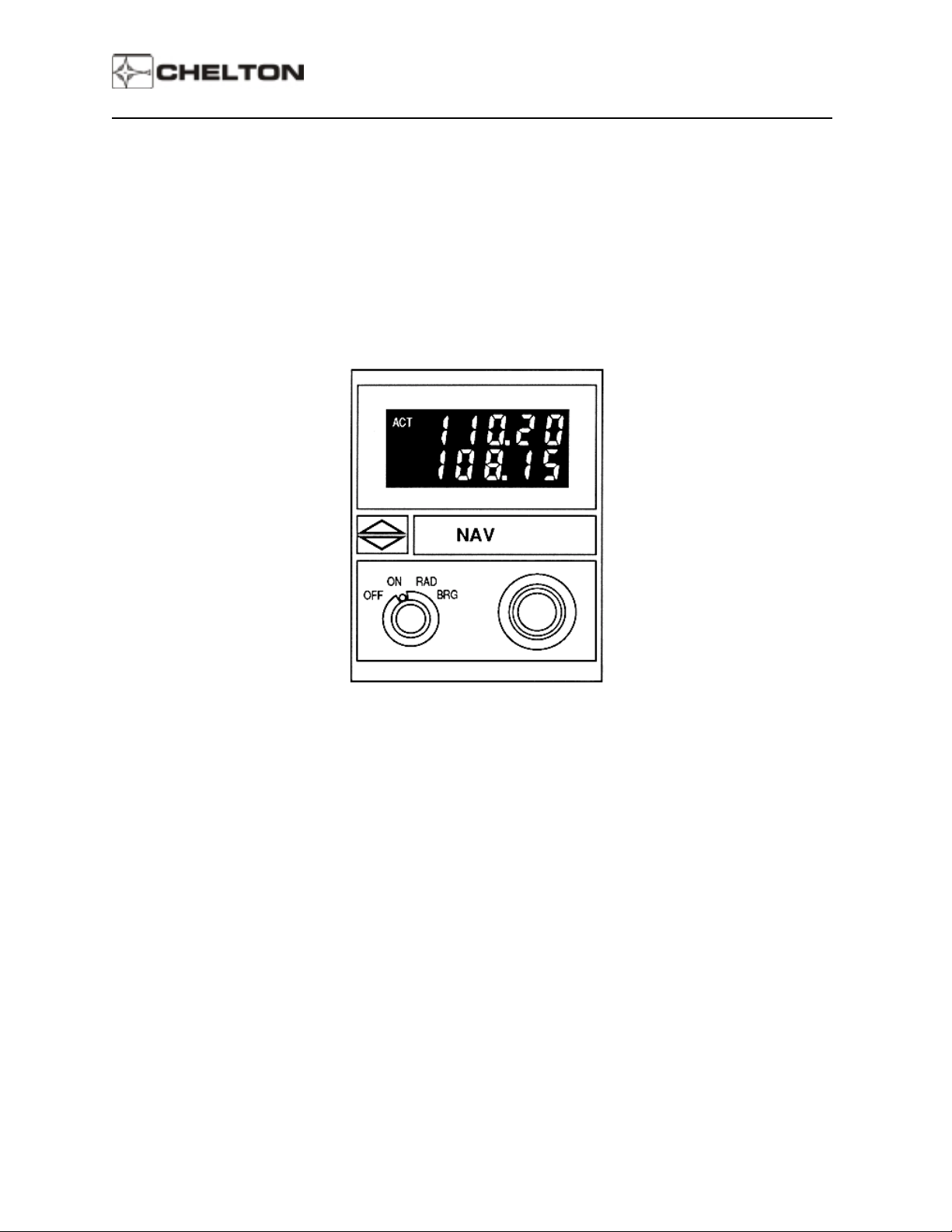
When the VNS-41A is turned on, the last display
before turnoff is displayed again.
The upper line of the display always shows the
active frequency (indicated by the letters ACT. The
lower display may show the standby frequency,
digital radial or bearing, or LOC annunciation,
depending on the FUNCTION SELECTOR setting.
When two frequencies are displayed, rotating the
FREQUENCY knobs changes the bottom (standby)
frequency.
If the FUNCTION SELECTOR switch is set to RAD
when a VOR frequency is active (shown on the top
line), the bottom line displays the radial the aircraft
is on FROM the VOR station.
In this mode, the FREQUENCY TRANSFER button
is disabled.
If the FUNCTION SELECTOR switch is set to BRG
when a VOR frequency is active (shown on the top
line) the bottom line displays the bearing TO the
VOR station.
Three dashes on the bottom line indicates a flag
condition. This flag means that RAD or BRG has
been selected on the FUNCTION SELECTOR
switch but cannot be displayed because of
insufficient signal or during VOR station passage.
Page 13
Page 17

Series III Avionics
Pilot's Guide
When the top (active) frequency is a localizer
station, bearing or radial cannot be displayed.
Setting the FUNCTION SELECTOR switch to BRG
or RAD will cause the letters LOC to appear on the
bottom line instead of the standby frequency. This
is a reminder that this display cannot be used for
bearing or radial data while on an ILS approach.
NOTE:
The number 1 below the letters ACT represent Nav
System 1 when more than one NAV System is
installed. This number is fixed at the time of
installation.
The number 2 below the letters ACT represent Nav
System 2 when more than one Nav System is
installed. This number is fixed at the time of
installation. A blank below the letters ACT
represent either Nav System 3 (when more than 2
Nav Systems are installed) or that only one Nav
System is installed.
When LOC is displayed, return the
FUNCTION SELECTOR to the ON
position so that the standby frequency is
displayed instead.
A FAIL annunciation appears in the lower display to
indicate failure of the VNS-41A System. Fail
messages and their meanings are:
• FAIL 1: NAV synthesizer out of lock.
• FAIL 2: G/S synthesizer out of lock.
• FAIL 3: NAV converter A/D check fail.
• FAIL 4: Non-volatile memory fail.
These annunciations are the result of a continual
system self-test, and indicate that maintenance is
required before the system may be used.
Page 14
Page 18

Series III Avionics
Operating the VNS-41A
1. Set the FUNCTION SELECTOR to ON.
2. If these are not the desired frequencies, rotate the FREQUENCY KNOBS until the desired frequency
is displayed on the bottom portion of the display
3. Press and release the FREQUENCY TRANSFER button. This exchanges the two displayed
frequencies. The desired frequency is now active and may be used immediately.
4. Adjust the VOLUME CONTROL for the desired audio level.
5. Rotate the FREQUENCY KNOBS until the desired standby frequency appears on the bottom portion
of the display.
Pilot's Guide
NOTE:
To tune the active frequency only (without first tuning the standby and then "flipping" the
frequencies), press and hold the FREQUENCY TRANSFER button for two seconds, then
release it. This temporarily removes the standby frequency from the display.
Now the FREQUENCY KNOBS may be used to change the active frequency. The active
frequency may be used immediately.
To restore the standby frequency to the display, press and hold the FREQUENCY
TRANSFER button two seconds.
Page 15
Page 19

Series III Avionics
VNS-41A Notes
1. The FREQUENCY SELECTOR KNOBS tune the VNS-41A receiver directly. The display is directly
controlled by the receiver, so the frequency display shows the actual frequency to which the receiver
is tuned. The transceiver may also be tuned by an external ARINC 429 digital data bus.
2. The VOLUME control on the CD-412B control/display does not adjust the volume of the Marker
Beacon receiver in the VNS-41A receiver. This volume is preset. Typically, Marker Beacon volume
is adjusted by a control on an audio control panel.
3. Display intensity and panel lighting are controlled by external dimmer controls.
4. Pressing and holding the FREQUENCY TRANSFER button for at least 7 seconds before releasing it
sets the active frequency to 108.00 MHZ. Because the display is controlled by the receiver (see Note
1 above), the receiver will tune to this frequency even if the display is defective. From the known
reference of 108.00 MHz as a starting point, any other frequency may be selected by counting
detents. Each clockwise detent of the outer knob is one MHz difference (108, 109, 110, etc.). Each
clockwise detent of the inner knob is .05 MHz difference (.00, .05, .10, .15, etc.). For example,
rotating the outer knob clockwise three detents would put the frequency at 111.00 MHz. Then
rotating the inner knob clockwise three detents would then put the frequency at 111.15 MHz.
Pilot's Guide
5. The FREQUENCY SELECTOR knobs rotate continuously through all detents without end stops. For
example, the next clockwise detent of the outer knob after 117 is 108; the next clockwise detent of the
inner knob after .95 is 00.
Page 16
Page 20

Series III Avionics
VNS-41A System Block Diagram (Typical)
Pilot's Guide
Page 17
Page 21

Series III Avionics
Pilot's Guide
TRS-42A ATC Transponder System
General Description
The Chelton TRS-42A ATC Transponder System is a digital, microprocessor-controlled 325 Watt
transponder that allows positive identification in the Air Traffic Control environment. Features include:
Dual transmitter output devices
Encoding altimeter readout
Dual transponder control from a single Control Display Unit.
Full-time automatic and pilot-selected self-test
"Quick-select" VF R m ode
The TRS-42A system consists of a TR-421B Transmitter/Receiver and a CD-422B Control Display Unit.
The TR-421B Transmitter-Receiver unit assures accurate and dependable service. The unit provides
4,096 discrete response codes plus modes A and B, as well as mode C - altitude reporting (when
connected to an encoding altimeter). The unit uses a single-chip microprocessor to assure code data
validity and condition of all critical circuits.
The CD-422B Control-Display Unit has the unique capability to control a dual transponder installation with
a single control head. Selection is made by simply pressing a selector button on the front panel.
The CD-422B also provides an annunciation of the letters "ID" whenever the transponder replies to an
interrogation. When the mode selector is in the VFR position, the active transponder is channeled to the
1200 code (VFR). This code may be programmed to other international VFR codes.
To aid in channel selection, the code selection knobs of the CD-422B provide variable-rate tuning for
greater speed and accuracy. Rapid rotation of a knob causes large changes in the code, while slow
rotation changes code digits slowly, one digit at a time. Also, there is no need to change to standby mode
before changing channels, because the new code will not be transmitted until the selector knobs have
remained stationary for 3 seconds. Whenever an emergency code from 7500 to 7700 is selected, the
display will blink on and off for 3 seconds before transmission.
Page 18
Page 22

Series III Avionics
CD-422B Control Display Unit
Pilot's Guide
Page 19
Page 23

Series III Avionics
TRS-42A Controls
Pilot's Guide
Function Selector
OFF - Deactivates the TRS-42A System.
Records the last data displayed into the
system's non-volatile memory.
TST - Displays barometric altitude from an
encoding altimeter in the lower line of the
display. An un successful test displays
FAIL in upper line of the display.
Pressing the IDENT button in the TST
mode causes upper line of the display to
read 8888 and lower line to read 88888.
Page 20
Page 24

Series III Avionics
Pilot's Guide
SBY - Applies power to the TRS-42A system
circuits without activating the transmitter.
The last displayed code appears in the
upper line of the display and may be
changed with CODE SELECT knobs.
Lower line of the display is blank.
ON - Enables the TRS-42A to respond to ATC
radar interrogations. Altitude is not
encoded into the TRS-42A response.
ALT - Same as ON except altitude is encoded
into the response when the TRS-42A is
interrogated by ATC radar. Altitude is not
displayed.
Page 21
VFR - Automatically selects and displays 1200
as the transponder code (other codes
may be programmed for non-U.S.A.
operation). Altitude is still encoded into
responses in this mode, but is not
displayed.
Page 25

Series III Avionics
Pilot's Guide
CODE SELECT Knobs - The outer knob selects the
left two digits of the transponder code. the inner
knob selects the right two digits.
The range for each knob is 00 through 77.
When the FUNCTION SELECTOR is in VFR
position, the CODE SELECT knobs are disabled
because the VFR code (1200 in the U.S.A.) is
automatically selected.
IDENT Pushbutton - During normal operation, this
pushbutton is pressed and released only when ATC
requests "squawk ident". The identification mode
will then remain active for 15 to 30 seconds,
causing the transponder to transmit a special
identification code each time it is interrogated by
ATC radar. The ID annunciation will appear on the
display each time an interrogation occurs. After
this, the TRS-42A will revert to its selected mode
(ON, ALT, or VFR).
TRANSPONDER SYST EM 1 or 2 SELECT
Pushbutton - Selects either System 1 or System 2
when more than one transponder system is
installed. The selected system number is displayed
below the letters ACT on the display. If only one
system is installed, the number 1 is always
displayed.
Page 22
Page 26
Series III Avionics
CD-422B Display
Pilot's Guide
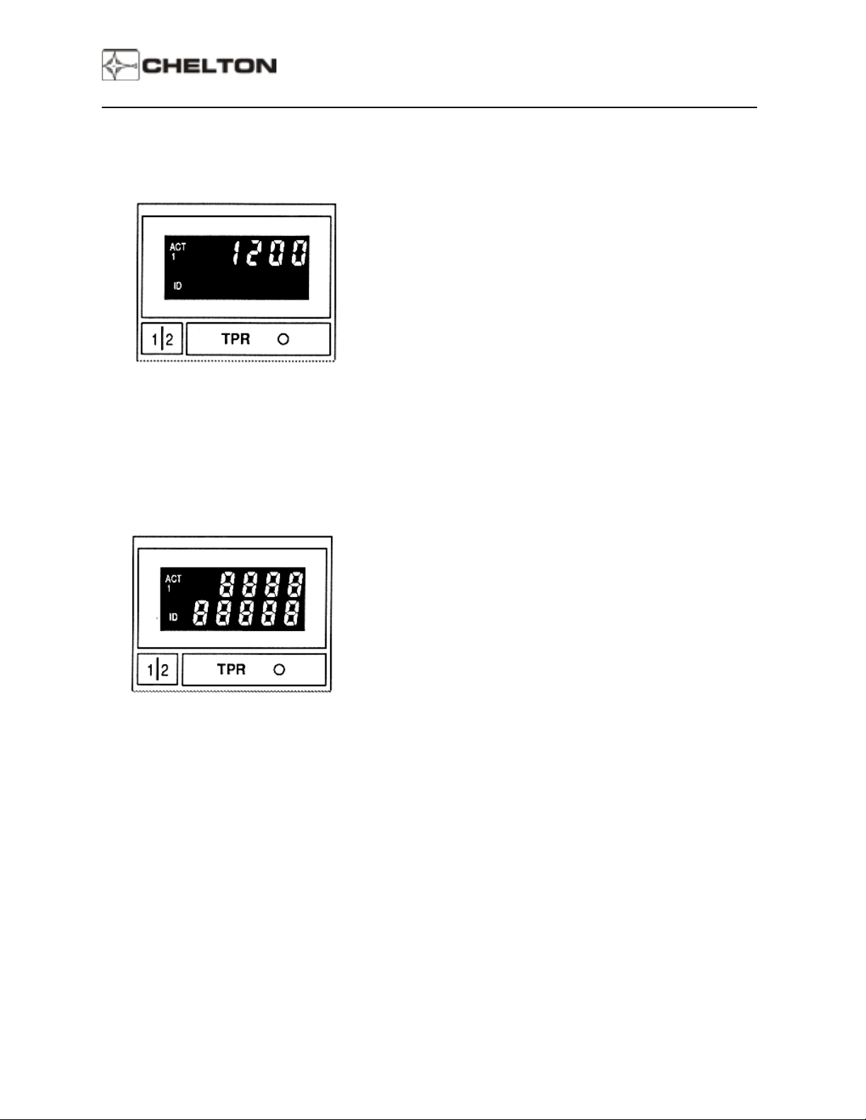
In normal operation, the upper display is the
transponder code. It is selected either by the
CODE SELECT knobs or by setting the FUNCTION
SELECTOR to VFR.
The displayed code is active only when the
annunciation ACT is present in the display.
When a displayed code is changed, the new code
will appear on the display for 3 seconds before the
annunciation ACT appears. This allows the code to
be manually changed before it becomes active if it
is in error, or while "tuning through " one co de on
the way to another one. It is not necessary to go to
SBY to change codes.
In addition to a 3-second delay before becoming
active, emergency codes (7500, 7600, or 7700) will
blink on and off during the 3-second delay, alerting
the pilot that transmission of an emergency
transponder code is imminent.
If the IDENT pushbutton is pressed while the
FUNCTION SELECTOR is in TST mode, the top
line of the display indicates 8888 while the bottom
line indicates 88888.
Page 23
Page 27

Series III Avionics
Pilot's Guide
If a system failure occurs in any mode, the
annunciation FAIL appears in either the upper or
lower line of the display. The system is not usable
in this condition.
Barometric altitude is indic ated in lower line of
display when the MODE SELECTOR is in TST
mode. This is the altitude that will be encoded into
the transponder output when operating in an
altitude-reporting mode (ALT or VFR positions of
FUNCTION SELECTOR).
Page 24
Page 28

Series III Avionics
Operating the TRS-42A
Preflight
1. Set the FUNCTION SELECTOR to TST.
2. Select System 1 or System 2 (if more than one transponder system is installed).
3. Note the encoding barometric altitude in lower display.
4. Press the IDENT pushbutton. Note that the numbers 8888 are present in upper line of the display,
and that 88888 is displayed in lower line.
5. Set the FUNCTION SELECTOR to SBY. The system is now ready for operation.
Flight Operation
1. Use the CODE SELECT knobs to set the requested ATC transponder code into the display.
Pilot's Guide
– OR –
If the flight is VFR and 1200 with altitude reporting is the appropriate code and mode, set the
FUNCTION SELECTOR to VFR.
2. For non-altitude reporting mode, set the FUNCTION SELECTOR to ON.
3. For altitude reporting mode, set the FUNCTION SELECTOR to ALT.
4. If ATC requests "stop altitude squawk", set the FUNCTION SELECTOR to ON.
5. If ATC requests "squawk standby," set the FUNCTION SELECTOR to SBY.
The TRS-42A is programmed to automatically select code 1200 when the FUNCTION SELECTOR is set
to VFR. To program another code for the VFR position, perform the following steps:
1. Set the FUNCTION SELECTOR to SBY position.
2. Press and release the IDENT pushbutton.
3. Select the new code with the CODE SELECT knobs.
4. Press and release the IDENT pushbutton again.
These steps enter the newly selected VFR code into TRS-42A system memory. The new code is in
effect any time the FUNCTION SELECTOR is in the VFR position.
Page 25
Page 29

Series III Avionics
TRS-42A Notes
1. Airborne ATC transponders are designed to operate in the Air Traffic Control Radar Beacon System
(ATCRBS) environment to support inflight aircraft identification and traffic control.
2. Airborne ATC transponders respond to signals from ATC secondary radar that scans the same
volume of airspace as, and in synchronization with, ATC primary radar. The ATC secondary radar
operates on 1030 MHz. On detecting a signal at this frequency, the airborne transponder responds
on a frequency of 1090 MHz.
3. Airborne ATC transponder responses consist of a combination of pulses determined by the position of
the CODE SELECT switches to the CD-422B Control Display Unit. Eight possible digits (0 through 7)
for each digit of the code allow a total of 4096 (8 x 8 x 8 x 8) code combinations.
4. An airborne ATC transponder transmits only when "swept" by the special ATC secondary radar. A
transmission lasts for a few millionths of a second. During this transmission, and for about a half
second afterwards, the letters ID are annunciated on the CD-422B. This informs the pilot that he is in
the ATCRBS environment and that his transponder is functioning normally.
Pilot's Guide
5. Distance Measuring Equipment (DME) and airborne ATC transponders operate in the same
frequency band. To prevent interference, each system generates a special pulse during the time it is
transmitting. This pulse is called a suppression pulse and is wired between units to automatically
prevent simultaneous transmissions that might damage circuits of the receiving system that is
"listening" for very weak signals. This has no effect on DME or ATC Transponder instrumentation in
the cockpit.
Page 26
Page 30
Series III Avionics
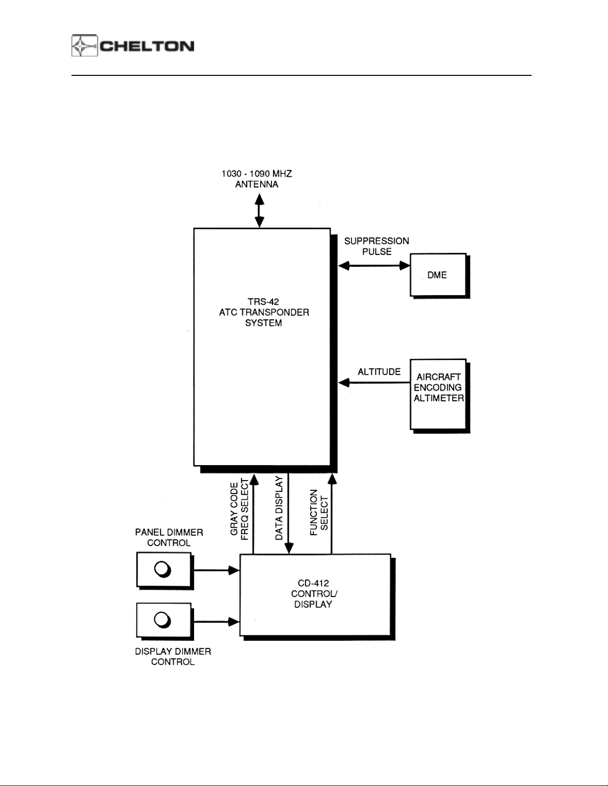
TRS-42A System Block Diagram (Typical)
Pilot's Guide
Page 27
Page 31

Series III Avionics
Pilot's Guide
DFS-43A Automatic Direction Finder System
General Description
The DFS-43A Direction Finder System provides reception of low-frequency navigational aids and AM
broadcast stations in the 190.0 – 1860 kHz frequency range.
The DFS-43A System consists of the DF-431B Receiver, the CD-432B Control Display Unit, and the AT434 Loop/Sense Antenna. This system provides accurate, dependable reception of enroute
nondirectional beacons (NDB), Locator Outer Markers (LOM), and commercial AM broadcast stations.
Microprocessor circuitry controls operation, processes signals, performs self -calibration, and provides
full-time self -diagnostics. This all digital, solid-state design includes a unique signal filter that provides an
extremely stable needle position even in areas of high RF noise.
Special digital circuitry provides a unique steering command that may be used directly by Electronic Flight
Instrument Systems (EFIS) or in conjunction with the Chelton Avionics VNS-41A VHF Navigation System
for electromechanical HSI course deviation display. Analog outputs for standard ADF indicators and RMI
pointers are included.
The DFS-43A certified frequency range is 190 to 1860 kHz, and the international marine HF distress
frequency of 2182 kHz. Frequency tuning may be done by the CD-432B Control Display Unitor by
external equipment such as an RMS-555 Radio Management System.
The active and standby frequency are displayed on the CD-432B simultaneously and stored in nonvolatile
memory. Switching between the two is done by simply pressing a frequency transfer button below the
displayed frequencies.
Advanced heat sink and cooling fin design efficiently collect and dissipate internal heat of the receiver,
providing cooler operating temperatures and longer unit life.
The AT-434 Antenna unit contains a loop antenna, sense antenna, and a solid-state amplifier. The "front
end" of the receiver is actually in the antenna unit, where received signals are processed, converted to an
intermediate frequency and cabled to the receiver. This minimizes effects of electrical noise, and
eliminates the requirement for critical cable lengths between antenna and receiver.
Page 28
Page 32

Series III Avionics
CD-432B Control Display Unit
Pilot's Guide
Page 29
Page 33

Series III Avionics
DFS-43A Controls
Pilot's Guide
Function Selector and Volume Control
OFF - Deactivates the DFS-43A System.
Records the last frequencies displayed in
the system's non-volatile memory.
ANT - Enables the DFS-43A System and the
non-directional sense antenna. The last
frequencies displayed reappear on the
display. Frequency tuning is enabled,
but no direction-finding capability exists
in this mode. External pointers park at
90°.
ADF - Standard direction finding mode. External
indicators point to station.
BRG - Digitally displays the magnetic bearing to
selected station. The FREQUENCY
TRANSFER pushbutton is disabled.
External equipment continues to function
in standard ADF mode.
NOTE:
BFO - (Beat Frequency Oscillator) Identical to
ADF mode, but adds a 1,000-Hz tone to
audio.
Used only to identify interrupted-carrier
signals (also known as cw).
BRG mode is not used for
navigation.
Page 30
Page 34

Series III Avionics
Pilot's Guide
TST - Test Mode
1. Sends a park-at-90° command to external
indicators.
2. Displays the letter L along with a number in
Standby Frequency window, used for
maintenance purposes .
3. Pressing the WH OLE/HALF KHZ button in t his
mode interrupts the park-at-90° command and
provides station relative bearing to external
indicators. Simultaneously, the lower line of the
display will indicate the same relative bearing
digitally to the nearest tenth of a degree.
VOLUME - (inner knob of FUNCTION
SELECTOR). Controls audio level of receiver.
Frequency Knobs
Large (outer) knob tunes the receive frequency
in hundreds of kHz from 1 through 21, skipping
19 and 20.
Small (inner) knob tunes tens and half kHz (see
the WHOLE/HALF KHZ pushbutton switch
description).
Page 31
Page 35

Series III Avionics
Pilot's Guide
When the large knob is rotated clockwise from 18
to the next detent, 2100 will appear in the displa y.
Next, rotating the small knob one detent clockwise
will cause 2182 to appear in the display. The small
knob may then be used to tune from 2181 through
2183 about the maritime emergency frequency of
2182 kHz.
WHOLE/HALF KHZ
between one-half kHz tuning and whole (un its)
tuning by the small FREQUENCY KNOB. When in
the one-half kHz tuning mode, a decimal point will
appear in the display.
In the TST position of the FUNCTION SELECTOR,
pressing the WHOLE/HALF KHZ pushbutton
displays relative station bearing in the lower line of
the display to the nearest tenth of a degree.
FREQUENCY TRANSFER
Momentary pushbutton switch. Pressing and
immediately releasing exchanges the active and
standby frequencies when both are displayed.
Pressing and holding for two seconds before
releasing temporarily removes the standby
frequency. This allows the active frequency to be
changed. Pressing again for two seconds restores
the standby frequency.
Pushbutton switch. Alternates
Pressing and holding for seven seconds or longer
before releasing sets the receiver to its lowest
tunable frequency (100 kHz).
Page 32
Page 36

Series III Avionics
Pilot's Guide
The top line of the display is always the active
frequency, indicated by the letters ACT. The
number 1 or 2 below the letters ACT indicate the
ADF System Number when more than one system
is installed.
Data in the lower line of the display depends on
position of FUNCTION SELECTOR.
In ANT, ADF, or BFO mode, the bottom line of the
display indicates the standby frequency.
In BRG mode, the bottom line of the display
indicates the magnetic bearing of active station. In
this mode the active frequency can be tuned
directly.
Dashes indicate a flag condition.
NOTE:
FAIL 1, FAIL 2 or FAIL 3, 4, 5, 6,
Annunciation indicates a System fault; the
system is not usable in these conditions.
Page 33
Page 37

Series III Avionics
Operating the DFS-43A
1. Set the FUNCTION SELECTOR to ANT. Note that the external ADF pointer moves to 90° and stops.
2. If frequencies displayed are not the ones desired, rotate the FREQUENCY KNOBS until the desired
frequency is displayed on the bottom line of the display.
3. Press and release the FREQUENCY TRANSFER button. This exchanges the two displayed
frequencies. The desired frequency is now active.
Pilot's Guide
NOTE:
4. Adjust the VOLUME control to the desired audio level and identify the station represented by the
active frequency displayed.
5. Rotate the FUNCTION SELECTOR to ADF. Note that the external ADF pointers leave the 90°
parked position and move to indicate the direction to the active station.
6. Rotate the FUNCTION SELECTOR to BRG and read the magnetic bearing shown digitally on the
lower line of the display. Compare this reading with the other ADF displays to assure correct system
operation.
7. Return the FUNCTION SELECTOR to ADF for normal ADF operation.
An alternate tuning method is to press and hold the FREQUENCY TRANSFER button for
two seconds before releasing. This removes the standby frequency from the display and the
active frequency may be tuned by rotating FREQUENCY KNOBS. The system is ready for
immediate operation. If desired, press the FREQUENCY TRANSFER button for two
seconds again to restore standby frequency.
Page 34
Page 38

Series III Avionics
DFS-43A Notes
1. The FREQUENCY SELECTOR knobs tune the DF-431B receiver directly. The display actually
shows the frequencies to which the receiver is tuned. In addition to rotation of the FREQUENCY
SELECTOR KNOBS, the receiver may be tuned by an external ARINC 429 digital bus.
2. Display intensity and panel lighting are controlled by external dimmer controls.
3. If the signal to which the receiver is tuned is lost for longer than 5 seconds, the electromechanical
display pointers will park at 90°.
4. The FREQUENCY SELECTOR KNOBS rotate continuously through all detents without end stops.
After the highest number is displayed, the next detent clockwise will cause the lowest number to be
displayed.
5. If the display is not functioning, the system frequency can be established as follows: Press the
transfer button for 7 seconds. The system will then be at 100 kHz. Rotating the large frequency
selector clockwise will increase the frequency in 100 kHz steps. Rotating the small knob clockwise
will increase the frequency in 1 kHz steps.
Pilot's Guide
6. Frequencies selected between 100 kHz to 189 kHz and 1861 kHz to 1899 kHz are invalid and will
cause the display to blink off and on.
Page 35
Page 39

Series III Avionics
DFS-43A System Block Diagram (Typical)
Pilot's Guide
Page 36
Page 40

Series III Avionics
Pilot's Guide
DMS-44A Distance Measuring System
General Description
The DMS-44A is a digital, solid-state distance measuring system that can provide data from three DME
stations simultaneously. A system consists of a DM-441B transceiver and one or two SD-442B
Selector-Displays. The transceiver unit may be front or rear antenna connector mounted. An efficient,
advanced-design heat sink and cooling fin dissipate internal heat and keep the unit cool even at its full
325 Watt output.
Two DME stations are selectable during routine navigation frequency management - when the pilot
selects VOR/DME's, VORTAC's, MLS/DME's, ILS/DME's, or LOC/DME's. The third DME station is
selectable by an RNAV system for calculating distance to a waypoint, time to a waypoint, and
groundspeed. This third DME channel is selected automatically, independent of any pilot action, and so
is said to be "transparent" to the pilot.
Simultaneous three-channel operation is achieved by high-speed scanning of three different DME
stations. Lock-on to valid data takes less than 200 milliseconds with least-significant-bit accuracy of less
than 0.01 nautical mile. Range is up to 300 nautical miles and ground speed capability is from 0 to 999
knots.
The DMS-44A incorporates the latest microprocessor technology to achieve superior accuracy and
reliability. As soon as power is applied, the DMS-44A begins a continuous self-test of its circuitry. When
circuits do not function within specific parameters, no data is presented, and the word FAIL is
annunciated on the display. The DMS-44A also continuously monitors and analyzes the channel
selection commands being supplied by NAV Receivers and the RNAV System. Invalid command
structure or loss of command continuity results in a FAIL annunciation.
If an active DME signal is temporarily lost or becomes unintelligible, the DMS-44A will continue to
compute and display data based on the last valid signal for up to 12 seconds. This feature provides an
uninterrupted display during manual or automatic channel changes and during aircraft maneuvers that
block the aircraft antenna from line-of-sight to the DME station. If power to the DMS-44A is interrupted,
the last channel and mode used are retained in system memory. When power is reapplied, channel and
mode are restored without external adjustment.
Page 37
Page 41

Series III Avionics
SD-442B Selector Display Unit
Pilot's Guide
Page 38
Page 42

Series III Avionics
DMS-44A Controls
Pilot's Guide
The DMS-44A has only three controls, all located on
the SD-442B Selector-Display Unit. Each is a
momentary, spring-loaded type that releases when
finger pressure is removed. On-off power is through
an external switch such as a radio or avionics
master switch, or a dedicated DME switch. Volume
control of DME station identification audio is also
external, typically located on an audio panel.
NAV - Alternately places annunciator 1, 2, or RNV
in display.
1 - Selects NAV System 1 as the controller of
the DME channel.
2 - Selects NAV System 2 as the controller of
the DME channel.
RNV - Allows the SD-442B Selector Display to
be used as a "repeater" display or
RNAV-computed distance to a waypoint
and ground speed. This allows RNAV
data to be available during times it might
not be displayed by the RNAV System (for
example, when other data is selected for
display on some types of RNAV's).
HOLD
following:
- Pressing and releasing this switch does the
A. Locks the appropriate channel of the
DMS-44A to the current DME frequency in
use. Aircraft wiring will effect the way in
which the hold feature works. In some
installat ions, pin 58 ground, the hold switch
will only place the corresponding channel in
hold. In others, pin 58 open, the hold switch
will place the displayed channel into hold.
B. Displays the current NAV frequency that
determines the DME channel.
C. Disconnects control of the DMS-44A from the
NAV Receiver.
D. Displays annunciation HLD.
The purpose of this switch is to allow the
NAV Receiver to be set to other frequencies
without affecting DME operations. The DME
continues to function on its "holding" channel.
Pressing and releasing this switch while in
the HLD mode will return control back to the
indicated NAV System (1 or 2).
Page 39
Page 43

Series III Avionics
Pilot's Guide
TTS - (Time-To-Station) While this switch is held
pressed, time-to-stat ion wi ll be sho wn on the
display above the switch. When the switch is
released, the display returns to its previous readout
of ground speed. If in hold when the TTS switch is
pressed, the HLD FREQ on the display will blink
twice to alert the pilot.
NOTE:
When DME is being tuned by an MLS,
receive DME hold is inhibited.
Page 40
Page 44

Series III Avionics
Operating the DMS-44A
1. Apply power to the DMS-44A (depending on installation, the power-on switch may be an avionics
master switch, radio switch, or a dedicated DME switch). The SD-442B display(s) will come on
immediately, displaying either data, dashes (flag condition) or the word FAIL.
2. Select a NAV Receiver to control the DM-441B by pressing the NAV pushbutton to display a 1, 2, or
RNAV.
3. To operate the DMS-44A, set the NAV Receiver controlling the DMS-44A to any VHF navaid station
within line-of-sight range that has a DME (VOR/ DME, VORTAC, ILS/DME, LOC/DME, MLS/DME).
4. To use the SD-442B Selector Display as a repeater of RNAV-computed ground speed and distance
to the next RNAV-designated waypoint, press the NAV pushbutton to display RNV.
Pilot's Guide
Page 41
Page 45

Series III Avionics
DMS-44A Notes
1. DME operates within a band of 252 internationally assigned frequency channels from 962 Megahertz
to 1213 Megahertz. All channels are not currently in use, but the DMS-44A is tunable to all 252.
2. DME equipment aboard the aircraft measures the delay between interrogation pulses transmitted and
reply responses received. This delay is converted to distance, and, as distance changes with time, to
ground speed. The distance is "slant range," not horizontal, over-the-ground distance.
3. If a single DMS-44A System is installed with two SD-442B Selector Displays, NAV System 1 may be
selected on one display and NAV System 2 on the other. Each NAV System may then select
separate DME stations.
4. When RNV is selected, the displayed distance is horizontal, not slant, range, distance to the
waypoint. Also, no DME station identification will be present.
5. When turned on, the DMS-44A will remember and display the last mode(s) used, and will be tuned to
the last channels selected before power was removed. On the ground, the display will probably be
flagged because of signal distortions.
Pilot's Guide
6. Because of assigned "pairing" of VHF and MLS navigation facility frequencies with DME channels,
airborne DME equipment is designed to be tuned to the correct DME channel/ frequencies
automatically when a VHF navigation frequency or MLS channel is selected by the pilot. It is not
necessary to know actual DME channel and frequency assignments.
7. When the DMS-44A transmits its interrogation pulses and receives invalid responses or none, the
SD-422 Selector Display indicates this condition by flagging the display with dashes. This is a normal
condition when the ground DME station is out of range, the reply pulses are too weak or unreliable to
process, the ground DME station is out of service, or there is no DME station assigned to the VHF
navigation facility to which the NAV Receiver is tuned.
Page 42
Page 46
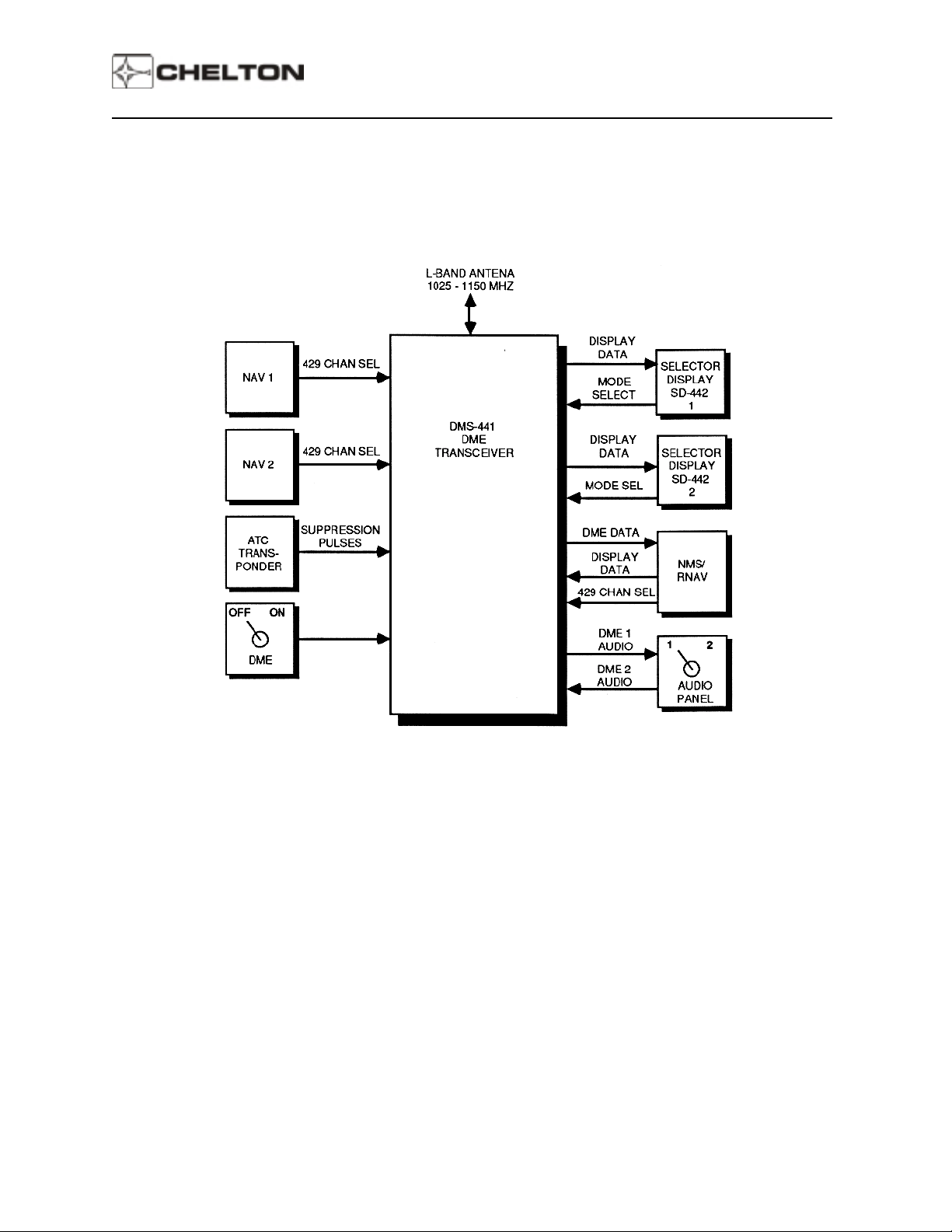
Series III Avionics
DMS-44A System Block Diagram (Typical)
Pilot's Guide
Page 43
 Loading...