


C-5000 COMMUNICATION MANAGEMENT CONTROLLER
INSTALLATION MANUAL
Wulfsberg Electronics Division, located in Prescott, Arizona, designs and manufactures the
C-5000 Communication Management Controller
Wulfsberg Electronics Division makes no warranty, expressed or implied, with regard to this
manual, including but not limited to any implied warranties of merchantability, fitness for a
particular purpose, and non-infringement. In addition, Wulfsberg Electronics Division makes no
warranty with regard to the documentation or data contained herein. Wulfsberg Electronics
Division is not liable in the event of incidental, special, consequential, or any other damages in
connection with or arising from furnishing, performance, or use of this manual.
Reproduction of this publication or any portion thereof by any means is prohibited. For further
information contact Sales, Wulfsberg Electronics Division, 6400 Wilkinson Drive, Prescott,
Arizona, 86301. Telephone: (928) 708-1500.
Information in this manual is subject to change without notice.
2001 Wulfsberg Electronics Division. All rights reserved
C-5000 is a trademark of Wulfsberg Electronics Division.
PROPRIETARY NOTICE
This document contains proprietary information and such information may not be disclosed to
others for any purpose, nor used for manufacturing purposes without written permission from
Wulfsberg Electronics Division.
Page ii Publication No. 150-041118
Table of Contents Rev A
Sep 2001

C-5000 COMMUNICATION MANAGEMENT CONTROLLER
INSTALLATION MANUAL
Record of Revisions
Rev
No.
A9/2001
Rev
Date
Date
Inserted By
Rev
No.
Rev
Date
Date
Inserted By
Publication No. 150-041118 Page iii
Rev A Table of Contents
Sep 2001

C-5000 COMMUNICATION MANAGEMENT CONTROLLER
INSTALLATION MANUAL
Record of Revisions
Rev
No.
Rev
Date
Date
Inserted By
Rev
No.
Rev
Date
Date
Inserted By
Page iv Publication No. 150-041118
Table of Contents Rev A
Sep 2001

C-5000 COMMUNICATION MANAGEMENT CONTROLLER
INSTALLATION MANUAL
TABLE OF CONTENTS
Section 1 - Introduction
1. Using This Manual...................................................................................................... 1-1
2. Components ............................................................................................................... 1-2
A. Communication Managem ent Controller....................................................... 1-2
B. FLEXCOMM II ............................................................................................... 1-2
C. FLEXCOMM I................................................................................................ 1-3
D. Part Numbering.............................................................................................. 1-4
Section 2 - System Installation
1. General.......................................................................................................................2-1
2. System Specifications................................................................................................. 2-1
Page
A. C-5000 Communication Management Controller.......................................... 2-1
B. FLEXCOMM II ............................................................................................... 2-2
C. FLEXCOMM I................................................................................................ 2-8
3. System Interface......................................................................................................... 2-9
A. C-5000 Control Unit/FLEXCOMM II RT System Interface .......................... 2-10
B. C-5000 Control Unit/FLEXCOMM I RT System Interface ........................... 2-11
C. C-5000 Control Unit/Hybrid FLEXCOMM II/FLEXCOMM I Interface.......... 2-12
4. System Operational Modes ...................................................................................... 2-13
A. Single Channel Normal Operation............................................................... 2-13
B. Simulcast Operation .................................................................................... 2-13
C. Relay Operation........................................................................................... 2-13
D. Relay with Simulcast Operation................................................................... 2-13
E. Repeater Operation..................................................................................... 2-13
F. Dual C-5000 Operation................................................................................ 2-13
Publication No. 150-041118 Page v
Rev A Table of Contents
Sep 2001

C-5000 COMMUNICATION MANAGEMENT CONTROLLER
INSTALLATION MANUAL
TABLE OF CONTENTS (cont’d)
SECTION 3 – MECHANICAL INSTALLATION
1. General.......................................................................................................................3-1
2. Unpacking and Inspecting Equipment........................................................................ 3-1
3. General Installation Requirements ............................................................................. 3-2
A. Component Weights...................................................................................... 3-2
4. Installation of Multipin Crimp Connectors................................................................... 3-3
A. Contacts and Crimp Tool Information............................................................ 3-3
B. Contacts and Insertion/Removal Tool Manufacturer Name and Address..... 3-3
5. Installation of C-5000.................................................................................................. 3-3
6. Installation of RT-5000................................................................................................ 3-3
Page
7. Installation of Antennas .............................................................................................. 3-4
A. AT-560 / AT-5000 .......................................................................................... 3-4
B. FC-50............................................................................................................. 3-4
C. AT-550........................................................................................................... 3-4
D. FC-5000......................................................................................................... 3-4
E. AT-50 and AT-51........................................................................................... 3-4
F. FC-50............................................................................................................. 3-5
G. AT-400........................................................................................................... 3-5
H. AT-140........................................................................................................... 3-5
SECTION 4 - ELECTRICAL INSTALLATION
1. General.......................................................................................................................4-1
2. Wiring Considerations................................................................................................. 4-1
A. C-5000 System Interface Connector, P500................................................... 4-2
B. C-5000 Transceiver Interface, RT-5000...................................................... 4-13
C. RT-=5000 Transceiver Installation .............................................................. 4-17
D. C-5000 Communication Management Controller Installation...................... 4-35
E. C-5000 Transceiver Interface FLEXCOMM................................................. 4-37
F. C-5000 Transceiver Interface...................................................................... 4-47
Page vi Publication No. 150-041118
Table of Contents Rev A
Sep 2001

C-5000 COMMUNICATION MANAGEMENT CONTROLLER
INSTALLATION MANUAL
TABLE OF CONTENTS (cont’d)
SECTION 5 – CONFIGURATION AND PROGRAMMING
Introduction.............................................................................................................................. 5-1
Features...................................................................................................................... 5-1
Transceiver Overview................................................................................................. 5-1
Steps to Successful Setup and Operation.................................................................. 5-3
Basic Operation ....................................................................................................................... 5-4
Front Panel & Controls ............................................................................................... 5-4
The Home Page.......................................................................................................... 5-6
Turning the System On and Off.................................................................................. 5-7
Setting the Display Brightness.................................................................................... 5-7
Setting the Volume Level............................................................................................ 5-7
Page
Selecting a Preset Channel Using the Cursor/Value Knob........................................ 5-8
Selecting a Channel Using the Keypad...................................................................... 5-8
Selecting a Channel by Alphanumeric Identifier......................................................... 5-9
Selecting the Manual Channel.................................................................................... 5-8
Using the Direct/Repeat Feature .............................................................................. 5-10
Receiving/Transmitting............................................................................................. 5-10
Enabling/Disabling Transceivers .............................................................................. 5-11
Publication No. 150-041118 Page vii
Rev A Table of Contents
Sep 2001

C-5000 COMMUNICATION MANAGEMENT CONTROLLER
INSTALLATION MANUAL
TABLE OF CONTENTS (cont’d)
SECTION 5 –CONFIGURATION AND PROGRAMMING (cont’d)
Disabling (Turning Off) a Transceiver.......................................................... 5-11
Enabling (Turning On) a Transceiver .......................................................... 5-11
Using the Edit Page............................................................................................................... 5-13
Editing a Preset Channel.......................................................................................... 5-13
Editing a Manual Channel......................................................................................... 5-14
Changing PL and DPL (CTCSS and DCS) Tones ................................................... 5-14
Turning Tones Off........................................................................................ 5-14
Selecting a CTCSS Tone ............................................................................ 5-15
Selecting a DCS Tone ................................................................................. 5-15
Changing Transmit Power........................................................................................ 5-16
Changing Modulation Type....................................................................................... 5-16
Page
Changing Receiver Bandwidth................................................................................. 5-17
Enhanced System Features .................................................................................................. 5-18
Phone Patch Mode................................................................................................... 5-18
Simulcast Operation ................................................................................................. 5-18
Relay Operation........................................................................................................ 5-19
Relay/Simulcast Operation....................................................................................... 5-20
Repeater Operation .................................................................................................. 5-21
Encryption Features............................................................................................................... 5-22
Turning Encryption On and Off................................................................................. 5-22
Selecting an Encryption Key..................................................................................... 5-22
Performing an OTAR ................................................................................................ 5-23
Erasing Encryption Keys........................................................................................... 5-24
Manually Loading Encryption Keys .......................................................................... 5-25
Programming Preset Channels.............................................................................................. 5-27
Programming Preset Channels Using the Front Page ............................................. 5-27
Page viii Publication No. 150-041118
Table of Contents Rev A
Sep 2001

C-5000 COMMUNICATION MANAGEMENT CONTROLLER
INSTALLATION MANUAL
TABLE OF CONTENTS (cont’d)
SECTION 5 –CONFIGURATION AND PROGRAMMING (cont’d)
Configuring the C-5000..........................................................................................................5-32
Configuring the C-5000............................................................................................. 5-32
Configuring the C-5000 to Control an RT-5000........................................................ 5-34
Configuring the C-5000 to Control a Non RT-5000 .................................................. 5-35
Setting Passwords.................................................................................................... 5-38
Setting Miscellaneous Configuration Options........................................................... 5-39
Configuring the C-5000 Using a PC ......................................................................... 5-40
Downloading a Configuration from RP into the C-5000 .............................. 5-40
Uploading a Configuration from the C-5000 into RP................................... 5-41
RSS Software Description and Programming ....................................................................... 5-43
Page
Before You Begin...................................................................................................... 5-43
Main Menu Operations ............................................................................................. 5-43
Personality Programm ing (Conventional Ana log FM Person al ities ) ........................ 5-50
Personality Programm ing (Conventional P25 Persona liti es).................................... 5-53
Glossary................................................................................................................................. 5-58
Appendix A – CTCSS (PL) Tone Codes................................................................................ 5-61
Appendix B – Mode 2 Operation............................................................................................ 5-63
Publication No. 150-041118 Page ix
Rev A Table of Contents
Sep 2001

C-5000 COMMUNICATION MANAGEMENT CONTROLLER
INSTALLATION MANUAL
TABLE OF CONTENTS (cont’d)
SECTION 6 – SYSTEM VERIFICATION PROCEDURE
1. General.......................................................................................................................7-1
2. System Checkout........................................................................................................ 7-1
Page
Page x Publication No. 150-041118
Table of Contents Rev A
Sep 2001

C-5000 COMMUNICATION MANAGEMENT CONTROLLER
INSTALLATION MANUAL
SECTION 1 - INTRODUCTION
IMPORTANT
This manual contains information pertaining to the installation of the C-5000
Communication Management Controller with FLEXCOMM II and FLEXCOMM I.
FLEXCOMM II consists of the RT-5000 Transceiver, appropriate antennas, and optional
equipment as required. FLEXCOMM I consists of the RT-9600 Transceiver, RT-9600F
Transceiver, RT-7200 Transceiver, and optional combinations of up to three of the
following FLEXCOMM Transceivers: RT-30, RT-118, RT-138(F), RT-406F, RT-450,
appropriate antennas, and optional equipment as required. The C-5000 can also
interface with combined applications of FLEXCOMM II and FLEXCOMM I, i.e., a hybrid
RT System configuration that consists of both RT-5000 and FLEXCOMM I Transceivers.
1. Using This Manual
This manual is divided into the following sections:
SECTION 1- INTRODUCTION
This section contains an overview of the contents of this manual and lists the components
installed in FLEXCOMM I and FLEXCOMM II systems using the C-5000.
SECTION 2 - SYSTEM INSTALLATION
This section covers the general system characteristics, interface capabilities and power
requirements.
SECTION 3 - MECHANICAL INSTALLATION
This section contains system component dimensions, the racking requirements, weights, and
component installation dat a.
SECTION 4 - FLEXCOMM II ELECTRICAL INSTALLATION
This section contains the wiring information to install the C-5000 Control Unit with the
FLEXCOMM II Transceiver in an airc raft.
SECTION 5 - FLEXCOMM I ELECTRICAL INSTALLATION
This section contains the wiring information to install the C-5000 Control Unit with the
FLEXCOMM I Transceiver in an airc r af t.
SECTION 6 - SYSTEM CONFIGURATION AND PRESET CHANNEL PROGRAMMING
This section contains the system configuration and preset channel programming procedures
for the system.
SECTION 7 - SYSTEM CHECKOUT
This section contains checkout procedure for the system after installation.
Publication No. 150-041118 Page 1-1
Rev A Section 1 - Introduction
Sep 2001

C-5000 COMMUNICATION MANAGEMENT CONTROLLER
INSTALLATION MANUAL
2. Components
The following components can be installed:
A. Communication Management Controller
C-5000 PN 31300-1X02-1XX0 (See Figure 1-1)
B. FLEXCOMM II
(1) Transceivers
RT-5000 PN 400-015525-XXXX (See Table 1-1)
(2) Antennas Systems (Refer to Table 1-2)
AT-560 PN 121-040130-XX
AT-160 PN 121-040129-01
AT-5000 PN 121-040045-01
AT-550 PN 121-017850-01
AT-150 PN 153-017822-01
AT-50 PN 121-016587-01
AT-51 PN 121-016796-01
AT-140 PN 121-016584-01
AT-400 PN 121-16821-01
FC-50 Logic Converter PN 153-016586-01
FC-5000 Logic Converter PN 153-040047-01
FC-550 Logic Converter PN 153-017851
(3) RT-5000 Mounting Trays
Vertical Mounting Tray PN 300-316605-01
Horizontal Mounting Tray PN 300-316835-01
Page 1-2 Publication No. 150-041118
Section 1 - Introduction Rev A
Sep 2001

C-5000 COMMUNICATION MANAGEMENT CONTROLLER
C. FLEXCOMM I
(1) Transceivers
RT-30 PN 400-0098-XXX (See Table 1-3)
RT-118 PN 400-0119-XXX (See Table 1-4)
RT-138 PN 400-0102-XXX (See Table 1-5)
RT-138F PN 400-014525-XX/5X (See Table 1-6)
RT-406F PN 400-012785-XX/5X (See Table 1-7)
RT-450 PN 400-0103-XXX (See Table 1-8)
RT-7200 PN 400-0087-XXX (See Table 1-9)
RT-9600 PN 400-0052-XXX (See Table 1-10)
RT-9600F PN 400-0140-XXXX (See Table 1-11)
INSTALLATION MANUAL
(2) Antennas
AT-35 System PN 121-014235-XX
AT-270 PN 121-0002-000
AT-461 PN 121-0011-000
AT-462 PN 121-014378-01
AT-695 PN 121-0019-000
AT-960 PN 121-0010-000
Note: Refer to the following for information on FLEXCOMM I antennas and
installation:
a FLEXCOMM I Installation Manual, WED Manual No. 150-040011-000, for
information on FLEXCOMM Antennas.
b WED Manual No. 150-0061-000 for information on RT-9600 and RT-7200
Antennas.
Publication No. 150-041118 Page 1-3
Rev A Section 1 - Introduction
Sep 2001
C-5000 COMMUNICATION MANAGEMENT CONTROLLER
INSTALLATION MANUAL
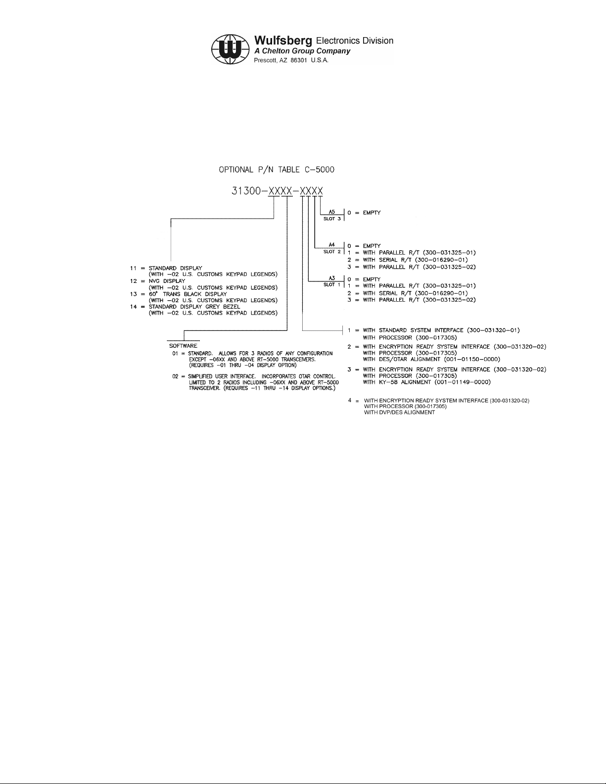
D. Part Numbering
The C-5000's basic unit part number 31300-XXXX-XXXX is configured as follows:
Figure 1-1. C-5000 Part Numbering
Note: Processor board PN 300-031315 can only be used with Parallel R/T board
PN 300-031325. Processor board PN 300-017305 can be used with Parallel
R/T PN 300-031325 and Serial R/T board PN 300-016290.
The installation and operation of the Frequency Agile C-5000 Control Unit is
limited to aircraft installations per FCC Rules and Regulations, Part 90, Section
90.423 and 90.203(h). A non-frequency agile C-5000 is available for other than
aircraft installations and is in compliance with FCC Rules and Regulations
90.203(g).
Page 1-4 Publication No. 150-041118
Section 1 - Introduction Rev A
Sep 2001

C-5000 COMMUNICATION MANAGEMENT CONTROLLER
INSTALLATION MANUAL
Table 1-1. RT-5000 Part Numbers
Part Number RT-5000 Description
400-015525-0101 Transceiver, No Guard Receiver
400-015525-0201 Transceiver, Crystal Controlled Guard Receiver, 30MHz -50MHz
400-015525-0301 Transceiver, Crystal Controlled Guard Receiver, 138 MHz - 174 MHz
400-015525-0401 Transceiver, Crystal Controlled Guard Receiver, 406 MHz - 512 MHz
400-015525-0501 Transceiver, Synthesized Guard
400-015525-0611 Transceiver, D.E.S. Encrypted VHF 138-174 MHz MTM Guard Receiver
400-015525-0711 Transceiver, VHF 138 MHz MTM Guard Receiver
400-015525-0811 Transceiver, D.E.S. Encrypted UHF403 MHz MTM Guard Receiver
400-015525-0911 Transceiver, UHF403 MHz MTM Guard Receiver
400-015525-1011 Transceiver, D.E.S. Encrypted UHF450-520 MHz MTM Guard Receiver
400-015525-1111 Transceiver, UHF520 MHz MTM Guard Receiver
400-015525-1211 Transceiver, D.E.S. Encrypted UHF800 Trunk MHz MTM Guard Receiver
400-015525-1311 Transceiver, UHF800 MHz MTM Guard Receiver
400-015525-1411 Transceiver, D.E.S. Encrypted VHF138 MHz MTM Guard Receiver and
UHF800 MHz MTM Guard Receiver
400-015525-1511 Transceiver, VHF138 MHz MTM Guard Receiver and UHF800 MHz MTM
Guard Receiver
400-015525-1611 Transceiver, D.E.S. Encrypted VHF138 MHz MTM Guard Receiver and D.E.S.
Encrypted UHF800 MHz MTM Guard Receiver
400-015525-1711 Transceiver, VHF138 MHz MTM Guard Receiver and D.E.S. Encrypted
UHF800 MHz MTM Guard Receiver
400-015525-1811 Transceiver, D.E.S. Encrypted VHF138 MHz MTM Guard Receiver and
UHF520 MHz MTM Guard Receiver
400-015525-1911 Transceiver, VHF138 MHz MTM Guard Receiver and UHF520 MHz MTM
Guard Receiver
400-015525-2011 Transceiver, D.E.S. Encrypted VHF138 MHz MTM Guard Receiver and D.E.S.
Encrypted UHF520 MHz MTM Guard Receiver
400-015525-2111 Transceiver, VHF138 MHz MTM Guard Receiver and D.E.S. Encrypted
UHF520 MHz MTM Guard Receiver
400-015525-2211 Transceiver, D.E.S. Encrypted VHF138 MHz MTM Guard Receiver and
UHF403 MHz MTM Guard Receiver
continues…
Publication No. 150-041118 Page 1-5
Rev A Section 1 - Introduction
Sep 2001

C-5000 COMMUNICATION MANAGEMENT CONTROLLER
INSTALLATION MANUAL
Table 1-1. RT-5000 Part Numbers (cont’d)
Part Number RT-5000 Description
400-015525-2311 Transceiver, VHF138 MHz MTM Guard Receiver and UHF403 MHz MTM
Guard Receiver
400-015525-2411 Transceiver, D.E.S. Encrypted VHF138 MHz MTM Guard Receiver and D.E.S.
Encrypted UHF403 MHz MTM Guard Receiver
400-015525-2511 Transceiver, VHF138 MHz MTM Guard Receiver and D.E.S. Encrypted
UHF403 MHz MTM Guard Receiver
400-015525-2611 Transceiver, DVI-XL UHF520 MHz MTM Guard Receiver
400-015525-2711 Transceiver, DVI-XL UHF800 MHz MTM Guard Receiver
Table 1-2. FLEXCOMM II Antenna Part Numbers
Part Number Antenna Description
121-040130-01 AT-560 -- 29.7 - 960 MHz 9.5” Tuned Multiband White
121-040130-02 AT-560 -- 29.7 - 960 MHz 9.5” Tuned Multiband Black
121-040129-01 AT-160 -- 29.7 – 960 MHz 9.5” Passive Multiband
121-040045-01 AT-5000 -- 29.7 – 960 MHz 5.5” (FC-5000 Req) White
121-040045-02 AT-5000 -- 29.7 – 960 MHz 5.5” (FC-5000 Req) Black
121-017850-01 AT-550 -- 29.7 – 960 MHz (FC-550 Req) White
153-017822-01 AT-150 -- 29.7 – 960 MHz (poor 30-88 MHz) White
121-016587-01 AT-50 -- 29.7 - 400MHz Autotuned Blade White
121-016796-01 AT-51 -- 29.7 - 400MHz Autotuned Blade White
121-016584-01 AT-140 -- 29.7MHz - 400MHz Blade White
121-016821-01 AT-400 -- 400MHz - 960MHZ Jet Blade White
153-016586-01 FC-50 Logic Converter -- Antenna Tuner for AT-50/51
153-040047-01 FC-5000 -- Antenna Tuner for AT-5000 and AT-560
153-017851 FC-550 Logic Converter
146-016958-01 Gasket, AT-400
146-014960-01 Gasket, AT-51
146-014959-01 Gasket, AT-50
Page 1-6 Publication No. 150-041118
Section 1 - Introduction Rev A
Sep 2001

C-5000 COMMUNICATION MANAGEMENT CONTROLLER
INSTALLATION MANUAL
Table 1-3. RT-30 Part Numbers
Part Number RT-30 Description
400-0098-000 Transceiver, FLEXCOMM Lo Band VHF, 29.70-49.99 MHz.
400-0098-001 Transceiver, FLEXCOMM Lo Band VHF, 29.70 - 49.99 MHz, with Guard
Receiver
400-0098-002 Transceiver, FLEXCOMM Lo Band VHF, 29.70 - 49.99 MHz, with Guard
Receiver and Guard Receiver CTCSS Tones.
Table 1-4. RT-118 Part Numbers
Part Number RT-118 Description
400-0119-000 Transceiver, FLEXCOMM VHF-AM Band 118.000 - 137.975 MHz,
Standard Receiver IF Bandwidth
400-0119-001 Transceiver, FLEXCOMM VHF-AM Band 118.000 - 137.975 MHz,
Wide Receiver IF Bandwidth
Table 1-5. RT-138 Part Numbers
Part Number RT-138 Description
400-0102-000 Transceiver, FLEXCOMM Hi Band VHF, 138.0000 - 173.9975 MHz
400-0102-001 Transceiver, FLEXCOMM Hi Band VHF, 138.0000 - 173.9975 MHz, with
Guard Receiver.
400-0102-002 Transceiver, FLEXCOMM Hi Band VHF, 138.0000 - 173.9975 MHz, with
Guard Receiver and Guard Receiver CTCSS Tones
400-0102-003 Transceiver, FLEXCOMM Hi Band VHF, 138.0000 - 173.9975 MHz, with
increased sensitivity (precludes Guard).
Publication No. 150-041118 Page 1-7
Rev A Section 1 - Introduction
Sep 2001

C-5000 COMMUNICATION MANAGEMENT CONTROLLER
INSTALLATION MANUAL
Table 1-6. RT-138F Part Numbers
Part Number RT-138F Description
400-014525-00 Transceiver, FLEXCOMM Hi Band VHF, 138.0000-173.9975 MHz.
400-014525-01 Transceiver, FLEXCOMM Hi Band VHF, 138.0000 - 173.9975 MHz, with
Guard Receiver.
400-014525-02 Transceiver, FLEXCOMM Hi Band VHF, 138.0000 - 173.9975MHz, with Guard
Receiver and Guard Receiver CTCSS Tones.
400-014525-03 Transceiver, FLEXCOMM Hi Band VHF, 138.0000 - 173.9975 MHz, with
increased sensitivity (precludes Guard).
400-014525-50 Transceiver, FLEXCOMM Hi Band VHF, 138.0000 - 173.9975 MHz, Voice
Encryption interface compatible.
400-014525-51 Transceiver, FLEXCOMM Hi Band VHF, 138.0000 - 173.9975 MHz, with
Guard Receiver, Voice Encryption interface compatible.
400-014525-52 Transceiver, FLEXCOMM Hi Band VHF, 138.0000 - 173.9975 MHz, with
Guard Receiver, Guard Receiver CTCSS Tones and Voice Encryption
interface compatible.
400-014525-53 Transceiver, FLEXCOMM Hi Band VHF, 138.0000 - 173.9975 MHz, with
increased sensitivity and Voice Encryption interface compatible (precludes
Guard).
Note: All RT-138F units are compatible with Voice Encryption systems utilizing Non Return to
Zero (NRZ) modulation at a data rate of 12 Kbit/sec or less. The -5X units are
specifically wired to readi l y interfac e with Motorola and General Electric encr ypti on
modules. Additionally, all RT-138F units are compatible with Digital Coded Squelch
Systems (Motorola Digital Private Line and GE Digital Channel Guard).
Page 1-8 Publication No. 150-041118
Section 1 - Introduction Rev A
Sep 2001

C-5000 COMMUNICATION MANAGEMENT CONTROLLER
INSTALLATION MANUAL
Table 1-7. RT-406F Part Numbers
Part Number RT-406F Description
400-012785-00 Transceiver, FLEXCOMM UHF Band, 406.0000 511.9875 MHz.
400-012785-01 Transceiver, FLEXCOMM UHF Band, 406-0000 511.9875 MHz, with Guard
Receiver.
400-012785-02 Transceiver, FLEXCOMM UHF Band, 406.0000 511.9875 MHz, with Guard
Receiver and Guard Receiver CTCSS Tones.
400-012785-03 Transceiver, FLEXCOMM UHF Band, 406.0000 511.9875 MHz, with increased
sensitivity (precludes Guard).
400-012785-50 Transceiver, FLEXCOMM UHF Band, 406.0000 511.9875 MHz, Voice
Encryption interface compatible
400-012785-51 Transceiver, FLEXCOMM UHF Band, 406.0000 511.9875 MHz, with Guard
Receiver, Voice Encryption interface compatible
400-012785-52 Transceiver, FLEXCOMM UHF Band, 406.0000 511.9875 MHz, with Guard
Receiver, Guard Receiver CTCSS Tones and Voice Encryption interface
compatible
400-012785-53 Transceiver, FLEXCOMM UHF Band, 406.0000 511.9875 MHz, with increased
sensitivity and Voice Encryption interface compatible (precludes Guard).
Note: All RT-406F units are compatible with Voice Encryption systems utilizing Non Return to
Zero (NRZ) modulation at a data rate of 12 Kbit/sec or less. The -5X units are
specifically wired to readi l y interfac e with Motorola and General Electric encr ypti on
modules. Additionally, all RT-406F units are compatible with Digital Coded Squelch
Systems (Motorola Digital Private Line and GE Digital Channel Guard).
Table 1-8. RT-450 Part Numbers
Part Number RT-450 Description
400-0103-000 Transceiver, FLEXCOMM UHF Band, 450.0000 - 469.9875 MHz.
400-0103-001 Transceiver, FLEXCOMM UHF Band, 450.0000 - 469.9875 MHz, with Guard
Receiver.
400-0103-002 Transceiver, FLEXCOMM UHF Band, 450.0000 - 469.9875 MHz, with Guard
Receiver and Guard Receiver CTCSS Tones.
400-0103-003 Transceiver, FLEXCOMM UHF Band, 450.0000 - 469.9875 MHz, with
increased sensitivity (precludes Guard).
Publication No. 150-041118 Page 1-9
Rev A Section 1 - Introduction
Sep 2001

C-5000 COMMUNICATION MANAGEMENT CONTROLLER
INSTALLATION MANUAL
Table 1-9. RT-7200 Part Numbers
Part Number RT-7200 Description
400-0087-000 Transceiver, RT-7200 VHF HI-Band, 138 .00 00 - 173 .99 5 MHz, 14/ 28 VDC,
100mW Audio, Recessed Connector.
400-0087-001 Transceiver, RT-7200 VHF HI-Band, 138.00 - 173.995 MHz, 14/28 VDC,
100mW Audio, Recessed Connector, with Guard Receiver.
400-0087-002 Transceiver, RT-7200 VHF HI-Band, 138 .00 00 - 173 .99 5 MHz, 14/ 28 VDC,
100mW Audio, Recessed Connector, with CTCSS Tones.
400-0087-003 Transceiver, RT-7200 VHF HI-Band, 138 .00 00 - 173 .99 5 MHz, 14/ 28 VDC,
100mW Audio, Recessed Connector, with Guard Receiver and CTCSS Tones.
Table 1-10. RT-9600 Part Numbers
Part Number RT-9600 Description
400-0052-002 Transceiver, RT-9600 VHF HI-Band, 150.0000 - 173.995 MHz, 14/28 VDC,
100 mW Audio, Protruding Connector
400-0052-005 Transceiver, RT-9600 VHF HI-Band, 150.0000 - 173.995 MHz, 14/28 VDC,
100 mW Audio, Protruding Connector, with Guard Receiver
400-0052-008 Transceiver, RT-9600 VHF HI-Band, 150.0000 - 173.995 MHz, 4/28 VDC,
100 mW Audio, Protruding Connector with CTCSS Tones
400-0052-011 Transceiver, RT-9600 VHF HI-Band, 150 .00 00 - 173 .99 5 MHz, 14/ 28 VDC,
100 mW Audio, Protruding Connector, with Guard Receiver and CTCSS Tones
400-0052-024 Transceiver, RT-9600 VHF HI-Band, 150.0000 - 173.995 MHz, 14/28VDC,
100 mW Audio, Recessed Connector
400-0052-025 Transceiver, RT-9600 VHF HI-Band, 150 .00 00 - 173 .99 5 MHz, 14/ 28 VDC,
100 mW Audio, Recessed Connector, with Guard Receiver
400-0052-026 Transceiver, RT-9600 VHF HI-Band, 150 .00 00 - 173 .99 5 MHz, 14/ 28 VDC,
100 mW Audio, Recessed Connector, with CTCSS Tones
400-0052-027 Transceiver, RT-9600 VHF HI-Band, 150 .00 00 - 173 .99 5 MHz, 14/ 28 VDC,
100 mW Audio, Recessed Connector, with Guard Receiver and CTCSS Tones
Page 1-10 Publication No. 150-041118
Section 1 - Introduction Rev A
Sep 2001

C-5000 COMMUNICATION MANAGEMENT CONTROLLER
INSTALLATION MANUAL
Table 1-11. RT-9600F Part Numbers
Part Number RT-9600F Description
400-0140-002 Transceiver, RT-9600F VHF HI-Ba nd, 150 .00 00 - 173.995 MH z, 14/2 8 VDC,
100 mW Audio, Protruding Connector
400-0140-005 Transceiver, RT-9600F VHF HI-Ba nd, 150 .00 00 - 173.995 MH z, 14/2 8 VDC,
100 mW Audio, Protruding Connector, with Guard Receiver
400-0140-008 Transceiver, RT-9600F VHF HI-Ba nd, 150 .00 00 - 173.995 MH z, 14/2 8 VDC,
100 mW Audio, Protruding Connector with CTCSS Tones
400-0140-011 Transceiver, RT-9600F VHF HI-Band, 14/ 28 VDC, 100 mW Audio, Protruding
Connector, with Guard Receiver and CTCSS Tones
400-0140-024 Transceiver, RT-9600F VHF HI-Band, 150.0000 - 173.995 MHz, 14/28VDC,
100 mW Audio, Recessed Connector
400-0140-025 Transceiver, RT-9600F VHF HI-Ba nd, 150 .00 00 - 173.995 MH z, 14/2 8 VDC,
100 mW Audio, Recessed Connector, with Guard Receiver
400-0140-026 Transceiver, RT-9600F VHF HI-Ba nd, 150 .00 00 - 173.995 MH z, 14/2 8 VDC,
100 mW Audio, Recessed Connector, with CTCSS Tones
400-0140-027 Transceiver, RT-9600F VHF HI-Ba nd, 150 .00 00 - 173.995 MH z, 14/2 8 VDC,
100 mW Audio, Recessed Connector, with Guard Receiver and CTCSS Tones
040-0140-052,
400-0140-152
400-0140-055,
400-0140-155
400-0140-058,
400-0140-158
400-0140-061,
400-0140-1611
400-0140-074,
400-0140-174
400-0140-075,
400-0140-175
Transceiver, RT-9600F VHF HI-Band, 150.0000 -173.995 MHz, 14/28 VDC,
100 mW Audio, Protruding Connector and Voice Encryption interface
compatible
Transceiver, RT-9600F VHF HI-Ba nd, 150 .00 00 - 173.995 MHz, 14/28 VDC,
100 mW Audio, Protruding Connector, and Voice Encryption interface
compatible
Transceiver, RT-9600F VHF HI-Band, 150.0000 - 173.995 MHz, 14/28 VDC,
100 mW Audio, Protruding Connector with CTCSS Tones, and Voice
Encryption interface compatible
Transceiver, RT-9600F VHF HI-Ba nd, 150 .00 00 - 173.995 MHz, 14/28 VDC,
100 mW Audio, Protruding Connector, with Guard Receiver and CTCSS
Tones, and Voice Encryption interface compatible
Transceiver, RT-9600F VHF HI-Ba nd, 150 .000 0 - 173.995 MHz, 14/28 VDC,
100 mW Audio, Recessed Connector, and Voice Encryption interface
compatible
Transceiver, RT-9600F VHF HI-Band, 150.0000 - 173.995 MHz, 14/28 VDC,
100 mW Audio, Recessed Connector, with Guard Receiver, and Voice
Encryption interface compatible
continues…
Publication No. 150-041118 Page 1-11
Rev A Section 1 - Introduction
Sep 2001

C-5000 COMMUNICATION MANAGEMENT CONTROLLER
INSTALLATION MANUAL
Table 1-11. RT-9600F Part Numbers (Cont’d)
Part Number RT-9600F Description
400-0140-076,
400-0140-176
400-0140-077,
400-0140-177
Note: All RT-9600F units are compatible with Voice Encryption systems utilizing Non Return to
Zero (NRZ) modulation at a data rate of 12 Kbit/sec or less. The -05X, -06X, and -07X
units are specifically wired to readily interface with Motorola encryption modules.
Additionally, all RT-9600F units are compatible with Digital Coded Squelch Systems
(Motorola Digital Private Line and GE Digital Channel Guard).
Transceiver, RT-9600F VHF HI-Band, 150.0000 - 173.995 MHz, 14/28 VDC,
100 mW Audio, Recessed Connector, with CTCSS Tones, and Voice
Encryption interface compatible
Transceiver, RT-9600F VHF HI-Ba nd, 150 .00 00 - 173.995 MHz, 14/28 VDC,
100 mW Audio, Recessed Connector, with Guard Receiver and CTCSS
Tones, and Voice Encryption interface compatible
Page 1-12 Publication No. 150-041118
Section 1 - Introduction Rev A
Sep 2001
C-5000 COMMUNICATION MANAGEMENT CONTROLLER
INSTALLATION MANUAL
SECTION 2 - SYSTEM INSTALLATION
1. General
This section contains system specifications, interface information, and examples of typical system
configurations for the C-5000 Communication Management Controller installed with FLEXCOMM
II, FLEXCOMM I, or a configuration consisting of both FLEXCOMM II and FLEXCOMM I
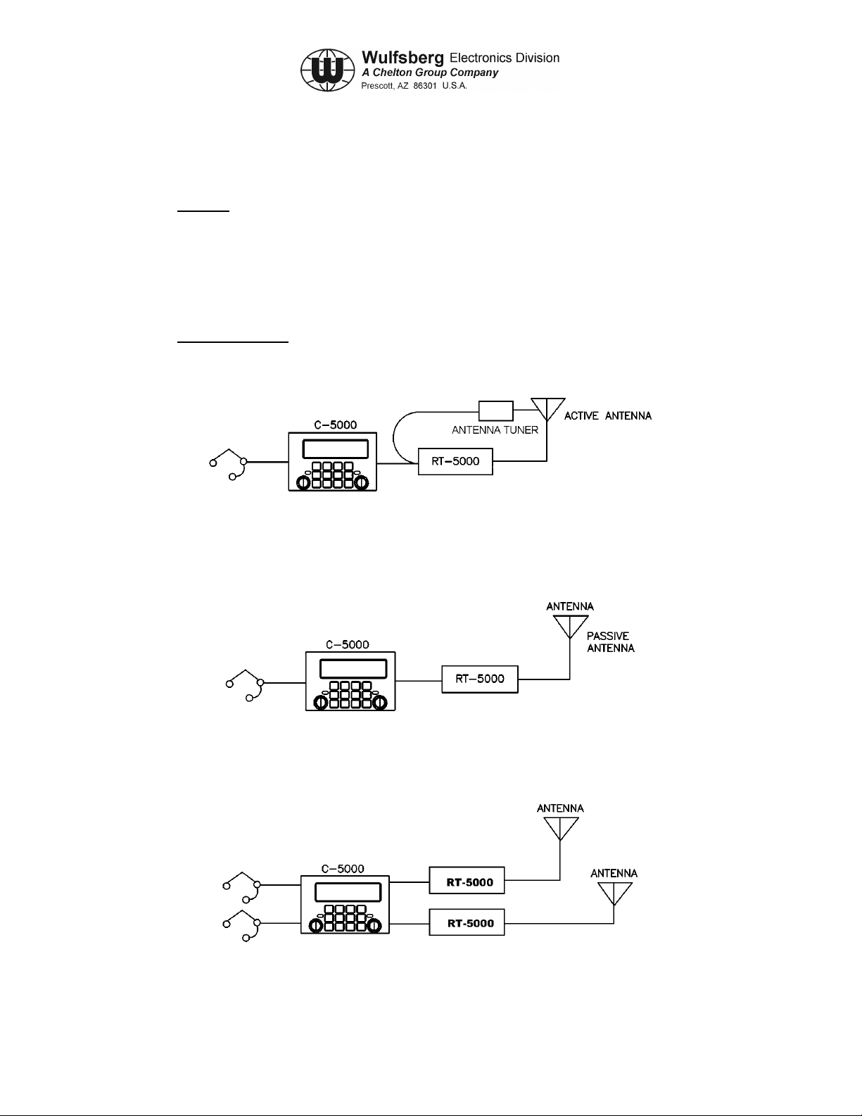
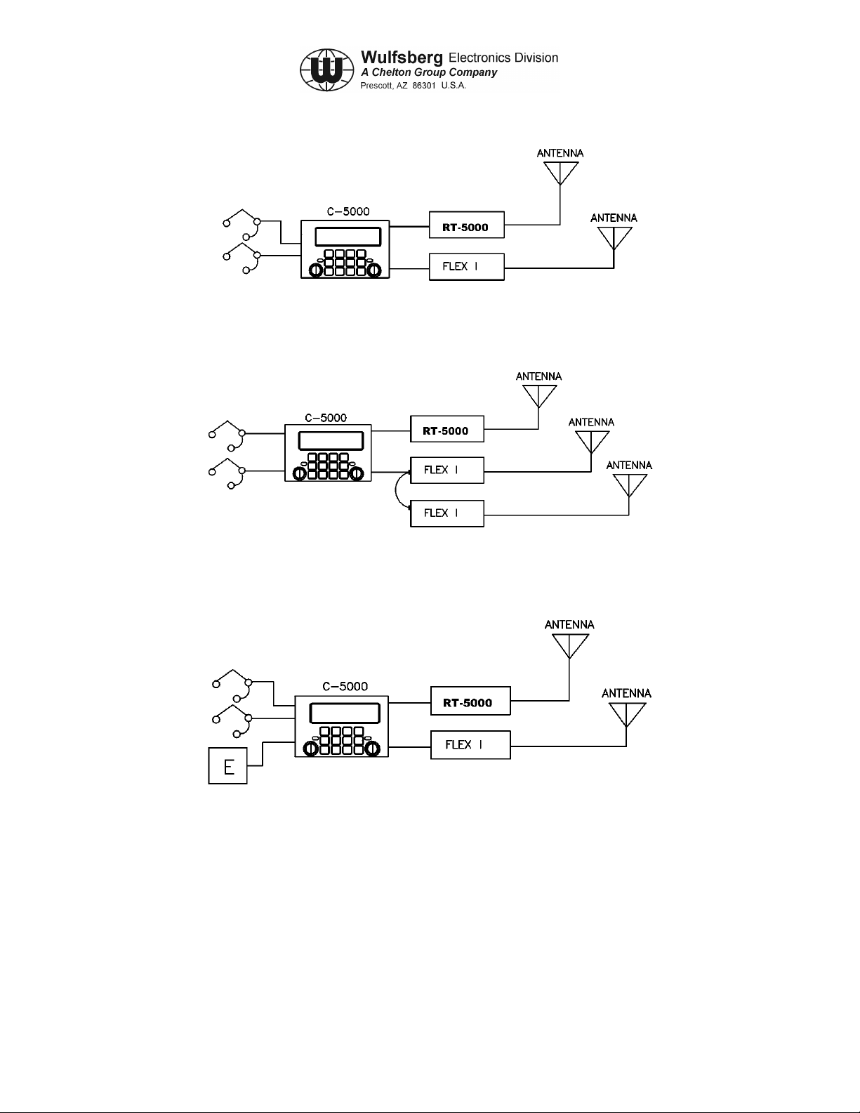
transceivers. System power requirements are included in Table 2-1. Figures 2-1 through 2- 6
show generalized system interface diagrams.
2. Sample Systems
The following are examples of ways to configure your aircraft installation:
Figure 2-1. Single RT-5000 with Active Antenna
Figure 2-2. Single RT-5000 with Passive Antenna
ACTIVE OR PASSIVE
ANTENNA
ACTIVE OR PASSIVE
ANTENNA
Figure 2-3. Dual RT-5000 with Dual Mic/Headset
Publication No. 150-041118 Page 2-1
Rev A Section 2 – System Installation
Sep 2001
C-5000 COMMUNICATION MANAGEMENT CONTROLLER
INSTALLATION MANUAL
Figure 2-4. Dual Transceiver, RT-5000 and Flexcomm I
Figure 2-5. Dual Transceiver, RT-5000 and Parallel Flexcomm I Transceivers
Figure 2-6. Dual Transceiver with External Encryption
Page 2-2 Publication No. 150-041118
Section 2 – System Installation Rev A
Sep 2001

C-5000 COMMUNICATION MANAGEMENT CONTROLLER
INSTALLATION MANUAL
3. Component Specifications
COMPONENT POWER REQUIREMENTS
C-5000 VOLTAGE: 27.5 Vdc ± 20% Aircraft
CURRENT: 0.4 amps (typical)
1.3 amps (maximum external loading)
FLEXCOMM II
RT-5000
FLEXCOMM I RT-30
VOLTAGE: 27.5 VDC Aircraft
STANDBY: 1.7 amps
RECEIVE: 1.7 amps
TRANSMIT: 10.0 amps
Refer to FLEXCOMM I Transceiver System Installation
RT-118
RT-138
RT-138F
RT-406F
RT-450
RT-9600
RT-9600F
RT-7200
Manual, Manual Number 150-040011, for power
requirements.
Refer to VHF/FM Transceivers RT-7200, RT-9600,
AN/ARC-513(V) Installat ion /Oper at ors Manua l, Manual
Number 150-0061-000, for power requirements.
Table 2-1. System Power Requirements
A. C-5000 Communication Management Controller
Note: The installation and operation of the Frequency Agile C-5000 Control Unit is limited
to aircraft installations per FCC Rules and Regulations, Part 90, Section 90.423 and
90.203(h). A non-frequency agile C-5000 is available for other than aircraft
installations and is in compliance with FCC Rules and Regulations 90.203(g).
(1) Number of Channels: 350 programmable channels
(2) Temperature: -30° to + 60° C
(3) Panel Lighting: 5 Vdc, 5 Vac, or 28 Vdc
(4) Keypad Lighting: Type: Electro Luminescent (E.L.) Lighting
Color: Blue/white (standard)
Green NVG (optional
Publication No. 150-041118 Page 2-3
Rev A Section 2 – System Installation
Sep 2001

C-5000 COMMUNICATION MANAGEMENT CONTROLLER
INSTALLATION MANUAL
(5) Audio Output: Standard: 100 mV into 600 ohm load, shop adjustable
0.1 to 250 mW, 600 ohms
Unsquelched Audio: 0.5 VRMS/2k ohms, adjustable 0.1
to 1.5 V
(6) Audio Input Level: Std. Voice: 0.25 Vrms 150 ohm balanced pair, shop
adjustable 30 mV to 1.5 Vrms Narrowband: same as
voice, 2K single ended
(7) Microphone Interface: Carbon or equivalent
B. FLEXCOMM II (RT-5000)
(1) RT-5000 Transceiver
a) Tunability: 1.25 kHz Incremental Tuning Simplex/Semi-duplex.
b) Mode: FM/AM/P25/Trunking
c) Frequency Bands: 29.7-88 MHz (FM Band)
108-116 MHz (receive onl y)
118-156 MHz (AM Band)
138-174 MHz (FM Band)
220-225 MHz (AM/FM)
225-400 MHz (AM/FM)
FM:
403-512 MHz
512-806 MHz
806-960 MHz
d) Channeling: 12.5/20/25/30/50 kHz
e) Temperature: -30° C to + 60° C
f) Altitude: 51,000 feet above MSL
g) Control: C-5000 Serial Tuning Bus
h) Tx Power: 10 Watts FM/P25
15 Watts AM
Page 2-4 Publication No. 150-041118
Section 2 – System Installation Rev A
Sep 2001

C-5000 COMMUNICATION MANAGEMENT CONTROLLER
C. RT-5000 Antennas
1) AT-560 Antenna
1) Frequency: 29.7 - 960 MHz
2) VSWR: 2.5:1 maximum
3) Radiation Pattern: Omnidir ec t ion al in a zimuth
4) Polarization: Vertical
5) Impedance: 50 ohms
6) Power: 20 Watts
7) Gain: 30 MHz, -14 dBi
INSTALLATION MANUAL
88 MHz, -6 dBi
108-174 MHz, 0 dBi
220-960 MHz, 0 dBi
8) Temperature: -55°C to + 70°C
9) Altitude: 40,000 feet
2) AT-160 Antenna
1) Frequency: 29.7 - 960 MHz
2) VSWR: 2.5:1 maximum
3) Radiation Pattern: Omnidir ec t ion al in a zimuth
4) Polarization: Vertical
5) Impedance: 50 ohms
6) Power: 20 Watts
7) Gain: 30 MHz, -21 dBi
60 MHz, -21 dBi
88 MHz, -12 dBi
108-174 MHz, -3 dBi
225-960 MHz, 0 dBi
8) Temperature: -55°C to + 70°C
9) Altitude: 40,000 feet
3) AT-5000 Antenna
Publication No. 150-041118 Page 2-5
Rev A Section 2 – System Installation
Sep 2001

C-5000 COMMUNICATION MANAGEMENT CONTROLLER
INSTALLATION MANUAL
1) Frequency: 29.7 - 960 MHz
2) VSWR: 2.5:1 maximum
3) Radiation Pattern: Omnidir ec t ion al in a zimuth
4) Polarization: Vertical
5) Impedance: 50 ohms
6) Power: 20 Watts
7) Gain: 30 MHz, -15 dBi
88 MHz, -7.5 dBi
118-174 MHz, -3 dBi
225-960 MHz, 0 dBi
8) Temperature: -55°C to + 70°C
9) Altitude: 55,000 feet
4) AT-550 Antenna
1) Frequency: 29.7 - 960 MHz
2) VSWR: 2.5:1 maximum
3) Radiation Pattern: Omnidir ec t ion al in a zimuth
4) Polarization: Vertical
5) Impedance: 50 ohms
6) Power: 20 Watts
7) Gain: 30 MHz, -14 dBi
88 MHz, -6 dBi
108-174 MHz, 0 dBi
225-960 MHz, 0 dBi
8) Temperature: -55°C to + 70°C
9) Altitude: 40,000 feet
Page 2-6 Publication No. 150-041118
Section 2 – System Installation Rev A
Sep 2001

C-5000 COMMUNICATION MANAGEMENT CONTROLLER
INSTALLATION MANUAL
5) AT-50 Antenna
1) Frequency: 29.7 - 400 MHz
2) VSWR: 2: 1 maximum
3) Radiation Pattern: Omnidir ec t ion al in a zimuth
4) Polarization: Vertical
5) Impedance: 50 ohms
6) Power: 20 Watts
7) Gain: 30 MHz, -11 dBi
88 MHz, -6 dBi
108-174 MHz, 0 dBi
225-400 MHz, + 2 dBi
8) Temperature: -54°C to + 71°C
9) Altitude: 50,000 feet
6) AT-51 Antenna
1) Frequency: 29.7 - 400 MHz
2) VSWR: 2.5: 1 maximum
3) Radiation Pattern: Omnidir ec t ion al in a zimuth
4) Polarization: Vertical
5) Impedance: 50 Ohms
6) Power: 15 Watts
7) Gain: 30 MHz, -14 dBi
88 MHz, -7 dBi
108-174 MHz, -3 dBi
225-400 MHz, 0 dB
8) Temperature: -54°C to + 71°C
9) Altitude: 50,000 feet
Publication No. 150-041118 Page 2-7
Rev A Section 2 – System Installation
Sep 2001

C-5000 COMMUNICATION MANAGEMENT CONTROLLER
INSTALLATION MANUAL
7) AT-140 Antenna
1) Frequency: 29.7 - 400 MHz
2) VSWR: 2.5: 1 at 30-88 MHz
5.0: 1 at 108-117 MHz
2.5: 1 at 118-174 MHz
2.0: 1 at 225-400 MHz
3) Radiation Pattern: Omnidir ec t ion al in a zimuth
4) Polarization: Vertical
5) Impedance: 50 ohms
6) Power: 50 Watts
7) Gain: 30 MHz -22.5 dBi
88 MHz -10 dBi
108 - 174 MHz -2 dBi
225 - 400 MHz +2 dBi
8) Temperature: -54°C to + 71°C operating
-62°C to + 85°C non-operating
9) Altitude: 50,000 ft
8) AT-400 Antenna.
1) Frequency: 400 - 960 MHz
2) VSWR: 2.0: 1 maximum
3) Radiation Pattern: Typical of λ/4 stub
4) Polarization: Vertical
5) Impedance: 50 ohms
6) RF Power: 100 Watts
7) Efficiency: 90% min. 400 - 960 MHz
8) Temperature: -55°C to +70°C
9) Altitude: 50,000 ft
Page 2-8 Publication No. 150-041118
Section 2 – System Installation Rev A
Sep 2001

C-5000 COMMUNICATION MANAGEMENT CONTROLLER
INSTALLATION MANUAL
D. FLEXCOMM I
Note: Refer to FLEXCOMM I Transceiver System Installation Manual, Manual Number
150-040011, for specification data on FLEXCOMM Transceivers and Antennas.
Refer to VHF/FM Transceivers RT-7200, RT-9600, AN/ARC-513(V) Installation
/Operators Manual, Manual Number 150-0061-000, for specification data on
RT-9600 and RT-7200 transceivers.
Publication No. 150-041118 Page 2-9
Rev A Section 2 – System Installation
Sep 2001

C-5000 COMMUNICATION MANAGEMENT CONTROLLER
INSTALLATION MANUAL
This page intentionall y left blank.
Page 2-10 Publication No. 150-041118
Section 2 – System Installation Rev A
Sep 2001

C-5000 COMMUNICATION MANAGEMENT CONTROLLER
INSTALLATION MANUAL
SECTION 3 - MECHANICAL INSTALLATION
1. General
This section contains instructions and considerations for the proper mechanical installation of the
C-5000 Communication Management Controller with FLEXCOMM II and FLEXCOMM I Systems.
The information presented here is necessary for the proper operation and satisfactory
performance of the equipment.
The FLEXCOMM II System consists of the RT-5000 Transceiver, appropriate antennas, and
optional equipment as required.
The FLEXCOMM I System consists of an RT-9600F, or an RT-9600, or an RT-7200, or a
combination of up to 3 of the following transceivers: RT-30, RT-118, RT-138, RT-138F, RT-406F,
RT-450, appropriate antenna(s), and optional equipment as required.
Note: An RT-138 transceiver or an RT-138F transceiver (not both) may be installed in the
same RT-System. An RT-406F transceiver or an RT-450 transceiver (not both) may be
installed in the same RT System.
Refer to FLEXCOMM I Transceiver System Installation Manual, Manual Number 150040011, for mechanical installation information on FLEXCOMM transceivers. Refer to
VHF/FM Transceivers RT-7200, RT-9600, AN/ARC-513(V) Installation /Operators
Manual, Manual Number 150-0061-000, for mechanical installation information on the
RT-9600, and RT-7200 transceivers.
For instructions and considerations on the mechanical installation of a configuration that consists
of both FLEXCOMM II and FLEXCOMM I transceivers, refer to applicable information in this
section for the installation of FLEXCOMM II transceivers, and to the documents noted in the
previous paragraph for installation of FLEXCOMM I transceivers.
2. Unpacking and Inspecting Equipment
Physically compare the presence of each item in the shipment with that shown on the packing list.
Exercise care when unpacking each unit. Make a visual inspection of each unit for evidence of
damage incurred during shipment. If a claim for damage is to be made, save the shipping
container to substantiate the claim. When all equipment is unpacked, it is suggested the carton
and packing materials be saved for possible reshipment.
Publication No. 150-041118 Page 3-1
Rev A Section 3 – Mechanical Installation
Sep 2001

C-5000 COMMUNICATION MANAGEMENT CONTROLLER
INSTALLATION MANUAL
3. General Installation Requirements
A. Component Weights
Component Weight
C-5000 3.1 to 3.9 lbs (1.4 to1.8 kg) depending on configuration
RT-5000 16.2 to 19.7 lbs (7.3 to 8.9 kg) depending on configuration
AT-560 2.7 lbs (1.2 kg)
AT-160 2.7 lbs (1.2 kg)
AT-5000 3.5 lbs (1.6 kg)
AT-550 2.7 lbs (1.2 kg)
AT-150 2.7 lbs (1.2 kg)
AT-50 4.8 lbs max (2.18 kg)
AT-51 3.1 lbs max (1.41 kg)
AT-140 4.0 lbs max (1.8 kg)
AT-400 .75 lbs max (.34 kg)
FC-50 1.65 lbs max (0.75 kg)
FC-5000 1.65 lbs (0.75 kg)
FC-550 1.75 lbs (0.79 kg)
HA-4 1.13 lbs (0.51 kg)
FLEXCOMM I
Components
Refer to appropriate Installation Manual
Table 3-1. Component Weights
Page 3-2 Publication No. 150-041118
Section 3 – Mechanical Installation Rev A
Sep 2001

C-5000 COMMUNICATION MANAGEMENT CONTROLLER
INSTALLATION MANUAL
4. Installation of Multipin Crimp Connectors
A. Contacts and Crimp Tool Information
Contacts, D-Sub, Min.
Crimp or Solder
Crimp Tools
(Suggested supplier:
Daniels Manufacturing
Corporation
526 Thorpe Road
Orlando, FL 32824)
Insertion/Removal Tool Positronic M81969/1-04 or equivalent
B. Contacts and Insertion/Removal Tool Manufacturer Name and Address:
Positronic Industries, Inc.
423 N. Campbell Ave.
PO Box 8247
Springfield, Missouri 65 801
WED PN 129-115451-01
Positronic PN FC8122D, crimp (or equivalent) or
Positronic FS8122D, solder (or equivalent)
C-5000 Serial RT Card interface Connector
Handle - M22520/2-01
Positioner - M22520/2-08
C-5000 Parallel RT Card Interface Connector
Handle - M22520/2-01
Positioner - M22520/2-06
RT-5000 Interface Connector
Tool Frame - M22520/1-01
Turret - M22520/1-02
Positioner - M22520/2-08
5. Installation of C-5000
Mount C-5000 on Dzus/rails per MIL MS-25213.
See Figure 3-1 for mounting dimensions.
6. Installation of RT-5000
The RT-5000 is designed for horizontal or vertical fixed tray mounting. However, vertical
mounting results in better cooling.
A minimum of 1 inch clearance is required on all
sides.
1. Firmly hand-tighten the rack knobs to secure the RT-5000 in the mounting tray. See
Figures 3-2 through 3-4 for mounting dimensions.
2. Attach antenna cabling [Connector J103 (N Type, less-than-or equal-to 400 MHz), and
J102 (TNC Type, greater-than-or-equal-to 400 MHz)]. Insure proper connector mating.
3. Attach RT-5000 mating Connector J101 (55 pin).
Publication No. 150-041118 Page 3-3
Rev A Section 3 – Mechanical Installation
Sep 2001

C-5000 COMMUNICATION MANAGEMENT CONTROLLER
INSTALLATION MANUAL
7. Installation of Antennas
The antenna should be mounted on the bottom of the aircraft if possible.
Unpainted aluminum base must make good electrical contact with airframe. Antenna should be
installed on flat surface.
A bead of sealant such as Dow Corning RTV-738 should be applied to the outside perimeter of
the mounting surface.
See Figures 3-5 through 3-15 for appropriate antenna mounting dimensions.
A. AT-560 and AT-5000
See the AT-560 and AT-5000 envelope drawings, Figures 3-5 and 3-7, for dimensions.
Mount antenna with No. 10 screws.
B. FC-5000
Note: The FC-5000 Logic Converter is required for the AT-560 and AT-5000 antennas.
See the FC-5000 envelope drawing, Figure 3-15, for dimensions.
C. AT-160 and AT-150
See the AT-160 and AT-150 envelope drawings, Figures 3-6 and 3-9, for dimensions.
Mount antenna with No. 10 screws.
D. AT-550
See the AT-550 envelope drawing, Figure 3-8, for dimensions.
Mount antenna with No. 10 screws.
D. FC-550
Note: The FC-550 Logic Converter is required for the AT-550 antenna.
See the FC-550 envelope drawing, Figure 3-16, for dimensions.
F. AT-50 and AT-51
If antenna is installed on top of aircraft, drainage holes at smaller end of antenna should be
plugged with blanking plugs and RTV. Drainage holes in antenna base flange at mounting
face should not be obstructed.
If antenna is installed on underside of aircraft, drainage holes at smaller end of antenna base
flange at mounting face should be sealed with a small fillet of RTV.
Page 3-4 Publication No. 150-041118
Section 3 – Mechanical Installation Rev A
Sep 2001

C-5000 COMMUNICATION MANAGEMENT CONTROLLER
INSTALLATION MANUAL
Note: For full 29.7-900 MHz frequency coverage, the user must also install the AT-400
antenna for 400-960 frequencies.
See the AT-50 and AT-51 envelope drawings, Figures 3-10 and 3-11, for dimensions.
Mount antenna with No. 10 screws.
G. FC-50
Note: The FC-50 Logic Converter is required for the AT-50 and AT-51 antennas.
See the FC-50 envelope drawing, Figure 3-14, for dimensions.
H. AT-400
See the AT-400 envelope drawing, Figure 3-13, for dimensions.
Mount antenna with No. 8 screws.
I. AT-140
Note: For full 29.7-400 MHz frequency coverage, the user must also install the AT-140
antenna for 400-960 frequencies.
See the AT-140 envelope drawing, Figure 3-12, for dimensions.
Mount antenna with No. 10 screws.
Publication No. 150-041118 Page 3-5
Rev A Section 3 – Mechanical Installation
Sep 2001

C-5000 COMMUNICATION MANAGEMENT CONTROLLER
INSTALLATION MANUAL
This page intentionall y left blank
.
Page 3-6 Publication No. 150-041118
Section 3 – Mechanical Installation Rev A
Sep 2001

C-5000 COMMUNICATION MANAGEMENT CONTROLLER
INSTALLATION MANUAL
Remove this page and insert:
154-031300, Sheet 1 of 1 (Figure 3-1)
154-015525, Sheet 1 of 1 (Figure 3-2)
300-316835, Sheet 1 of 1 (Figure 3-3)
300-316605, Sheet 1 of 1 (Figure 3-4)
121-040130, Sheet 1 of 1 (Figure 3-5)
121-040129, Sheet 1 of 1 (Figure 3-6)
121-040045, Sheet 1 of 1 (Figure 3-7)
121-017850, Sheet 1 of 1 (Figure 3-8)
153-017822, Sheet 1 of 1 (Figure 3-9)
121-016687, Sheet 1 of 1 (Figure 3-10)
121-016796, Sheet 1 of 1 (Figure 3-11)
121-016584, Sheet 1 of 1 (Figure 3-12)
121-016821, Sheet 1 of 1 (Figure 3-13)
153-016586, Sheet 1 of 1 (Figure 3-14)
153-040047, Sheet 1 of 1 (Figure 3-15)
153-017851, Sheet 1 of 1 (Figure 3-16)
Publication No. 150-041118 Page 3-7
Rev A Section 3 – Mechanical Installation
Sep 2001

Remove this page.
C-5000 COMMUNICATION MANAGEMENT CONTROLLER
INSTALLATION MANUAL
Page 3-8 Publication No. 150-041118
Section 3 – Mechanical Installation Rev A
Sep 2001

C-5000 COMMUNICATION MANAGEMENT CONTROLLER
INSTALLATION MANUAL
SECTION 4 - ELECTRICAL INSTALLATION
1. General
The following section describes the wiring requirements and options for the installation of the
system. Because the system has so many features and options, it is recommended that the
installer take the time to read pin descriptions and all notes on wiring diagrams before designing
an installation.
Figure 4-1 Rear View of C-5000
2. Wiring Considerations
To simplify the systems design, follow the steps below:
Step 1: Determine the type and number of radios. The C-5000 can control one or two
transceiver systems. The word system is used because a Flexcomm I installation can be
made of multiple transceivers electrically daisy chained to make one system. Based on the
type of radio, chose the part number of C-5000 that applies to your application.
Step 2: Determine the type of antenna. For each transceiver, determine the appropriate
antenna. For Flexcomm I transceivers, see the proper installation manuals for options. For
the RT-5000, the process begins by determining if the user needs optimum 30-88MHz
performance. If so, the recommended antenna system will be an “active” antenna (i.e. one
that is electrically tuned for maximum performance). If the user rarely uses 30-88 MHz, then
passive antenna is suggested. Passive antennas are less expensive and less complex to
install. Remember that performance in the 30-88 MHz frequency range is very degraded vs.
an active antenna.
Step 3: Microphone/Headset. If only one radio is installed, use the primary mic/headset
port. If two radios are installed, use primary mic/headset for transceiver system #1 and
secondary mic/headset for transceiver system #2. If only one mic/headset port is available
on the audio panel, use the primary mic/headset port and configure the C-5000 to operate in
“single mic mode”.
Publication No. 150-041118 Page 4-1
Rev A Section 4 –Electrical Installation
Sep 2001

C-5000 COMMUNICATION MANAGEMENT CONTROLLER
INSTALLATION MANUAL
Step 4: Panel Lighting. Select the input pin on P500 for the desired backlighting.
Options are 28 Vdc (pin 30) or 5 Vdc/5vrms (pin 8).
Step 5: System Wiring. Based on steps 1-5, choose the wiring diagrams from this
section that apply to your configuration. Note that if you have two RT-5000’s in your system,
copy the wiring illustrated for P501 to P502. In other words, choose the wiring for each radio
and apply it to the appropriate connector.
A. C-5000 System Interface Connector, P500 Wiring Considerations
(1) P500 Connector
Figure 4-2 P500 Connector
Page 4-2 Publication No. 150-041118
Section 4 – Electrical Insta lla tio n Rev A
Sep 2001

C-5000 COMMUNICATION MANAGEMENT CONTROLLER
INSTALLATION MANUAL
(2) System Interface Connector P500 Pin Names.
PIN SIGNAL NAME PIN SIGNAL NAME
1 RT-X REXMT AUDIO OUT 32 RESERVED SPARE C
2 RS-422 TX LO 33 RT-X SELECT B
3 XMT AUDIO IN HI 34 RT-X REXMT CONTROL KEY OUT
4 XMT AUDIO COMMON 35 PLAIN/CIPHER SEL
5 INTERNAL CIPHER SEL A 36 EXT. CIPHER ACTIVE
6 INTERNAL CIPHER SEL B 37 RT-X WB MN RCV AUDIO OUT
7 REXMT AUDIO IN 38 RCV'NG EXT ENCRYP TEXT
8 5V LITES 39 HEADSET AUDIO COMMON
9 PRIMARY CARBON MIC Hl 40 PRIMARY HEADSET AUDIO HI
10 SECONDARY CARBON MIC LO 41 SECONDARY MIC PTT
11 SHIELD 42 EXT RT-X DECODED RCV AUDIO
12 CIPHER/PLAIN SEL 43 A/C POWER GND
13 RT-X GUARD AUDIO 0UT 44 27.5 VDC A/C POWER
14 INTERNAL CIPHER DISABLE 45 RS-422 TX HI
15 PTT FROM EXT CIPHER 46 RS-422 RX1 HI
16 RT-X SELECT A 47 RS-422 RX1 LO
17 SECONDARY CARBON MIC HI 48 MIC OUT LO
18 PRIMARY MIC PTT 49 MIC OUT HI
19 XMT'NG EXT ENCRYP TEXT 50 28V LITES
20 SECONDARY HEADSET AUDIO HI 51 RESERVED SPARE E
21 RESERVED SPARE C 52 RESERVED SPARE G
22 SYSTEM (GRD) PRECEDENCE CHN IN 53 RESERVED SPARE A
23 BW CONTROL IN 54 RESERVED SPARE F
24 RS-422 RX2 HI 55 INTERNAL CIPHER SEL C
25 RS-422 RX2 LO 56 PTT TO CIPHER
26 ZEROIZE 57 SPARE B
27 AUX AUDIO IN HI 58 AUX -15VDC
28 AUX +5 VDC 59 SPARE A
29 PRIMARY CARBON MIC LO 60 AUX +15 VDC
30 LITES COMMON 61 EXT RT-X WB XMT AUDIO
31 RESERVED SPARE B 62 AUX GND
Table 4-1. System Interface Connector P500 Pin Names
Publication No. 150-041118 Page 4-3
Rev A Section 4 –Electrical Installation
Sep 2001

C-5000 COMMUNICATION MANAGEMENT CONTROLLER
INSTALLATION MANUAL
(3) Primary Carbon Mic HI/LO (Pins 9, 29)
These pins provide a 150 Ohm input impedance for the crew microphone input. Standard
Carbon Mic bias of 15V through 300 Ohm s is provided. Standard modulation of 1 kHz
tone at 0.25 Vrms is factory set for ± 3 kHz deviation although an adjust range of 30 mV
to 1.5 Vrms is provided by A2R174 on the system interface board.
(4) Primary Mic PTT (Pin 18)
This pin, when grounded, activates the transceiver system(s) selected for the primary
mic/headset interface.
Note: The primary mic LO and PTT should be connected together at the mic interface
(audio panel or mic jack). Alternately, the mic LO should be grounded at the mic
interface as mic bias is not provided unless mic LO is DC grounded.
(5) Primary Headset Audio HI/COMMON (Pins 39, 40)
The pins provide receive and sidetone audio output for the transceiver system(s) selected
for the primary mic/headset interface. Standard audio levels of 100 mW into 600 Ohm
load is provided for standard modulation although an adjustment range of 0.5 to 200 mW
is provided by A2R86 of the system interface board.
(6) Secondary Carbon Mic HI/LO, Secondary PTT, and Secondary Headset Audio (Pins
10, 17, 20, 41)
These pins provide a similar interface as the primary counterparts with some functional
exceptions. Although levels and impedances provided are the same, the secondary
interface provides the limited function of talk and listen in clear, non-encrypted audio.
Features provided by the primary interface i.e. Selectable audio routing through internal
or external encryption systems integrated with the C-5000 are not supported at the
secondary interface.
(7) Shield (Pin 11)
All shields of signals originating at the C-5000 and terminating at other equipment should
be connected to this pin and left unterminated at the other equipment. Similarly, the
shields of signals originating at other equipment and terminating at the C-5000 should be
grounded at the other equipment and left unterminated at the C-5000.
(8) 27.5 Vdc A/C Power and Ground (Pin 43, 44)
These pins provide aircraft 27.5 Vdc power to the C-5000 system. Typical loading is
approximately 350 mA, however with external loading by auxiliary equipment connected
to ±15 V and +5 V pins provided, the current requirement can be 1.3 Amp at 27.5 Vdc
and approach 2 Amps at low voltage. Appropriate circuit breaker should be provided with
consideration given to separately powered radio equipment as part of the basic
communications equipment being controlled b y the C-5000.
Page 4-4 Publication No. 150-041118
Section 4 – Electrical Insta lla tio n Rev A
Sep 2001

C-5000 COMMUNICATION MANAGEMENT CONTROLLER
INSTALLATION MANUAL
(9) 28V, 5V, Common Lites (Pins 8, 30, 50)
These pins provide for aircraft lite dimmer bus control of the keyboard lighting. Either
28 Vdc, 5 Vrms or 5 Vdc lighting may be used. The C-5000 does not draw power from
the buss but simply monitors the voltage for proper lite tracking. Only 5 V or 28 V may be
connected at once.
(10) RS-422 TX, RS-422 RX1, RS-422 RX2 HI/LO (Pins 2, 24, 25, 45, 46, 47)
These pins provide for a bi-directional digital data buss to other equipment on board the
aircraft. Two separate receive inputs are provided and the transmit pair may be
connected to multiple RS-422 devices. The receive shields should be connected only at
the originating equipment and the transmit shield should only be connected to the C-5000
shield pin.
(11) Internal Cipher Select A, B, C (Pins 5, 6, 55)
These pins are normally left unterminated and Internal Cipher Selection is managed from
the C-5000. Alternately, pins A, B, and C may be grounded in a binary fashion to provide
external selection of 1 of 7 internal cipher modes.
(12) Internal Cipher Disable (Pin 14)
This pin, when left unterminated, causes audio routing within the C-5000 to include the
Internal Cipher Interface. By grounding this pin, audio routing of the following signals is
to/from the external system interface for utilization with External Encryption Equipment,
auxiliary systems and functions generally used in conjunction with military equipment.
Associated signals routed to the External Interface are:
Mic output, voice band transmit audio input, wideband transmit audio input, wideband
receive audio output, voice band receiver audio output, decoded/de-encrypted voice
band received audio input, guard receiver voice band audio output.
This pin should normally be grounded unless an Internal Cipher module (or other special
module) is installed in the C-5000 and then it should be switched for Internal or External
routing of the "RT-X" signals.
(13) External Cipher Active (Pin 36)
This pin, when grounded, indicates to the C-5000 computer that external encryption
equipment connected to the system interface card is active and activated by external
control.
(14) XMT Audio IN HI/COMMON (Pins 3, 4)
This pair provides a voice band input to the transmitter(s) as selected by the crew.
Typical use is with external encryption equipment in which the mic input to the C-5000 is
routed out to the encryption unit and when the encryption unit is not active, the mic input
(voice band) is returned to this port for normal voice transmit. Standard levels are 0.9
Vrms into 600 Ω, although A2R160 and A2JP3 provide adjustment range of
approximately 40 mV (150 Ω) to 5.4 V (600Ω).
Publication No. 150-041118 Page 4-5
Rev A Section 4 –Electrical Installation
Sep 2001

C-5000 COMMUNICATION MANAGEMENT CONTROLLER
INSTALLATION MANUAL
(15) Aux Audio IN HI (Pin 27)
This port provides an auxiliary input to the headset audio amplifiers (primary and
secondary). It is not switched and all inputs to this port will appear at the headset(s).
Typical use is alert tones, progress tones, medical telemetry equipment like Doppler
Monitors, etc. Typical input level of 0.5 Vrms (5k Ohm) will yield standard audio although
A2R102 on the system interface board provides an adjustment range of 0.33 to 7.75
Vrms.
(16) Plain/Cipher Select (Pin 35)
This output provides control signals to external equipment for activating encryption
equipment. For normal operation, this output is an open circuit. An active pull to ground is
provided for encryption active.
(17) Cipher/Plain Select (Pin 12)
This output is similar to Plain/Cipher, but is opposite polarity and provides a ground for
normal operation.
(18) Receiving External Encrypted Text (Pin 38)
This input, when grounded, indicates to the C-5000 computer that the external encryption
equipment at the system interface is receiving properly decoded and encrypted text.
(19) Transmitting External Encrypted Text (Pin 19)
When grounded, this input indicates to the C-5000 computer that the external encryption
equipment is active and is providing cipher text for wideband modulation to the crew
selected transmitter.
(20) PTT To Cipher (Pin 56)
This pin provides a ground to repeat the mic input (primary only).
(21) PTT From External Cipher (Pin 15)
When grounded, this pin will cause the C-5000 to remain in transmit mode. Transmitter
end of text messages can be transmitted after mic PTT has been released by utilizing this
input as a stretched or delayed PTT input.
(22) Zeroize (Pin 26)
This pin provides an output from the C-5000 to external encryption (internal as well)
equipment to erase key variables. This output is configured as standard to provide an
open circuit under normal operation and provide 27.5 Vdc to Zeroize key variables in
encryption equipment. By changing A2JP8 on the system interface board from "l to 2" to
"2 to 3", the output provides an active ground for Zeroizing (open circuit = normal).
Page 4-6 Publication No. 150-041118
Section 4 – Electrical Insta lla tio n Rev A
Sep 2001

C-5000 COMMUNICATION MANAGEMENT CONTROLLER
INSTALLATION MANUAL
(23) Mic Out HI/LO (Pins 48, 49)
This pair provides a buffered primary mic output. As standard configuration, the balanced
mic output is a combination of Primary Mic Input, REXMT Audio In, XMT Audio In and
Internal Cipher Voice XMT Audio. The level is set for 0.25 Vrms for standard modulation.
When external (or internal) encryption equipment is connected to the system interface
board, A2JP2 on the system interface board is typically moved from "l to 2" to "2 to 3"
and zero Ohm resistor A2R140 (system interface board) is removed. With A2JP2
changed and A2R140 removed, the mic out is only the buffered primary mic input. In
addition, the primary mic input is isolated from the rest of the C-5000 such that normal
clear text voice modulation must be routed from mic out Hi/Lo. In this configuration, the
external encryption equipment must be installed to complete the audio path from the
primary mic input to the selected transmitter(s). Jumpers from mic out Hi/Lo to XMT
Audio In Hi/Lo may be used temporarily when the external encryption equipment is
disconnected. Audio levels are typically 0.9 Vrms (600 Ω) although A2R170 on the
system interface board provides considerable adjustment range.
(24) Guard Precedence In or System Precedence Channel Select (Pin 22)
This pin, when grounded, disables nearly all of the C-5000 functions and channels the
system to a pre-stored precedence channel. The volume control is functional. This mode
is useful for an emergency mode in which all functions are disabled except basic
talk/listen on the pre-stored system precedence channel. Normal operation is with this pin
open circuited.
(25) Bandwidth Control In (Pin 23)
This pin, when grounded, activates the wideband mode on new WED radio equipment.
Normal mode is open circuit.
(26) RT-X Select A & B (Pins 16,33)
These pins, when grounded, provide and external selection (in binary format) of the
selected radio system 1, 2 or 3 to be routed to the internal or external system interface for
encryption or other functions connected to the system interface. Normal mode with
C-5000 selection of the RT-X (1, 2 or 3) system is provided when these lines are open
circuit.
BA
NORMAL OPEN OPEN
RT-X = SYSTEM 1 OPEN GND
RT-X = SYSTEM 2 GND OPEN
RT-X = SYSTEM 3 GND GND
(27) RT-X Guard Audio Out (Pin 13)
This pin provides the selected RT System Guard RCV Audio (voice band) signal for use
with external equipment. Typically the plain text guard audio is summed with decoded
main RCV audio and routed to the C-5000 for combined main (recovered cipher) and
guard (clear) to the headset. Standard levels are 2 Vrms at low impedance, although
A2R114 on the system interface board provides adjustment range of 0.5 to 4 Vrms.
Publication No. 150-041118 Page 4-7
Rev A Section 4 –Electrical Installation
Sep 2001

C-5000 COMMUNICATION MANAGEMENT CONTROLLER
INSTALLATION MANUAL
(28) REXMT Audio In (Pin 7)
This input provides an auxiliary voice band transmit audio input and is summed with the
primary mic audio. The receive audio from other equipment can be routed to this port and
in conjunction with the "PTT from Ext. Cipher" (an auxiliary PTT input), a multi-system
relay can be established. A level of 2 Vrms for standard modulation is standard, although
A2R167 on the system interface board provides an adjustment range of 0.1 to 7.75 Vrms.
(29) RT-X REXMT Audio Out (Pin 1)
This pin provides a voice band receive audio output from the selected RT system (1, 2 or
3). The audio is normal audio from the selected radio system and includes both main and
guard audio as well as sidetone during XMT. In conjunction with REXMT control key out,
(squelch activity from this system and PTT input to other aircraft equipment) this signal
may be used in a multi system relay to provide receive audio from this system to transmit
audio to other equipment on board the aircraft.
Typical application with external encryption equipment connected to the system interface
utilizes this signal as clear text receive audio to be routed to, and returned from, the
external equipment in time of nonencrypted reception to the RT-X Decoded Audio Input.
The signal level is 2 Vrms for standard voice, although A2R108 on the system board
provides an adjustment range of 0.2 to 7.75 Vrms.
(30) RT-X REXMT Control Key Out (Pin 34)
This signal provides a ground output when the selected radio system (1, 2 or 3) main
receiver is active (squelch activity). This signal provides a PTT input to other aircraft
equipment in a multi-system relay mode.
(31) RT-X WB MN RCV Audio Out (Pin 37)
This signal is a wideband received audio signal from the selected RT system (1, 2 or 3)
main receiver. It is not squelch gated and typically is used with external encryption
equipment connected to the system interface. The standard level is 6 Vpp although
A2R135 provides an adjustment range of 1.2 to 12 Vpp. The Motorola encryption
equipment requires 4 Vpp.
(32) EXT RT-X Decoded RCV Audio (Pin 42)
This input is typically used with external encryption equipment connected to the system
interface. The signal is the decoded or de-encrypted voice band clear text from the
encryption system. By proper C-5000 system programming, this signal can be routed
directly as the selected RT system (1, 2 or 3) recovered audio or it can be internally
summed with the selected RT system guard audio, sidetone, or both. In addition, the
recovered audio can also be programmed to provide de-emphasis if required. A level of 2
Vrms is standard, although A2R131 provides an adjustment range of 0.25 to 7.75 Vrms.
Page 4-8 Publication No. 150-041118
Section 4 – Electrical Insta lla tio n Rev A
Sep 2001

C-5000 COMMUNICATION MANAGEMENT CONTROLLER
INSTALLATION MANUAL
(33) EXT RT-X WB XMT Audio (Pin 61)
This input provides for wideband digital audio (encrypted or cipher text) modulation input
to the selected RT system (1, 2 or 3). Modulation level of 6Vpp is standard, although
A2R141 on the system interface board provides and adjustment range of 1.2 to 12 Vpp.
(34) AUX +15 Vdc (Pin 60)
This output can be used to power external auxiliary equipment. Total load cannot exceed
600 mA. In addition, the combined external load of + 15V, -15V and +5V outputs cannot
exceed 11.5 Watts.
(35) AUX -15 Vdc (Optional) (Pin 28)
This optional output can be used to power external auxiliary equipment. A jumper must
be installed on the system interface board to activate this output. Total load for this output
cannot exceed 100 mA. In addition, the combined external load of +15V, -15V and +5V
outputs cannot exceed 11.5 Watts.
(36) AUX +5 VDC (Optional) (Pin 58)
This optional output can be used to power external auxiliary equipment. A jumper must
be installed on the system interface board to activate this output. Total load for this output
cannot exceed 200 mA. In addition, the combined external load of +15V, -15V and +5V
outputs cannot exceed 11.5 Watts.
(37) AUX GND (Pin 62)
This is a C-5000 power ground connection suitable for electrical reference ground to
other auxiliary equipment.
Publication No. 150-041118 Page 4-9
Rev A Section 4 –Electrical Installation
Sep 2001

C-5000 COMMUNICATION MANAGEMENT CONTROLLER
INSTALLATION MANUAL
This page intentionall y left blank.
Page 4-10 Publication No. 150-041118
Section 4 – Electrical Insta lla tio n Rev A
Sep 2001

C-5000 COMMUNICATION MANAGEMENT CONTROLLER
INSTALLATION MANUAL
Remove this page and insert 147-014995 Sheet 1 of 1 (Figure 4-3)
Publication No. 150-041118 Page 4-11
Rev A Section 4 –Electrical Installation
Sep 2001

C-5000 COMMUNICATION MANAGEMENT CONTROLLER
Remove this page.
INSTALLATION MANUAL
Page 4-12 Publication No. 150-041118
Section 4 – Electrical Insta lla tio n Rev A
Sep 2001

C-5000 COMMUNICATION MANAGEMENT CONTROLLER
INSTALLATION MANUAL
B. C-5000 Transceiver Interface to RT-5000 Transceiver Wiring Considerations
(1) P501/P502 Connectors
Figure 4-4. P501/P502 Connectors
(2) C-5000 Transceiver (RT-5000) Connector P501, P502.
PIN SIGNAL NAME PIN SIGNAL NAME
1 DIGITAL SHIELD 23 SPARE
2 CONTROL TX L 24 SPARE
3 ON/OFF 25 RESERVED OUT SPARE B
4 CONTROL TX H 26 VOICE AUDIO LO
5 CONTROL RX L 27 RESERVED OUPUT SPARE
6 SPARE 28 SPARE
7 IN SPARE NO 1 29 SHIELD
8 CONTROL RX H 30 MIC HI
9 SPARE 31 UNSQL MN RCV AUDIO
10 SPARE 32 SPARE
11 MIC LO/PTT 33 TX
12 SPARE 34 IN SPARE NO 3
13 VOICE AUDIO HI 35 SPARE
14 CIPHER/PLAIN 36 IN SPARE NO 2
15 SPARE 37 GROUND
16 PLAIN/CIPHER
17 TAKE CONTROL
18 EXT XMT AUDIO
19 GROUND
20 CONTROL GROUND
21 UNSQL GD RCV AUDIO
22 SPARE
Table 4-2. C-5000 Transceiver (RT-5000) Connector P501, P502 Pin Names
Publication No. 150-041118 Page 4-13
Rev A Section 4 –Electrical Installation
Sep 2001

C-5000 COMMUNICATION MANAGEMENT CONTROLLER
INSTALLATION MANUAL
Note: Verify that the C-5000 Serial RT Card is installed in for this interface.
(3) Digital Shield (Pin 1)
Shield ground connection for RS-422.
(4) Control TX L (Pin 2)
This output is the active low sense serial data output and meets EIA RS-485 voltage
levels. The data from this output goes to the RT-5000.
(5) On/Off (Pin 3)
When this output is pulled to ground, power is applied to the RT-5000.
(6) Control TX H (Pin 4)
This output is the active high sense serial data output and meets EIA RS-485 voltage
levels. The data from this output goes to the RT-5000.
(7) Control RX L (Pin 5)
This input is the active low sense serial data input, meets EIA RS-485 voltage levels, and
is tri-stated when the TAKE CONTROL line is grounded.
(8) Spare (Pin 6)
(9) In Spare #1 (Pin 7)
(10) Control RX H (Pin 8)
This input is the active high sense serial data input, meets EIA RS-485 voltage levels,
and is tri-stated when the TAKE CONTROL line is grounded.
(11) Spare (Pin 10)
(12) MIC LO/PTT (Pin 11)
(13) Spare (Pin 12)
Headset output for R/T.
(14) Voice Audio HI (Pin 13)
This is the high side differential audio input. It can drive a 150 Ohm load to 100 mW and
a 600 Ohm load to 25 mW. 3 dB bandwidth is 300 Hz to 3 kHz.
(15) Cipher/Plain (Pin 14)
30 mA to ground activates cipher; open is standard.
Page 4-14 Publication No. 150-041118
Section 4 – Electrical Insta lla tio n Rev A
Sep 2001

C-5000 COMMUNICATION MANAGEMENT CONTROLLER
INSTALLATION MANUAL
(16) Spare (Pin 15)
(17) Plain/Cipher (Pin 16)
30 mA to ground is standard; open is cipher.
(18) Take Control (Pin 17)
Grounding tri-states RS-422 TX lines.
(19) EXT XMT Audio (Pin 18)
This output is the single ended extra wide band audio output. It has a nominal impedance
between 2k Ohms and 5k Ohms and a 3 dB bandwidth of 1 Hz to 40 kHz. The output is
adjustable from 0.1 Vrms to 1.5 Vrms and set to .6 Vrms.
(20) Ground (Pin 19)
Ground.
(21) Control Ground (Pin 20)
Ground connection to R/T.
(22) UNSQL GD RCV AUDIO (Pin 21)
Unsquelched guard receive audio input.
(23) Spare (Pin 22)
(24) Reserved Out Spare B (Pin 25)
(25) Voice Audio LO (Pin 26)
This is the low side differential audio input. It can drive a 150 Ohm load to 100 mW and a
600 Ohm load to 25 mW. 3 dB bandwidth is 300 Hz to 3 kHz.
(26) Reserved Out Spare A (Pin 27)
Spare output A.
(27) Shield (Pin 29)
Audio output shield ground connection.
(28) Mic HI (Pin 30)
This output is the standard 150 Ohm carbon microphone high output. The nominal output
is .25 Vrms and is adjustable over a range of .125 Vrms to 1.5 Vrms. The 3 dB bandwidth
is 100 Hz to 8.7 kHz for raw audio and 300 Hz to 3 kHz for processed audio per EIA
specifications. Unsquelched main receive audio input.
Publication No. 150-041118 Page 4-15
Rev A Section 4 –Electrical Installation
Sep 2001

C-5000 COMMUNICATION MANAGEMENT CONTROLLER
INSTALLATION MANUAL
(29) UNSQL MN RCV AUDIO (Pin 31)
(30) Spare (Pin 32)
(31) TX (Pin 33)
Grounding activates transmit.
(32) In Spare No. 3 (Pin 34)
(33) Spare (Pin 35)
(34) In Spare No. 2 (Pin 36)
(35) Control Ground (Pin 37)
Loss of this ground may disable the RT-5000 or cause intermittent function.
Page 4-16 Publication No. 150-041118
Section 4 – Electrical Insta lla tio n Rev A
Sep 2001

C-5000 COMMUNICATION MANAGEMENT CONTROLLER
INSTALLATION MANUAL
C. RT-5000 Transceiver Installation Wiring Considerations
(1) J101 Connector
Figure 4-5 Connector J101
Publication No. 150-041118 Page 4-17
Rev A Section 4 –Electrical Installation
Sep 2001

C-5000 COMMUNICATION MANAGEMENT CONTROLLER
INSTALLATION MANUAL
(2) RT-5000 Transceiver Connector J101 Pin Names.
PIN SIGNAL NAME PIN SIGNAL NAME
A AUX AUDIO IN i GUARD AUDIO INHIBIT
B AUX SIDETONE j AUDIO HI
C RES SPARE A k AUDIO LO
D CONTROL GND m AUDIO SHIELD GND
E ANT RX H n EXTRA WB MAIN RX AUDIO
F ANT RX L p MAIN SQUELCH DISABLE
G ANT TX L q WIDE BAND MAIN RX AUDIO
H ANT TX H r DF ENABLE
J CONTROL RX H S DF AUDIO
K CONTROL RX L t XMIT INHIBIT
L CONTROL TXL U HOMING SIGNAL STRENGTH
m CONTROL TX H V MN RX 180 ENABLE
N DATA SHIELD GND w WIDE BAND GUARD RX AUDIO
P MAIN SQUELCH ANNUN x GD RX 180 ENABLE
R GUARD SQUELCH ANNUN y GUARD RX AUDIO
S RES SPARE B z TX 180 ENABLE
T RES SPARE C AA +27.5VDC A/C POWER
u RES SPARE D BB +27.5VDC A/C POWER
v RES SPAR E E CC +27.5VDC A/C POWER
w ON/OFF DD +27.5VDC A/C POWER
x GUARD SQUE LCH DISABL E EE A/C POW ER GROUND
Y MIC HI FF A/C POWER GROUND
z MIC LO/PTT GG A/C POWER GROUND
a EXTERNAL PTT HH A/C POWER GROUND
bPTT OUTPUT
C SWITCHED +15V
d TX SWITCHED +15V
e SWITCHED +27.5V
f MAIN AUDIO INHIBIT
g EXTRA WIDE BAND AUDIO IN
h WIDE BAND AUDIO IN
Table 4-3. RT-5000 Transceiver Connector J101 Pin Names
Page 4-18 Publication No. 150-041118
Section 4 – Electrical Insta lla tio n Rev A
Sep 2001

C-5000 COMMUNICATION MANAGEMENT CONTROLLER
INSTALLATION MANUAL
(3) RT-5000 Connector J101
(a) Aux Audio In (Pin A)
This input will take audio from an external source unit and add to the normal
transceiver audio.
(b) Aux Sidetone (Pin B)
This input will take alert tone audio from an external source and produce headset
sidetone.
(c) Key (Pin C)
This input is used to input MTM information.
(d) Control Gnd (Pin D)
This ground goes to the control head. Loss of this ground may disable the RT-5000
or cause intermittent function.
(e) Ant RX H (Pin E)
This output is the active high sense serial data output and meets EIA RS-485
voltage levels. The data from this output controls the RT-5000 antenna.
(f) Ant RX L (Pin F)
This output is the active low sense serial data output and meets EIA RS-485 voltage
levels. The data from this output controls the RT-5000 antenna.
(g) ANT TX L (Pin G)
This input is the active low sense serial data output and meets EIA RS-485 voltage
levels. The data from this input comes from the RT-5000 antenna.
(h) ANT TX H (Pin H)
This input is the active high sense serial data output and meets EIA RS-485 voltage
levels. The data from this input comes from the RT-5000 antenna.
(i) CONTROL RX H (Pin J)
This output is the active high sense serial data output, meets EIA RS-485 voltage
levels, and is tri-stated when the TAKE CONTROL line is grounded.
(j) CONTROL RX L (Pin K)
This output is the active low sense serial data output, meets EIA RS-485 voltage
levels, and is tri-stated when the TAKE CONTROL line is grounded.
Publication No. 150-041118 Page 4-19
Rev A Section 4 –Electrical Installation
Sep 2001

C-5000 COMMUNICATION MANAGEMENT CONTROLLER
INSTALLATION MANUAL
(k) CONTROL TX L (Pin L)
This input is the active low sense serial data input and meets EIA RS-485 voltage
levels. The data from this input comes from the C-5000.
(l) CONTROL TX H (Pin M)
This input is the active high sense serial data input and meets EIA RS-485 voltage
levels. The data from this input comes from the C-5000.
(m) DATA SHIELD GND (Pin N)
This ground shields lines E, F, J, and K.
(n) MAIN SQUELCH ANNUN (Pin P)
This output sinks 30 mA to ground when the main receiver signal-to-noise squelch
conditions are met.
(o) GUARD SQUELCH ANNUN (Pin R)
This output sinks 30 mA to ground when the guard receiver signal-to-noise squelch
conditions are met.
(p) RS232-RXD (Pin S)
This pin is used to transfer information to the MTM guard.
(q) RS232-TXD (Pin T)
This pin is used to transfer information to the MTM guard.
(r) RS232-CTS (Pin U)
This pin is used to transfer information to the MTM guard.
(s) Attenuator Control (Pin V)
When this input is pulled to ground, the RT-5000 will engage a 10 dB receive
attenuator in both main and crystal synthesized guard receivers.
(t) On/Off (Pin W)
When this input is pulled to ground, power is applied to the RT-5000.
(u) Guard Squelch Disable (Pin X)
When this input is pulled to ground, the guard squelch conditions are overridden.
(v) MIC HI (Pin Y)
Page 4-20 Publication No. 150-041118
Section 4 – Electrical Insta lla tio n Rev A
Sep 2001

C-5000 COMMUNICATION MANAGEMENT CONTROLLER
INSTALLATION MANUAL
This input is the standard 150 Ohm carbon microphone high input. The nominal
input is .25 Vrms and is adjustable over a range of .125 Vrms to 1.5 Vrms. The 3 dB
bandwidth is 100 Hz to 8.7 kHz for raw audio and 300 Hz to 3 kHz for processed
audio per EIA specifications.
(w) MIC LO/PTT (Pin Z)
This input when pulled to ground, places the radio in transmit mode if the transmit
bit is set in the serial data stream. This input also forms the low side of the standard
150 Ohm carbon microphone.
(x) External PTT (Pin a)
The radio will remain in transmit mode when this input is pulled to ground.
(y) PTT Output (Pin b)
This output sinks 30ma to ground when the RT-5000 is transmitting.
(z) Switched +15 V (Pin c)
This output is capable of supplying +15 V ± 1.5 V at 500 mA.
(aa) TX SWITCHED +15V (Pin d)
When the RT-5000 is placed in transmit mode, this output supplies +15V ±2.5V at a
maximum of 100 mA.
(bb) SWITCHED +27.5V (Pin e)
This output is capable of supplying unregulated +27.5V at 500 mA.
(cc) MAIN AUDIO INHIBIT (Pin f)
When this input is pulled to ground, the main receiver audio is disabled.
(dd) EXTRA WIDE BAND AUDIO IN (Pin g)
This input is the single ended extra wide band audio input. It has a nominal
impedance between 2k Ohms and 5k Ohms and a 3 dB bandwidth of I Hz to 40
kHz. The input is adjustable from 0.1 Vrms to 1.5 Vrms and set to .6 Vrms.
(ee) WIDE BAND AUDIO IN (Pin h)
This input is the single ended wide band audio input. It has a nominal impedance
between 2k Ohms and 5k Ohms and a 3 dB bandwidth of 1 Hz to 27.5 kHz. The
input is adjustable from .1 Vrms to 1.5 Vrms and set to .6 Vrms.
(ff) GUARD AUDIO INHIBIT (Pin i)
When this input is pulled to ground, the guard receiver audio is disabled.
Publication No. 150-041118 Page 4-21
Rev A Section 4 –Electrical Installation
Sep 2001

C-5000 COMMUNICATION MANAGEMENT CONTROLLER
INSTALLATION MANUAL
(gg) AUDIO HI (Pin j)
This is the high side differential audio output. It can drive a 150 Ohm load to 100
mW and a 600 Ohm load to 25 mW. 3 dB bandwidth is 300 Hz to 3 kHz.
(hh) AUDIO LO (Pin k)
This is the low side differential audio output. It can drive a 150 Ohm load to 100 mW
and a 600 Ohm load to 25 mW. 3 dB bandwidth is 300 Hz to 3 kHz.
(ii) AUDIO SHIELD GND (Pin m)
This ground is for shielding the audio outputs.
(jj) EXTRA WIDE BAND MAIN RX AUDIO (Pin n)
This output is the single ended extra wide band audio output. It is capable of driving
a 2k Ohm impedance and has a 3 dB bandwidth of 1 Hz to 40 kHz. The output is
adjustable from .1 Vrms to 1.5 Vrms and set to .6 Vrms.
(kk) MAIN SQUELCH DISABLE (Pin p)
When this input is pulled to ground, the main squelch conditions are overridden.
(ll) WIDE BAND MAIN RX AUDIO (Pin q)
This output is the single ended audio output. It is capable of driving a 2k Ohm
impedance and has a bandwidth of 1 Hz to 27.5 kHz.
(mm) DF ENABLE (Pin r)
Grounding this input enables the DF audio output.
(nn) DF AUDIO (Pin s)
This output produces an output proportional to the AM signal. The output has a 3 dB
bandwidth of 1Hz to 10 kHz. The output will drive a 2k Ohm impedance. The output
is adjustable from. 1 Vrms to 1.5 Vrms and set to .6 Vrms.
(oo) RS232-RTS (Pin t)
This pin is used to transfer information to the MTM guard.
(pp) HOMING SIGNAL STRENGTH (Pin u)
This output produces an output based on the signal strength that varies between 0
and 8 VDC, and is capable of driving a 2k Ohm load. This signal has a 3 dB
bandwidth between DC and 50 Hz.
(qq) MN RX 180 ENABLE (Pin v)
Page 4-22 Publication No. 150-041118
Section 4 – Electrical Insta lla tio n Rev A
Sep 2001

C-5000 COMMUNICATION MANAGEMENT CONTROLLER
INSTALLATION MANUAL
Grounding this input causes 180 degrees of phase shift in the main received audio.
This phase shift may be required when using an external encryption device.
(rr) WIDE BAND GUARD RX AUDIO (Pin w)
This output is the single ended wide band guard audio output. It is capable of driving
a 2k Ohm impedance and has a 3 dB bandwidth of 1 Hz to 27.5 kHz. The output is
adjustable from .1 Vrms to 1.5 Vrms and set to .6 Vrms.
(ss) GD RX 180 ENABLE (Pin x)
Grounding this input causes 180 degrees of phase shift in the guard received audio.
This phase shift may be required when using an external encryption device.
(tt) GUARD RX AUDIO (Pin y)
This output is the single ended guard audio output. It is capable of driving a 2k Ohm
impedance and has a 3 dB bandwidth of 1 Hz to 3kHz. The output is adjustable from
.1 Vrms to 1.5 Vrms and set to .6 Vrms.
(uu) TX 180 ENABLE (Pin z)
Grounding this input causes 180 degrees of phase shift in the transmitted audio.
This phase shift may be required when using an external encryption device.
Publication No. 150-041118 Page 4-23
Rev A Section 4 –Electrical Installation
Sep 2001

C-5000 COMMUNICATION MANAGEMENT CONTROLLER
INSTALLATION MANUAL
PIN SIGNAL NAME PIN SIGNAL NAME
A RECEIVE HI L S0
B RECEIVE LO M GROUND
C TRANSMIT HI N
D TRANSMIT LO P GROUND
E GROUND R
FSS3
GTNC
H GROUND U NC
JNC V
KNC
Figure 4-6. FC-50 / FC-550 / FC-5000 Connector J1
Page 4-24 Publication No. 150-041118
Section 4 – Electrical Insta lla tio n Rev A
Sep 2001

C-5000 COMMUNICATION MANAGEMENT CONTROLLER
INSTALLATION MANUAL
PIN SIGNAL NAME PIN SIGNAL NAME
A+27.5 VDC
B DC RETURN
CGND
Figure 4-7. FC-50 / FC-550 / FC-5000 Connector J2
Publication No. 150-041118 Page 4-25
Rev A Section 4 –Electrical Installation
Sep 2001

C-5000 COMMUNICATION MANAGEMENT CONTROLLER
INSTALLATION MANUAL
NOTE: FC-50 Connector J3 connects to AT-50/AT-51 antennas. These pins provide proprietary
channeling information to the antenna.
PIN SIGNAL NAME PIN SIGNAL NAME
A Proprietary F
B Proprietary G Proprietary
C Proprietary H
D Proprietary J
E Proprietary K
Proprietary
Proprietary
Proprietary
Proprietary
Figure 4-8. FC-50 / FC-550 / FC-5000 Connector J3
Page 4-26 Publication No. 150-041118
Section 4 – Electrical Insta lla tio n Rev A
Sep 2001

C-5000 COMMUNICATION MANAGEMENT CONTROLLER
INSTALLATION MANUAL
Remove this page and insert 152-140131 Sheet 1 of 4 (Figure 4-9)
Publication No. 150-041118 Page 4-27
Rev A Section 4 –Electrical Installation
Sep 2001

C-5000 COMMUNICATION MANAGEMENT CONTROLLER
Remove this page.
INSTALLATION MANUAL
Page 4-28 Publication No. 150-041118
Section 4 – Electrical Insta lla tio n Rev A
Sep 2001

C-5000 COMMUNICATION MANAGEMENT CONTROLLER
INSTALLATION MANUAL
Remove this page and insert 152-140131 Sheet 2 of 4 (Figure 4-9)
Publication No. 150-041118 Page 4-29
Rev A Section 4 –Electrical Installation
Sep 2001

C-5000 COMMUNICATION MANAGEMENT CONTROLLER
Remove this page.
INSTALLATION MANUAL
Page 4-30 Publication No. 150-041118
Section 4 – Electrical Insta lla tio n Rev A
Sep 2001

C-5000 COMMUNICATION MANAGEMENT CONTROLLER
INSTALLATION MANUAL
Remove this page and insert 152-140131 Sheet 3 of 4 (Figure 4-9)
Publication No. 150-041118 Page 4-31
Rev A Section 4 –Electrical Installation
Sep 2001

C-5000 COMMUNICATION MANAGEMENT CONTROLLER
Remove this page.
INSTALLATION MANUAL
Page 4-32 Publication No. 150-041118
Section 4 – Electrical Insta lla tio n Rev A
Sep 2001

C-5000 COMMUNICATION MANAGEMENT CONTROLLER
INSTALLATION MANUAL
Remove this page and insert 152-140131 Sheet 4 of 4 (Figure 4-9)
Publication No. 150-041118 Page 4-33
Rev A Section 4 –Electrical Installation
Sep 2001

C-5000 COMMUNICATION MANAGEMENT CONTROLLER
Remove this page.
INSTALLATION MANUAL
Page 4-34 Publication No. 150-041118
Section 4 – Electrical Insta lla tio n Rev A
Sep 2001

C-5000 COMMUNICATION MANAGEMENT CONTROLLER
INSTALLATION MANUAL
D. C-5000 Communication Management Controller Installation Wiring Considerations
(1) C-5000 Transceiver (FLEXCOMM I) Connector P501 or P502.
Figure 4-10. C-5000 Transceiver (FLEXCOMM I) Connector P501 or P502
Publication No. 150-041118 Page 4-35
Rev A Section 4 –Electrical Installation
Sep 2001

C-5000 COMMUNICATION MANAGEMENT CONTROLLER
INSTALLATION MANUAL
(2) C-5000 Transceiver (FLEXCOMM I) Connector P501 or P502.
PIN SIGNAL NAME PIN SIGNAL NAME
1 TONE C LINE 32 4 MHZ CHN LINE
2 TX PWR LITE 33 MIC LO/PTT
3 0.08 MHZ CHN LINE 34 0.01 MHZ CHN LINE
4 120 MHZ CHN LINE 35 0.005 MHZ CHN LINE
5 80 MHZ CHN LINE 36 RESRV SPARE GUARD TONE
ENABLE
6 TONE E LINE (MSB) 37 40 MHZ CHN LINE
7 SPARE #2 38 CIPHER/PLAIN
8ON/OFF 39TX
9 10.0025 MHZ CHN LINE 40 PLAIN/CIPHER
10 2 MHZ CHN LINE 41 AUDIO LO
11 MIC HI 42 MN VOL SET
12 TONE A LINE (LSB) 43 TONE B LINE
13 MAIN RCVR AUDIO DISABLE 44 0.04 MHZ CHN LINE
14 TX PWR SELECT 45 EXTERNAL ENCODE IN
15 CHN MEMORY DISCRETE NO. 2 46 DF DISABLE
16 CHN MEMORY DISCRETE NO. 3 47 TAKE CONTROL
17 CHN MEM DISCRETE NO. 4 48 GUARD SQUELCH LITE
18 SPARE #3 49 0.1 MHZ CHN LINE
19 GD SELECT 50 GD VOL SET
20 ZEROIZE 51 800 MHZ CHN LINE
21 UNSQUELCHED MAIN AUDIO 52 0.4 MHZ CHN LINE
22 SHIELD 53 0.2 MHZ CHN LINE
23 MAIN TONE ENABLE 54 GUARD RCVR AUDIO DISABLE
24 SPARE #1 55 0.8 MHZ CHN LINE
25 SQUELCH DISABLE 56 CHN MEMORY DISCRETE NO. 1
26 10 MHZ CHN LINE 57 0.02 MHZ CHN LINE
27 100 MHZCHN LINE 58 MAIN SQUELCH LITE
28 1400 MHZ CHN LINE 59 CHN MEM DISCRETE NO. 5
29 TONE D LINE 60 UNSQUELCHED GUARD AUDIO
30 1 MHZ CHN LINE 61 AUDIO HI
31 8 MHZ CHN LINE 62 AUX GND NO. 20 AWG
Table 4-4. C-5000 Transceiver (FLEXCOMM I) Connector P501 or P502
Page 4-36 Publication No. 150-041118
Section 4 – Electrical Insta lla tio n Rev A
Sep 2001

C-5000 COMMUNICATION MANAGEMENT CONTROLLER
INSTALLATION MANUAL
E. C-5000 Transceiver Interface FLEXCOMM Transceivers, RT-30, RT-118, RT-138,
RT-138F, RT-406F and RT-450
(1)
Figure 4-11.
(2)
Table 4-5.
(3) CHANNEL LINES (Pins 3, 4, 5, 9, 10, 26, 27, 28, 30, 31, 32, 34, 35, 37, 44, 49, 51,
52, 53, 55, 57)
The channeling lines use BCD (Binary Coded Decimal) negative logic to control the
Transceiver channel frequency. These lines are grounded by the Control Unit to channel
the Transceiver to the selected frequency. The channel is determined by adding the
weighted value of each line. To channel a transceiver to 157.135 MHz, the following
lines would be grounded:
100 MHz line
40 MHz line
10 MHz line
4MHz line
2MHz line
1MHz line
0.1 MHz line
0.02 MHz line
0.01 MHz line
0.005 MHz line
157.135 MHz
Unselected channel lines shou ld ex c eed +8 Vdc.
(4) TONE A, B, C, D, E (Pins 1, 6, 12, 29, 43)
These lines are used to provide pre-programmed control of a synthesized CTCSS
encoder/decoder in the transceiver. The order of the lines follows a binary code with E
the most significant bit and A the least significant. Logic "0" is a ground line and logic "1"
must be greater than 8 volts. Refer to Section 6, Preset Channel Programming, for
information on programming tones and Table 6-2, Section 6, for available frequencies.
(5) MAIN TONE ENABLE (Pin 23)
This line, when grounded, will activate the continuous tone controlled squelch system
(CTCSS) for either transmit tone encode or main receiver tone decode. The tone
frequency is determined by the Tone A, B, C, D, E lines.
(6) ON/OFF (Pin 8)
Publication No. 150-041118 Page 4-37
Rev A Section 4 –Electrical Installation
Sep 2001

C-5000 COMMUNICATION MANAGEMENT CONTROLLER
INSTALLATION MANUAL
This line, when grounded, will activate the 28 V system relay and provide +27.5 Vdc
aircraft power to the Transceiver.
(7) MAIN RX AUDIO DISABLE (Pin 13)
Grounding this line mutes Main Receiver audio, but does not affect sidetone or Guard
Receiver audio. The main squelch test function is disabled, yet the main channel
indicator shows channel activity.
(8) GUARD RX AUDIO DISABLE (Pin 54)
Grounding this line disables guard audio, but does not affect Main Receiver or sidetone
audio. The guard channel indicator continues to indicate guard channel activity.
(9) MAIN SQUELCH LITE (Pin 58)
The Transceiver pulls this line low to activate the main squelch annunciator in the Control
Unit.
(10) GUARD SQUELCH LITE (Pin 48)
The Transceiver Guard Module pulls this line low to activate the guard squelch
annunciator in the Control Unit.
(11) TX POWER LITE (Pin 2)
The transceiver pulls this line low to activate the transmit annunciator in the Control Unit.
(12) SQUELCH DISABLE (Pin 25)
This line is grounded by the test (squelch disable) button on the Control Unit. It opens
the squelch gate for the Main or Guard Receiver unless:
• In the Transmit Mode.
• Main or Guard RCVR Audio is disabled by the C ontrol Unit.
• Frequency Synthesizer not locked (Main only).
In addition, the Main and Guard Squelch indicators will activate unless disabled by the
following conditions:
• Transmit Mode.
• Frequency Synthesizer not locked (Main only)
(13) RESERVED SPARE (Pins 15, 16, 56)
These lines provide a user programmable combination of discrete electronic switches for
each channel. Each channel memory discrete state may differ between transmit and
receive on any channel. These outputs are programmed when the channel information
and tone code information are entered into the Control Unit.
Some possible uses for these include:
Page 4-38 Publication No. 150-041118
Section 4 – Electrical Insta lla tio n Rev A
Sep 2001

C-5000 COMMUNICATION MANAGEMENT CONTROLLER
INSTALLATION MANUAL
• Antenna switching
• External encoder enable (disable).
• External decoder enable (disable).
• Any functional or equipment switching associated with a given channel.
These switch closures may be combined with a digital decoder to expand the capabilities.
These switches are open collector drivers. Open switch voltages may not exceed +30 V,
and in the closed condition, the switches will sink up to 40 mA.
(14) CONTROL UNIT GROUND (Pin 62)
This line provides signal ground reference for the Control Unit. (The Control Unit
electronics are isolated from the chassis).
(15) AUDIO HI AND LO (Pin 41, 61)
These lines provide a balanced 600 Ohm audio output from the Transceiver and are set
for 100 mW into a 600 Ohm load. (7.75 Vrms)
(16) MIC HI AND LO/PTT (Pin 11, 33)
These lines are used for voice modulation and to enable the transmitter. Mic sensitivity is
factory set for an input of 0.25VRMS at 1 kHz to provide ±3 kHz FM deviation, 85% AM
modulation. The MIC LO/PTT line activates the transmitter when grounded and disables
the receiver outputs.
(17) TX (Transceiver Or Control, Pin 39)
The Transceiver and control pull their respective TX lines low during transmit to provide
TX information to auxiliary equipment.
(18) EXTERNAL ENCODE IN (Pin 45)
This line provides for modulating the transmitter from external encoding devices in the
frequency range of 60 to 3000Hz. Inputs of 1.0 Vrms will yield approximately ±2.5 to
±3 kHz deviation. The RT-138F and RT-406F Frequency Range is approximately 1Hz to
6 kHz.
(19) UNSQUELCHED MAIN AUDIO (Pin 21)
This line provides unsquelched audio from the Main Receiver. The frequency response
is flat from 60 Hz to 5 kHz. A received signal of 1 kHz tone at ±3 kHz deviation will
produce approximately 0.6 Vrms into a 20k Ohm load. The RT-138F and RT-406F
Frequency Range is approximately 1 Hz to 6 kHz.
(20) UNSQUELCHED GUARD AUDIO (Pin 60)
This line provides an unsquelched audio output of the Guard Receiver for use with
external audio decoders. The frequency response is approximately flat from 60 Hz to
Publication No. 150-041118 Page 4-39
Rev A Section 4 –Electrical Installation
Sep 2001

C-5000 COMMUNICATION MANAGEMENT CONTROLLER
INSTALLATION MANUAL
5 kHz. Standard 3 kHz modulation of a 1 kHz tone will produce approximately 0.6 Vrms
into a 20k Ohm load.
(21) MAIN AUDIO INHIBIT (Pin 13)
This line will mute Main Receiver audio when grounded and can be paralleled for use
with external decoders. The squelch test will open the audio squelch gate regardless of
the status of this line.
(22) GUARD AUDIO INHIBIT (Pin 54)
This line will mute Guard Receiver audio when grounded and can be paralleled for use
with external decoders. The squelch test will open the audio squelch gate regardless of
the status of this line.
Page 4-40 Publication No. 150-041118
Section 4 – Electrical Insta lla tio n Rev A
Sep 2001

C-5000 COMMUNICATION MANAGEMENT CONTROLLER
INSTALLATION MANUAL
Figure 4-12a. FLEXCOMM Transceivers Installation Wiring Diagram (Sheet 1 of 3)
RT-30, RT-118, RT-138, RT-138F, RT-450 and RT-406F
(Dwg No 147-014991, Rev B)
Publication No. 150-041118 Page 4-41
Rev A Section 4 –Electrical Installation
Sep 2001

C-5000 COMMUNICATION MANAGEMENT CONTROLLER
INSTALLATION MANUAL
This page intentionall y left blank.
Page 4-42 Publication No. 150-041118
Section 4 – Electrical Insta lla tio n Rev A
Sep 2001

C-5000 COMMUNICATION MANAGEMENT CONTROLLER
INSTALLATION MANUAL
Remove this page and insert 147-014991 Sheet 2 of 3 (Figure 4-12b)
Publication No. 150-041118 Page 4-43
Rev A Section 4 –Electrical Installation
Sep 2001

C-5000 COMMUNICATION MANAGEMENT CONTROLLER
Remove this page.
INSTALLATION MANUAL
Page 4-44 Publication No. 150-041118
Section 4 – Electrical Insta lla tio n Rev A
Sep 2001

C-5000 COMMUNICATION MANAGEMENT CONTROLLER
INSTALLATION MANUAL
Remove this page and insert 147-014991 Sheet 3 of 3 (Figure 4-12c)
Publication No. 150-041118 Page 4-45
Rev A Section 4 –Electrical Installation
Sep 2001

C-5000 COMMUNICATION MANAGEMENT CONTROLLER
Remove this page.
INSTALLATION MANUAL
Page 4-46 Publication No. 150-041118
Section 4 – Electrical Insta lla tio n Rev A
Sep 2001

C-5000 COMMUNICATION MANAGEMENT CONTROLLER
INSTALLATION MANUAL
F. C-5000 Transceiver Interface, RT-9600, RT-9600F, RT-7200 Transceivers
(1) Connector P501/P502
Figure 4-13. Connect or P501/P502
Publication No. 150-041118 Page 4-47
Rev A Section 4 –Electrical Installation
Sep 2001

C-5000 COMMUNICATION MANAGEMENT CONTROLLER
INSTALLATION MANUAL
(2) C-5000 Transceiver (RT-9600(F)/7200) Connector P50X (P501, P502, or P503)
PIN SIGNAL NAME PIN SIGNAL NAME
1 TONE SELECT C 32 4 MHZ
2 TX POWER ANNUNCIATE 33 PTT
3 0.08 MHZ 34 0.01 MHZ
4 20 MHZ 35 0.005 MHZ
5 80 MHZ 36 GUARD TONE ENABLE
6 TONE E 37 RT7200: 40 MHZ, RT9600(F): .0025
MHZ, RT9600F w/DVP/DES: 40 MHz
7 SPARE #2 38 RT7200, RT9600(F):CIPHER/PLAIN
RT9600F w/DVP/DES: CH PVT/STD
8 ON/OFF 39 RT7200, RT9600(F): TX RT9600F
w/DVP/DES: RAD PTT
9 RT7200: 40 MHZ, RT9600(F): .0025
MHZ, RT960OF w/DVP/DES:
.002MHZ
10 2 MHZ 41 AUDIO LO
11 MIC HI 42 MAIN VOLUME
12 TONE SELECT A 43 TONE SELECT B
13 MAIN AUDIO INHIBIT 44 0.04 MHZ
14 TX PWR SELECT 45 EXTERNAL CTCSS ENCODE IN
15 CHN MEMORY DISCRETE NO. 2 46 DF DISABLE
16 CHN MEMORY DISCRETE NO. 3 47 TAKE CONTROL
17 CHN MEMORY DISCRETE NO. 4 48 GUARD SQUELCH ANNUNCIATE
18 SPARE #3 49 0.1 MHZ
19 GUARD SELECT 50 GUARD VOLUME
20 ZEROIZE 51 800 MHZ
21 UNSQUELCHED MAIN AUDIO 52 0.4 MHZ
22 SHIELD 53 0.2 MHz
23 TONE SELECT D 54 EXTERNAL GUARD AUDIO INHIBIT
24 SPARE #1 55 0.8 MHZ
25 SQUELCH DISABLE 56 CHN MEMORY DISCRETE NO. 1
26 10 MHZ 57 0.02 MHz
27 100 MHZ 58 MAIN SQUELCH ANNUNCIATE
28 400 MHZ 59 CHN MEM DISCRETE NO. 5
29 TONE D 60 UNSQUELCHED GUARD AUDIO
30 1 MHz 61 AUDIO HI
31 8 MHZ 62 CONTROL GROUND 22 AWG
40 PLAIN/CIPHER
Table 4-6. C-5000 Transceiver (RT-9600(F)/7200) Connector P50X (P501, P502, or P503)
Page 4-48 Publication No. 150-041118
Section 4 – Electrical Insta lla tio n Rev A
Sep 2001

C-5000 COMMUNICATION MANAGEMENT CONTROLLER
INSTALLATION MANUAL
(3) AUDIO AND SIDETONE HI AND LO (Pins 13, 14, 15 and 16)
These wires are provided separately for those systems that have separate transmitter
sidetone circuits. They should be paralleled when driving a speaker directly. 10 Watt
audio rated transceivers are not accommodated. In the case of the 100 mW
transceivers, the audio and sidetone outputs (output impedance of 600 Ohms) must be
set for 7.8 Vrms into 600 Ohms.
(4) DF DISABLE (Pin 54)
This line will disable the linear IF inside the unit and provide superior squelch action and
sensitivity when connected airframe ground. It should be permanently grounded at the
mounting rack when DF equipment is not installed in the aircraft. If used with DF
equipment, this line must be open during Direction Finding operations.
(5) DF AUDIO (Pin 19)
Provides an audio output for use with DF equipment requiring AM receiver response.
With an output impedance of 500 Ohms, the DF Audio output can supply 400 mVrms
open circuit with an RF signal modulated 50% at 1000 Hz.
When the RT-7200 or RT-9600(F) is used in conjunction with the Collins DF301E
automatic Direction Finder, knowledge of the Transceiver modulation phase delay at
5.68 kHz is necessary for proper DF301E compensation. This phase information is found
on a label on the rear panel of the RT-7200, or RT-9600, RT-9600F.
For DF or ADF systems designed to be used in conjunction with FM receivers, use
UNSQUELCHED MAIN AUDIO as the audio connection from the transceiver to the DF or
ADF unit.
(6) UNSQUELCHED MAIN AUDIO (Pin 12)
Buffered output of the main FM receiver, unaffected by squelch action. Provided for use
with external audio decoders. Standard modulation produces 0.58 Vrms into 1k Ohm or
greater impedance. Do not load this output with less than 600 Ohms.
(7) UNSQUELCHED GUARD AUDIO (Pin 30)
Buffered output for the guard receiver, unaffected by squelch action. Provided for use
with external audio decoders. Standard modulation produces 0.58 Vrms into 1k Ohm or
greater impedance. Do not load this output with less than 600 Ohms.
(8) MAIN AUDIO INHIBIT (Pin 26)
When grounded, will mute audio outputs from the main receiver.
(9) EXTERNAL GUARD AUDIO INHIBIT (Pin 25)
When grounded, will mute audio outputs for the guard receiver.
Publication No. 150-041118 Page 4-49
Rev A Section 4 –Electrical Installation
Sep 2001

C-5000 COMMUNICATION MANAGEMENT CONTROLLER
INSTALLATION MANUAL
(10) EXTERNAL CTCSS TONE IN (Pin 18)
Provision for modulating the transmitter with audio outside the normal audio frequency
range of 300 to 3000 Hz. Approximately 0.3 Vrms will give 5 kHz deviation.
(11) TRANSMITTER POWER SELECT (Pin 27)
When used with control units not providing transmitter power selector switches,
grounding this line at the mounting rack will provide 10 watts of RF output power. The
C-920 has this line grounded inside the control unit and will provide 10 watts when used.
(12) 14V SWITCHED (Pins 65 And 66)
Provision for switched 14 V power from the RT-7200/RT-9600. These pins will provide
14 Vdc. Exercise caution not to exceed a combined current drain of 500 mA from pins 65
and 66.
(13) PTT OUT (Pin 64)
May be used to key external accessories such as Tone Encoders. This pin is grounded
through the microphone PTT switch.
Page 4-50 Publication No. 150-041118
Section 4 – Electrical Insta lla tio n Rev A
Sep 2001

C-5000 COMMUNICATION MANAGEMENT CONTROLLER
INSTALLATION MANUAL
Remove this page and insert 147-014992 Sheet 1 of 1 (Figure 4-14.)
Publication No. 150-041118 Page 4-51
Rev A Section 4 –Electrical Installation
Sep 2001

C-5000 COMMUNICATION MANAGEMENT CONTROLLER
Remove this page.
INSTALLATION MANUAL
Page 4-52 Publication No. 150-041118
Section 4 – Electrical Insta lla tio n Rev A
Sep 2001

C-5000 COMMUNICATION MANAGEMENT CONTROLLER
INSTALLATION MANUAL
FLEXCOMM II
COMPONENT
C-5000
System Interface
Board P500 WED PN
R/T Board P501 or P502
RT-5000
FLEXCOMM I, RT9600(F),
RT-7200 P50X
RT-5000
AT-50/AT-51
UNIT
CONNECTOR
129-214800-01
WED PN
129-217474-01
WED PN
129-214800-02
J101
J102
J103
MATING
CONNECTOR
D-Sub (62 Pin, with backshell and two male
jackscrews), POSITRONICS PN
ODD62F00Y60C-914.1 (129-215344-01)
D-Sub (37 Pin, with backshelI and one each
female and male jackscrews), POSITRONICS
PN ODD62F00Y60C-914.2 (129-217474-01)
D-Sub (62 Pin, with backshell and one eac h
female and male jackscrews), POSITRONICS
PN ODD62F00Y60C-914.2 (129-215344-02)
PN 129-216657-01 (PT06SE-22-55S-SR)
“TNC” UP
“TNC” Type
“N” Type
“N” Type
“N” Type
DC Connector, PN 129-217323-01
(PT06SE-12-10S-SR)
FC-50
AT-400
AT-140
Note: Numbers in parentheses are Wulfsberg Part numbers. Equivalent connectors by
other manufacturers may be substituted.
J1
J2
J3
PN 129-217321-01 (PT06SE-14-19S-SR)
PN 129-217324-01 (PT06SE-8-33S-SR,
3 Pin Connector)
PN 129-214346-01 (PT06SE-12-10P-SR)
“N” for RG-58 Right Angle, PN 129-016858-01
“N” for RG-58 Straight, PN 129-016858-02
“N” for RG-58 Right Angle, PN 129-016858-01
“N” for RG-58 Straight, PN 129-016858-02
Table 4-7. Connectors Used
Publication No. 150-041118 Page 4-53
Rev A Section 4 –Electrical Installation
Sep 2001

C-5000 COMMUNICATION MANAGEMENT CONTROLLER
INSTALLATION MANUAL
This page intentionall y left blank.
Page 4-54 Publication No. 150-041118
Section 4 – Electrical Insta lla tio n Rev A
Sep 2001

C-5000 COMMUNICATION MANAGEMENT CONTROLLER
INSTALLATION MANUAL
Section 5 – Configuration and Programming
Introduction
The Wulfsberg C-5000 Communication Management Controller (CMC) is a microprocessor-based control head
device that controls one or two Wulfsberg transceivers. The C-5000 supports the full line of Wulfsberg
FLITECOMM, FLEXCOMM I, and FLEXCOMM II transceivers. This manual is intended to quickly instruct the
user on the basic operations of the C-5000 and also outline the advanced operations that set the C-5000 apart from
any other communication device.
Features
The C-5000 provides a host of powerful features, including
• Controls Wulfsberg RT-5000, RT-406F, RT-450, RT-138(F), RT-30, RT-9600(F) and RT-7200 transceivers.
• 350 preset channels, programmable from the front panel or using Wulfsberg’s Remote Programmer software.
• Users can dial in frequencies, PL tones, and transmit power on two “manual” channels.
• Advanced multi-radio modes, such as Simulcast, Relay, Repeater, and Relay-Simulcast.
• Control encryption functions embedded in the RT-5000 transceiver such as P25 Digital Modulation and
encryption with Over the Air Rekey (OTAR) capability.
Transceiver Overview
The C-5000 provides support for the Wulfsberg FLITECOMM, FLEXCOMM I, and FLEXCOMM II transceivers.
It is very important that users know how many radios and what type are connected to the C-5000 since transceivers
have very different capabilities and features. Here is a summary of the supported transceivers and their capabilities.
FLEXCOMM II
This product line consists of the RT-5000 AM/FM transceivers covering the 29.7 to 960 MHz frequency range. The
optional Guard Receiver can be specified as a single channel crystal guard (available in three frequency ranges), a
29.7 – 960 MHz receiver capable of being programmed with two Guard channels, or a receiver with one or two
modules capable of RT-5000’s are equipped with CTCSS and DCS tones on both the Main and Guard Receivers.
The MTM Guard variant of the RT-5000 adds support for P25 and Trunking channels, with encryption and over -theair-rekey (OTAR) capability.
FLEXCOM I
This product line currently consists of the RT-30, RT-138F, and RT-406F transceivers. The C-5000 also supports
the RT-118, RT-138, and RT-450 transceivers, which are no longer manufactured but remain in wide use. The RT30, RT-138F, and RT-406F FM transceivers cover the 29.7 to 49.99 MHz, 138.0 to 173.9975 MHz, and 406.0 to
511.9975 MHz frequency ranges, respectively. These transceivers can be specified with a single-channel, crystalcontrolled, Guard Receiver that operates on a customer-specified frequency. An optional Guard Receiver CTCSS
decoder with programmable Guard Receiver tone can also be specified.
Publication No. 150-041118 Page 5-1
Rev. A Section 5 – Configuration and Programming
Sep 2001

FLITECOMM
This product line is no longer manufactured, but remains in wide use. It consisted of the RT-7200, RT-9600, and
RT-9600F transceivers. They were available with a two-channel, crystal-controlled, Guard Receiver that could be
user-specified for any Guard frequency between 138.000 and 173.9950 MHz (RT-7200) or between 150.000 and
173.9975 MHz (RT-9600/9600F). They were equipped with CTCSS tones on both the Main and Guard Receivers.
Page 5-2 Publication No. 150-041118
Section 5 – Configuration and Programming Rev. A
Sep 2001

C-5000 COMMUNICATION MANAGEMENT CONTROLLER
INSTALLATION MANUAL
Steps to Successful Setup and Operation
While we would like to pull products out of the box and immediately start to use them, this system is one that takes
a little work to get to that point. The following checklist will help installers and initial users setup the C-5000 and
RT-5000.
1. Connect C-5000 to the transceivers. Note part numbers of the Control head and all transceivers.
C-5000 Part Number = 31300-1X02- ____________
Radio #1 Model # = ___________________ Part Number = ______________________
Radio #2 Model # = ___________________ Part Number = ______________________
2. Configure the C-5000 using the steps outlined in the manual. You must know the last four digits of the C-5000
part number and the last four digits of any RT-5000’s or the model type of any Flexcomm/Flitecomm
Transceiver.
3. If Radio #1 is an RT-5000 that has a MTM Guard Receiver (-06XX or greater) connect a PC to the 9-pin
programming port of the RT-5000 and run the Motorola RSS software.
4. Put the C-5000 in RSS mode for radio #1 and select the first ITM to appear.
5. Using the RSS software, read the codeplug out of the ITM.
6. Modify system settings for your application. Program personalities. Assign zone/Channels. These steps
require significant knowledge of the Motorola software. We encourage enlisting the help of someone familiar
with Motorola RSS software to successfully program the ITM.
NOTE: ZONE 1 CHANNEL 1 MUST BE ASSIGNED TO A PERSONALITY THAT HAS DIFFERENT
RECEIVE AND TRANSMIT FREQUENCIES!!!!!
7. Save the modified codeplug to disk and lo ad it into the ITM.
8. Make a listing of all ZONE/CHANNELS Information needed by the C-5000 preset channel programming.
Zone ______ Channel ______
RX Frequency = ______________________ RX Tone = __________
TX Frequency = ______________________ TX Tone = __________
Modulation = ______________(FM,P25,TRK)
9. Do the above for the second ITM if there is one in Radio #1
10. Do the above for Radio #2 only if its an RT-5000 with an MTM Guard (-06XX or greater)
11. Using the front panel or better yet the Wulfsberg RP software, program all preset channels including the ones
programmed into each ITM module in the steps above.
12. Using a communication analyzer or over the air test, verify that each radio and channel operates properly.
Publication No. 150-041118 Page 5-3
Rev. A Section 5 – Configuration and Programming
Sep 2001

Basic Operation
Front Panel & Controls
DISPLAY - The C-5000 has a 2 line display, with 20 characters on each line. It provides the visual feedback for the
system. Exactly what is displayed depends on the current operating mode of the C-5000. During normal operation,
the top line shows information for transceiver #1 and the bottom line shows information for transceiver #2.
UPPER SOFT key – This key’s use depends on the current operating mode of the C-5000. Some examples of its
use are: increasing the display brightness, and selecting radio 1’s guard receiver.
LOWER SOFT key - This key’s use depends on the current operating mode of the C-5000. Some examples of its
use are: decreasing the display brightness, and selecting radio 2’s guard receiver.
OUTER VOLUME knob – This rotary switch is used to control the volume of radio 2.
INNER VOLUME knob – This rotary switch is used to control the volume of radio 1.
ON button – This button is used to turn the C-5000 on or off.
CURSOR knob – This rotary switch is used to move the cursor around the displa y.
VALUE knob – This rotary switch is used to modify values above the cursor.
ENTER button – This button’s use is dependent on the C-5000’s current operating mode, but is primarily used to
finalize data entry operations.
DATA TRANSFER PORT – This serial port is used to transfer data between the C-5000 and the Wulfsberg Remote
Programmer software. While preset channels can be programmed from the front panel, the best method is to
use a PC and the Wulfsberg Remote Programming(RP) software.
Page 5-4 Publication No. 150-041118
Section 5 – Configuration and Programming Rev. A
Sep 2001

C-5000 COMMUNICATION MANAGEMENT CONTROLLER
INSTALLATION MANUAL
KEYPAD – The C-5000 has a 12 button keypad. Each button’s primary functions are described
below.
1:DIR Toggles the transceiver under cursor control in and out of DIRECT mode. Use this button
to enter a “1” during keypad entry mode.
2:MODE This button will cycle through the enhanced modes of operation. Use this button to
enter a “2” during keypad entry mode.
3:EDIT This button will display the EDIT PAGE for the transceiver under cursor control. Use
this button to enter “3” during keypad entry mode.
4:DIM This button will display the page used to control the display’s brightness. Use this button to enter a “4”
during keypad entry mode.
5:OTAR This button will initiate an “Over The Air Rekey” for the transceiver under cursor control . Use this
button to enter a “5” during keypad entry mode.
6:KEY This button will prompt the user for a transmit encryption key to override the preset value for the transceiver
under cursor control. Use this button to enter a “6” during keypad entry mode.
7:TEST This button will override the squelch system of the radio under cursor control, allowing the user to set the
volume level. Use this button to enter a “7” during keypad entry mode
8:SCAN FUNCTION NOT AVAILABLE AT THIS TIME. Use this button to enter a “8” during keypad entry
mode.
*:HOME This button will display the HOME PAGE, except in some advanced modes of operation, where it will
return the user to a previous page or mode of operation. Use this button to enter a “*” during keypad entry mode.
9:PVTφφφφ This button will toggle the transceiver under cursor control in and out of private mode.
Use this button to enter a “9” during keypad entry mode.
0:PROG This button will display the programming password page. Use this button to enter a “0”
during keypad entry mode.
#:NUM This button will select keypad entry mode, such as for entering a channel number or
frequency using the keypad. Use this button to enter a “#” during keypad entry mode.
Publication No. 150-041118 Page 5-5
Rev. A Section 5 – Configuration and Programming
Sep 2001

The Home Page
φφφφ
The HOME PAGE is the primary operational page of the C-5000. The HOME PAGE becomes visible when the C5000 is ready for user input, immediately after the power up and initialization sequences have completed. The C5000 can control two radios. When viewing the HOME PAGE, Radio 1 is always displayed on the top line. Radio
2 is always displayed on the bottom line. Virtually all keypad-initiated operations are performed on the radio under
cursor control. The radio under cursor control in the radio whose line the cursor is currently located on. The cursor
can be quickly toggled between radios (display lines) by pressing the ENTER button.
The following illustration is an example of what the HOME PAGE looks like.
Main/Guard
Status Field
1 123
2
Main/Guard Status Fields – These fields display symbols indicating the current status of all the available
transceivers in the system. The symbols are as follows.
.
– Indicates a radio is available, but not enabled.
►
– Indicates a radio is transmitting.
1
– Indicates radio 1 is available and enabled.
2
– Indicates radio 2 is available and enabled.
..1 TACTICAL-001
Encryption
Status Field
Channel Selection Field
→→→→
LUKEAFB TWR1
Direct Mode
Status Field
Alphanumeric
Identifier Field
1
– Indicates radio 1 is receiving.
2
– Indicates radio 2 is receiving.
Encryption Status Field – This field displays the encryption indicator symbol (
a blank if encryption is turned off.
Channel Selection Field – This field displays the currently selected channel.
Direct Mode Status Field – This field displays the direct mode indicator symbol (→→→→) when the current channel is a
direct channel, or the channel has been forced to be a direct channel by pressing the DIR button.
Alphanumeric Identifier Field – This field displays the 12 character name of the currently selected channel, unless
the manual channel is selected, in which case the manual channel’s receive frequency will be displayed.
You can always get back to the HOME PAGE by pressing the HOME
button one or more times.
Page 5-6 Publication No. 150-041118
Section 5 – Configuration and Programming Rev. A
Sep 2001
φφφφ
) when encryption is turned on, or
 Loading...