

C-5000 COMMUNICATION MANAGEMENT CONTROLLER
INSTALLATION MANUAL
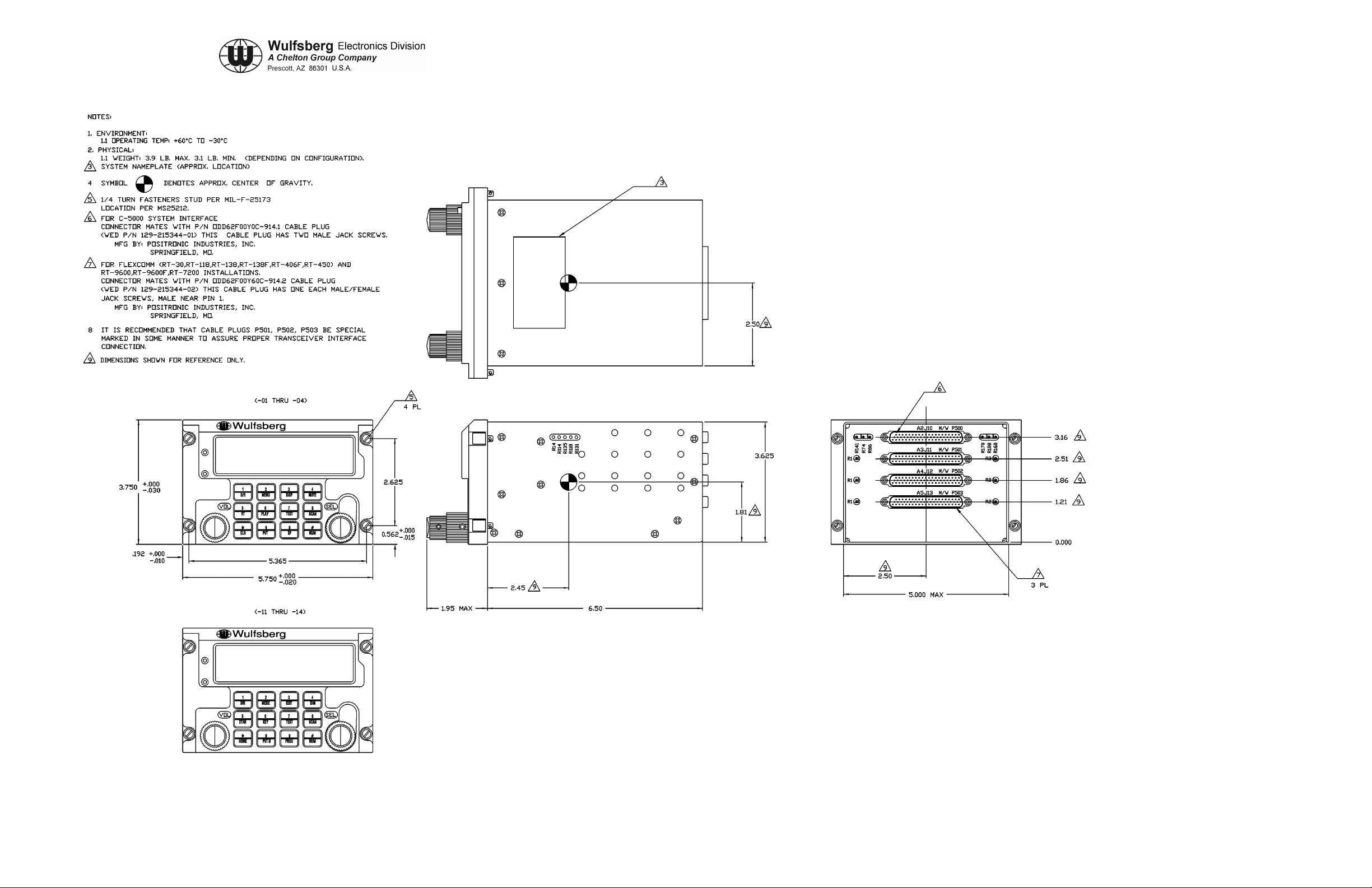
Figure 3-1. C-5000 Envelope Drawing (Sheet 1 of 1)
Dwg No. 154-031300, Rev. F
Publication No. 150-041118 Page 3-7/8
Rev. A Section 3 – Mechanical Installation
Sep 2001
C-5000 COMMUNICATION MANAGEMENT CONTROLLER
INSTALLATION MANUAL
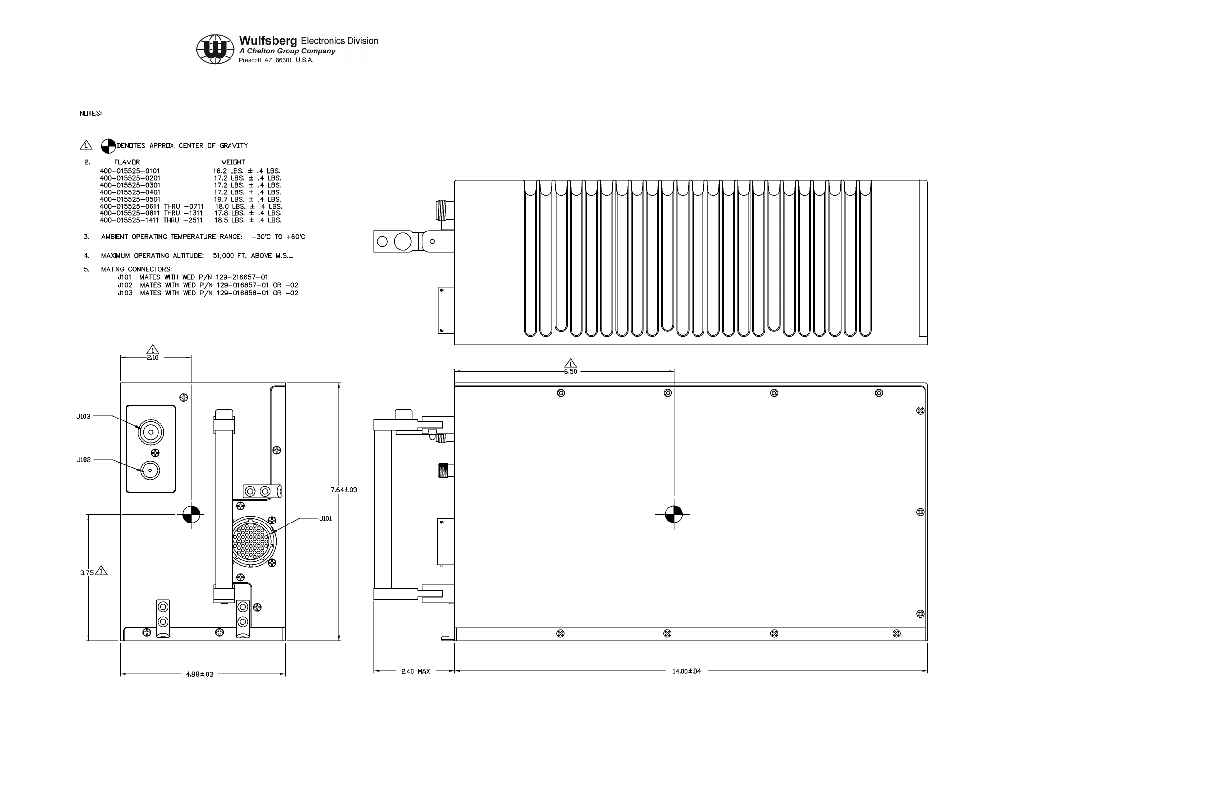
Figure 3-2. RT-5000 Envelope Drawing (Sheet 1 of 1)
Dwg No.154-015525, Rev D
Publication No. 150-041118 Page 3-9/10
Rev. A Section 3 – Mechanical Installation
Sep 2001
C-5000 COMMUNICATION MANAGEMENT CONTROLLER
INSTALLATION MANUAL
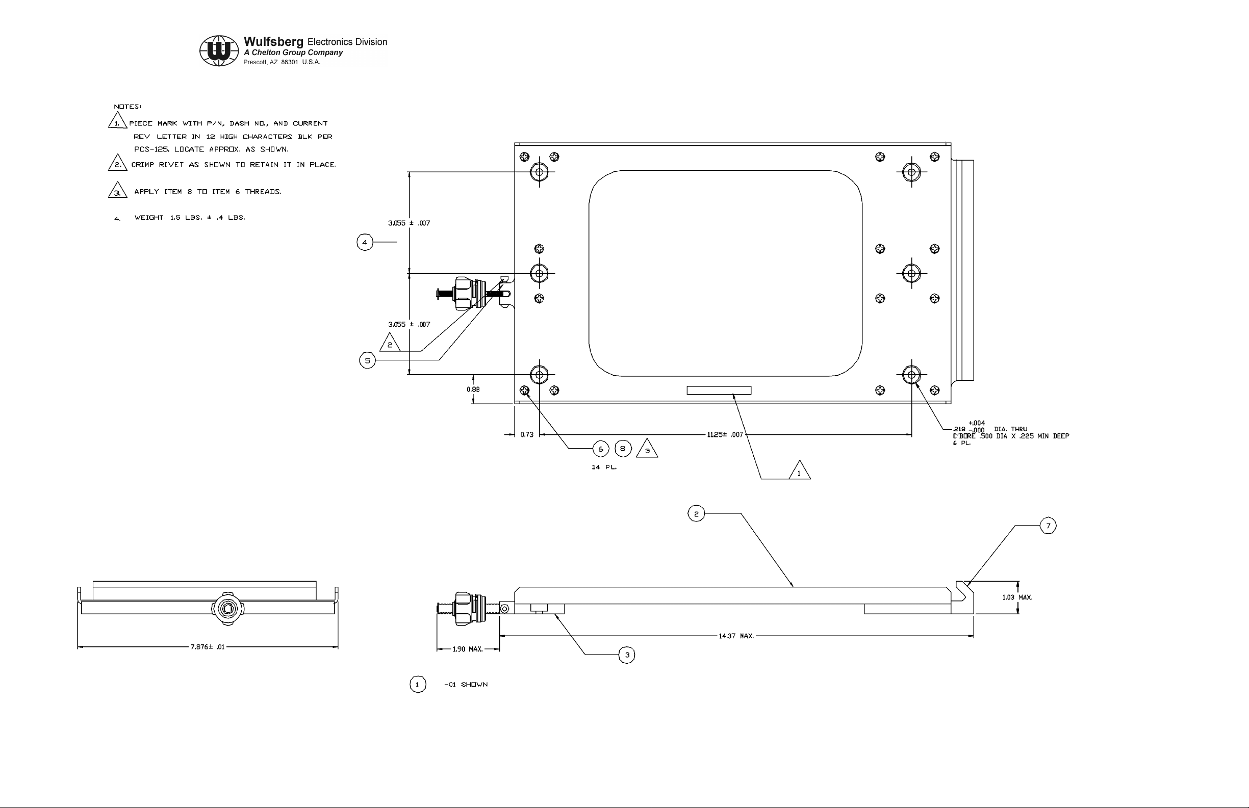
Figure 3-3. RT-5000 Tray Horizontal Mount (Sheet 1 of 1)
Dwg No. 300-316835, Rev D
Publication No. 150-041118 Page 3-11/12
Rev. A Section 3 – Mechanical Installation
Sep 2001
C-5000 COMMUNICATION MANAGEMENT CONTROLLER
INSTALLATION MANUAL
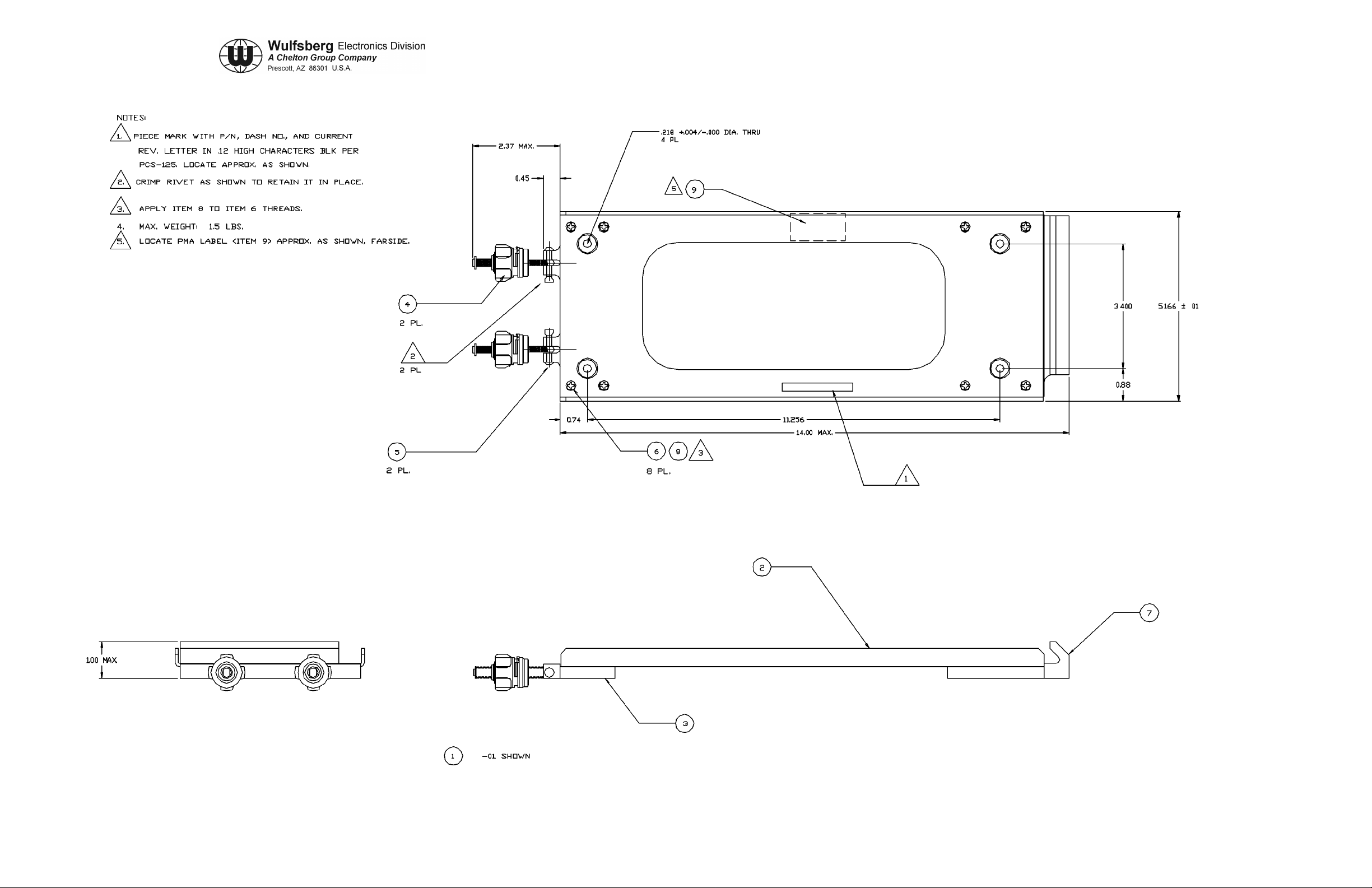
Figure 3-4. RT-5000 Tray Vertical Mount (Sheet 1 of 1)
Dwg No. 300-316605, Rev F
Publication No. 150-041118 Page 3-13/14
Rev. A Section 3 – Mechanical Installation
Sep 2001
C-5000 COMMUNICATION MANAGEMENT CONTROLLER
INSTALLATION MANUAL
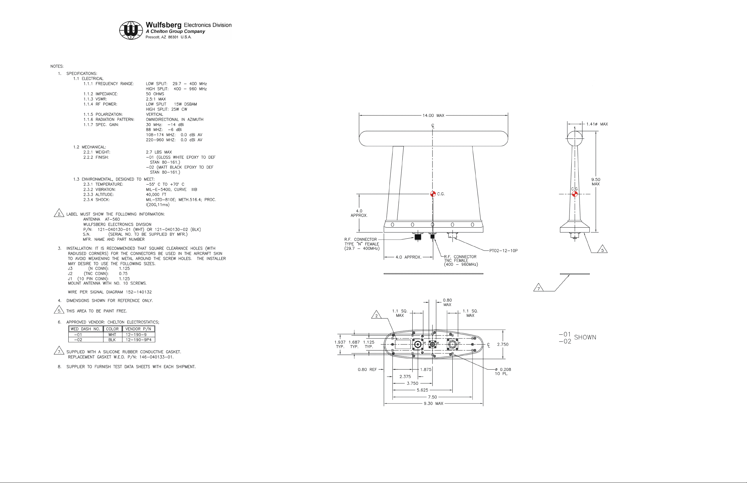
Figure 3-5. AT-560 Envelope Drawing (Sheet 1 of 1)
Dwg No. 121-040130, Rev C
Publication No. 150-041118 Page 3-15/16
Rev. A Section 3 – Mechanical Installation
Sep 2001
C-5000 COMMUNICATION MANAGEMENT CONTROLLER
INSTALLATION MANUAL
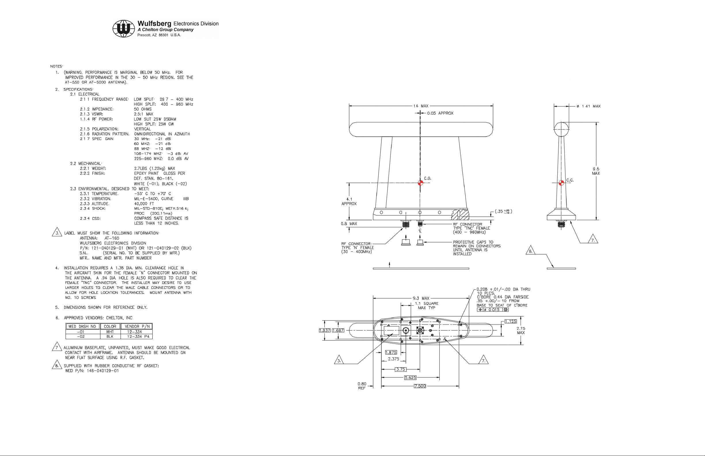
Figure 3-6. AT-160 Envelope Drawing (Sheet 1 of 1)
Dwg No. 121-040129, Rev C
Publication No. 150-041118 Page 3-17/18
Rev. A Section 3 – Mechanical Installation
Sep 2001
C-5000 COMMUNICATION MANAGEMENT CONTROLLER
INSTALLATION MANUAL
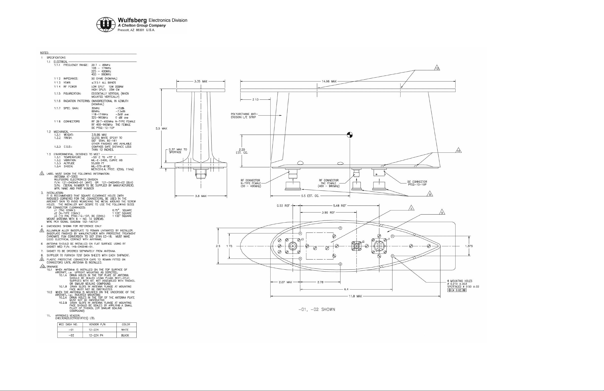
Figure 3-7. AT-5000 Envelope Drawing (Sheet 1 of 1)
Dwg No. 121-040045, Rev A
Publication No. 150-041118 Page 3-19/20
Rev. A Section 3 – Mechanical Installation
Sep 2001
C-5000 COMMUNICATION MANAGEMENT CONTROLLER
INSTALLATION MANUAL
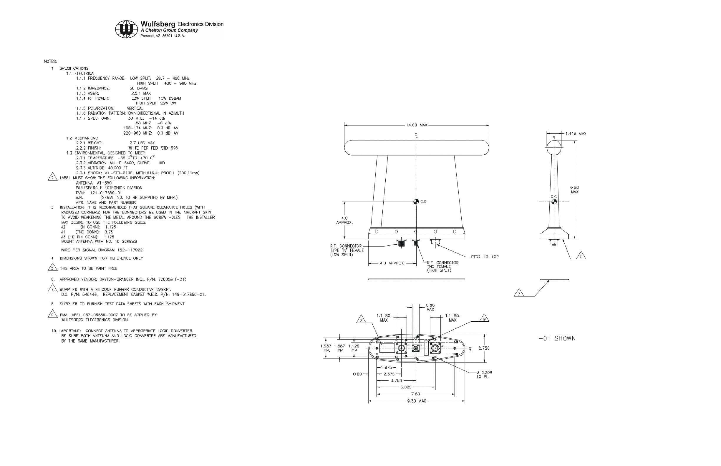
Figure 3-8. AT-550 Envelope Drawing (Sheet 1 of 1)
Dwg No. 121-017850, Rev E
Publication No. 150-041118 Page 3-21/22
Rev. A Section 3 – Mechanical Installation
Sep 2001

C-5000 COMMUNICATION MANAGEMENT CONTROLLER
INSTALLATION MANUAL
Figure 3-9. AT-150 Envelope Drawing (Sheet 1 of 1)
Dwg No. 153-017822, Rev D
Publication No. 150-041118 Page 3-23/24
Rev. A Section 3 – Mechanical Installation
Sep 2001

C-5000 COMMUNICATION MANAGEMENT CONTROLLER
INSTALLATION MANUAL
Figure 3-10. AT-50 Envelope Drawing (Sheet 1 of 1)
Dwg No. 121-016587, Rev G
Publication No. 150-041118 Page 3-25/26
Rev. A Section 3 – Mechanical Installation
Sep 2001

C-5000 COMMUNICATION MANAGEMENT CONTROLLER
INSTALLATION MANUAL
Figure 3-11. AT-51 Envelope Drawing (Sheet 1 of 1)
Dwg No. 121-016796, Rev F
Publication No. 150-041118 Page 3-27/28
Rev. A Section 3 – Mechanical Installation
Sep 2001

C-5000 COMMUNICATION MANAGEMENT CONTROLLER
INSTALLATION MANUAL
Figure 3-12. AT-140 Envelope Drawing (Sheet 1 of 1)
Dwg No. 121-016584, Rev F
Publication No. 150-041118 Page 3-29/30
Rev. A Section 3 – Mechanical Installation
Sep 2001

C-5000 COMMUNICATION MANAGEMENT CONTROLLER
INSTALLATION MANUAL
Figure 3-13. AT-400 Envelope Drawing (Sheet 1 of 1)
Dwg No. 121-016821, Rev B
Publication No. 150-041118 Page 3-31/32
Rev. A Section 3 – Mechanical Installation Sep 2001

C-5000 COMMUNICATION MANAGEMENT CONTROLLER
INSTALLATION MANUAL
Figure 3-14. FC-50 Envelope Drawing (Sheet 1 of 1)
Dwg No. 153-016586, Rev E
Publication No. 150-041118 Page 3-33/34
Rev. A Section 3 – Mechanical Installation
Sep 2001

C-5000 COMMUNICATION MANAGEMENT CONTROLLER
INSTALLATION MANUAL
Figure 3-15. FC-5000 Envelope Drawing (Sheet 1 of 1)
Dwg No. 153-040047, Rev A
Publication No. 150-041118 Page 3-35/36
Rev. A Section 3 – Mechanical Installation
Sep 2001

C-5000 COMMUNICATION MANAGEMENT CONTROLLER
INSTALLATION MANUAL
Figure 3-16. FC-550 Envelope Drawing (Sheet 1 of 1)
Dwg No. 153-017851, Rev D
Publication No. 150-041118 Page 3-37/38
Rev. A Section 3 – Mechanical Installation
Sep 2001

C-5000 COMMUNICATION MANAGEMENT CONTROLLER
INSTALLATION MANUAL
Figure 4-9a. Flexcomm II System Interconnect Drawing (Sheet 1 of 4)
Dwg No. 152-140131, Rev. D
For C-5000/RT-5000 System with AT-5000 or AT-560 Antenna System
Publication No. 150-041118 Page 4-27/28
Rev. A Section 4 –Electrical Installation
Sep 2001

C-5000 COMMUNICATION MANAGEMENT CONTROLLER
INSTALLATION MANUAL
Figure 4-9b. Flexcomm II System Interconnect Drawing (Sheet 2 of 4)
Dwg No. 152-140131, Rev. D
For C-5000/RT-5000 System with AT-550 Antenna System
Publication No. 150-041118 Page 4-29/30
Rev. A Section 4 –Electrical Installation
Sep 2001

C-5000 COMMUNICATION MANAGEMENT CONTROLLER
INSTALLATION MANUAL
Figure 4-9c. Flexcomm II System Interconnect Drawing (Sheet 3 of 4)
Dwg No. 152-140131, Rev. D
For C-5000/RT-5000 System with AT-50 or AT-51 Antenna System
Publication No. 150-041118 Page 4-31/32
Rev. A Section 4 –Electrical Installation
Sep 2001

C-5000 COMMUNICATION MANAGEMENT CONTROLLER
INSTALLATION MANUAL
Figure 4-9d. Flexcomm II System Interconnect Drawing (Sheet 4 of 4)
Dwg No. 152-140131, Rev. D
For C-5000/RT-5000 System with AT-160 or AT-150 Antenna System
Publication No. 150-041118 Page 4-33/34
Rev. A Section 4 –Electrical Installation
Sep 2001

C-5000 COMMUNICATION MANAGEMENT CONTROLLER
INSTALLATION MANUAL
Figure 4-3. C-5000D Standard Installation Wiring Diagram (Sheet 1 of 1)
(Dwg No 147-014995, Rev 6)
Publication No. 150-041118 Page 4-11/12
Rev. A Section 4 –Electrical Installation
Sep 2001

C-5000 COMMUNICATION MANAGEMENT CONTROLLER
INSTALLATION MANUAL
Figure 4-12b. FLEXCOMM Transceivers Installation Wiring Diagram (Sheet 2 of 3)
RT-30, RT-118, RT-138, RT-138F, RT-450 and RT-406F
(Dwg No 147-014991, Rev B)
Publication No. 150-041118 Page 4-43/44
Rev. A Section 4 –Electrical Installation
Sep 2001

C-5000 COMMUNICATION MANAGEMENT CONTROLLER
INSTALLATION MANUAL
Figure 4-12c. FLEXCO M M Transceivers Installation Wiring Diagram (Sheet 3 of 3)
RT-30, RT-118, RT-138, RT-138F,RT-450 and RT-406F
(Dwg No 147-014991, Rev B)
Publication No. 150-041118 Page 4-45/46
Rev. A Section 4 –Electrical Installation
Sep 2001

C-5000 COMMUNICATION MANAGEMENT CONTROLLER
INSTALLATION MANUAL
Figure 4-14. Installation Wiring Diagram (Sheet 1 of 1)
RT-9600 / RT-9600F / RT-7200
(Dwg No 147-014992, Rev 4)
Publication No. 150-041118 Page 4-51/52
Rev. A Section 4 –Electrical Installation
Sep 2001
 Loading...