

Page 1

Operator’s Manual
C-5000
COMMUNICATION MANAGEMENT CONTROLLER
Part Number 31300-1X02-1XX0
Manual Number 150-041102
Revision A
September 18, 2001
Page 2

C-5000 Operator’s Manual
TABLE OF CONTENTS
INTRODUCTION .......................................................................................................................................................4
EATURES
F
RANSCEIVER OVERVIEW
T
TEPS TO SUCCESSFUL SETUP AND OPERATION
S
...................................................................................................................................................................4
..........................................................................................................................................4
.........................................................................................................5
BASIC OPERATION..................................................................................................................................................6
RONT PANEL
F
HE HOME PAGE
T
ETTING THE DISPLAY BRIGHTNESS
S
ETTING THE VOLUME LEVEL
S
ELECTING A PRESET CHANNEL USING THE CURSOR/VALUE KNOB
S
ELECTING A CHANNEL USING THE KEYPAD
S
ELECTING A CHANNEL BY ALPHANUMERIC IDENTIFIER
S
ELECTING THE MANUAL CHANNEL
S
SING THE DIRECT/REPEAT FEATURE
U
ECEIVING/TRANSMITTING
R
NABLING/DISABLING TRANSCEIVERS
E
ONTROLS
& C
.......................................................................................................................................6
........................................................................................................................................................8
...........................................................................................................................9
....................................................................................................................................9
........................................................................10
...........................................................................................................10
.........................................................................................11
........................................................................................................................11
......................................................................................................................11
......................................................................................................................................12
.....................................................................................................................13
Disabling (Turning Off) a Transceiver................................................................................................................13
Enabling (Turning On) a Transceiver.................................................................................................................13
USING THE EDIT PAGE ........................................................................................................................................14
E
DITING A PRESET CHANNEL
DITING A MANUAL CHANNEL
E
HANGING
C
PL & DPL (CTCSS
...................................................................................................................................14
.................................................................................................................................15
AND
DCS) T
ONES
..................................................................................................15
Turning Tones Off................................................................................................................................................15
Selecting a CTCSS Tone......................................................................................................................................16
Selecting a DCS Tone..........................................................................................................................................16
C
HANGING TRANSMIT POWER
HANGING MODULATION TYPE
C
HANGING RECEIVER BANDWIDTH
C
..................................................................................................................................17
...............................................................................................................................17
..........................................................................................................................18
ENHANCED SYSTEM FEATURES.......................................................................................................................19
HONE PATCH MODE
P
IMULCAST OPERATION
S
ELAY OPERATION
R
ELAY/SIMULCAST OPERATION
R
EPEATER OPERATION
R
...............................................................................................................................................19
...........................................................................................................................................19
...................................................................................................................................................20
...............................................................................................................................21
.............................................................................................................................................22
ENCRYPTION FEATURES ....................................................................................................................................23
URNING ENCRYPTION ON AND OFF
T
ELECTING AN ENCRYPTION KEY
S
ERFOR M IN G AN
P
RASING ENCRYPTION KEYS
E
ANUALLY LOADING ENCRYPTION KEYS
M
OTAR...........................................................................................................................................24
....................................................................................................................................25
........................................................................................................................23
.............................................................................................................................23
...............................................................................................................26
PROGRAMMING PRESET CHANNELS .............................................................................................................27
ROGRAMMING PRESET CHANNELS USING THE FRONT PANEL
P
................................................................................27
CONFIGURING THE C-5000 .................................................................................................................................32
ONFIGURING THE
C
ONFIGURING THE
C
ONFIGURING THE
C
C-5000.......................................................................................................................................32
C-5000
C-5000
TO CONTROL AN
TO CONTROL
A N
RT-5000.............................................................................................34
ON
RT-5000......................................................................................35
150-041102 REV. A Page 2 of 61
Page 3

C-5000 Operator’s Manual
ETTING PASSWORDS
S
ETTING MISCELLANEOUS CONFIGURATION OPTIONS
S
ONFIGURING THE
C
...............................................................................................................................................38
.............................................................................................39
C-5000 U
SING A
PC...................................................................................................................40
Downloading a Configuration from RP into the C-5000.....................................................................................40
Uploading a Configuration from the C-5000 into RP.........................................................................................41
RSS SOFTWARE DESCRIPTION AND PROGRAMMING...............................................................................42
EFORE YOU BEGIN
B
AIN MENU OPERATIONS
M
ERSONALITY PROGRAMMING (CONVENTIONAL ANALOG
P
ERSONALITY PROGRAMMING (CONVENTIONAL
P
.................................................................................................................................................42
........................................................................................................................................42
ERSONALITIES
ERSONALITIES
P25 P
FM P
)....................................................................50
)......................................................48
GLOSSARY ...............................................................................................................................................................56
APPENDIX A – CTCSS (PL) TONE CODES ........................................................................................................59
APPENDIX B – MODE 2 OPERATION.................................................................................................................60
150-041102 REV. A Page 3 of 61
Page 4

C-5000 Operator’s Manual
Introduction
The Wulfsberg C-5000 Communication Management Controller (CMC) is a microprocessor-based control head
device that controls one or two Wulfsberg transceivers. The C-5000 supports the full line of Wulfsberg
FLITECOMM, FLEXCOMM I, and FLEXCOMM II transceivers. This manual is intended to quickly instruct the
user on the basic operations of the C-5000 and also outline the advanced operations that set the C-5000 apart from
any other communication device.
Features
The C-5000 provides a host of powerful features, including
• Controls Wulfsberg RT-5000, RT-406F, RT-450, RT-138(F), RT-30, RT-9600(F) and RT-7200 transceivers.
• 350 preset channels, programmable from the front panel or using Wulfsberg’s Remote Programmer software.
• Users can dial in frequencies, PL tones, and transmit power on two “manual” channels.
• Advanced multi-radio modes, such as Simulcast, Relay, Repeater, and Relay-Simulcast.
• Control encryption functions embedded in the RT-5000 transceiver such as P25 Digital Modulation and
encryption with Over the Air Rekey (OTAR) capability.
Transceiver Overview
The C-5000 provides support for the Wulfsberg FLITECOMM, FLEXCOMM I, and FLEXCOMM II transceivers.
It is very important that users know how many radios and what type are connected to the C-5000 since transceivers
have very different capabilities and features. Here is a summary of the supported transceivers and their capabilities.
FLEXCOMM II
This product line consists of the RT-5000 AM/FM transceivers covering the 29.7 to 960 MHz frequency range. The
optional Guard Receiver can be specified as a single channel crystal guard (available in three frequency ranges), a
29.7 – 960 MHz receiver capable of being programmed with two Guard channels, or a receiver with one or two
modules capable of RT-5000’s are equipped with CTCSS and DCS tones on both the Main and Guard Receivers.
The MTM Guard variant of the RT-5000 adds support for P25 and Trunking channels, with encryption and over-theair-rekey (OTAR) capability.
FLEXCOM I
This product line currently consists of the RT-30, RT-138F, and RT-406F transceivers. The C-5000 also supports
the RT-118, RT-138, and RT-450 transceivers, which are no longer manufactured but remain in wide use. The RT30, RT-138F, and RT-406F FM transceivers cover the 29.7 to 49.99 MHz, 138.0 to 173.9975 MHz, and 406.0 to
511.9975 MHz frequency ranges, respectively. These transceivers can be specified with a single-channel, crystalcontrolled, Guard Receiver that operates on a customer-specified frequency. An optional Guard Receiver CTCSS
decoder with programmable Guard Receiver tone can also be specified.
FLITECOMM
This product line is no longer manufactured, but remains in wide use. It consisted of the RT-7200, RT-9600, and
RT-9600F transceivers. They were available with a two-channel, crystal-controlled, Guard Receiver that could be
user-specified for any Guard frequency between 138.000 and 173.9950 MHz (RT-7200) or between 150.000 and
173.9975 MHz (RT-9600/9600F). They were equipped with CTCSS tones on both the Main and Guard Receivers.
150-041102 REV. A Page 4 of 61
Page 5

C-5000 Operator’s Manual
Steps to Successful Setup and Operation
While we would like to pull products out of the box and immediately start to use them, this system is one that takes
a little work to get to that point. The following checklist will help installers and initial users setup the C-5000 and
RT-5000.
1. Connect C-5000 to the transceivers. Note part numbers of the Control head and all transceivers.
C-5000 Part Number = 31300-1X02- ____________
Radio #1 Model # = ___________________ Part Number = ______________________
Radio #2 Model # = ___________________ Part Number = ______________________
2. Configure the C-5000 using the steps outlined in the manual. You must know the last four digits of the C-5000
part number and the last four digits of any RT-5000’s or the model type of any Flexcomm/Flitecomm
Transceiver.
3. If Radio #1 is an RT-5000 that has a MTM Guard Receiver (-06XX or greater) connect a PC to the 9-pin
programming port of the RT-5000 and run the Motorola RSS software.
4. Put the C-5000 in RSS mode for radio #1 and select the first ITM to appear.
5. Using the RSS software, read the codeplug out of the ITM.
6. Modify system settings for your application. Program personalities. Assign zone/Channels. These steps
require significant knowledge of the Motorola software. We encourage enlisting the help of someone familiar
with Motorola RSS software to successfully program the ITM.
NOTE: ZONE 1 CHANNEL 1 MUST BE ASSIGNED TO A PERSONALITY THAT HAS DIFFERENT
RECEIVE AND TRANSMIT FREQUENCIES!!!!!
7. Save the modified codeplug to disk and load it into the ITM.
8. Make a listing of all ZONE/CHANNELS Information needed by the C-5000 preset channel programming.
Zone ______ Channel ______
RX Frequency = ______________________ RX Tone = __________
TX Frequency = ______________________ TX Tone = __________
Modulation = ______________(FM,P25,TRK)
9. Do the above for the second ITM if there is one in Radio #1
10. Do the above for Radio #2 only if its an RT-5000 with an MTM Guard (-06XX or greater)
11. Using the front panel or better yet the Wulfsberg RP software, program all preset channels including the ones
programmed into each ITM module in the steps above.
12. Using a communication analyzer or over the air test, verify that each radio and channel operates properly.
150-041102 REV. A Page 5 of 61
Page 6
Basic Operation
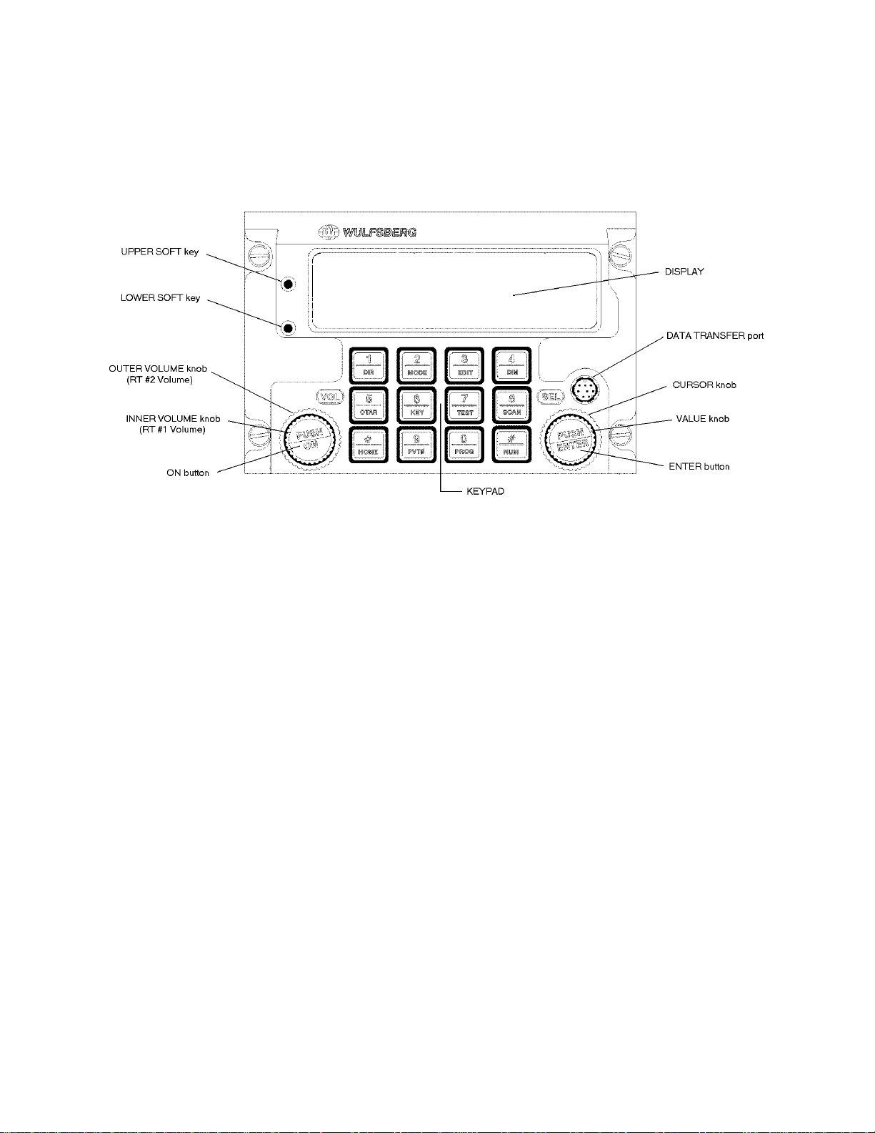
Front Panel & Controls
C-5000 Operator’s Manual
DISPLAY - The C-5000 has a 2 line display, with 20 characters on each line. It provides the visual feedback for the
system. Exactly what is displayed depends on the current operating mode of the C-5000. During normal operation,
the top line shows information for transceiver #1 and the bottom line shows information for transceiver #2.
UPPER SOFT key – This key’s use depends on the current operating mode of the C-5000. Some examples of its
use are: increasing the display brightness, and selecting radio 1’s guard receiver.
LOWER SOFT key - This key’s use depends on the current operating mode of the C-5000. Some examples of its
use are: decreasing the display brightness, and selecting radio 2’s guard receiver.
OUTER VOLUME knob – This rotary switch is used to control the volume of radio 2.
INNER VOLUME knob – This rotary switch is used to control the volume of radio 1.
ON button – This button is used to turn the C-5000 on or off.
CURSOR knob – This rotary switch is used to move the cursor around the displa y.
VALUE knob – This rotary switch is used to modify values above the cursor.
ENTER button – This button’s use is dependent on the C-5000’s current operating mode, but is primarily used to
finalize data entry operations.
DATA TRANSFER PORT – This serial port is used to transfer data between the C-5000 and the Wulfsberg Remote
Programmer software. While preset channels can be programmed from the front panel, the best method is to
use a PC and the Wulfsberg Remote Programming(RP) software.
150-041102 REV. A Page 6 of 61
Page 7

C-5000 Operator’s Manual
KEYPAD – The C-5000 has a 12 button keypad. Each button’s primary functions are described below.
1:DIR Toggles the transceiver under cursor control in and out of DIRECT mode. Use this button
to enter a “1” during keypad entry mode.
2:MODE This button will cycle through the enhanced modes of operation. Use this button to
enter a “2” during keypad entry mode.
3:EDIT This button will display the EDIT PAGE for the transceiver under cursor control. Use
this button to enter “3” during keypad entry mode.
4:DIM This button will display the page used to control the display’s brig htness. Use this button
to enter a “4” during keypad entry mode.
5:OTAR This button will initiate an “Over The Air Rekey” for the transceiver under cursor
control . Use this button to enter a “5” during keypad entry mode.
6:KEY This button will prompt the user for a transmit encryption key to override the preset value
for the transceiver under cursor control. Use this button to enter a “6” during keypad entry mode.
7:TEST This button will override the squelch system of the radio under cursor control, allowing
the user to set the volume level. Use this button to enter a “7” during keypad entry mode
8:SCAN FUNCTION NOT AVAILABLE AT THIS TIME. Use this button to enter a “8”
during keypad entry mode.
*:HOME This button will display the HOME PAGE, except in some advanced modes of
operation, where it will return the user to a previous page or mode of operation. Use this button to
enter a “*” during keypad entry mode.
9:PVTφφφφ This button will toggle the transceiver under cursor control in and out of private mode.
Use this button to enter a “9” during keypad entry mode.
0:PROG This button will display the programming password page. Use this button to enter a “0”
during keypad entry mode.
#:NUM This button will select keypad entry mode, such as for entering a channel number or
frequency using the keypad. Use this button to enter a “#” during keypad entry mode.
150-041102 REV. A Page 7 of 61
Page 8
C-5000 Operator’s Manual
φφφφ
The Home Page
The HOME PAGE is the primary operational page of the C-5000. The HOME PAGE becomes visible when the C5000 is ready for user input, immediately after the power up and initialization sequences have completed. The C5000 can control two radios. When viewing the HOME PAGE, Radio 1 is always displayed on the top line. Radio
2 is always displayed on the bottom line. Virtually all keypad-initiated operations are performed on the radio under
cursor control. The radio under cursor control in the radio whose line the cursor is currently located on. The cursor
can be quickly toggled between radios (display lines) by pressing the ENTER button.
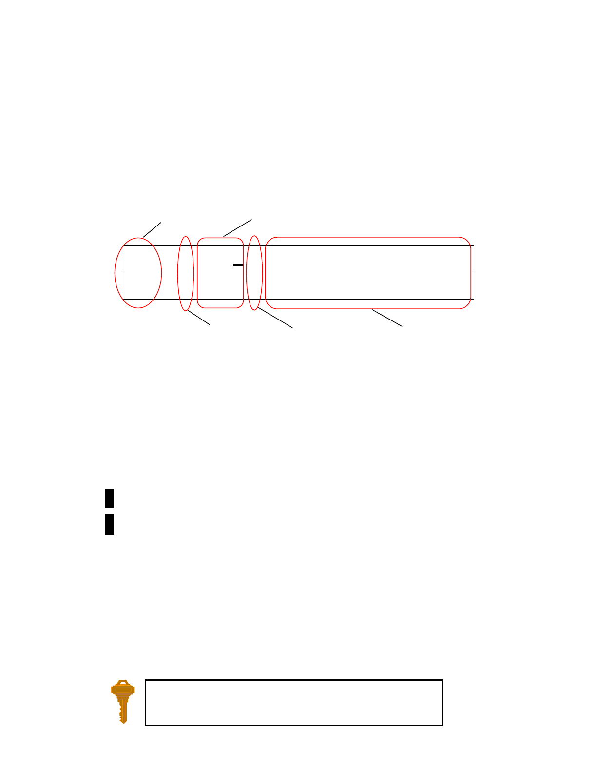
The following illustration is an example of what the HOME PAGE looks like.
Main/Guard
Status Field
1 123
2
Main/Guard Status Fields – These fields display symbols indicating the current status of all the available
transceivers in the system. The symbols are as follows.
.
– Indicates a radio is available, but not enabled.
►
– Indicates a radio is transmitting.
1
– Indicates radio 1 is available and enabled.
2
– Indicates radio 2 is available and enabled.
..1 TACTICAL-001
Encryption
Status Field
Channel Selection Field
→→→→
LUKEAFB TWR1
Direct Mode
Status Field
Alphanumeric
Identifier Field
1
– Indicates radio 1 is receiving.
2
– Indicates radio 2 is receiving.
Encryption Status Field – This field displays the encryption indicator symbol (
a blank if encryption is turned off.
Channel Selection Field – This field displays the currently selected channel.
Direct Mode Status Field – This field displays the direct mode indicator symbol (→→→→) when the current channel is a
direct channel, or the channel has been forced to be a direct channel by pressing the DIR button.
Alphanumeric Identifier Field – This field displays the 12 character name of the currently selected channel, unless
the manual channel is selected, in which case the manual channel’s receive frequency will be displayed.
You can always get back to the HOME PAGE by pressing the HOME
button one or more times.
150-041102 REV. A Page 8 of 61
φφφφ
) when encryption is turned on, or
Page 9

C-5000 Operator’s Manual
←←←←
←←←←
Turning the System On and Off
To power the C-5000 ON, press and hold the ON button for approximately one second. Several version number and
copyright pages appear on the display while the unit performs a selFtest and initializes the attached radio systems.
When initialization is complete, the HOME PAGE will appear on the display.
To power the C-5000 OFF, press and hold the ON button for several seconds. The following message flashes on the
display several times:
!!!USE CAUTION !!!
TURNING SYSTEM OFF
Continue to hold the ON button until the message stops flashing and the display turns off.
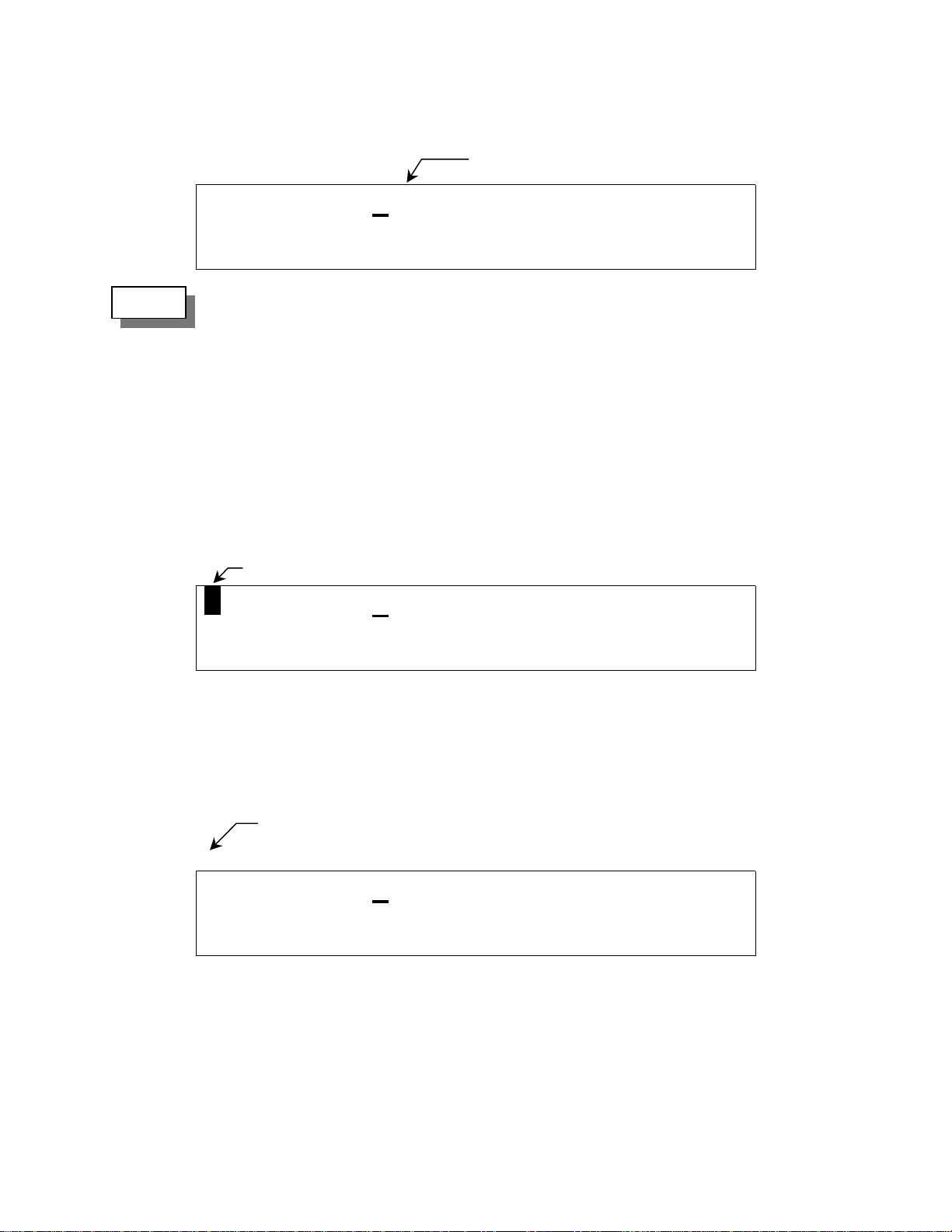
Setting the Display Brightness
When you first power ON the C-5000, the display is at its maximum brightness. To adjust the brightness level,
ensure you are on the HOME PAGE, then press the DIM button. The display will appear as follows.
UP CHANGE DISPLAY
DOWN BRIGHTNESS
Press the UPPER SOFT KEY to brighten the di splay. Press he LOWER SOFT KEY to d im the display. Press the
HOME button to return to the HOME PAGE.
Setting the Volume Level
When you first power ON the C-5000, the volume level will be reset to the level that was active when the unit was
powered down. You can c hange the volume level as follows.
Radio 1
• Place the cursor on the top line of the display.
• Tune to a channel with activity on it or press the TEST button. T his will unsquelch the radio, allowing you to
hear the current volume level.
• Rotate the INNER VOLUME knob clockwise to increase the volume level, or counterclockwise to decrease the
volume level.
Radio 2
• Place the cursor on the bottom line of the display.
• Tune to a channel with activity on it or press the TEST button. T his will unsquelch the radio, allowing you to
hear the current volume level.
150-041102 REV. A Page 9 of 61
Page 10

C-5000 Operator’s Manual
• Rotate the OUTER VOLUME knob clockwise to increase the volume level, or counterclockwise to decrease the
volume level.
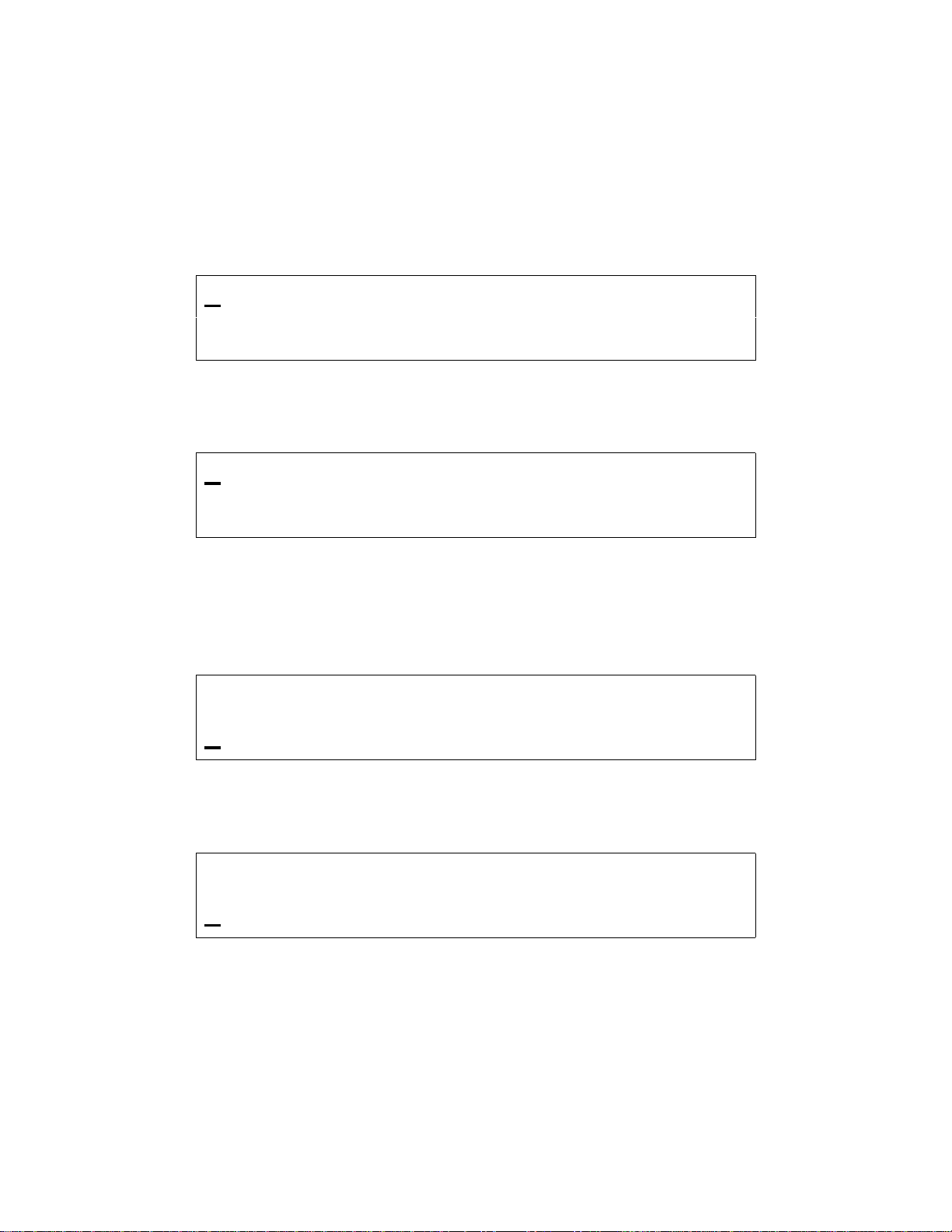
Selecting a Preset Channel Using the Cursor/Value Knob
When the C-5000 first powers on, the selected channels will be reset to those that were active when the unit was
powered down. To select a different preset channel, do one of the following:
• Move the cursor under the least significant digit of the channel number you want to change. The illustration
below shows a user preparing to change the channel for radio 1.
1 123
2
• Turn the VALUE knob clockwise to select the next available channel with a higher number. Turn the VALUE
knob counterclockwise to select the next available channel with a lower number. Keep turning the VALUE
knob until the desired channel is selected.
You can also increment the channel number by 10’s and 100’s. You do this by placing the cursor under the 10’s or
100’s digit and turning the VALUE knob as described above. The following illustration depicts the cursor under the
10’s digit. The 100’s digit would be one to the left of the 10’s digit.
..1 TACTICAL-001
φφφφ
1123
2
Selecting a Channel Using the Keypad
Occasionally, it is desirable to select a preset channel by entering its number via the keypad, rather than dialing it in
with the cursor/value knobs. This can be performed as follows.
..1 TACTICAL-001
φφφφ
→→→→
LUKEAFB TWR1
→→→→
LUKEAFB TWR1
• Place the cursor under any digit of the channel number you want to change.
• Press the NUM button. The following illustration depicts the display after the NUM button has been pressed
while radio 1 was under cursor control.
1 CHAN=..0 <ENTER>
2
• Input the channel number using the keypad buttons.
150-041102 REV. A Page 10 of 61
..1 TACTICAL-001
φφφφ
Page 11

C-5000 Operator’s Manual
φφφφ
• Press the ENTER button.
The input channel number will be selected, assuming it was a valid channel. If you input an invalid cha nnel number,
the display will reappear as depicted above, giving you the opportunity to input a valid channel number. You can
press the HOME button to cancel the input operation and return to the HOME PAGE.
Selecting a Channel by Alphanumeric Identifier
It is sometimes desirable to select a preset channel by name as opposed to number. This can be performed as
follows.
• Place the cursor under the alphanumeric identifier field of the radio you want to tune the channel on. The
following illustrating shows the cursor under radio 1’s alphanumeric identifier field.
1 123
2
• Rotate the VALUE knob clockwise to select the next channel in alphabetic order. Turning the VALUE knob
counterclockwise will select the previous channel in alphabetic order. Continue to turn the VALUE knob until
the desired channel is displayed.
1) The manual channel cannot be selected this way.
NOTE:
2) The cursor will not move under the alphanumeric identifier field if the manual channel is
selected.
Selecting the Manual Channel
The manual channel is used to tune channels not already programmed as presets into the C-5000’s memory. Each
radio has its own manual channel. The manual channel is located at channel number 0, and is displayed as “..M”.
You can select the manual channel by either entering channel 0 from the keypad, or by dialing it in using the
cursor/value knobs. The following illustration depicts a C-5000 with the manual channel for radio 1 selected.
..1 TACTICAL-001
→→→→
L UKEAFB TWR1
1 ..M 156.200
2
The manual channel’s frequency is displayed in place of the alphanumeric identifier for preset channels. Once the
manual channel is selected, press the EDIT button to edit the channel information. The C-5000 automatically stores
the manual channel information on power down.
Using the Direct/Repeat Feature
The C-5000 supports both direct and repeat modes of operation. Any preset channel that has identical transmit and
receive frequencies is considered a direct channel. If the transmit and receive frequencies are different, the C-5000
considers the channel a repeater channel. Repeater channels can be temporarily changed into direct channels by
150-041102 REV. A Page 11 of 61
..1 TACTICAL-001
φφφφ
Page 12
C-5000 Operator’s Manual
φφφφ
φφφφ
pressing the DIR button. This will temporarily copy the receive frequency into the transmit frequency. The direct
mode indicator will light. The following illustration shows radio 1 in direct mode.
Direct Mode Indicator
1 123
2
NOTE:
Receiving/Transmitting
Receiving
The C-5000 is constantly monitoring its radios for reception. When a signal is received, the C-5000 will light the
receive indicator for the receiving radio, and route the audio to the operator’s headset (Assuming the associated
intercom switch is selected). The following illustration depicts Radio #1 receiving.
Pressing the DIR button on a direct channel has no effect.
RX Indicator
..1 TACTICAL-001
1 123
2
..1 TACTICAL-001
→→→→
LUKEAFB TWR1
→→→→
LUKEAFB TWR1
Transmitting
To transmit on a radio system, select the appropriate source on your audio panel, and key the microphone.
Transmission will begin on the radio’s currently selected channel. During the transmission, the radio’s transmit
indicator will light, and the channel’s transmit frequency will be d isplayed. The following illustration depicts radio
1 transmitting.
TX Indicator
►►►►
2
123
..1 TACTICAL-001
φφφφ
→→→→
300.000T
150-041102 REV. A Page 12 of 61
Page 13
C-5000 Operator’s Manual
φφφφ
Enabling/Disabling Transceivers
Disabling (Turning Off) a Transceiver
• Place the cursor under the R/T status indicator. The following illustration shows the cursor under Radio #1’s
status indicator.
1 123
2
• Rotate the VALUE knob once in either direction. The display will indicate the radio has been turned off, as the
following illustrates.
..1 TACTICAL-001
→→→→
LUKEAFB TWR1
. RADIO OFF
2
Enabling (Turning On) a Transceiver
• Place the cursor under the radio’s status indicator. The following illustration shows the cursor under Radio
#2’s status indicator.
1 123
..1 TACTICAL-001
φφφφ
→→→→
LUKEAFB TWR1
. RADIO OFF
• Rotate the VALUE knob once in either direction. The display will indicate the radio has been turned on, as the
following illustrates.
1 123
2
150-041102 REV. A Page 13 of 61
..1 TACTICAL-001
φφφφ
→→→→
LUKEAFB TWR1
Page 14
C-5000 Operator’s Manual
one
Using The Edit Page
The EDIT PAGE allows the operator to temporarily change properties of a preset channel, and permanently change
properties of a manual channel. Precisely which properties can be changed varies with channel and radio type. For
example, transmit power can only be changed on RT-5000 radios, because the other radios do not have variable
power capability. The following illustration is an example of what the EDIT PAGE looks like. Your C-5000’s
display may appear differently depending on the currently selected channel and its associated properties.
Channel
..1
Direct Mode
Indicator
→→→→
506.987R T.17 FM
Receive
Frequency
Receive
T
Modulation
S H 506.987T T.17 ..
Power Level
Bandwidth
Channel Identifier field – This displays the currently selected channel, i.e. the channel you are editing.
Direct Mode Status Field – This field displays the direct mode indicator symbol (→) when the current channel is a
direct channel, or the channel has been forced to be a direct channel by way of the DIR button.
Receive Frequency Field – This field displays the current channel’s receive frequency.
Receive Tone Field – This field displays the current channel’s receive tone.
Modulation Type Field – This field displays the current channel’s modulation type. The modulation types are
displayed as AM, FM, P (P25), and TK (trunking).
Transmit
Frequency
Transmit
Encryption
Key
Channel Bandwidth Field – This field displays the current channel’s bandwidth. Bandwidths are displayed as S
(standard), W (wide), X (extra wide), and N (narrow).
Transmit Power Level Field – This field displays the current channel’s transmit power level. Power level is
displayed as HI for high power or LO for low power.
Transmit Frequency Field – This field displays the current channel’s transmit frequency.
Transmit Tone Field – This field disp lays the current channel’s transmit tone.
Encryption Key Field – This field displays the current channel’s transmit encryption key. The encryption key will
display as a number between 1 and 16, or “..” if no key has been specified for the channel.
Editing a Preset Channel
To temporarily change the properties of a preset channel, do the following.
• On the HOME PAGE, select the preset channel you want to edit.
• Press the EDIT button to load the channel into the EDIT PAGE.
150-041102 REV. A Page 14 of 61
Page 15

C-5000 Operator’s Manual
• Move the cursor under the field containing the channel property you want to edit.
• Use the VALUE knob to change the property to the desired value.
• Press the HOME button to return to the HOME PAGE. The changes will remain in effect until the channel is
changed.
NOTE:
The cursor cannot be moved under channel property fields that are not editable.
Editing a Manual Channel
To change the properties of a manual channel, do the following.
• On the HOME PAGE, select the manual channel you want to edit.
• Press the EDIT button to display the EDIT PAGE.
• Move the cursor under the field containing the channel property you want to edit.
• Use the VALUE knob to change the property to the desired value.
• Press the HOME button to return to the HOME PAGE and save the manual channel’s current state.
NOTE:
The cursor cannot be moved under channel property fields that are not editable.
Changing PL & DPL (CTCSS and DCS) Tones
The C-5000 supports both CTCSS (PL) and DCS (DPL) tones. The tone used by a channel can be temporarily
overridden on the EDIT PAGE. You can select any valid tone, or turn tones off. (Channels programmed to use the
ITM of a Guard receiver module in a RT-5000 cannot be changed)
Turning Tones Off
• Move the cursor under the “T” of the receive tone field, as depicted below.
..1 506.987R T.17 FM
S H 509.987T T.17 ..
• Rotate the VALUE knob clockwise once. The receive tone field will show “…” as depicted belo w.
150-041102 REV. A Page 15 of 61
Page 16
C-5000 Operator’s Manual
..1 506.987R T... FM
S H 509.987T T.17 ..
• Press the ENTER button to move the cursor under the “T” of the transmit tone field.
• Rotate the VALUE knob clockwise once. The transmit tone field will show “…” as depicted below.
..1 506.987R T... FM
S H 509.987T T... ..
Selecting a CTCSS To ne
• Move the cursor under the least significant digit of the tone field you want to change. The illustration below
assumes we want to change the receive tone.
..1 506.987R T.17 FM
S H 509.987T T.17 ..
• Rotate the VALUE knob clockwise to increment the tone, or counterclockwise to decrement the tone. Keep
rotating the VALUE knob until the desired tone is displayed.
NOTE:
Selecting a DCS Tone
• Move the cursor under the most significant digit of the tone field you want to change. The illustratio n below
assumes we want to change the receive tone.
Appendix A lists the frequencies associated with the Wulfsberg CTCSS tone numbers.
..1 506.987R T.17 FM
S H 509.987T T.17 ..
• Rotate the VALUE knob clockwise to increment the tone, or counterclockwise to decrement the tone. Continue
rotating the VALUE knob until the most significant digit is that of the desired tone.
150-041102 REV. A Page 16 of 61
Page 17
C-5000 Operator’s Manual
• Move the cursor under the least significant digit of the tone, as illustrated below.
..1 506.987R T023 FM
S H 509.987T T.17 ..
• Rotate the VALUE knob clockwise to increment the tone, or counterclockwise to decrement the tone. Keep
rotating the VALUE knob until the desired tone is displayed.
A “0-7” in the first position means you are selecting a DCS
tone. This is a special kind of tone rarely used.
Changing Transmit Power
The C-5000 supports the selection of high and low transmit power. Normally high power is used, however, if
interference or other transmit issues are experienced, low power may be selected to help remedy the issue. If you
have a radio that supports multiple power levels, such as the RT-5000, you can alter the power setting from the
EDIT PAGE as follows.
• Move the cursor under the transmit power field, as depicted below.
..1 506.987R T.17 FM
SH509.987T T.17 ..
• Rotate the VALUE knob clockwise once. The power indicator will toggle between high and low with each turn
of the VALUE knob.
Changing Modulation Type
The modulation type can be only be changed on the manual channel, and can only toggle between AM and FM. To
change the manual channel’s modulation type, do the following.
• Move the cursor under the modulation field, as depicted below.
..1 506.987R T.17 FM
S H 509.987T T.17 ..
• Rotate the VALUE knob clockwise once. The modulation indicator will toggle betwee n AM and FM. (118-
136 MHz and 225-400 MHz are normally AM frequencies. All other frequencies are usually FM)
150-041102 REV. A Page 17 of 61
Page 18

C-5000 Operator’s Manual
Changing Receiver Bandwidth
The receiver bandwidth can only be changed on the manual channel. To change the manual channel’s receiver
bandwidth, do the following.
• Move the cursor under the bandwidth field, as depicted below.
..1 506.987R T.17 FM
S H 509.987T T.17 ..
• Rotate the VALUE knob in either direction. Each turn of the VALUE knob will select the next bandwidth
option in the list. Turn the VALUE knob until the desired bandwidth symbol is displayed. The available
options are as follows.
N – Narrow – 12.5 kHz
S – Standard - 25 kHz
W – Wide – 35 kHz
X – Extra Wide – 70 kHz
UNLESS SPECIFICALLY INSTRUCTED OTHERWISE, ALWAYS SELECT “S”.
150-041102 REV. A Page 18 of 61
Page 19

C-5000 Operator’s Manual
←←←←
←←←←
←←←←
←←←←
←←←←
←←←←
Enhanced System Features
Phone Patch Mode
The C-5000 can patch into the phone system using both DTMF and pulse dialing. This requires equipment on the
ground, such as a transceiver and an interface box, to connect the base station radio to the telephone lines. This is
NOT a cellular phone.
• From the HOME PAGE, select the radio and channel. Press the MENU button. The following display page
will appear.
DTMF SELECT PHONE
PULSE DIALING MODE
• Press the UPPER SOFT KEY to select DTMF dialing, or the LOWER SOFT KEY to select pulse dialing. In
either case, the next display page will appear, and will look similar to the following. This example sho ws the
dialing operation being performed on radio 1, channel 1.
SEND 1 ..1
HOME #-_
• Input the digits you want to dial using the keypad. Alpha characters can be input by turning the VALUE knob
until the desired character is displayed, then pressing the ENTER button. P ressing the ENTER button while a
blank is displayed inputs a ½ second delay. As soon as you begin input, the display will change slightly. The
following depicts a sample entry.
SEND 1 ..1
CLR #-12345678*90#
• Press the UPPER SOFT KEY to dial the displayed data, or the LOWER SOFT KEY to erase the displayed data.
• Press the HOME button (LOWER SOFT BUTTON !!!!!!) to return to the HOME PAGE.
Simulcast Operation
Simulcast Mode allows you to transmit simultaneously to two other locations that have radios tuned to different
frequencies. At the same time, the Main RT systems and Guard Receivers are able to receive on their currently
selected channels. You can establish simulcast operation as follows.
150-041102 REV. A Page 19 of 61
Page 20

C-5000 Operator’s Manual
• Ensure you are on the HOME PAGE.
• Select the desired channel for radio 1.
• Select the desired channel for radio 2.
• Press the MODE button until the following displa y pa ge appears.
PRESS ENTER BUTTON
FOR SIMULCAST MODE
• Press the ENTER button. The following illustrates the SIMULCAST PAGE for radio 1 on channel 1 and radio
2 on channel 2.
SIMULCAST MODE
1 ..1 2 ..2
• Press the HOME button to exit simulcast mode and return to the HOME PAGE.
• Use either RT1 or RT2 mic position on the audio selector panel and initiate a transmissio n. B oth Radios will
transmit at the same time.
Relay Operation
Relay Mode allows your aircraft’s C-5000-based transceiver system to function as a cross-band repeater. If a Relay
Mode link is established between two locations, a message received from one location is automatically retransmitted
to the other. You can establish relay operation as follows.
• Ensure you are on the HOME PAGE.
• Select the desired channel for radio 1.
• Select the desired channel for radio 2.
• Press the MODE button until the following displa y pa ge appears.
150-041102 REV. A Page 20 of 61
Page 21

C-5000 Operator’s Manual
PRESS ENTER BUTTON
FOR RELAY MODE
• Press the ENTER button. The following illustrates the RELAY PAGE for radio 1 on channel 1 and radio 2 on
channel 2.
RELAY MODE
1 ..1 2 ..2
• Press the HOME button to exit relay mode and return to the HOME PAGE.
Relay/Simulcast Operation
Relay-Simulcast mode combines the functions of Relay Mode and Simulcast Mo de. It allows you to establish an
automatic radio link with two other locations that have radios tuned to different frequencies in different frequency
bands, and allows you to transmit to those same locations simultaneously. You can establish relay/simulcast
operation as follows.
• Ensure you are on the HOME PAGE.
• Select the desired channel for radio 1.
• Select the desired channel for radio 2.
• Press the MODE button until the following displa y pa ge appears.
PRESS ENTER BUTTON
FOR RELAY/SIMULCAST
• Press the ENTER button. The following illustrates the RELAY/SIMULCAST PAGE for radio 1 on channel 1
and radio 2 on channel 2.
RELAY/SIMULCAST MODE
1 ..1 2 ..2
• Press the HOME button to exit relay/simulcast mode and return to the HOME PAGE.
150-041102 REV. A Page 21 of 61
Page 22

C-5000 Operator’s Manual
Repeater Operation
Repeater mode allows the C-5000-based system to act as an airborne repeater, providing a radio link between two
ground locations that transmit and receive in the same frequency band. You can establish repeater operation as
follows.
• Ensure you are on the HOME PAGE.
• Select the desired channel for radio 1.
• Press the MODE button until the following displa y pa ge appears.
PRESS ENTER BUTTON
FOR REPEATER MODE
• Press the ENTER button. The following illustrates the REPEATER PAGE for radio 1 on channel 1 and radio 2
on channel 2.
REPEATER MODE
1 ..1 2 RCV
• Press the HOME button to exit repeater mode and return to the HOME PAGE.
NOTE: Repeater operation on channels that use the Guard module in the transceiver must
cannot accomplished using this method. Any P25 or Encryption capable channels cannot
be setup in repeater mode unless special channels are programmed. The following
procedure should be followed under this condition:
1) Select the repeater channel on RT #1.
2) Press DIR button to put RT #1 into direct mode.
3) Select the repeater channel alternate on RT #2.
4) Enter into repeater mode using the procedure above.
150-041102 REV. A Page 22 of 61
Page 23

C-5000 Operator’s Manual
φφφφ
Encryption Features
Turning Encryption On and Off
Put the cursor on the top or bottom line depending on which radio is to be selected. Press the PV T button to toggle
encryption on and off. If the C-5000 has been configured to control an RT-5000 with an encryption module and the
preset channel being used has been set up for encryption, the privacy indicator will light.
NOTE:
Encryption can only be turned on for channels that have been pre-programmed with an encryption
key. Three error beeps will sound if the channel has not been setup for encryption.
Changing the channel will automatically reset the encryption setting to OFF. The
encryption device in the RT-5000 will still decode encrypted messages i.e. the encryption
ON/OFF affects only the transmit and not the receive function of the encryption unit.
Selecting an Encryption Key
The preset encryption key (sometimes called KEYMAT) for a channel can be temporarily changed as follows.
• Ensure you are on the HOME PAGE, and the cursor is on the line of the radio you wish to select and encryption
capable channel is also selected.
• Press the KEY button. The following illustrates the display when the KEY button was pressed with the cursor
on the top line, i.e. on radio 1. If the KEY button is pressed on a channel that has not been preset to use
encryption, three warning beeps will sound.
TX KEY=PSET<ENTER>
2
..1 TACTICAL-001
• Rotate the VALUE knob to change the encryption key. A value of “PSET” indicates you want to use the
channel’s preset encryption key. A numeric value (1-16) indicates you want to override the preset key with the
specified key.
• Press the ENTER button to accept the displayed key. The display will return to the HOME PAGE.
• When transmitting, a if encryption keys are properly loaded, a tone at the start of the transmission will be
generated by the radio and heard by the operator. Begin speaking AFTER the tone or part of your transmission
will be lost.
• When transmitting in the encrypted mode, if you hear a continuous warble tone, this indicates that the
encryption key(s) have not been loaded. Either ma nually enter e ncryption keys or perform an OTAR if yo ur
system has that capability.
• The newly selected KEYMAT WILL REMAIN even if the channel is changed in effect until power down.
150-041102 REV. A Page 23 of 61
Page 24

C-5000 Operator’s Manual
φφφφ
φφφφ
Performing an OTAR
• Ensure you are on the HOME PAGE, and the cursor is on the line of the radio you wish to select and an OTAR
capable channel is also selected.
• Press the OTAR button. The following illustrates the display when the OTAR button was pressed with radio 1
under cursor control.
1 ENTER=START OTAR
2
• Press the ENTER button to initiate the OTAR process. The status of the OTAR will be displayed on the radio’s
display line. Status messages include “OTAR REQUESTED”, “OTAR IN PROGRESS”, “OTAR
ABORTING”, “OTAR COMPLETE”, and “OTAR FAILED”. The following illustrates the display with an
OTAR in progress.
..1 TACTICAL-001
φφφφ
1 OTAR IN PROGRESS
2
• When the OTAR is finished, the display will indicate its success or failure. The following illustrates the display
after a successful OTAR.
..1 TACTICAL-001
1 OTAR COMPLETE
2
• Press the HOME button to acknowledge the completion of the OTAR and return to normal HOME PAGE
operation.
..1 TACTICAL-001
φφφφ
• Normal OTAR operations take 10 – 30 seconds depending on signal strength and channel availability.
The OTAR process can be aborted by pressing the HOME button while the “OTAR IN PROGRESS” message is
being displayed. Doing so will send the abort command to the digital transceiver, and display a status message like
the following.
1 OTAR ABORTING
2
NOTE:
150-041102 REV. A Page 24 of 61
The OTAR process will automatically time-out after 2 minutes of unsuccessful OTAR attempts.
..1 TACTICAL-001
Page 25
C-5000 Operator’s Manual
←←←←
←←←←
Erasing Encryption Keys
It may be desirable to erase the encryption keys contained in a RT-5000 transceiver. For example, prior to sending
the unit in for service. This can be accomplished as follows.
• Ensure you are on the HOME PAGE, and the cursor is on an encryption capable channel.
• Press the PROG button. You will be prompted to enter a password, as follows.
ENTER PASSWORD 2
#=.... <ENTER>
• Input the appropriate password using the keypad and press the ENTER button.
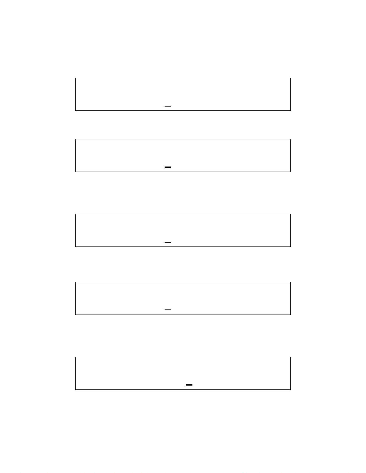
• Press the MODE button until the following displa y pa ge appears.
PROG: 2=NEXT 3=BACK
<ENTER>= KEY ERASE
• Press the ENTER button to invoke the KEY ERASE PAGE, depicted below.
START KEY ERASE
RADIO=1 ITM=VHF138
• Use the cursor/value knobs to select the radio and digital receiver module you want to erase the encryption keys
from. Press the UPPER SOFT KEY to initiate the erase process. The display will appear similar to the
following.
END KEY ERASE
RADIO #1 KEYS ERASED
• Press the UPPER SOFT KEY to acknowledge the key erase is complete. The display will return to the main
KEY ERASE PAGE, allowing you to select another radio and/or digital transceiver module to erase.
• When finished erasing the keys from all desired modules, press the HOME button to return to the HOME
PAGE.
150-041102 REV. A Page 25 of 61
Page 26

C-5000 Operator’s Manual
←←←←
←←←←
Manually Loading Encryption Keys
It may be desirable to manually load the encryption keys contained in a RT-5000 digital transceiver. This can be
accomplished as follows.
• Ensure you are on the HOME PAGE, and the cursor is on an encryption capable channel.
• Press the PROG button. You will be prompted to enter a password, as follows.
ENTER PASSWORD 2
#=.... <ENTER>
• Input the appropriate password using the keypad and press the ENTER button.
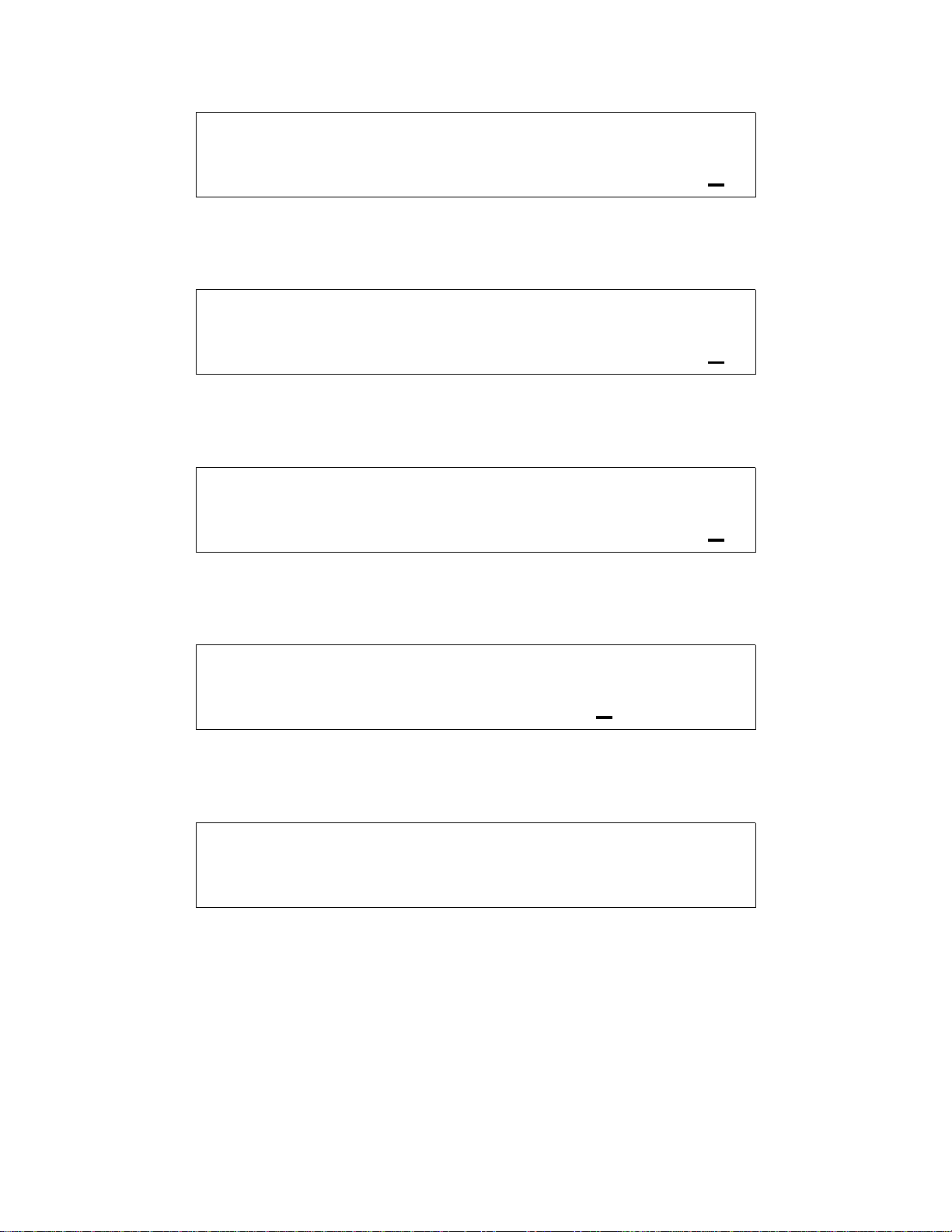
• Press the MODE button until the following displa y pa ge appears.
PROG: 2=NEXT 3=BACK
<ENTER>= KVL LOAD
• Press the ENTER button to invoke the KVL LOAD PAGE, depicted below.
START KVL LOAD
RADIO=1 ITM=VHF138
• Use the cursor/value knobs to select the radio and desired Internal Transceiver Module (ITM) you want to load
the encryption keys . T he RT-5000 can have up to two modules covering two frequency bands per unit. Only
available options will be displayed. Once the desired radio and ITM have been selected, press the UPPER
SOFT KEY to initiate the load process. The display will appear similar to the following.
END KVL LOAD
RADIO #1 IN KVL MODE
• Connect the Key-loader device to the transceiver data port. Load the desired keys using the procedure for the
key-loader as prescribed its manufacturer.
• Press the UPPER SOFT KEY to acknowledge the key load is complete. The display will return to the main
KVL LOAD PAGE, allowing you to select another radio and/or digital transceiver module to load.
• When finished loading the keys to all desired modules, press the HOME button to return to the HOME PAGE.
150-041102 REV. A Page 26 of 61
Page 27

C-5000 Operator’s Manual
Programming Preset Channels
WARNING: CONFIGURING THE C-5000 MUST BE PERFORMED BEFORE PRESET CHANNELS
ARE PROGRAMMED FOR THE UNIT TO OPERATE PROPERLY !!!!
Programming Preset Channels Using the Front Panel
Although Wulfsberg highly recommends using the PC based Remote Programmer software to program preset
channels for the C-5000, they can be programmed from the front panel. The process is as follows.
• Ensure you are on the HOME PAGE.
• Press the PROG button. If the C-5000 has been programmed to require a password to enter this mode, you will
be prompted to enter a password, as follows.
ENTER PASSWORD 2
#=.... <ENTER>
• Input the appropriate password using the keypad and press the ENTER button.
• Press the MODE button until the following displa y pa ge appears.
PROG: 2=NEXT 3=BACK
<ENTER>= CHANNELS
• Press the ENTER button to invoke the CHANNEL MAIN MENU PAGE, d epicted below.
PROG: CHANNEL
2=ADD 3=CHG 4=DEL
• Press the MODE button to add a new channel or the EDIT button to modify an existing channel. The pages are
nearly identical for both functions. The illustrations that follow assume we are adding a channel, i.e. we pressed
the MODE button.
150-041102 REV. A Page 27 of 61
Page 28

C-5000 Operator’s Manual
PROG: 2=NEXT 3=BACK
ADD-..1
• Use the cursor/value knobs to select the number for the new channel. Only available channel numbers will be
displayed. Press the MODE button to go to the next menu page.
PROG: 2=NEXT 3=BACK
R/TSYS#=1
• Use the cursor/value knobs to select the radio this channel is being programmed for. Press the MODE button to
go to the next menu page.
• If both radios are RT-5000’s with the same part number, both radios will be able to use any channel. In this
case, set this value to “1”.
PROG: 2=NEXT 3=BACK
CHAN ID=............
• Use the cursor/value knobs to input the alphanumeric identifier for the channel being programmed. This
identifier can be a maximum of 12 characters in length. Turning the VALUE knob will enumerate all the
characters available for the identifier. Press the MODE button to go to the next menu page.
PROG: 2=NEXT 3=BACK
CHANNEL TYPE= FM
• Use the cursor/value knobs to input the modulation type for the channel being programmed. This can be AM,
FM, P (P25), or TK (trunki ng). Press the MODE button to go to the next menu page.
PROG: 2=NEXT 3=BACK
ZONE= .. CHANNEL= ..
• Use the cursor/value knobs to input the zone and channel number for a RT-5000 digital transceiver channel.
Leave these fields blank if you are not programming a digital transceiver channel. Press the MODE button to
go to the next menu page.
150-041102 REV. A Page 28 of 61
Page 29
C-5000 Operator’s Manual
• IF THE CHANNEL IS TO BE PROGRAMMED FOR THE INTERNAL TRANSCEIVER MODULE IN
THE RT-5000, THE ZONE AND CHANNEL MUST MATCH THE ZONE, CHANNEL, AND
FREQUENCY INFORMATION PROGRAMMED INTO THE ITM.
PROG: 2=NEXT 3=BACK
RX FREQ=000.000
• Use the cursor/value knobs or the keypad to input the channel’s receive frequency. Press the MODE button to
go to the next menu page.
PROG: 2=NEXT 3=BACK
RX TONE=...
• Use the cursor/value knobs to input the channel’s receive tone. Refer to the section on changing tones via the
EDIT PAGE for details on specifying DCS and CTCSS tones. Press the MODE button to go to the next menu
page.
PROG: 2=NEXT 3=BACK
TX FREQ=000.000
• Use the cursor/value knobs or the keypad to input the channel’s transmit frequency. Specifiying a transmit
frequency of 000.000 indicates the channel is a receive-only channel. Press the MODE button to go to the next
menu page.
PROG: 2=NEXT 3=BACK
TX TONE=...
• Use the cursor/value knobs to input the channel’s transmit tone. Refer to the sectio n on changin g tones via the
EDIT PAGE for details on specifying DCS and CTCSS tones. Press the MODE b utton to go to the next menu
page.
PROG: 2=NEXT 3=BACK
TX POWER= HI
• Use the cursor/value knobs to input the channel’s transmit power as HI or LO. Press the MODE button to go to
the next menu page.
150-041102 REV. A Page 29 of 61
Page 30

C-5000 Operator’s Manual
PROG: 2=NEXT 3=BACK
ENCRYPTION TYPE=CLR
• Use the cursor/value knobs to input the channel’s encryption type. T his op tion can be CLR (no encryption),
EXT (external encryption), STD (internal encryption on internal transceiver module), or OTAR (internal
encryption with OTAR capability on internal transceiver module). Press the MODE button to go to the next
menu page.
PROG: 2=NEXT 3=BACK
ENCRYPTION KEY= ..
• Use the cursor/value knobs to input the channel’s encryption key. This page will only appear if applicable, i.e.
an encryption type of STD or OTAR was specified above. Press the MODE button to go to the next menu page.
PROG: 2=NEXT 3=BACK
RX BANDWIDTH= STD
• Use the cursor/value knobs to input the channel’s receive bandwidth. Valid options are STD (standard),
NARROW, W IDE, and X-WI DE (extra wide). Press the MOD E button to go to the next menu page. Normal
setting is STD.
PROG: 2=NEXT 3=BACK
4=ADVANCED FEATURES
• Typically, the previous channel properties are all you need to specify. Pressing the MODE button will skip over
the “advanced features” menu pages to the page that lets you permanently save your channel.
• Channels using an ITM in the RT-5000 will NEVER require the user to input advanced information.
• Press the DIM button to continue with the “advanced features”.
PROG: 2=NEXT 3=BACK
2ND IF INJECTION= HI
• Use the cursor/value knobs to input the channel’s second I.F. Injection as HI or LO. The default is HI. Press
the MODE button to go to t he next menu page.
150-041102 REV. A Page 30 of 61
Page 31
C-5000 Operator’s Manual
PROG: 2=NEXT 3=BACK
3RD IF INJECTION= HI
• Use the cursor/value knobs to input the channel’s third I.F. Injection as HI or LO. The default is LO. Pr ess the
MODE button to go to the next menu page .
PROG: 2=NEXT 3=BACK
RX AUDIO PHASE= 0
• Use the cursor/value knobs to input the channel’s receive audio phase as 0 or 180. The default is 0. Press the
MODE button to go to the next menu page .
PROG: 2=NEXT 3=BACK
TX AUDIO PHASE= 0
• Use the cursor/value knobs to input the channel’s transmit audio phase as 0 or 180. The default is 0. Press the
MODE button to go to the next menu page .
PROG: 2=NEXT 3=BACK
TX DEVIATION= 5.0KHZ
• Use the cursor/value knobs to input the channel’s transmit deviation. This can be 3.0KHz, 5.0KHz, 4.0KHz, or
5.6KHz. The default is 5.0KHz. Press the MODE button to go to the next menu page.
PROG: 2=SAVE 3=BACK
..1 PRESET CHAN1
• Press the MODE button to permanently save the channel and return to the CHANNEL MAIN MENU PAGE.
You may also review your changes by pressing the EDIT button, or cancel the operation by pressing the HOME
button.
150-041102 REV. A Page 31 of 61
Page 32

C-5000 Operator’s Manual
Configuring the C-5000
Configuring the C-5000
Although Wulfsberg highly recommends using the PC based Remote Programmer software to specify the C-5000’s
configuration, it can be specified from the front panel. The process is as follows.
• Ensure you are on the HOME PAGE.
• Press the PROG button. You will be prompted to enter a password, as follows.
ENTER PASSWORD 2
#=.... <ENTER>
• Input the appropriate password using the keypad and press the ENTER button.
• Press the MODE button until the following displa y pa ge appears.
PROG: 2=NEXT 3=BACK
<ENTER>= CFG SYSTEM
• Press the ENTER button. You will be prompted to enter a password, as follows.
ENTER PASSWORD 1
#=.... <ENTER>
• Input the appropriate password and press the ENTER button. The display will appear as follows.
SETUP: 2=NEXT 3=BACK
C5000 P/N = 1220
• Use the cursor/value knobs to input the last four digits of your C-5000’s part number. Press the MODE button
to display the next menu page.
150-041102 REV. A Page 32 of 61
Page 33

C-5000 Operator’s Manual
SETUP: 2=NEXT 3=BACK
ENTER=SETUP RADIO #1
• You can press the ENTER button to configure radio 1. Refer to the sections on configuring RT-5000 and non-
RT-5000 radios for details on these sub-menu pages. Press the MODE button to display the next menu page.
SETUP: 2=NEXT 3=BACK
ENTER=SETUP RADIO #2
• You can press the ENTER button to configure radio 2. Refer to the sections on configuring RT-5000 and non-
RT-5000 radios for details on these sub-menu pages. Press the MODE button to display the next menu page.
SETUP: 2=NEXT 3=BACK
ENTER=CHG PASSWORD 1
• You can press the ENTER button to change the system configuration password. Refer to the section on
changing passwords for details on these sub-menu pages. Press the MODE button to display the next menu
page.
SETUP: 2=NEXT 3=BACK
ENTER=CHG PASSWORD 2
• You can press the ENTER button to change the programming password. Refer to the section on changing
passwords for details on these sub-menu pages. Press the MODE button to display the next menu page.
SETUP: 2=NEXT 3=BACK
ENTER=SETUP MISC.
• You can press the ENTER button to change miscellaneous system properties, such as system encryption, side-
tones, and de-emphasis. Refer to the section on miscellaneous confi guration options for details on these submenu pages. Press the MODE button to display the next menu page.
150-041102 REV. A Page 33 of 61
Page 34

C-5000 Operator’s Manual
SYSTEM SETUP MODE
HOME=EXIT 2=REVIEW
• Press the HOME button to exit system configuration, or the MODE button to review current settings.
Configuring the C-5000 to Control an RT-5000
This section drills down into the radio setup sub-menu pages. Refer to the section on configuring the C-5000 for
details on how to reach these menu pages. This section assumes the C-5000 part number you entered indicated an
RT-5000 was present for Radio #1. We pick up at the following display page.
SETUP: 2=NEXT 3=BACK
ENTER=SETUP RADIO #1
• Press the ENTER button to begin configuring the RT-5000.
SYS #1:2=NEXT 3=BACK
RT-5000 P/N = 0703
• Use the cursor/value knobs to input the last four digits of your RT-5000’s part number. Press the MODE button
to display the next menu page.
SYS #1:2=NEXT 3=BACK
ENTER=SETUP GUARD #1
• This page will only display if RT-5000 part number entered indicates a Guard receiver is present. Pressing the
ENTER butt on invokes the preset chan nel programming menu pages for the Guard channel. Refer to the
section on programming a preset channel for details since programming a Guard channel is very similar to
programming a preset channel.
SYS #1:2=NEXT 3=BACK
RADIO MODE = 1
• This page will only display if RT-5000 part number entered indicates an ITM is present. Use the cursor/value
knobs to select a value of 1 or 2. Mode 1 indicates that the ITM should act as part of the main transceiver, i.e.
the two transceivers appear to be a single unit. Mode 2 indicates that the ITM should not act as part of the
main, i.e. behave as a Guard receiver. . Press the MODE button to display the next menu page.
150-041102 REV. A Page 34 of 61
Page 35

C-5000 Operator’s Manual
←←←←
←←←←
INC 2=NEXT 3=BACK
DEC SQUELCH LVL=160
• This page allows you to set the RT-5000’s squelch level. Press the UPPER SOFT KEY to increase the squelch
level, or the LOWER SOFT KEY to decrease squelch level. T he squelch level determines the signal strength
required by the RT-5000 to open its audio gates, allowing you to hear what it is receiving. The larger the
number, the stronger the required signa l . Press the MODE button to display the next menu page.
SETUP RADIO #1
HOME=EXIT 2=REVIEW
• Press the HOME button to exit the radio setup menu pages, or press the MODE button to review the current
settings.
Configuring the C-5000 to Control A Non RT-5000
This section drills down into the radio setup sub-menu pages. Refer to the section on configuring the C-5000 for
details on how to reach these menu pages. This section assumes the C-5000 part number you entered indicated a
Flitecomm or Flexcomm I radio was present on radio #2. We pick up at the following display page.
SETUP: 2=NEXT 3=BACK
ENTER=SETUP RADIO #2
• Press the ENTER button to begin config uring the radio.
SYS #2:2=NEXT 3=BACK
RT-30 PRESENT-NO
• Use the cursor/value knobs to tell the C-5000 if an RT-30 is present. Press the MODE button to display the
next menu page.
SYS #2:2=NEXT 3=BACK
RT-118 PRESENT-NO
• Use the cursor/value knobs to tell the C-5000 if an RT-118 is present. Press the MODE button to display the
next menu page.
150-041102 REV. A Page 35 of 61
Page 36

C-5000 Operator’s Manual
SYS #2:2=NEXT 3=BACK
RT-138 PRESENT-YES
• Use the cursor/value knobs to tell the C-5000 if an RT-138 is present. Press the MODE button to display the
next menu page.
SYS #2:2=NEXT 3=BACK
RT-138F PRESENT-NO
• Use the cursor/value knobs to tell the C-5000 if an RT-138F is present. Press the MODE button to display the
next menu page.
SYS #2:2=NEXT 3=BACK
RT-450 PRESENT-NO
• Use the cursor/value knobs to tell the C-5000 if an RT-450 is present. Press the MODE button to display the
next menu page.
SYS #2:2=NEXT 3=BACK
RT-406F PRESENT-NO
• Use the cursor/value knobs to tell the C-5000 if an RT-406F is present. Press the MODE button to display the
next menu page.
SYS #2:2=NEXT 3=BACK
RT-9600F PRESENT-NO
• Use the cursor/value knobs to tell the C-5000 if an RT-9600F is present. Press the MODE button to display the
next menu page.
SYS #2:2=NEXT 3=BACK
RT-9600 PRESENT-NO
• Use the cursor/value knobs to tell the C-5000 if an RT-9600 is present. Press the MODE button to display the
next menu page.
150-041102 REV. A Page 36 of 61
Page 37

C-5000 Operator’s Manual
SYS #2:2=NEXT 3=BACK
RT-7200 PRESENT-NO
• Use the cursor/value knobs to tell the C-5000 if an RT-7200 is present. Press the MODE button to display the
next menu page.
SYS #2:2=NEXT 3=BACK
GUARD #1 PRESENT-YES
• Use the cursor/value knobs to tell the C-5000 if a Guard is present. Press the MODE button to display the next
menu page.
SYS #2:2=NEXT 3=BACK
ENTER=SETUP GUARD #1
• This page only appears if a guard is present. Press the ENTER button to configure the first Guard channel.
Refer to the preset channel programming section for details on the menu pages that appear. Press the MODE
button to di splay the next menu page.
SYS #2:2=NEXT 3=BACK
GUARD #2 PRESENT-YES
• This page only appears if a second Guard is possible. Use the cursor/value knobs to tell the C-5000 if a second
Guard is present. Press the MODE button to display the next menu page.
SYS #2:2=NEXT 3=BACK
ENTER=SETUP GUARD #2
• This page only appears if a second guard is present. Press the ENTER button to configure the second Guard
channel. Refer to the preset channel programming section for details on the menu pages that appear. Press the
MODE button t o display the next menu page.
150-041102 REV. A Page 37 of 61
Page 38

C-5000 Operator’s Manual
SYS #2:2=NEXT 3=BACK
TONE BOARD CTCSS-NO
• Use the cursor/value knobs to tell the C-5000 if a CTCSS tone board is present. Press the MODE button to
display the next menu page.
SYS #2:2=NEXT 3=BACK
TONE BOARD DCS-NO
• Use the cursor/value knobs to tell the C-5000 if a DCS tone board is present. Press the MODE button to display
the next menu page.
SETUP RADIO #2
HOME=EXIT 2=REVIEW
• Press the HOME button to exit the radio setup menu pages, or press the MODE button to review the current
settings.
Setting Passwords
This section drills down into the password setup sub-menu pages. Refer to the section on configuring the C-5000
for details on how to reach these menu pages. This section assumes we want to change password 1. The process is
the same for password 2. We pick up at the following display page.
SETUP: 2=NEXT 3=BACK
ENTER=CHG PASSWORD 1
• Press the ENTER button to begin the password changing process. The display will appear as follows.
ENTER NEW PASSWORD 1
#=.... <ENTER>
• Use the keypad to input the new password, and press the ENTER button.
150-041102 REV. A Page 38 of 61
Page 39

C-5000 Operator’s Manual
←←←←
BACK VERIFY INPUT
#=.... <ENTER>
• Use the keypad to re-input the new password, and press the ENTER button. This second entry is for
verification. If you entered an inconsistent password, your input will be erased, and you may try again. Once
you have entered the same password on both pages, it will be changed, and the display will revert to the
following.
SETUP: 2=NEXT 3=BACK
ENTER=CHG PASSWORD 1
Setting Miscellaneous Configuration Options
This section drills down into the miscellaneous setup sub-menu pages. Refer to the section on configuring the C5000 for details on how to reach these menu pages. We pick up at the following display page.
SETUP: 2=NEXT 3=BACK
ENTER=SETUP MISC.
• Press the ENTER button to b egin configur ing miscellaneous options.
SETUP: 2=NEXT 3=BACK
SYSTEM ENCRYPT -NO
• Use the cursor/value knobs to tell the C-5000 if external encryption is available (Future function). This option
pertains only to a separate encryption device, i.e. one that is not part of the C-5000 or any of the transceivers. A
KY-58 device is a typical example. Press the MODE button to display the next menu page.
SETUP: 2=NEXT 3=BACK
C-5000 SIDETONE -NO
• This page only appears if system encryption is available. Use the cursor/value knobs to tell the C-5000 if it
should use side-tones. Press the MODE button to display the next menu page.
150-041102 REV. A Page 39 of 61
Page 40

C-5000 Operator’s Manual
SETUP: 2=NEXT 3=BACK
C-5000 DEEMPH -NO
• This page only appears if system encryption is available. Use the cursor/value knobs to tell the C-5000 if it
should use de-emphasis. Press the MODE button to display the next menu page.
MISC SETUP
HOME=EXIT 2=REVIEW
• Press the HOME button to exit the miscellaneous configuration menu pages, or the MODE but to n to revie w
current settings.
Configuring the C-5000 Using a PC
Wulfsberg highly recommends using the PC based Remote Programmer (RP) software to specify the C-5000’s
configuration. The Remote Programmer software offers several advantages over using the C-5000’s front panel.
• Allows you to specify a C-5000’s configuration in less time.
• Enhanced error checking reduces the likelihood of specifying an incorrect configuration.
• A configuration can be specified once and loaded to multiple C-5000’s, saving huge amounts of data entry time.
• Configurations can be saved, archived, and backed-up, reducing the likelihood of lost data.
• Configurations can be sucked out of C-5000’s as well, saving data entry time on existing configurations.
Refer to the Remote Programmer software’s user manual for details on how to specify C-5000 configurations in RP.
Downloading a Configuration from RP into the C-5000
The C-5000 continuously polls the data port on the front panel for incoming data, so all the user has to do is initiate
the download from RP. Refer to RP’s user manual for details on how to initiate a download. Once the
communication channel is open, the C-5000’s display will change to the following.
MEMORY TRANSFER
RECEIVING BLOCK=000
The 3-digit hexadecimal number to the right of the display on the lower line will increment from 000 to 1FFF while
the download is in progress. When the download is complete, the C-5000 will automatically restart so it can pick up
the new configuration.
150-041102 REV. A Page 40 of 61
Page 41

C-5000 Operator’s Manual
←←←←
Uploading a Configuration from the C-5000 into RP
The C-5000’s current configuration can be uploaded into the RP software as follows.
• From the HOME page, press the PROG button, and enter the appropriate password.
• Press the MODE button until the following displa y pa ge appears.
PROG: 2=NEXT 3=BACK
<ENTER>= RP LOAD
• Press the ENTER button to display the following page.
MEMORY TRANSFER
START SENDING
• Ensure the serial cable is connected to both the PC and the C-5000. Ensure the RP software is ready to receive
data. Refer to RP’s user manual for details on how to prepare RP to receive data. Press the LOWER SOFT
button on the C-5000 to initiate the transfer. Once the communication channel is open, the C-5000’s display
will change to the following.
MEMORY TRANSFER
SENDING BLOCK=000
• The 3-digit hexadecimal number to the right of the display on the lower line will increment from 000 to 1FFF
while the upload is in progress. When the upload is complete, the C-5000’s display will return to the following.
PROG: 2=NEXT 3=BACK
<ENTER>= RP LOAD
• Press the HOME button to return to the HOME PAGE.
You will most likely want to save the uploaded data to a disk file on the PC. Refer to RP’s user manual for details
on how to do this.
150-041102 REV. A Page 41 of 61
Page 42

C-5000 Operator’s Manual
RSS SOFTWARE DESCRIPTION AND PROGRAMMING
Before You Begin
To program the ITM inside the RT-5000 the user must use a DOS based PC (the slower the better!) and Motorola’s
RSS software. Users must obtain their own copies of the Software as Wulfsberg cannot supply it. The
programming of the ITM requires three basic steps. First, enter the information that has to do with the setup of the
way the RT-5000 communicates with the ITM. Second enter channel information, or what Motorola call
“Personalities”, and finally assign the personalities to Zone and Cha nnels. Doing all of this in NOT for the faint of
heart. In fact, it is best to enlist the help of an experienced RSS programmer.
There are almost uncountable numbers of “system” options in Motorola products that make programming this
system very tedious at best. If your agency uses Motorola XTS-3000 model handhelds, the simplest way to get
started is to use an archive from a known properly programmed XTS-3000. Then make the necessary changes and
then program ITM.
Alternatively, the ITM comes from the factory with all the necessary information loaded in it for basic operation.
The user only needs to load system information such as USER ID’s etc., personalities, and zone/c hannel allocation.
Once an archive for an ITM is established, it can be cloned to other ITM’s in other RT-5000’s
The RSS software only allows the programmer to see and change functions that are available with the hardware it is
trying to program. As such, not all of the screens listed will be seen for every model of ITM.
The following are descriptions of what may be found on each page of the software. At any time, you may press F1
to access the online help screen for the page that you are currently viewing. Notice that all screens follow the same
format – the upper left box describes where you are in the software, the upper right box gives brief help and error
messages, while the lower box describes what each “F” key does on that page:
KEYBOARD INFO – This is accessed by pressing F1 then F2 from any page. Notice that the UP/DOWN arrows
are used to change a value or selection while the TAB and SHIFT-TAB keys are used to navigate around a menu.
Main Menu Operations
MAIN MENU – This is the first screen that is shown when the software is started. Make sure that you execute the
ASTROP version and NOT the ASTROM (which is for Mobile-Vehicle Radios). From this page, all other sectio ns
of the software may be accessed.
F3 GET/SAVE/PROGRAM/CLONE – Gateway to the submenu for Archive loading fro m Disk or from radio,
Archive Saving to disk or to a radio, and cloning from one radio into another.
F4 CHANGE/VIEW – Gateway to the submenus for viewing or changing the makeup of the Archive that is
currently loaded into active memory.
F5 PRINT – Gateway to the submenu that controls the Print function for the Archive that is currently loaded into
active memory. Since this is a DOS based program, printing is best accomplished using an older Dot Matrix printer.
F6 FILE MAINTENANCE – Gateway to the submenu that allows BASIC Archive file maintenance on disk.
(Remember, this is a DOS based program!)
F9 SETUP – Gateway to submenu for setting up the program. Includes such items as file locations and colors of the
screen.
150-041102 REV. A Page 42 of 61
Page 43

C-5000 Operator’s Manual
Some areas that will NOT be used:
F2 SERVICE – This is used by service personnel align the receiver and transmitter of the ITM.
F8 FLASH UPGRADE – this is used by technicians to perfor m updates to t he radio feature set.
GET/SAVE/PROGRAM MENU – Displayed by pressing F3 at the MAIN MENU. The following actions are
performed here:
F2 READ DATA – This is how you will draw the Archive information out of an existing ITM’s codeplug inside an
RT-5000. There is NO need for the RIB (Radio Interface Box). The RIB technology has been designed into the
RT-5000. All that is required is a DB9 female to DB9 Female Cable connected to the serial port of the PC and to
the Transceiver programming connector in the aircraft. To start the download, attach the cable, setup the C-5000
for RSS programming (Described elsewhere), and press F2 on this menu. You will see a status bar as the software
reads the data from the ITM Codeplug. REMEMBER, there is a separate codeplug inside each ITM inside each RT5000! Once read, the data will reside in active memory and, if changed, must either be reloaded into the ITM
codeplug OR saved to an archive file on disk.
F3 GET CODEPLUG DATA – This menu selection leads to the list o f available Archive files on disk. It tries to
locate these files in the Directory (Old DOS term for FOLDER) where the RSS program was setup to locate the
Archive files.
F5 CLONE RADIO – This is the Gateway to the CLONE Radio feature that allows copying an Archive load that is
resident in active memory into another ITM radio Codeplug.
F7 SAVE CODEPLUG DATA – This leads to submenu that allows saving an Archive file to disk.
F8 PROGRAM DATA – Like the F2 function, this is used to program an Archive from active memory into an ITM
Codeplug. As with F2, the RIB is not required since the technology is built into the RT-5000 hardware. Simply
attach the DB-9 cable between the PC and the Aircraft Transceiver programming connector, setup the C-5000 for
RSS programming (Described Elsewhere), and press the F8 button. A progress bar will appear indicating the
progress of the load.
F9 RADIO PROGRAM HISTORY – Shows a submenu of the history of the current Archive that is resident in
active memory.
ARCHIVE FILES – Displayed by pressing F3 ! F3 from the Main Menu. This screen is used to select an
Archive from Disk to load into active memory. Functions include:
F2 CHANGE ARCHIVE – Allows you to re-enter the complete Archive path sho wn at the top o f t he main display
box. Used to find Archives in different directories or drives.
F5 DELETE SELECTED – WARNING – there is NO Undo!
F6 CHDIR UP – Move UP one level in the directory structure on the disk (DOS !!!)
F7 CHDIR DOWN – Move DOWN one level in the directory structure on the disk (DOS !!!)
F8 GET ARCHIVE – Loads the Archive under the highlight into resid ent active memory for further viewing,
editing, or downloading into a radio codeplug.
NEW TRUNKING IDS - Displayed by pressing F3 ! F5 from the Main Menu. This is the main screen for
CLONING the Archive currently loaded in active memory into other ITM codeplugs. Although the modules
installed in the RT-5000 support Trunking, not all applications use it, thus there are several items here that will not
be used.
150-041102 REV. A Page 43 of 61
Page 44

C-5000 Operator’s Manual
To perform a CLONE, have an Archive loaded into resident memory. Set up the C-5000 per instructions located
elsewhere in this document to make it ready to communicate with the RSS program. Connect the PC to the RT
System programming port (a DB-9 connector located somewhere in the aircraft.) Go to this screen and press F3 to
enter the target ITM’s MDC UID and ASTRO ID (Only for applicable systems See Below). Then, back on this
screen, press F2 to read the target ITM’s serial number. Finally, press F8 to activate the CLONE. A status bar will
appear indicating progress of the load.
F2 READ SERIAL NUMBER – This is used to read the serial number from an ITM codeplug just prior to activating
the CLONE feature.
F3 CONV ID – Gateway to submenus for entering MDC UID and ASTRO ID.
F4 LIMITED CLONE –
F6 DUPLICATE II/Iii – Not Used
F7 SAVE FILE – Same as F7 on the GET/SAVE/PROGRAM MENU
F8 – PROGRAM RADIO – Final step in the CLONE Process. Pr ess this when appropriate data is ready to be
downloaded into target ITM codeplug.
MDC DATA CLONING – Displayed by pressing F3 ! F5 ! F3 from the Main Menu. This screen is a submenu
of the CLONE Screen and is used to enter the MDC UID for the target ITM codeplug that is about to be CLONED
into. Currently, the only required entry is the PRIMARY ID. Leave the other two fields at all “0”’s. The MDC
UID should be obtained from your network administrator.
F2 READ SERIAL NUMBER – Same as the F2 on the NEW TRUNKING ID Screen
F4 ASTRO ID – Gateway to the submenu for ASTRO ID Entry .
ASTRO RADIO DATA CLONING – Displayed by pressing F3 ! F5 ! F3 ! F4 from the Main Menu. This is
used to enter the ASTRO ID for the target ITM codeplug that is about to be CLONED into. Currently, there should
only be one field to enter the ASTRO ID, which should be obtained from a system administrator. Press F10 to exit
back to the NEW TRUNKING ID Screen to proceed with the CLONE operation.
SAVE CODEPLUG DATA TO ARCHIVE FILE – Displayed by pressing F3 ! F7 from the Main Menu. This is
used to save an Archive to the Hard Disk. Your only options here are to change the location of where the file is
saved to using the F2 Key, and to assign a name (REMEMBE R – DOS has an 8.3 naming convention, which means
that the Archive name can contain 8 characters, followed by a “.”, followed by three additional characters.
Windows type file names DO NOT WORK!). Press the F8 key when ready to write the Archive to disk that is
currently resident in active memory. A status message will appear in the upper right hand box indicating successful
writing to disk.
PROGRAMMING HISTORY – Displayed by pressing F3 ! F9 from the Main Menu. This is a general
information screen pertaining to the Archive that is currently loaded into active memory. The only thing you can do
here is to recalculate the size of the Archive by pressing F2. There is no information on this screen that would be of
value to Aviation personnel.
CHANGE / VIEW MENU – Displayed by pressing F4 from the Main Menu. This is a multi-level sub-menu that
will lead to all sections of the software that control changes or modifications to the codeplug archive. See entries
following this section for further explanation. The TRUNKING Systems Option listed u nder F4 on this menu are
not used at this time.
150-041102 REV. A Page 44 of 61
Page 45

C-5000 Operator’s Manual
RADIO WIDE CONFIGURATION MENU – Displayed by pressing F4 ! F3 from the Main Menu. This is the
next level of submenu that leads to items that will affect the overall operation of the radio. Currently the PHONE
LISTS and OPTIONS (F4) section and the SCAN LIST and OPTIONS (F5) features are not enabled in the RT-
5000. The remaining selections will be detailed in the following sections.
RADIO WIDE OPTIONS – Displayed by pressing F4 ! F3 ! F2 from the Main Menu. There are several
options on this page that affect the overall operation of the radio, and there are several submenus that branch further
below this page. If a further explanation for any entry is desired, simply highlight that entry and press F1. NOTE:
These are necessary to allow integration of the ITM with the C-5000/RT-5000 system.
Minimum Volume – 75 Block Pending CA/PC - Di sabled
Alert Tones – Enabled Rotary Switch - Channel
Alert Tone Volume Offset - -12 Mute Tone Operation – Keypad Tones
Self Test Alert Tone – Disabled Short Keypress Duration - 50
Low Battery Long Keypress Duration - 1000
TX Chirp – DISABLED Maximum Channels - 255
Stndby Chirp – 60 Home Mode Selection - Disabled
LED – Enabled Secure Hardware Equipped - Yes
Out of Range – No Indication
AUDIO GAIN OPTIONS – Displayed by pressing F4 ! F3 ! F2 ! F3 from the Main Menu. This page controls
the Transmit Gain in the various radio modes. All settings on this page should be OFF and should not be changed.
DIGITAL AUDIO OPTIONS – Displayed by pressing F4 ! F3 ! F2 ! F4 from the Main Menu. This page
controls Audio indicators that the radio may generate under certain instances of strong or weak signal when
operating in the digital mode. Currently, all entries should be set to DISABLED and should not be changed.
RADIO WIDE SECURE OPTIONS – Displayed by pressing F4 ! F3 ! F2 ! F6 from the Main Menu. The
settings on this page control the overall behavior of the radio when operating in the secure mode. NOTE: Some of
these settings may and will vary depending on the encryption system. Settings should be as follows:
Ignore Sec/Clr Switch When Strapped – NO
XL Encryption – YES
TX Clear Alert Tones – Disabled
Periodic Keyfail Alert Tone – Enabled
Non-XL Scan Unsquelch Dur ation – 275
XL Scan Unsquelch Duration – 875
Auto Login – Disabled
Infinite Key Retention – Enabled
OTAR – Enabled
Proper Code Enhancer – Enabled
HARDWARE ENCRYPTION MULTIKEY SCREEN – Displayed by pressing F4 ! F3 ! F2 ! F6 ! F3
from the Main Menu. This screen controls the number of User Selectable Encryption Keys, the CKR (Common Key
Reference) and Key Names.
MORE MULTIKEY PARAMETERS – Displayed by pressing F4 ! F3 ! F2 ! F6 ! F6 from the Main Menu.
This page controls additional items necessary for the OTAR and secure functions to operate properly. These are
necessary to allow integration of the ITM module with the RT-5000 Flexcomm system. DO NOT make changes to
these unless instructed. Further definition of each entry may be obtained by pressin g F1 with the entry highlighted
on screen. Settings should be as follows:
Display on Secure Switch Select – KEY NAME
Display on PTT – KEY NAME
Display on Mode Change – KEY NAME
Key ID Receive Hang Time – 0
150-041102 REV. A Page 45 of 61
Page 46

C-5000 Operator’s Manual
Key ID Transmit Hang Time – 0
CKR Key Mana gement – ENABLED
Migrate from Securenet – ENABLED
Keyset User Selectable – ENABLED
Erase Previous Keyset On User Change – DISABLED
OTAR SIGNALLING OPTIONS – Displayed by pressing F4 ! F3 ! F2 ! F6 ! F7 from the Main Menu.
This page controls whether the radio is OTAR capable or not in both the MDC (Analog) or ASTRO (Digital) modes
MDC OTAR OPTIONS – Displayed by pressing F4 ! F3 ! F2 ! F6 ! F7 ! F4 from the Main Menu. This
page controls all radio settings specifically applicable to MDC (Analog) OT AR operations.
ASTRO OTAR OPTIONS – Displayed by pressing F4 ! F3 ! F2 ! F6 ! F7 ! F5 from the Main Menu. This
page controls all ASTRO (Digital) specific OTAR settings
RADIO WIDE EMERGENCY OPTIONS – Displayed by pressing F4 ! F3 ! F2 ! F7 from the Main Menu.
This menu is for setting up the emergency features of the ITM. The Silent Alarm feature should remain set to
DISABLED.
SURVEILLANCE MODE – Displayed by pressing F4 ! F3 ! F2 ! F8 from the Main Menu. ALL the settings
should remain set to NO.
RADIO WIDE OPTIONS – Displayed by pressing F4 ! F3 ! F2 ! F9 from the Main Menu. This menu is
listed as MORE OPTIONS on the initial Radio Wide Optio ns Page. These are necessary to allow integration of the
ITM with the RT-5000 system. DO NOT make changes to these unless instructed. Further definition of each entry
may be obtained by pressing F1 with the entry highlighted on screen. Settings should be as follows:
Ultra Narrow IF Filter – 7.8 Khz Evacuation Tone - DISABLED
Cyclic Keying – DISABLED Soft Power Off - DISABLED
Rotary Light Time – 5 B acklight While In V A - DISABLED
Auto Rotary Light – DISABLED NUM Time Out Table
Factory Overrides – DISABLED 1 Infinite
2 30
3 60
4 120
RADIO WIDE FEATURES CONFIGURATION MENU – Displayed by pressing F4 ! F3 ! F3 from the Main
Menu. The menu entry leading to this menu on the RADIO WIDE CONFIGURATION MENU is listed as
BUTTONS, SWITCHES, MENU ITEMS. This is a nested submenu leading to other screens that control radio wide
features. The submenus are described in the following paragraphs.
RADIO WIDE BUTTON CONFIGURATION – Displayed by pressing F4 ! F3 ! F3 ! F2 from the Main
Menu. These settings should remain as shown below:
Button Conventional
Orange Button Unprogrammed Unprogrammed
16 Pos Rotary Channel Select Channel Select
Side Button 1 Monitor Unprogrammed
Side Button 2 Unprogrammed Unprogrammed
Side Button 3 Unprogrammed Unprogrammed
Trunking
HAND HELD CONTROL HEAD BUTTON CONFIGURATION – Displayed by pressing F4 ! F3 ! F3 !
F2 ! F2 from the Main Menu. ALL entries should remain set to UNPROGRAMMED.
150-041102 REV. A Page 46 of 61
Page 47

C-5000 Operator’s Manual
RADIO WIDE SWITCH CONFIGURATION – Displayed by pressing F4 ! F3 ! F3 ! F3 from the Main
Menu. Settings should be as follows:
Switch Labels Conventional Feature
Two Position Concentric
Position A Secure TX Select Secure TX Select
Position B Clear TX Select Clear TX Select
Three Position Toggle
Position A TX Low Power TX Low Power
Position B Blank Blank
Position C Blank Blank
RADIO WIDE MENU ITEM CONFIGURATION – Displayed by pressing F4 ! F3 ! F3 ! F4 from the Main
Menu. This menu sets up some very critical items in order for the RT-5000 to communicate with the ITM.
****VERY IMPORTANT****: THESE SETTINGS MUST BE EXACTLY AS SHOWN !!!!!
For ITM’s without encryption set up as follows:
# Conv Item # Conv Item # Trunk Item # Trunk Item
1 ZONE 1 ZONE
2CHAN 2CHAN
3MUTE 3MUTE
4KEY 4
5ERAS 5
6REKY 6
7DIR 7
8DIR 8
For ITM’s without encryption set up as follows:
Trunking Feature
# Conv Item # Conv Item # Trunk Item # Trunk Item
1 ZONE 1 ZONE
2CHAN 2CHAN
3MUTE 3MUTE
4DIR 4
5DIR 5
6DIR 6
7DIR 7
8DIR 8
PHONE CONFIGURATION – Displayed by pressing F4 ! F3 ! F4 from the Main Menu. There is no
provision for phone operations. Therefore, the Man Acc Live Dialing should be set to DISABLED and the Phone
Num Display Format set to NONE. Further menus below this screen are not applicable.
SCAN LIST – Displayed by pressing F4 ! F3 ! F5 from the Main Menu. This menu and its sub-menu is used to
configure Scan. The Scan feature is not available. Do not make changes to this screen.
RADIO WIDE DISPLAY OPTIONS – Displayed by pressing F4 ! F3 ! F6 from the Main Menu. This screen
controls various aspects of the display on the ITM. Although there is no actual display, these settings are necessary
to allow the integration to function correctly. Further definition of each entry may be obtained by pressing F1 with
the entry highlighted on screen. Settings should be as follows:
Text Justification – LEFT Alt Display Time - 1000
Channel Size – 9 Temp Msg Display Time - 1000
Zone Text Size – 3 Display Light Time - 5
150-041102 REV. A Page 47 of 61
Page 48

C-5000 Operator’s Manual
Slow Scroll Delay – 1000 Auto Light - DISABLED
Fast Scroll Delay – 250 Emergency Receive - DISABLED
Slow Scroll Count – 3 Display SYS/SUB - DISABLED
Talkgroup Radio Lock - DISABLED
Display on Mode Change – DISABLED
Display on Receive – DISABLED
Display on PTT – DISABLED
CONVENTIONAL MENU – Displayed by pressing F4 ! F6 from the Main Menu. This is the primary submenu
leading to all aspects of programming for Conventional type channels, whether they are Analog or Digital
(ASTRO). The following paragraphs detail the screens accessible from this menu.
CONVENTIONAL RADIO WIDE OPTIONS – Displayed by pressing F4 ! F6! F2 from the Main Menu.
This page contains settings that affect all Conventi onal channels throughout the radio. Two key settin gs here are the
Monitor Type and Latch Enable Timer. They MUST be set to Open Squelch and Disabled respectively for the TEST
feature to function properly on the C-5000 control head. Other settings should remain as listed below:
Monitor Type – OPEN SQUELCH
Latch Enable Tone – ENABLED
Latch Enable Timer – DISABLED
Smart PTT Retry Timer – 275
Smart PTT Quick Key Timer – 500
Hub Defeats PL – DISABLED
Direct Frequency Enabled - DISABLED
Personality Programming (Conventional Analog FM Personalities)
CONVENTIONAL PERSONALITY – Displayed by pressing F4 ! F6 ! F3 from the Main Menu. All the
aspects of any given channel are assigned to a personality numbered 1 through 255. The following three sections
will show similar screen shots for each example mentioned above.
Personality Number – This is the sequential number of all personalities programmed into the radio. T here are 255
personalities available.
Receive Only – This makes the personality a RECEIVE ONLY channel. This is useful for channels like National
Weather and ATIS frequencies. Normally this will be DISABLED except on those special channels mentioned
above.
Direct / Talkaround – This selection is ONLY available if a pair of frequencies is entered below signifying that this
is a repeater frequency. It controls whether or not this personality may be placed into DIRECT or Talkaround mode.
Since the C-5000 is capable of actuating this feature, ALL repeater personalities should have this feature
ENABLED.
Time Out Timer – There are 4 available Transmit Time-Out Timers – when transmitting continuously beyond the
time specified, the transmit function stops and the user hears a bonk in the speaker. Leave this set to 1-INFINITE.
Scan List – this selects the scan list to associate with this personality – since Scan is not enabled in the Flexcomm
system, leave this set to NONE.
Hot Keypad (DTMF) – Leave this feature DISABLED.
Phone Operation – Leave this DISABLED
150-041102 REV. A Page 48 of 61
Page 49

C-5000 Operator’s Manual
Signalling – This controls whether the channel can function as a secure channel. Set this to MDC for all channels
that will need voice privacy. Set to NONE for non-secure channels.
MDC System# - Controls what MDC system the radio is operating in .
PTT ID – This setting controls whether or not the UID is transmitted each time the radio is keyed.
RX Voice/Signal Type – This controls whether the channel is capable of operating on Analog, Digital, or both. For
Analog only channels, set this to NON-ASTRO.
TX Voice/Signal Type – See above.
Frequency – This is where the actual Receive and Transmit frequencies are entered. NOTE: The C-5000 PRESET
CHANNEL MUST BE PROGRAMMED WITH THIS INFORMATION IN ORDER TO OPERATE
PROPERLY.
Squelch Type – This is used to set the squelch type. CSQ is used to set Carrier Squelch (Radio Unmutes whenever
ANY signal is heard on the frequency. DPL is Digital Private Line and is not used. PL is normal Private Line and
is the setting used whenever an actual PL tone code is to be entered. Additionally, the Transmit Squelch type has
the setting of DISABLED which means that NO PL Tone Code is transmitted.
Code – This is where the actual PL Tone Frequency OR Tone Code is entered. Only one format need be entered as
the software will translate frequency into code and vice versa.
DPL Invert – Used for Digital PL – Not used at this time.
CONVENTIONAL SECURE PERSONALITY – Displayed by pressing F4 ! F6 ! F3! F6 from the Main Menu.
This page is the sample setup for a secure Analog Personality.
Voice Secure/Clear Strapping – Controls whether the particular personality is forced to CLEAR or Secure transmit.
For all personalities needing secure, set this to SELECT. For those personalities never needi ng secure, set t his to
CLEAR.
Voice Key Strapping – This allows the user to select among the several encryption keys available after an OTAR
process to use for transmitting. It should be set to SELECT.
Voice Key Selection – This setting defines the Default or Pr eset encryption key for this particular personality.
XL Transmit – controls XL style encryption for transmission. Not used – leave DISABLED.
Scan Select – Leave set to NON-XL
Scan Holdoff Strapping – Leave set to BOTH
OTAR TX – This field controls whether or not OTARs may be conducted on this personality.
Proper Code Detect – Controls the un-mute of the speaker when encrypted data is received. When Disabled, it will
unmute on reception of ALL encrypted transmissions, including those with no matching key in the ITM. Leave this
ENABLED in order to keep the speaker quiet until signals are received with code matching those currently in the
radio.
Key ID – Leave set to TX&RX – This allows the radio to transmit the identifier for the keymat in use, and to switch
the receiver to the proper key upon valid reception.
150-041102 REV. A Page 49 of 61
Page 50

C-5000 Operator’s Manual
PERSONALITY MDC OTIONS – Displayed by pressing F4 ! F6 ! F3! F7 from the Main Menu. This menu
controls Selective Calling and Paging features of the radio, along with control of the transmit function when other
signals are present on the frequency. Leave all settings as shown below:
Call Alert Decode – DISABLED Tx Inhibit on Busy – DISABLED
Call Alert Encode – DISABLED
Selective Call Decode – ENABLED
Unmute Type – OR
Selective Call Encode – ENABLED
Auto Sel Call Transmit – DISABLED
MDC Unlimited Calling – DISABLED
CONVENTIONAL PERSONALITY OPTIONS – Displayed by pressing F4 ! F6 ! F3! F9 from the Main
Menu. This menu controls various additional options for the particular personality:
Smart PTT – This feature is not enabled – Leave set to DISABLED
Tx Power Level – MUST BE SET TO HIGH.
Busy LED – Not used – May be left ENABLED
Unmute Type / Mute Type – Leave set to default of UNMUTE, OR MUTE
RX Unmute Delay – Controls how long the radio waits to unmute after reception of valid signal. Leave set to 1
(0ms).
Reverse Burst TOC – Leave set to ENABLED to signal the receiving radio that transmission is about to end and to
mute the speaker. (Factory Default)
Squelch (Fine Tune) – Leave set to “4” until/unless experience dictates a higher setting.
Second LO Side Injection – Leave set to DISABLED
Surveillance Mode – Not used in the Flexcomm integration – leave DISABLED.
RX Emphasis – Leave set to ENABLED (Default)
TX Emphasis – Leave set to ENABLED (Default)
TX Deviation – Transmitter Deviation – Leave set to 5.0 Khz for Analog 25 Khz channel spacing.
TX Deviation T/A and Channel Spacing are set automatically.
Personality Programming (Conventional P25 Personalities)
CONVENTIONAL SECURE PERSONALITY – Displayed by pressing F4 ! F6 ! F3! F6 from the Main
Menu. This page is the sample setup for a secure Digital Repeater Personality.
Voice Secure/Clear Strapping – Controls whether the particular personality is forced to CLEAR or Secure transmit.
For all personalities needing secure, set this to SELECT. For those personalities never needi ng secure, set t his to
CLEAR.
150-041102 REV. A Page 50 of 61
Page 51

C-5000 Operator’s Manual
Voice Key Strapping – This allows the user to select among the several encryption keys available after an OTAR
process to use for transmitting. It should be set to SELECT.
Voice Key Selection – This setting defines the Default or Pr eset encryption key for this particular personality. For
most USCS personalities, this would be set to “1”. It may be set to “2” for INTEROP type personalities or some
special key for special use channels. You will note the appropriate CKR (Common Key reference) from the
Hardware Encryption Multikey Screen will automatically appear next to the key number.
Echo Mute Time – Controls how long the radio will remain muted after de-keying the transmitter. Leave set to “0”
DES XL TX Default – Controls XL Encryption – Leave set to DISABLED.
ASTRO OTAR – Enables ASTRO (Digital) OTAR on this personality – leave ENABLED.
OTAR TX – This field controls whether or not OTAR information may be transmitted on this personality.
NORMALLY, Repeater channels are usable for conducting OTAR.
CONVENTIONAL PERSONALITY OPTIONS – Displayed by pressing F4 ! F6 ! F3! F9 from the Main
Menu. This menu controls various additional options for the particular personality:
Smart PTT – This feature is not enabled – Leave set to DISABLED
Tx Power Level – This function is controlled by the Wulfsberg Software. Leave set to HIGH.
Busy LED – Not used – May be left ENABLED
Unmute Type / Mute Type – Leave set to default of UNMUTE, OR MUTE
RX Unmute Delay – Controls how long the radio waits to unmute after reception of valid signal. Leave set to 2 (100
ms) ms.
Reverse Burst TOC – Leave set to ENABLED to signal the receiving radio that transmission is about to end and to
mute the speaker. (Factory Default)
Squelch (Fine Tune) – Leave set to “4” until/unless experience dictates a higher setting.
Second LO Side Injection – Leave set to DISABLED
Surveillance Mode – Not used in the Flexcomm integration – leave DISABLED.
RX Emphasis – Leave set to ENABLED (Default)
TX Emphasis – Leave set to ENABLED (Default)
TX Deviation – Transmitter Deviation – Leave set to 2.5 Khz for Digital 12.5 Khz channel spacing.
TX Deviation T/A and Channel Spacing are set automatically.
ASTRO CONVENTIONAL PERSONALITY OPTIONS – Displayed by pressing F4 ! F6 ! F3! F9 ! F6
from the Main Menu. This page is only accessible on ASTRO personalities and controls items specific to Digita l
Narrow Band operations. With two exceptions (RX and TX Network Ids), the following settings should remain as
standard:
Astro System = 1 Adaptive Power = DISABLED
Digital Modulator Type – C4FM RX Unmute Rule – Normal Squelch
150-041102 REV. A Page 51 of 61
Page 52

C-5000 Operator’s Manual
Call Alert Decode – DISABLED
Call Alert Encode – DISABLED Emergency Revert – Selected Channel
Selective Call Decode – DISABLED RX Network ID = xxxxxx
Selective Call Encode – DISABLED TX Network ID = xxxxxx
Direct Network ID = xxxxxx
Late Entry Fast Unmute – DISABLED
Talkgroup – DISABLED
MDC CONFIGURATION MENU – Displayed by pressing F4 ! F6 ! F4 from the Main Menu. This page
depicts a submenu leading to configuration screens for the MDC operations of the radio. Available sub-menus are
shown at the bottom of the screen.
MDC SYSTEMS – Displayed by pressing F4 ! F6 ! F4 ! F3 from the Main Menu. This menu controls the
setup for MDC (Analog) operations. With the exception of the Primary ID, the settings shown on this screen must
remain as depicted. The Primary ID is the Unique ID (UID) assigned to the radio, by radio serial number, when it is
first established in the radio network. No two radios may have the same UID.
MDC System – 1
Primary ID – (AS ASSIGNED PER SERIAL NUMBER) Emergency – DISABLED
Secondary ID – 00000000
Variable ID – 000
Leading PTT-ID – ENABLED
PTT ID Sidetone – ENABLED
(This controls the tone generated during TX on personalities that transmit the PTT ID.)
Trailing PTT ID – DISABLED
Radio Check – ENABLED
Radio Inhibit – ENABLED
Status – DISABLED
Message – DISABLED
MDC SYSTEM OPTIONS – Displayed by pressing F4 ! F6 ! F4 ! F3! F9 from the Main Menu. This menu
controls the timers and settings of the MDC Analog operation. There should be no need to change any of these
settings:
MDC System – 1
System Pretime – 600
ACK Pretime – 500
Preamble during Pretime – DISABLED
Inter packet Time – 100
Limited Patience – 60
DOS (Data Squelch) – ENABLED
Operation – 1200-1800 Khz
Coast Time – 267.00
Sel Call Reset – Auto w/Carr
Auto Reset Time – 5
CALL LIST TABLE – Displayed by pressing F4 ! F6 ! F4 ! F4 from the Main Menu. This table is for setting
up group and individual calling in an MDC Analog system. It is not used blank.
ASTRO CONFIGURATION MENU – Displayed by pressing F4 ! F6 ! F5 from the Main Menu. This menu is
the lead in menu to configure all aspects of ASTRO operations for the radio. Options and sub-menus are as
depicted.
150-041102 REV. A Page 52 of 61
Page 53

C-5000 Operator’s Manual
ASTRO RADIO WIDE – Displayed by pressing F4 ! F6 ! F5 ! F2 from the Main Menu. All of the settings
on this page should remain as shown unless directed otherwise:
Max CAI Data TX Attempts – 4 NUM DATA GROUP ID
Max CAI Packet Size – 512 1 10000000
CAI Data Response Timer – 3300 2 10000000
CAI Data Min Response Timer – 700 3 10000000
Data Frame Sync Seek Period – 750 4 10000000
Data TX Short Random Range – 50 5 10000000
Data TX Long Random Range – 2000 6 10000000
Data TX Resp Random Range – 1000 7 10000000
Data TX Limited Patience – Infinite 8 10000000
ASTRO SYSTEMS - Displayed by pressing F4 ! F6 ! F5 ! F3 from the Main Menu. This screen configures
the particulars of ASTRO Digital operations. All of the settings should remain as depicted EXCEPT the Individual
ID. This is the ASTRO ID assigned to the radio by serial number when it is first brought on line in the radio
network. It must be unique to the radio.
Astro System – 1
Individual ID – (As assigned per serial number) Emergency – Enabled
Emergenc y Type – Alarm O nly
Acknowledge Alert Tone – Enabled
Revert Tab l e
Preamble Length – 80 NUM ZONE CHANNEL
Status – DISABLED 1 1 1
211
Message – ENABLED 3 1 1
ASTRO SYSTEM OPTIONS - Displayed by pressing F4 ! F6 ! F5 ! F3 ! F9 from the Main Menu. This
screen allows entry of additional options and configurations for the ASTRO Mode of operation. All of these setti n gs
should remain as shown below:
Astro System – 1
Talkgroup Hangtime – 0.0000 Emergency
Priority TX Inhibit – DISABLED
Limited Patience – 53 Polite Retries – 5
Impolite Retries – 15
Global TX Multiplier – DISABLED
Radio Inhibit – DISABLED TX Multiplier – 1
Radio Check – DISABLED Silent Override w/Mon – DISABLED
CAI Data Registration – ENABLED
ASTRO CALL LISTS – Displayed by pressing F4 ! F6 ! F5 ! F4 from the Main Menu. This menu configures
group and selective calling features. It is not implemented and therefore should remain blank.
ASTRO CONVENTIONAL TALKGROUPS – Displayed by pressing F4 ! F6 ! F5 ! F6 from the Main
Menu. This entire menu is used to configure Conventional ASTRO mode talkgroups, much li ke trunking. This
feature is not supported at this time and therefore this menu shoud remain empty. Any data shown on the menu is
the factory default and may remain.
150-041102 REV. A Page 53 of 61
Page 54

C-5000 Operator’s Manual
CONVENTIONAL MESSAGE ALIAS LIST – Displayed by pressing F4 ! F6 ! F8 from the Main Menu.
This is used to configure various short messages to send via the radio. It is not supported in the Flexcomm
integration. Any entry showing on this screen is the factory default and may remain.
CONVENTIONAL STATUS ALIAS LIST - Displayed by pressing F4 ! F6 ! F9 from the Main Menu. This is
used to configure various short status messages to send via the radio. It is not supported in the Flexcomm
integration. Any entry showing on this screen is the factory default and may remain.
ZONE / TALKGROUP (CHANNEL) ASSIGNMENT – Displayed by pressing F4 ! F8 from the main menu.
This menu is used to assign any of the possible 255 Personalities to a specific zone and channel. The radio module
has the capability of 16 zones each containing 16 channels. While each personality MUST be assigned to at least
one zone/channel location, there is no requirement that all zone/channel locations be filled.
NOTE: One VERY CRITICAL requirement for the proper integration of the ITM with the Wulfsberg
system is that the personality assigned to Zone 1 Channel 1 MUST BE A REPEATER. Any repeater
personality will fulfill this requirement.
“F” Keys are used to add additional zones (up to 16) and additional channels (up to 16) within each existing zone.
Zones may be given an alpha-numeric name, though this is not required in the C-5000 integration. Additionally,
each channel location within a zone may be given an alpha-numeric name. Although it has no functionality in the
C-5000 integration, the channel locations within a zone should be labeled with the proper name of the frequencies
that are loaded into the respective personality. This will aid greatly in viewing printouts of the codeplug data. If a
given zone ha s more than 8 c hannels assigned to it, use the page up or pa ge down buttons t o slew the disp l ay screen
to the opposing set of 8 channels within the zone. “F” Keys are also used to move between zones, although you may
also place the cursor under the ZONE NUMBER entry and either use the up/down arrow keys or enter a specific
zone number to view. All zone/channel entries will be CONV which stands for Conventional (as opposed to
Trunking). The Personality Number is derived in the Conventional Personalities section of the RSS software (Main
Menu – F4 ! F6 ! F3) A record must be kept during programming as to what frequency set (channel) is assigned
to what zone/channel location.
To add an additional zone, press F2 and then F3. This adds a new zone to the end of the existing zones. If it is
desired to insert a new zone between two existing zones, press F2 followed by F2. New zones may also be copied
from existing zones by entering the source zone number in the field that states DEFAULT DATA after pressing F2
to add the zone. Zones may be deleted using the F5 key. As with zones, channels may be added to the end of
existing channels, inserted between existing channels, and copied from existin g channels.
When addin g new channels , first gener ate a new chan nel location using the F6 key. Then TAB to t he CHANNEL
NAME and enter the proper name of the channel. Next, TAB twice to the PERSONALITY NUMBER field and
enter the specific number of the personality where the channel frequency and related information have been
previously entered. Continue to enter new channels until all 16 channel locations in the current zone are full. As the
actual display of the ITM is not used, personalities may be assigned to zones and channels sequentially beginning
with zone 1 - channel 1 on through zone 16 - channel 16.
PRINT MENU – Displayed by pressing F5 from the Main Menu. This menu lists the various printouts that the
RSS software can generate. The most simplistic printer available will be the best to use. If an old Dot Matrix is
available, use that. Simply hook up a printer, and with an Archive resident in memory, press the applicable “F” key
shown below. The following printouts are possible:
F3 – Lists the Radio wide buttons, switches, Display Options, Scan and Phone Options
F4 – Related to Trunking – Not applicable to USCS Aviation.
F6 – All Conventional type parameters, all personalities, MDC set tings, and ASTRO settings
F8 – List of all Zones and Channels
F9 – Data Summary – Probably the most useful printout, as it gives basic frequency settings of each personality.
150-041102 REV. A Page 54 of 61
Page 55

C-5000 Operator’s Manual
FILE MAINTENANCE MENU – Displayed by pressing F6 from the Main Menu. This menu is a VERY
CRUDE file maintenance menu for creating new directories on the PC Hard Disk or for Deleting Archive files. It
would be MUCH better to ignore this capability and perform all file maintenance tasks inside of Windows using
Explorer. Functions available include:
F2 – Create a new directory. (That’s DOS-speak for FOLDER!) - Press this, followed by entry of new directory
path, followed by F2 again to finish the directory creation
F5 – Delete Archive file. Press this and the screen will change to a listing of Archive files currently stored on the
PC Hard Disk. Highlight the file to be deleted and press F5 again.
SERVICE SOFTWARE CONFIGURATION – Displayed by pressing F9 from the Main Menu. This is the
gateway to further menus that allow configuration of the software on the PC. It will cover such things as file
locations on the hard disk and colors of the display screen.
F3 – Go to the PC CONFIGURATION Screen
F7 – Go to the SCREEN Color Configuration Screen
CONFIGURE PATHS AND PORT – Displayed by pressing F9 ! F3 from the Main Menu. This screen allows
configuration of the RSS Software, and testing of the communications between the PC and the ITM. These settings
need only be made one time after the software is initially installed and should not require further adjustment. Leave
MEMORY OPTIMIZATION = DISABLED. This is used on VERY old PCs. Adjust the COMM PORT setting for
the one you will use.where the interface cable will be attached to the PC leading to the RT-5000. This is typically
COM 1 on a laptop, but may be COM 2. When finished, press F8 to save the configuration to the PC Hard Disk.
SCREEN COLORS – Displayed by pressing F9 ! F7 from the Main Menu. This screen allows the various menu
entries and highlights on other screens to assume different colors. Simply move the highlight to the area that is to be
changed and use the up and down arrows to see what colors are available. As the different color combinations are
selected, the screen immediately shows the results. When all the colors have been setup as desired, press the F8 key
to save the selections to the PC Hard Disk. The program will then use the selected color patterns until changed.
150-041102 REV. A Page 55 of 61
Page 56

C-5000 Operator’s Manual
Glossary
AM – Acronym for “Amplitude Modulation”. In this type of modulation, the amplitude of the signal is varied in
proportion to the voice or data input signal. The signal quality can be severely degraded because of lightning
or man made electrical noise. AM is only used in the frequency ranges 108 to 152 MHz and 225 to 400
MHz. All air traffic control functions use AM modulation.
Audio Phase – The RT-5000 can invert the phase of the audio signal during transmit or receive. This is sometimes
necessary for DPL systems to work.
Bandwidth – A term used to describe the amount of frequency a channel has to transmit a signal. Two of the most
common FM channel bandwidths are 12.5 kHz (Narrow) and 25 kHz (Standard). Some special signals, such
as military encryption, work best when using 35 kHz (Wide) or 70 kHz (Extra-wide) channels. All of these
bandwidths are available in the RT-5000.
Channel – A group of radio characteristics, such as receive & transmit frequencies, modulation, power levels, etc.
CMC – An acronym for Communication Management Controller. The C-5000 is a CMC.
CTCSS – Acronym for “Continuous Coded Squelch System”.
DCS – Acronym for “Digital Coded Squelch”
DES – Acronym for “Digital Encryption Standard”. This is an algorithm by which signals are encrypted.
Deviation – The amount of peak change the RF signal varies from the carrier in proportion to the amplitude of the
voice signal.
DPL – Acronym for “Digital Private Line”. Also known as DCS.
DTMF – Dual Tone Multiple Frequency. On a telephone keypad, each row and column have unique audio tones
that are sent when a button is pushed. At the receiver, a decoder listens for a row tone and a column tone and
can determine from that, which button has been pushed.
Direct – Also known as simplex, car-to-car, and talk-around. This mode of operation allows you to bypass the
repeater and talk directly to another radio. Transmit and receive frequencies are the same.
Encryption – Method by which a signal is “scrambled” so that other listeners cannot understand what is being
transmitted.
Encryption Key – When encrypting a transmission, the algorithm used to scramble the information requires both
the transmitting and receiving devices to have a number. This number is called an Encryption Key. Some
systems are limited to one key and others are capable of having multiple keys.
Flexcomm I – First generation of Flexcomm control heads and transceivers. This includes the C-1000 control head
and RT-30, RT-138(F), RT-450, RT-406F transceivers.
Flexcomm II – Second generation of Flexcomm control heads and transceivers. This includes the C-5000 control
head and RT-5000 multi-band transceiver.
FM – Acronym for “Frequency Modulation”. In this type of modulation, the frequency of the signal is varied from
its center point in proportion to the amplitude of the voice or data signal. Most importantly, this type of
modulatio n is not affected by lightning or other atmospheric no ise.
150-041102 REV. A Page 56 of 61
Page 57

C-5000 Operator’s Manual
Guard Receiver – Second receiver added to the transceiver to monitor a specific frequency. Some common
“guard” frequencies are 121.5, 243, Marine channel 16, and Marine channel 70. However, this optional
function can also be used to monitor a dispatch channel, or an important tactical frequency. Some Guard
receivers have a single frequency that is set in hardware. Other options, available only in the RT-5000, are a
programmable dual channel receiver and a multi-band P25/Tr unking compatible unit.
IF Injection – In a superhetrodyne receiver, high frequency signals are progressively lowered in frequency until
only the audio is left. This is done by multiplying the RF Signal by a sinewave either above or below the RF
carrier. Mathematically this results in an “Intermediate Frequency” (IF) frequency that is the sum and
difference of the two signals. The RT-5000 has the capability of having either High (Above) or Low (Below)
the signal frequency. What this means is if you have a signal interfering with the desired signal, sometimes
the interference can be eliminated by switching either the 2
Interoperability – The ability for different radio systems to communicate with each other directly. For example,
when one manufacturer’s radio products will communicate with another’s, they are said to be “Interoperable”.
ITM – “Internal Transceiver Module”. This is the module that is physically placed in the Guard Receiver slot in the
RT-5000. This is the part of the radio that can perform P25, encryption, and Motorola Trunking. Each ITM covers
a specific frequency band – 138-174, 403-470, 450-520, and 800 MHz. Up to two ITM’s can be put into one RT5000 however one must be below 400 MHz and one above 400 MHz.
KEYMAT – Another name for encryption key.
nd
or 3rd injection setting.
KVL – Acronym for Key Variable Loader. It is a Motorola product for loading encryption keys into an encryption
capable radio.
Main Receiver – Full function receiver located in every transceiver.
Manual Channel – A special preset channel that allows the operator to manipulate channel information “on the fly”
without going into programming mode. On the C-5000 this special channel is labeled “..M” and is located at
channel 0.
MODE 1 – Operational mode of the C-5000/RT-5000 system where the operator does not know there is a main and
guard located in the transceiver. This simplifies the user interface dramatically. However, only one receiver,
the main or the ITM module in the Guard is in operation at one time so only one channel is monitored.
MODE 2 – Operational mode of the C-5000/RT-5000 system where the main and guard receiver are both
monitoring frequencies at the same time. The user interface is more complex in that the user must select
using the silver “soft” buttons on the C-5000 which channel to display and transmit on.
OTAR – Acronym for “Over The Air Re-key”. Method by which the Encryption Key is transmitted over the radio
channel, hence “over the air”.
P25 – Digital Modulation Standard.
Page – The contents of the display. Sometimes called a screen or view.
PL – Acronym for “Private Line”. Also known as CTCSS or sub-audible tone.
Preset Channel – A channel that has been programmed into the memory of a control head or transceiver.
Private – Another name for encrypt ion.
Repeat – This mode of operation uses a ground or air based repeater to retransmit your signal to another radio.
Transmit and receive frequencies are different.
150-041102 REV. A Page 57 of 61
Page 58

C-5000 Operator’s Manual
RP - Acronym for “Remote Programmer”. Wulfsberg’s software to program the C-5000 with channel information
via a connector of the front of the C-5000 is called the RP Software. It is recommended that this method is
used whenever possible to program the C-5000 memory. While front panel programming is available for
emergencies, using the RP software is less prone to operator errors and automatically provides for memory
backup in case on control head failure.
RSS – Acronym for “Radio Service Software”. A PC application used for configuring, uploading, and downloading
information into the RT-5000’s Internal Transceiver Modules.
RT System – Another way of saying Receiver/Transmitter System. Most often, the term refers to a single
transceiver. However, because the Flexcomm I transceivers can be ganged together and controlled as one
radio, it can refer to more than one transceiver. The C-5000 can control up to two RT systems.
RX – Abbreviation for “Receive”
Shadow Key – Special encryption key used to encrypt the keys received during the OTAR process.
Squelch level – Signal level at which the radio will detect a strong enough signal has been detected by the radio and
audio is allowed to go to the user.
Transceiver – A radio containing both a transmitter and a receiver, co-located in one box.
Trunking – A term used to describe a communication system that automatically assigns an available channel to the
operator. This type of system can improve channel use to the point that more conversations are going on than
channels available. There are many different Trunking systems available. Most are proprietary to each
manufacturer. In other words, system built by different radio manufacturers will NOT communicate with
each other. Only the P25 T runking standard guarantees i nteroperability.
TX – Abbreviation for “Transmit”.
Volume – Loudness of a voice signal.
150-041102 REV. A Page 58 of 61
Page 59

C-5000 Operator’s Manual
Appendix A – CTCSS (PL) Tone Codes
C-5000
TONE
CODE
01 67.0 XZ
02 71.9 XA 36 186.2 7Z
03 74.4 WA 37 192.8 7A
04 77.0 XB 38 203.5 M1
05 79.7 SP 39 N/A N/A
06 82.5 YZ 40 N/A N/A
07 85.4 YA 41 210.7
08 88.5 YB 42 218.1
09 N/A N/A 43 225.7
10 N/A N/A 44 233.6
11 91.5 ZZ 45 241.8
12 94.8 ZA 46 250.3
13 97.4 ZB 47 229.1
14 100.0 1Z 48 150.0
15 103.5 1A 49 N/A N/A
16 107.2 1B 50 N/A N/A
17 110.9 2Z 51 69.4
18 114.8 2A 52 159.8
19 N/A N/A 53 165.5
20 N/A N/A 54 171.3
21 118.8 2B 55 177.3
22 123.0 3Z 56 183.5
23 127.3 3A 57 189.9
24 131.8 3B 58 196.6
25 136.5 4Z 59 N/A N/A
26 141.3 4A 60 N/A N/A
27 146.2 4B 61 199.5
28 151.4 5Z 62 206.5
29 N/A N/A 63 254.1
30 N/A N/A 64 Reserved
31 156.7 5A 65 Reserved
TONE
FREQ (HZ)
EIA
TONE
CODE
C-5000
TONE
CODE
35 179.9 6B
TONE
FREQ (HZ)
EIA
TONE
CODE
32 162.2 5B
33 167.9 6Z 67 Reserved
34 173.8 6A 68 Reserved
150-041102 REV. A Page 59 of 61
66 Reserved
Page 60

C-5000 Operator’s Manual
Appendix B – Mode 2 Operation
Overview
The C-5000 has the capability to control the RT-5000 in such a way that the user can monitor both the main and the
Guard (ITM) channel at the same time. This mode of operation is more difficult to use than MODE 1.
The Home Page
The only visible difference in the HOME PAGE from Mode 1 operation is in the Main/Guard status fields. The
illustration below depicts the HOME PAGE for a system comprised of two digital RT-5000 radios. Both radios are
configured to operate in Mode 2. The Main transceiver is the active transceiver on radio 1. The digital transceiver
(Guard) is the active transceiver on radio 2. The active transceiver is the one that will transmit when the push-totalk switch is depressed.
Main Status Indicators
Guard Status Indicators
11
22
Main/Guard Status Fields – These fields display symbols indicating the current status of all the available
transceivers in the system. The symbols are as follows.
.
– Indicates a radio is available, but not enabled.
►
– Indicates a radio is transmitting.
1
– Indicates Main/Guard 1 is available and enabled, but not active.
2
– Indicates Main/Guard 2 is available and enabled, but not active.
1
– Indicates Main/Guard 1 is available, enabled, and active.
2
– Indicates Main/Guard 2 is available, enabled, and active.
1
– Indicates Main/Guard 1 is receiving.
123
..1 TACTICAL-001
φφφφ
→→→→
LUKEAFB TWR1
2
– Indicates Main/Guard 2 is receiving.
150-041102 REV. A Page 60 of 61
Page 61

C-5000 Operator’s Manual
Setting the Active Transceiver
You can toggle the active transceiver for a radio between Main and Guard by pressing the soft keys. The UPPER
SOFT key toggles the active transceiver for radio 1. The LOWER SOFT key toggles the active transceiver for radio
2. The following sequence of illustrations demonstrates this process for radio 1.
The Main transceiver is currently active.
11
22
Pressing the UPPER SOFT key makes the digital transceiver (Guard) active.
11
22
Pressing the UPPER SOFT key again makes the Main transceiver active.
11
22
Selecting Preset Channels
123
..1 TACTICAL-001
φφφφ
.15
..1 TACTICAL-001
φφφφ
123
..1 TACTICAL-001
φφφφ
→→→→
LUKEAFB TWR1
TACTICAL-015
→→→→
LUKEAFB TWR1
Selecting preset channels in Mode 2 is conceptually the same as in Mode 1. If an MTM Guard receiver is active, the
user can only select preset channels programmed for an ITM, and the main transceiver will only allow you to select
channels programmed for a main transceiver. A ramification of this is that you cannot select the manual channel
while the Guard receiver is active.
150-041102 REV. A Page 61 of 61
 Loading...