

Page 1
Page 2
P-2000/C-2000/RT-2000
OPERATOR’S MANUAL
P-2000 and C-2000/RT-2000
Transceiver Systems
P-2000
Part Number: 400-049200-11-xxx-xxxx-xxxx
Software Version: 1, Mod 4
C-2000
Part Number 400-049300-11-xxx
Software Version: 1, Mod 4
RT-2000
Part Number 400-049400-11-xxx-xxxx-xxxx
Software Version: 1, Mod 4
Publication No. 150-049105 Page 2 of 40
Rev. C Operator’s Manual
Jul 2005
Page 3

P-2000/C-2000/RT-2000
OPERATOR’S MANUAL
TABLE OF CONTENTS
INTRODUCTION .......................................................................................................................................................6
FEATURES ..................................................................................................................................................................6
TRANSCEIVER OVERVIEW ..........................................................................................................................................7
BASIC OPERATIONS................................................................................................................................................8
FRONT PANEL & CONTROLS.......................................................................................................................................8
KEYPAD BUTTONS......................................................................................................................................................9
THE HOME PAGE ......................................................................................................................................................10
SETTING THE DISPLAY BRIGHTNESS.........................................................................................................................13
SETTING THE VOLUME LEVEL ..................................................................................................................................13
SELECTING THE ACTIVE TRANSCEIVER ....................................................................................................................14
SELECTING A STANDBY CHANNEL USING THE CURSOR/VALUE KNOB.....................................................................15
SELECTING A CHANNEL USING THE KEYPAD ...........................................................................................................15
SELECTING A CHANNEL BY ALPHANUMERIC IDENTIFIER .........................................................................................16
USING THE DIRECT/REPEAT FEATURE ......................................................................................................................16
RECEIVING/TRANSMITTING ......................................................................................................................................17
ENABLING/DISABLING TRANSCEIVERS.....................................................................................................................17
QMEM OPERATIONS ............................................................................................................................................18
MESSAGE PAGE......................................................................................................................................................19
PROGRAMMING/EDITING A PRESET CHANNEL .........................................................................................21
EDITING A PRESET CHANNEL ...................................................................................................................................22
CHANGING TRANSMIT POWER..................................................................................................................................22
ENHANCED SYSTEM FEATURES.......................................................................................................................23
RELAY MODE ...........................................................................................................................................................23
SIMULCAST MODE....................................................................................................................................................24
RELAY/SIMULCAST MODE .......................................................................................................................................25
REPEATER MODE......................................................................................................................................................26
ENCRYPTION FEATURES....................................................................................................................................27
TURNING ENCRYPTION ON AND OFF ........................................................................................................................27
SELECTING AN ENCRYPTION KEY.............................................................................................................................27
PERFORMING AN OTAR ...........................................................................................................................................28
LOADING ENCRYPTION KEYS ...................................................................................................................................30
ERASING ENCRYPTION KEYS WITH A KEY LOADER.................................................................................................31
CPS MODE ................................................................................................................................................................32
LOADING CHANNEL MEMORY..................................................................................................................................32
SYSTEM SETUP MODE..........................................................................................................................................35
MAINTENANCE PAGES ........................................................................................................................................37
FLASHPORT MODE....................................................................................................................................................38
DIGITAL POT TUNING MODE ....................................................................................................................................38
SOFTWARE VERSIONS DISPLAY PAGE ......................................................................................................................39
STEPS TO SUCCESSFUL SETUP AND OPERATION.......................................................................................40
Publication No. 150-049105 Page 3 of 40
Rev. C Operators Manual
Jul 2005
Page 4

P-2000/C-2000/RT-2000
OPERATOR’S MANUAL
RF Exposure Information
This radio is restricted to occupational/controlled applications where users have been made aware of
the potential for exposure and can exercise control over their exposure.
Antennas used for the radio must not exceed the antenna gain shown below for each transmit
frequency range. The antenna must be installed at least or exceeding the minimum distance away
from any person(s) depending on the transmit frequency.
Frequency Max Antenna Gain Min Distance
137 – 174 MHz 0 dBi 21 cm (8.3 in)
380 - 470 MHz 3 dBi 25 cm (9.9 in)
450 – 520 MHz 3 dBi 25 cm (9.9 in)
764 – 870 MHz 3 dBi 21 cm (8.3 in)
Transmit no more than 50 % of the time. Measurable RF energy exposure occurs only when
transmitting.
Failure to observe these restrictions will result in exceeding the FCC RF exposure limits.
Page 4 of 40 Publication No. 150-049105
Operator’s Manual Rev. C
Jul 2005
Page 5

P-2000/C-2000/RT-2000
OPERATOR’S MANUAL
I M P O R T A N T
MOTOROLA CPS PROGRAMMING NOTES
The following items must be performed or the P-2000
will not function properly!
1. Zones must be set for a maximum of 16 channels per zone.
2. Do not use scan on any personality.
3. Do not change the button settings or menu items. Leave them to the
factory defaults.
4. Disable all messages such as display encryption key name on mode
change.
5. Do not have multiple programs operating on your computer that use the
same communication port as the Motorola CPS software.
6. Do not use identical channel names within the same zone.
Please review the P-2000 FAQ page on the Wulfsberg
website (www.wulfsberg.com) for the latest program
information.
Publication No. 150-049105 Page 5 of 40
Rev. C Operators Manual
Jul 2005
Page 6

P-2000/C-2000/RT-2000
OPERATOR’S MANUAL
Introduction
The Wulfsberg "2000" family of Flexcomm products are comprised of the P-2000 panel mount transceiver and the
RT-2000 remote mount transceiver which is controlled by the C-2000 control head. The P-2000 and RT-2000 are
capable of being populated with one or two ITM's (Internal Transceiver Modules) covering any combination of the
following frequency bands: VHF (137-174) MHz, UHF -1 (403-470 MHz or 380-470 MHz), UHF -2 (450-520
MHz) and 800 (806-870 MHz or 764-870 MHz). For applications where multiple points of user operation are
required, one or more C-2000's can be added.
For purposes of this manual the term "P-2000" shall be used to describe a P-2000 or C-2000/RT-2000 installation.
In both systems, the features and user interface is identical.
Features
The P-2000 provides a host of powerful features, including:
• Multi-band operations: One or Two ITM's covering any combination of the following frequency bands:
• 137 - 174 MHz (10/1 Watt Transmit Power)
• 403 - 470 MHz or 380-470 MHz (10/1 Watt Transmit Power)
• 450 - 520 MHz (10/1 Watt Transmit Power)
• 806 - 870 MHz or 764-870 MHz (3/1 Watt Transmit Power)
• Clear and bright Color LCD display showing Active/Standby channel selection along with other critical
operational information.
• 255 Preset channel memory in each internal transceiver module.
• The powerful yet incredibly simple user interface that allows the user to select channels using the firm tactile
feedback keypad or rotary knobs.
• Modulation types available in the P-2000 include FM analog, P25 Digital conventional, P25 Trunking and
Motorola 3600 Baud Trunking. Transceivers are capable of operating on 12.5 kHz, 20.0 kHz, and 25.0 kHz
channels depending on options.
• Multiple types of encryption are available as options (AES, DES, DES-XL, DES-OFB, DVP and DVI). In
addition, MDC1200 OTAR and P25 OTAR are standard in all models that include encryption capability.
• One or Two microphone/headset interfaces are supported. This provides retrofit applications the ability to use
both transceivers even if only one microphone/headset port is available on the aircraft audio panel system. If
two microphone/headset ports are used, the P-2000 is capable of independent operation of each ITM. In other
words, one user can be operating on FM1 while the other user independently uses FM2.
• Advanced multi-radio modes, such as Relay, Simulcast and Relay-Simulcast.
• Programming port on the front of the panel allows for computer loading of channel information and encryption
key loading.
• Wulfsberg's exclusive QMEM (Quick Memory) function allows for fast access to preset memory channels.
Page 6 of 40 Publication No. 150-049105
Operator’s Manual Rev. C
Jul 2005
Page 7

P-2000/C-2000/RT-2000
OPERATOR’S MANUAL
Transceiver Overview
The Wulfsberg 2000 family of radio products are FM Tactical transceivers that incorporate one or two transceiver
modules and control functions into a single panel mount unit (P-2000) or a panel mount control head (C-2000) and
remote mount RT-2000 Transceiver. Part number variations of the unit exist for any combination of the following
frequency bands: 137-174 MHz, 403-470 MHz or 380-470 MHz, 450-520 MHz, and 806-870 MHz or 764-870
MHz. Each transceiver module with the exception of the 806-870 MHz or 764-870 MHz band can transmit with 1
or 10 Watts transmit power. The 800 MHz unit produces 1 and 2.75 watts transmit power. The P-2000 can operate
by itself or in conjunction with the C-2000 control display acting as a remote slave control. Input voltage is 28 volts
DC and the keypad is backlit from either 28VDC, 5 VDC or 5 VRMS AC.
The Wulfsberg C-2000 is a control display unit that can be used as a slave control head with a P-2000 panel mount
transceiver, or as a primary or slave control head for the RT- 2000 remote transceiver. Versions of the C-2000
include black faceplate and options for either Standard or NVG compatible displays. Input voltage is 28 volts DC
and the keypad is backlit from either 28 VDC, 5 VDC or 5 VRMS.
The Wulfsberg RT-2000 is a remote mounted transceiver that incorporates one or two transceiver modules in a
remote mounted unit. It must be controlled by at least one C-2000 control head. Additional C-2000's can be added
to the system for multi-positional control of the transceiver. Part number variations of the unit exist for any
combination of the following frequency bands: 137-174 MHz, 403-470 MHz or 380-470 MHz, 450-520 MHz, and
806-870 MHz or 764-870 MHz. Each transceiver module with the exception of the 806-870 MHz or 764-870 MHz
band can transmit with 1 or 10 Watts transmit power. The 800 MHz unit produces 1 and 2.75 watts transmit power.
Operationally a P-2000 or C-2000/RT-2000 system operates identically with the exception of the PC/Keyloading
interface. For a P-2000 the interface is located on the front of the P-2000. In a C-2000/RT-2000 system, the
connector on the RT-2000 is used for PC/Keyloading functions. The connector on the C-2000 is not currently used.
For the purposes of this operator’s manual the use of the phrase “P-2000” will be used to cover both P-2000 and C2000/RT-2000 systems.
Publication No. 150-049105 Page 7 of 40
Rev. C Operators Manual
Jul 2005
Page 8
Basic Operations
ob
P-2000/C-2000/RT-2000
OPERATOR’S MANUAL
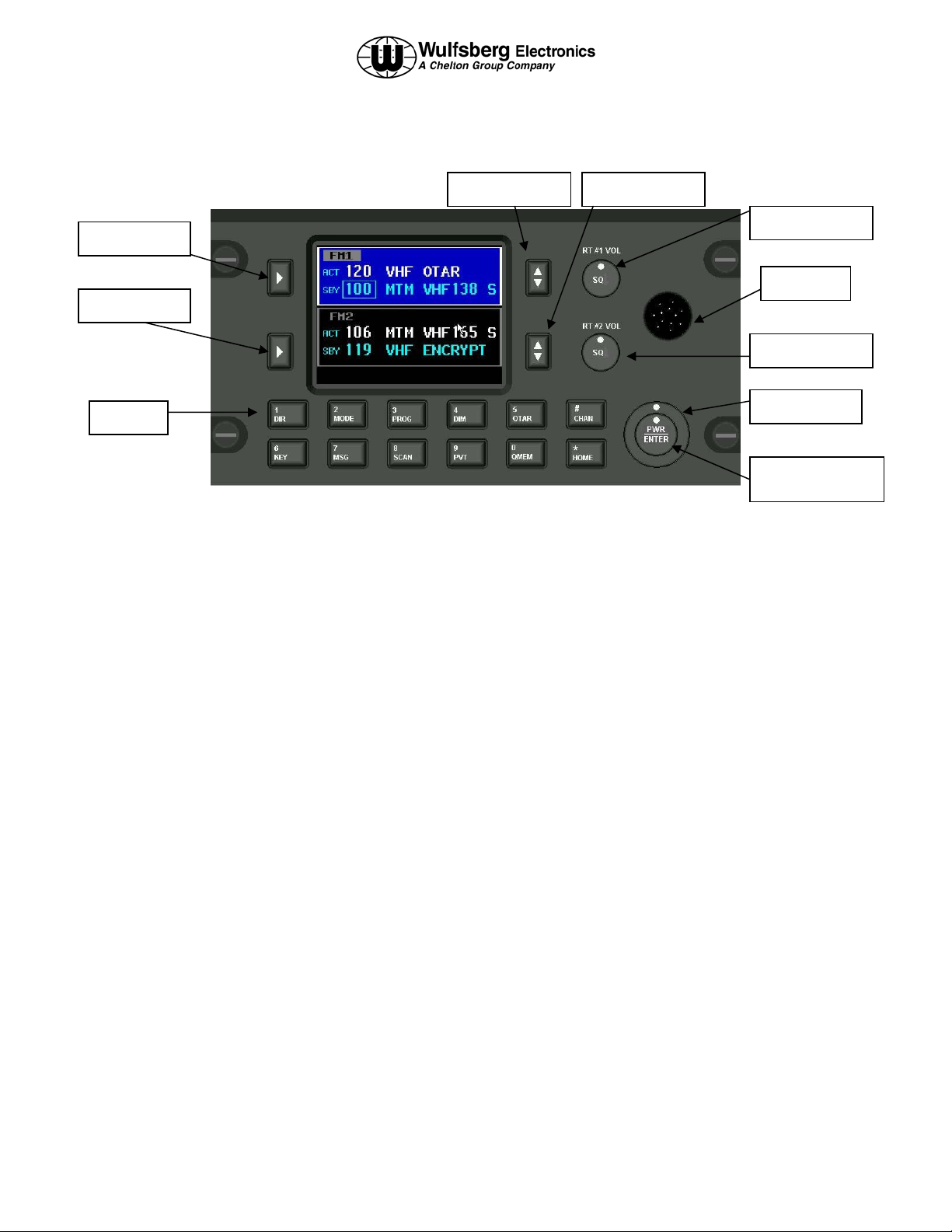
Front Panel & Controls
FM #1 Select
FM #2 Select
Keypad
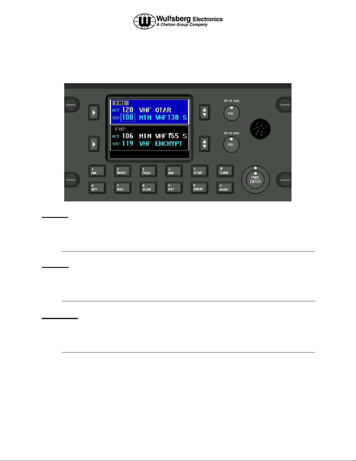
DISPLAY - The P-2000 has a color LCD display. It provides the visual feedback for the system. Exactly what is
displayed depends on the current operating mode of the P-2000. During normal operation, the top area shows
information for FM #1 and the bottom line shows information for FM #2.
The keypad and cursor/value rotary knobs perform functions on the transceiver that is highlighted in blue. The blue
highlight also indicates which transceiver has been selected for transmitting when the system is operating in
SINGLE MIC MODE. This is the mode where there is only one audio panel position being shared between the two
transceivers.
FM #1 SELECT – This button selects FM #1 as the
active transceiver. This is depicted on the display by
the FM1 area turning a bright blue color. The keypad
and cursor/value knobs will now operate exclusively
on the FM1 transceiver.
FM #2 SELECT - This button selects FM #2 as the
active transceiver. This is depicted on the display by
the FM2 area turning a bright blue color. The keypad
and cursor/value knobs will now operate exclusively
on the FM2 transceiver.
FM #1 Transfer FM #2 Transfer
headset. This is used to vary volume levels of that
transceiver.
FM #2 VOLUME KNOB – This rotary switch is
used to control the volume of FM #2. Pressing the
button will perform a “Test” of the audio system by
allowing audio from that transceiver to be sent to the
headset. This is used to vary volume levels of that
transceiver.
CURSOR KNOB – This rotary switch is used to
move the cursor around the display.
FM #1 Volume
Data Port
FM #2 Volume
Cursor Knob
Value/Enter/Pwr
Kn
FM #1 TRANSFER – The button will transfer (Flipflop) the active and standby channels for FM1.
FM #2 TRANSFER – This button will transfer
(Flip-flop) the active and standby channels for FM2.
FM #1 VOLUME KNOB – This rotary switch is
used to control the volume of FM #1. Pressing the
button will perform a “Test” of the audio system by
allowing audio from that transceiver to be sent to the
Page 8 of 40 Publication No. 150-049105
Operator’s Manual Rev. C
Jul 2005
VALUE KNOB – This rotary knob is used to modify
values at the cursor position.
ENTER/PWR button – Pushing the VALUE KNOB
(Small rotary knob) button performs “Enter” and
power on/off operations.
DATA PORT – This connector is used to transfer
data between the P-2000 and Encryption Key loaders
or for loading preset channel information via the
Motorola CPS software (PC based).
Page 9
P-2000/C-2000/RT-2000
OPERATOR’S MANUAL
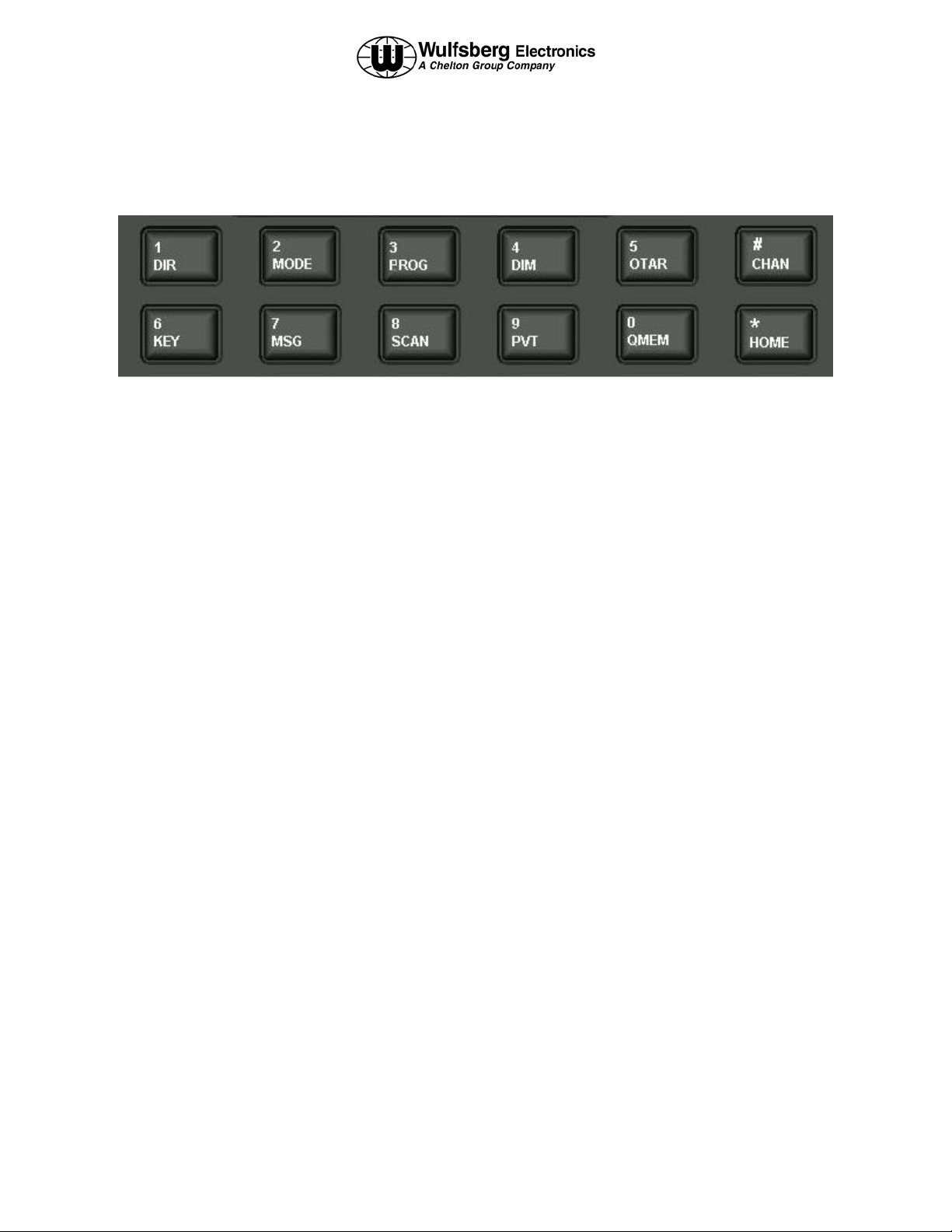
Keypad Buttons
The P-2000 has a 12 button keypad. Each button’s functions are described below.
1:DIR Toggles the active transceiver in and out of
DIRECT mode. Use this button to enter a “1” during
keypad entry mode.
2:MODE This button will cycle through the
enhanced modes of operation. Use this button to
enter a “2” during keypad entry mode.
3:PROG This button will display the PROGRAM
PAGE. Use this button to enter “3” during keypad
entry mode.
4:DIM This button will display the page used to
control the display’s brightness. Use this button to
enter a “4” during keypad entry mode.
5:OTAR This button will initiate an “Over The Air
Rekey” for the transceiver under cursor control . Use
this button to enter a “5” during keypad entry mode.
#:CHAN This button will select channel entry mode
using the keypad. Use this button to enter a “#”
during keypad entry mode.
6:KEY This button will prompt the user for a
transmit encryption key to override the preset value
for the active transceiver. Use this button to enter a
“6” during keypad entry mode.
7:MSG This button will allow the user to view
system messages pages. Use this button to enter a “7”
during keypad entry mode
8:SCAN The SCAN function is not available at this
time.
9:PVT This button will toggle the active transceiver
in and out of private mode. Use this button to enter a
“9” during keypad entry mode.
0:QMEM This button allows the user to quickly
select a preset channel using the Quick Memory
channel entry mode. Use this button to enter a “0”
during keypad entry mode.
*:HOME This button will display the HOME PAGE,
except in some advanced modes of operation, where
it will return the user to a previous page or mode of
operation. Use this button to enter a “*” during
keypad entry mode.
Publication No. 150-049105 Page 9 of 40
Rev. B Operator’s Manual
Dec 2004
Page 10
P-2000/C-2000/RT-2000
OPERATOR’S MANUAL
The Home Page
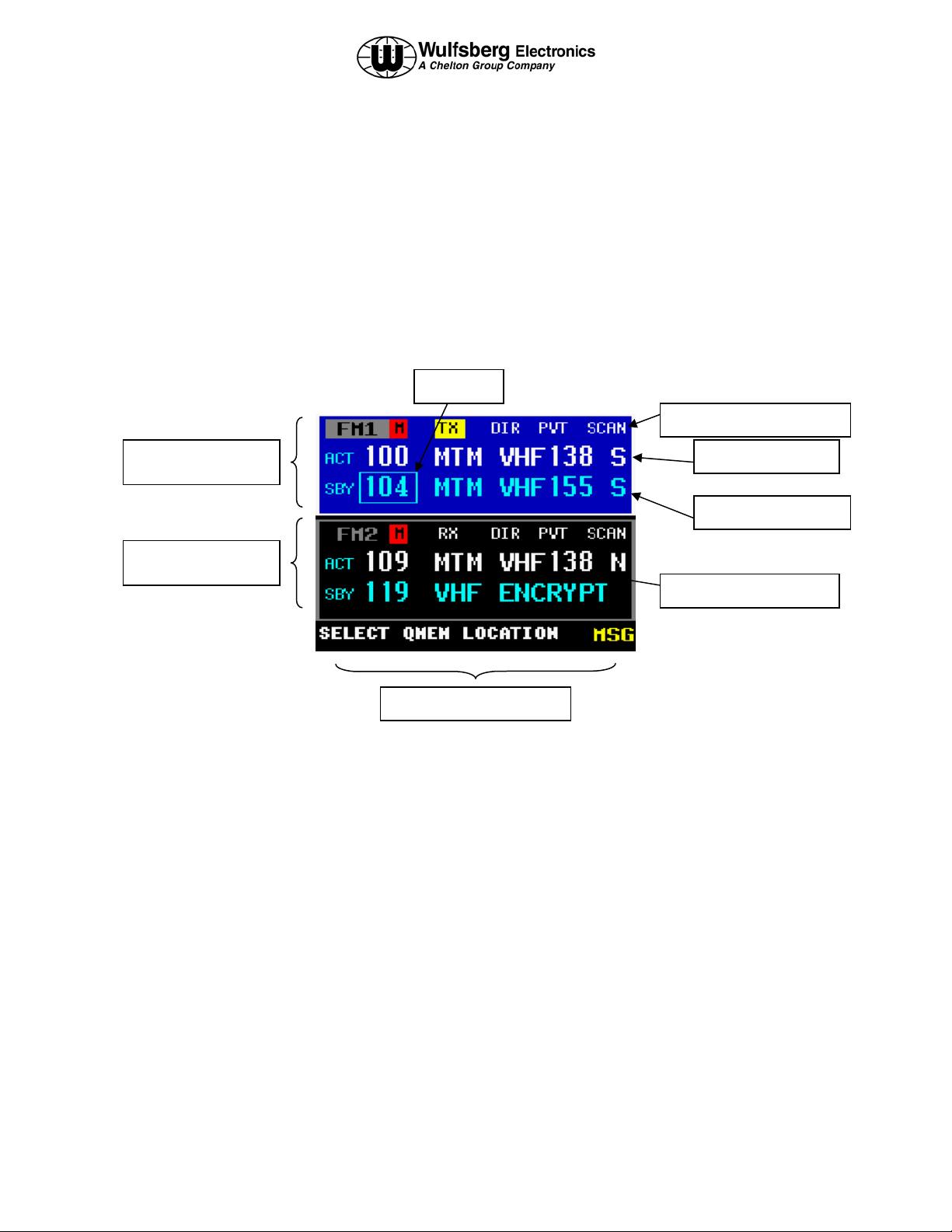
The HOME PAGE is the primary operational page of the P-2000. The HOME PAGE becomes visible when the P2000 is ready for user input, immediately after the power up and initialization sequences have completed. When
viewing the HOME PAGE, Radio 1 (Also called FM1 or transceiver #1) is always displayed on the top section.
Radio 2 is always displayed on the bottom section. All keypad-initiated operations are performed on the active
radio. The active radio easily distinguished by the bright blue color. The cursor is the square box that is located
either around the channel number or around the channel alpha identifier. It can be quickly toggled between the
channel number and alpha identifier using the cursor knob.
The following illustration is an example of what the HOME PAGE looks like.
FM 1 Information
FM 2 Information
The home page is divided into 3 areas – FM 1 information (top), FM 2 information (middle), and an area for system
status or system prompts (bottom). In the picture above notice that the area in blue contains the information for FM
1. FM 1 will always be on the top. The names “FM1”, “FM2” can be changed in the system setup so that users can
change it to something more meaningful like “VHF”, or “MAIN”.
CURSOR
FM 1 Discreet Indicators
ACTIVE Channel
STANDBY Channel
Channel Alpha Identifier
System Status Information
ACT/SBY - The normal operating mode of the P-2000 is very similar to most ATC COMM radios. The user tunes
the Standby channel and then “Flip-flops” it into the Active channel position using the TRANSFER button. The
radio is loaded with Active channel. The standby channel is ONLY used as a scratchpad for selecting the next
channel.
As an alternative to using the ACTIVE/STANDBY mode, the operator can press and hold the transfer button for 3
seconds and the STANDBY channel will disappear and now the user can tune the active channel directly. Either
mode can be selected in the System Setup Mode as the default mode of operation.
Notice the square box (CURSOR) around the SBY channel number 104. This indicates the system will tune the
Standby channel number. The cursor can be moved around the alpha identifier and channels will be selected
alphabetically using the Alpha Identifier.
Page 10 of 40 Publication No. 150-049105
Operator’s Manual Rev. B
Dec 2004
Page 11
P-2000/C-2000/RT-2000
OPERATOR’S MANUAL
STATUS LINE - The status line is located on the very bottom of the display and it is where the user will be
prompted to either input more information via the keypad, or where the Message Indictor will show there is a system
message to view. In this case the user should push the MSG button to show the Message page.
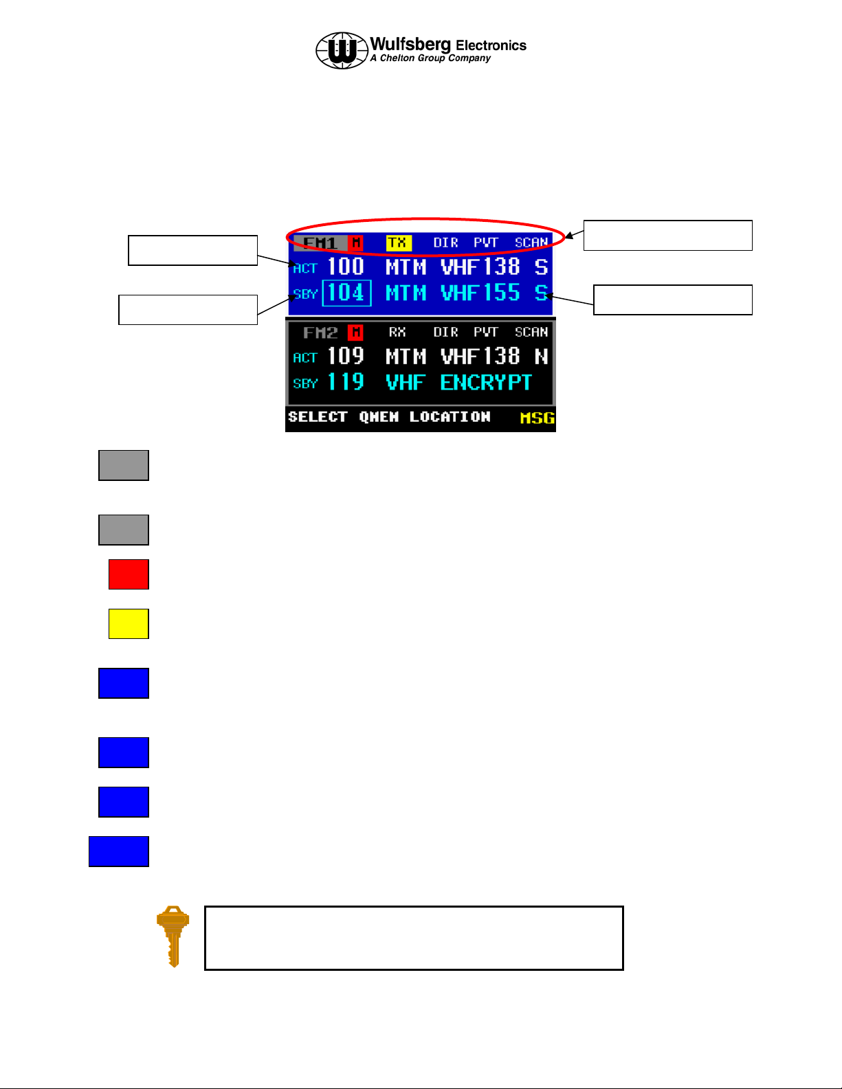
Discreet Indicators – The following discreet indicators apply to both FM1 and FM2.
FM 1 Discreet Indicators
ACTIVE Channel
STANDBY Channel
FM1
This helps the user know the information in this block is for the transceiver located in FM #1 Position.
FM1
M
This helps the user know the information in this block is for the transceiver located in FM #1 Position.
This indicates that the audio for that transceiver has been turned off, or “muted”. To un-mute the audio,
change the volume on that radio to something other than “0”.
TX
This indicates the transceiver is in the transmit mode.
RX
This indicates the transceiver is receiving a signal.
Channel Alpha Identifier
DIR
PVT
SCAN
This indicates the transceiver has been put into DIRECT mode. Direct mode is also called “Talkaround”, “Car-to-Car”, or “Simplex”.
This indicates the transceiver has been put into Private mode and will use the encryption system
embedded in the transceiver. This mode is not available if a channel is not programmed for encryption.
This indicates the transceiver has been put into Scan mode.
You can always get back to the HOME PAGE by pressing the HOME
button one or more times.
Publication No. 150-049105 Page 11 of 40
Rev. C Operators Manual
July 2005
Page 12
P-2000/C-2000/RT-2000
OPERATOR’S MANUAL
Turning the System On and Off
To power-on the P-2000, press and hold the PWR button (push in the VALUE Knob) for approximately one second
and release. Several version number and copyright pages appear on the display while the unit performs a self-test
and initializes the attached radio systems. When initialization is complete, the HOME PAGE will appear on the
display. (-XX = latest software mod)
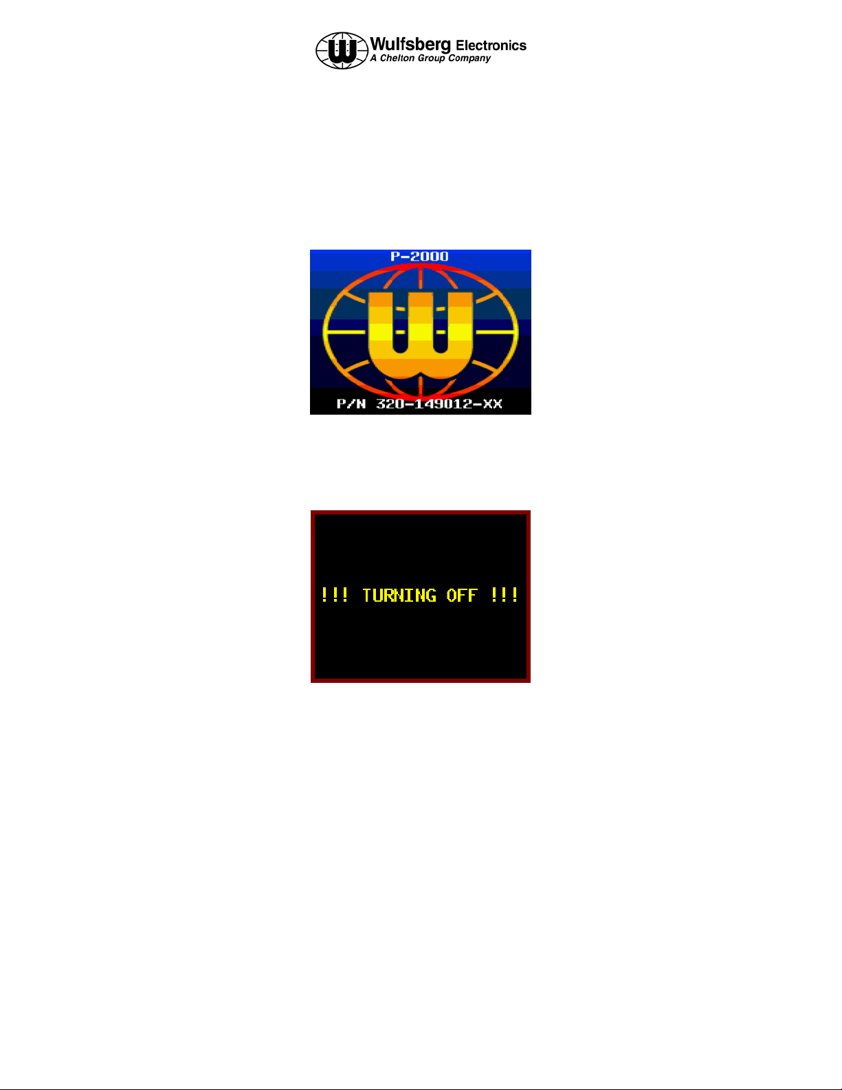
To power the P-2000 OFF, press and hold the PWR button for 3 seconds. The following message flashes on the
display several times:
Continue to hold the PWR button until the message stops flashing and the display turns off.
If aircraft power is removed while the P-2000 is in operation, the P-2000 will store the following information to
memory so that when power is re-applied the system will be at the same operating point:
1. Current active and standby channels for FM1 and FM2.
2. Current volume levels for FM1 and FM2.
If the operator releases the “PWR” button prior to 3 seconds elapsing, the display will return its previous state.
Page 12 of 40 Publication No. 150-049105
Operator’s Manual Rev. B
Dec 2004
Page 13
P-2000/C-2000/RT-2000
OPERATOR’S MANUAL
Setting the Display Brightness
When the user presses the DIM button, the display brightness adjustment display appears. When the value knob is
turned clockwise, the display brightness increases in intensity. When the value knob is turned counter clockwise,
the display brightness decreases in intensity. The Brightness display disappears when no value knob activity has
been present for more than 2 seconds.
Setting the Volume Level
When you first power on the P-2000, the volume levels for both transceivers will be reset to the level that was active
when the unit was powered down. You can change the volume level as follows.
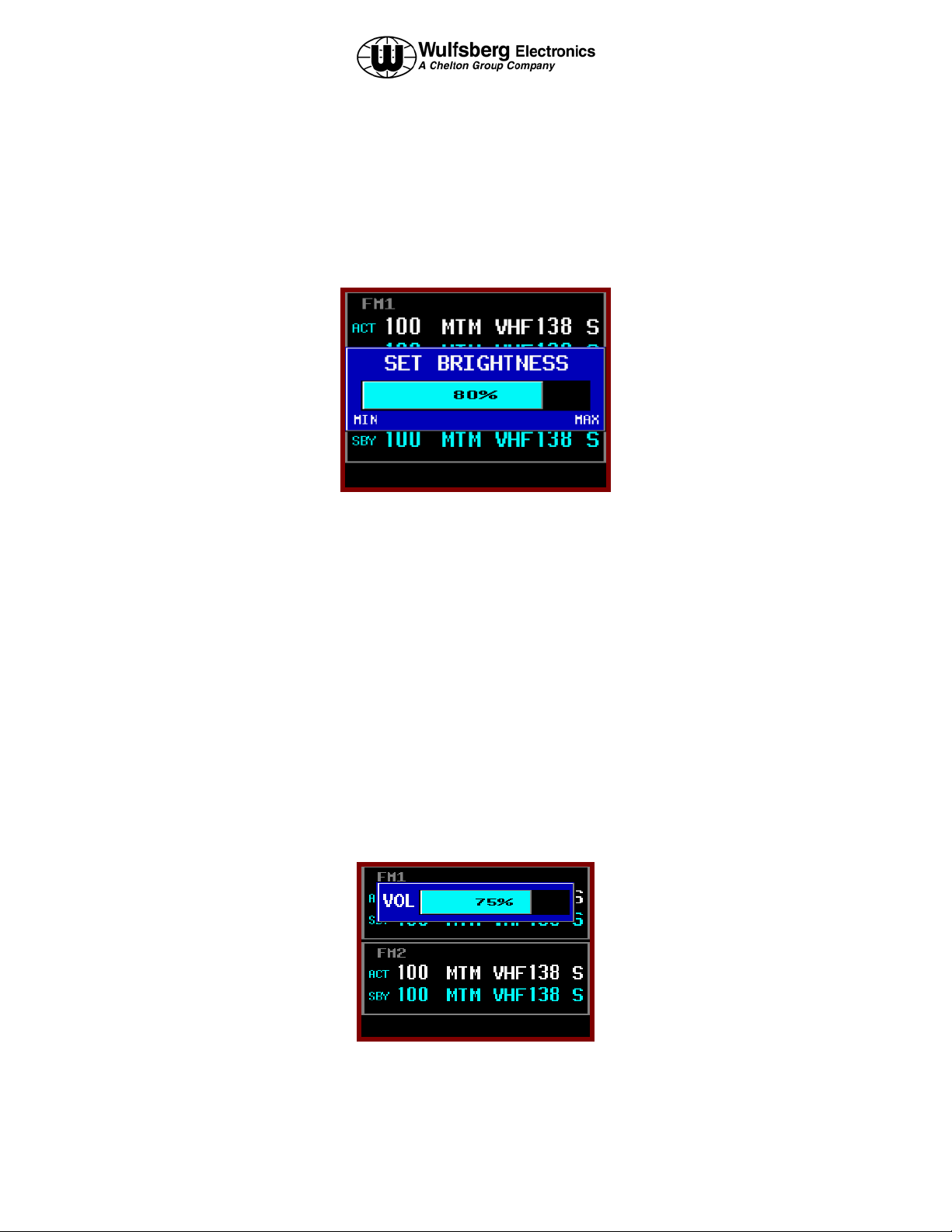
When the user turns either of the volume knobs, the volume adjustment display will appear. When the upper
volume knob is turned, the volume adjustment display will appear on the upper half of the screen, and will adjust the
volume on FM1 transceiver. Likewise, when the lower volume knob is turned, the volume adjustment display will
appear on the lower half of the screen, and will adjust the volume on FM2 transceiver. The display below depicts
the volume adjustment display when the upper volume knob has been turned. Turning the volume knob clockwise
will increase the volume level, while turning the knob counter clockwise will decrease the volume level. The
current volume level will be displayed within the display. If the volume is turned all the way down to the off
position, the bar will turn red and the Mute indicator will be displayed on the main page.
To test the current volume level, press the volume knob and noise should be heard in the headset. The volume
adjustment display will automatically disappear if when no knob turning activity has occurred for more than 2
seconds.
Publication No. 150-049105 Page 13 of 40
Rev. C Operators Manual
July 2005
Page 14

P-2000/C-2000/RT-2000
OPERATOR’S MANUAL
Selecting the Active Transceiver
To make FM1 or FM2 the “active transceiver” means that the keypad/rotary knobs will perform operations on that
transceiver. The active transceiver is always highlighted in a bright blue color. As shown in the picture below, FM1
is the active transceiver.
FM #1 Select
To make FM1 the active transceiver, push the FM #1 SELECT BUTTON as shown above. Pushing the FM #2
select button will make FM2 the active transceiver and the blue highlight will be moved to the FM2 area of the
display as shown below.
FM #2 Select
When the P-2000 is operating in SINGLE MIC MODE (only one headset shared between two transceivers), the
active transceiver is the one that will be used for transmitting. In Single Mic Mode, the transceivers (FM1 and FM2)
will have their receive audio summed together and sent to Headset #1. The operator must choose which transceiver
will be used when they want to transmit.
Page 14 of 40 Publication No. 150-049105
Operator’s Manual Rev. B
Dec 2004
Page 15

P-2000/C-2000/RT-2000
OPERATOR’S MANUAL
Selecting a Standby Channel Using the Cursor/Value Knob
When the P-2000 first powers on, the selected channels will be set to those that were active when the unit was
powered down. To select a different preset channel, do the following:
Using the cursor knob, put the square cursor around the channel number. Turn the value knob until the channel is
your desired channel. If you wish to make this your active channel, push the transfer button.
Selecting a Channel Using the Keypad
Occasionally, it is desirable to select a preset channel by entering its number via the keypad, rather than dialing it in
with the cursor/value knobs. This can be performed as follows.
When the user presses the CHAN key, the keypad channel entry mode will begin. This mode allows the user to tune
a channel by inputting the desired channel’s number into a field via the keypad. The figure below depicts this mode
of channel tuning. If no keypad input is received for more than 4 seconds, the operation will automatically cancel.
If the user presses the HOME key, the operation will also cancel. When the user presses the ENTER key, the
channel with the number input into the field will be loaded. If the input channel number is invalid, an error tone will
sound, and the previous “good” channel will be reinstated.
Publication No. 150-049105 Page 15 of 40
Rev. C Operators Manual
July 2005
Page 16

P-2000/C-2000/RT-2000
OPERATOR’S MANUAL
Selecting a Channel by Alphanumeric Identifier
To change the standby channel using the alpha identifier, use the cursor knob to move the cursor square around the
alpha identifier as shown below. Turn the value knob until the channel is your desired channel. Notice that
channels change alphabetically.
Using the Direct/Repeat Feature
The P-2000 supports both direct and repeat modes of operation. Any preset channel that has identical transmit and
receive frequencies is considered a direct channel. If the transmit and receive frequencies are different, the P-2000
considers the channel a repeater channel. Repeater channels can be temporarily changed into direct channels by
pressing the DIR button. This will temporarily copy the receive frequency into the transmit frequency. The direct
mode indicator will light. The following illustration shows radio 1 in direct mode.
NOTE:
It can take several seconds for the direct operation to be completed once the button has been
pressed.
Direct Mode Indicator
Page 16 of 40 Publication No. 150-049105
Operator’s Manual Rev. B
Dec 2004
Page 17

P-2000/C-2000/RT-2000
r
r
OPERATOR’S MANUAL
Receiving/Transmitting
Transmitting
To transmit on a radio system, select the appropriate source on your audio panel, and key the microphone.
Transmission will begin on the radio’s currently selected Active channel. During the transmission, the radio’s
transmit indicator will light, and the channel’s transmit frequency will be displayed. The following illustration
depicts FM #1 transmitting.
Receiving
The P-2000 is constantly monitoring its radios for reception. When a signal is received, the P-2000 will light the
receive indicator for the receiving radio, and route the audio to the operator’s headset (Assuming the associated
intercom switch is selected). The following illustration depicts FM #2 receiving.
TX Indicato
RX Indicato
Enabling/Disabling Transceivers
Transceivers cannot be individually powered off on the P-2000, however the volume level of either transceiver can
be reduced to zero, effectively turning off the transceiver. The screen below shows what the display looks like when
the audio level of a transceiver is set to zero. Notice the mute indicator is displayed and the level indicator turns red.
Publication No. 150-049105 Page 17 of 40
Rev. C Operators Manual
July 2005
Page 18

P-2000/C-2000/RT-2000
OPERATOR’S MANUAL
QMEM Operations
When the user presses the QMEM key, the system will enter the QMEM mode. This mode allows the user to either
select or program a QMEM location. When the user presses the QMEM key, then presses a keypad key (0-9), the
channel programmed into the corresponding (0-9) QMEM location shall be loaded into the active channel, and the
previously active channel shall be loaded into the standby channel. If the user presses the QMEM key, then presses
and holds down a keypad key (0-9) for 3 or more seconds, the current active channel shall be programmed into the
corresponding QMEM location. Should the user not press any key for more than 4 seconds after pressing the
QMEM key, the QMEM operation shall automatically be canceled. The user can cancel the QMEM operation by
pressing the HOME key. The figure below shows the QMEM operation in mid stream.
To store a channel into a QMEM position first put the desired channel in the active channel and press the QMEM
button. The figure below shows what the display will look like.
At this point press and hold button 0-9 until the status line indicates the storage operation is completed, as shown in
the picture below:
To load the active channel using QMEM, simply push the QMEM button followed by a 0-9 button and the
programmed channel will be automatically loaded into the active channel. If that QMEM position has not been
programmed with a channel, the status line will indicate to the user no channel is programmed.
Page 18 of 40 Publication No. 150-049105
Operator’s Manual Rev. B
Dec 2004
Page 19
P-2000/C-2000/RT-2000
OPERATOR’S MANUAL
MESSAGE PAGE
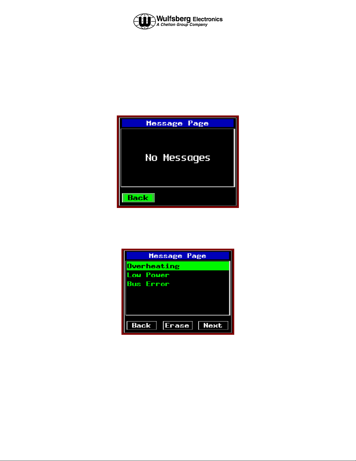
This page allows the user to manage text messages for the system. When no unread messages exists within the
system, the MSG indicator will not be visible on the normal operation page. When the MSG key is pressed on the
normal operation page and no messages are available, the no message page is displayed. This page is depicted
below. The only selectable item on this page shall be the back button. Pressing ENTER will return to the HOME
page.
When an unread message exists within the system, the MSG indicator will be visible on the HOME page. When the
MSG key is pressed and messages are available, the message list page shall be displayed. An example of a message
page that contains unread messages is shown below.
Publication No. 150-049105 Page 19 of 40
Rev. C Operators Manual
July 2005
Page 20

P-2000/C-2000/RT-2000
OPERATOR’S MANUAL
The cursor knob allows the selection of the message list, back button, erase button, and next button. Pressing
ENTER while the back button is selected returns to the previous page. Pressing ENTER while the erase button is
selected deletes the currently selected message from the message list. Pressing ENTER while the next button is
selected invokes the message view page for the currently selected message in the message list. The message view
page is depicted below
You can always get back to the HOME PAGE by pressing the HOME
button one or more times.
Page 20 of 40 Publication No. 150-049105
Operator’s Manual Rev. B
Dec 2004
Page 21
P-2000/C-2000/RT-2000
OPERATOR’S MANUAL
Programming/Editing a Preset Channel
The EDIT PAGE allows the operator to temporarily change properties of a preset channel. Precisely which
properties can be changed varies with channel and radio type At a minimum, all information that can be determined
by the system during the LEARN mode is displayed on this page.
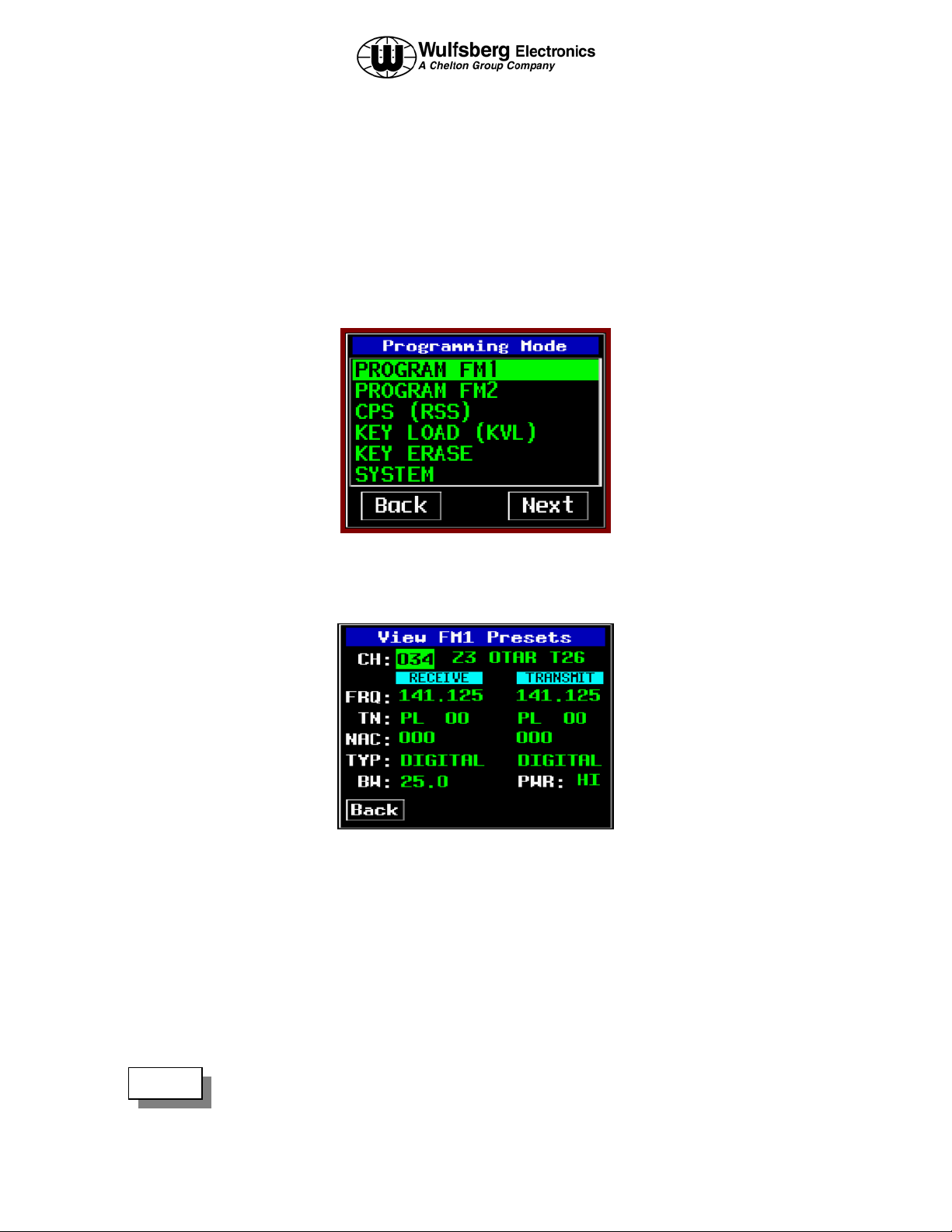
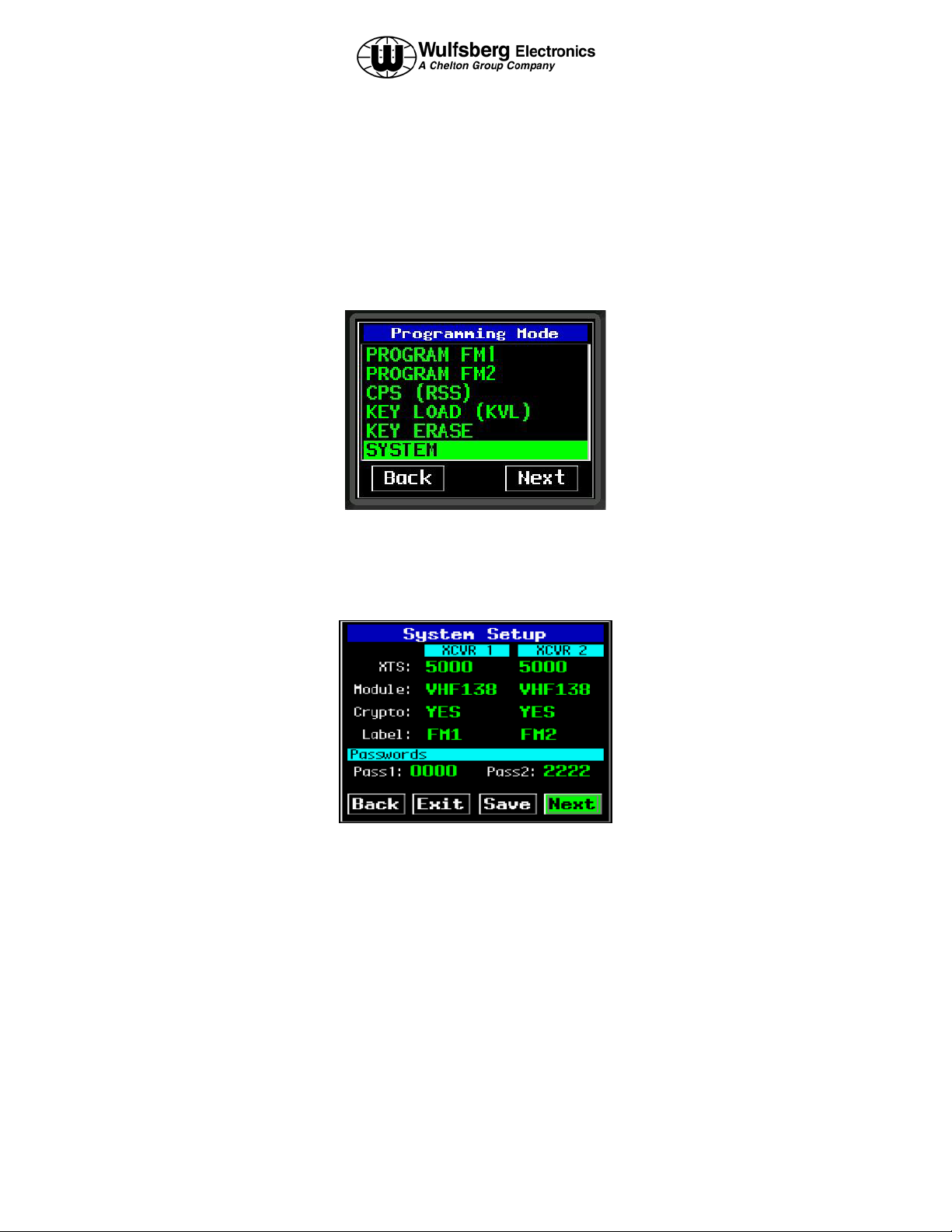
While on the HOME page press the PROG button and Programming Mode display page will be seen.
Select either of the first two options to program/edit preset channels for FM1 or FM 2 transceivers. Once a selection
has been made the display will show the Channel Properties page will be displayed as seen below:
On this page field labels are shown in white characters and data fields are in green characters. The cursor/value
knobs are used to move the cursor to the different fields and then changes and/or data entered via the value knob.
Below is a list of the data fields used on this display page:
Channel Identifier Field (CH:) – This displays the channel number and ALPHA ID of the currently selected
channel, i.e. the channel you are editing.
Transmit Power Level Field (PWR:) – This field displays the current channel’s transmit power level. Power level
is displayed as HI for high power or LO for low power.
NOTE:
Publication No. 150-049105 Page 21 of 40
Rev. C Operators Manual
July 2005
The following fields, while currently displayed, are not active and will not contain
accurate information as of software revision 4.
Page 22

P-2000/C-2000/RT-2000
OPERATOR’S MANUAL
Frequency Fields (FRQ:) – These fields display the current channel’s receive and transmit frequencies.
Tone Fields (TN:) – These fields display the current channel’s transmit and receive CTCSS/DCS (PL/DPL) tones.
NAC Code Fields (NAC:) – These fields display the current channel’s transmit and receive NAC codes used on
P-25 systems.
Type Fields (Type:) – This field displays whether the channel is Analog, Digital, or Mixed (Analog and Digital).
Bandwidth Field (BW:) – This field displays the currently selected channel’s bandwidth in kHz.
Editing a Preset Channel
Currently only changing of the transmit power is allowed for editing a preset channel.
Changing Transmit Power
The P-2000 supports the selection of high and low transmit power. Normally high power is used, however, if
interference or other transmit issues are experienced, low power may be selected to help remedy the issue. You can
alter the transmit power setting from the EDIT PAGE as follows.
Move the cursor under the transmit power field.
Rotate the VALUE knob clockwise once. The power indicator will toggle between high and low with each turn of
the VALUE knob.
Press the HOME button or the BACK button to exit the mode and return to the normal operating page.
Page 22 of 40 Publication No. 150-049105
Operator’s Manual Rev. B
Dec 2004
Page 23

P-2000/C-2000/RT-2000
OPERATOR’S MANUAL
Enhanced System Features
Relay Mode
Relay Mode allows your aircraft’s P-2000-based transceiver system to automatically relay receiver audio from one
transceiver and retransmit it out the opposite transmitter. If a Relay Mode link is established between two locations,
a message received from one location is automatically retransmitted to the other. You can establish relay operation
as follows.
• From the HOME page select the desired channel for FM1.
• From the HOME page select the desired channel for FM2..
• Press the MODE button and the Mode Selection page will be displayed:
• Select the RELAY MODE by high-lighting the option and pressing the ENTER button. The unit will now enter
the RELAY mode and the display will look like the one below:
Publication No. 150-049105 Page 23 of 40
Rev. C Operators Manual
July 2005
Page 24

P-2000/C-2000/RT-2000
OPERATOR’S MANUAL
Simulcast Mode
Simulcast Mode allows you to transmit simultaneously to two locations that have radios tuned to different
frequencies. You can establish simulcast operation as follows.
• From the HOME page select the desired channel for FM1.
• From the HOME page select the desired channel for FM2.
• Press the MODE button and the Mode Selection page will be displayed:
• Select the SIMULCAST MODE by high-lighting the option and pressing the ENTER button. The unit will now
enter the SIMULCAST mode and the display will look like the one below:
• Use either RT1 or RT2 mic position on the audio selector panel and initiate a transmission. Both Radios will
transmit at the same time.
• To exit the SIMULCAST MODE, simply press the HOME button.
Page 24 of 40 Publication No. 150-049105
Operator’s Manual Rev. B
Dec 2004
Page 25

P-2000/C-2000/RT-2000
OPERATOR’S MANUAL
Relay/Simulcast Mode
Relay-Simulcast mode combines the functions of Relay Mode and Simulcast Mode. It allows you to establish an
automatic radio link with two other locations that have radios tuned to different frequencies in different frequency
bands, and allows you to transmit to those same locations simultaneously. You can establish relay/simulcast
operation as follows.
• From the HOME page select the desired channel for FM1.
• From the HOME page select the desired channel for FM2.
• Press the MODE button until the following display page appears.
• Select the RELAY/SIMULCAST MODE by high-lighting the option and pressing the ENTER button. The unit
will now enter the RELAY/SIMULCAST mode and the display will look like the one below:
• Now the unit will RELAY between FM1/FM2 and it will also SIMULCAST on both transceivers when the
operator chooses either FM1 or FM2 audio panel positions.
• To exit the RELAY/SIMULCAST MODE, simply press the HOME button.
Publication No. 150-049105 Page 25 of 40
Rev. C Operators Manual
July 2005
Page 26

P-2000/C-2000/RT-2000
OPERATOR’S MANUAL
Repeater Mode
Repeater mode is not a specific mode of the P-2000 but an airborne repeater can effectively be created by
preprogramming specific channels and then using the RELAY MODE. It is also necessary for the two transceivers,
FM1 and FM2 to use the same band. In other words, you cannot perform a repeater function with a P-2000 that has
FM1 operating in the 137-174 MHz band and FM2 operating in the 800 MHz band.
Say a P-2000 channel normally uses a repeater that is not working and an area is without communications on that
channel. To act like an airborne repeater the operator must program a special preset channel with the receive and
transmit frequencies reversed. We suggest giving this channel a special ALPHA ID that helps the operator
recognize it as a special repeater channel associated with the original channel. To operate as an airborne repeater
perform the following steps:
• While on the HOME PAGE set the ACTIVE channel to the channel you normally use the repeater on FM1.
• Put FM1 in DIRECT MODE by pressing the DIR button.
• Select the special channel associated with the repeater on FM2.
• Go into the RELAY MODE.
• If the operator wants to talk select FM2.
You can always get back to the HOME PAGE by pressing the HOME
button one or more times.
Page 26 of 40 Publication No. 150-049105
Operator’s Manual Rev. B
Dec 2004
Page 27

P-2000/C-2000/RT-2000
OPERATOR’S MANUAL
Encryption Features
Turning Encryption On and Off
Select FM1 or FM2 depending on which transceiver you what to encrypt. Press the PVT button to toggle encryption
on and off. If the P-2000 preset channel being used has been set up for encryption, the privacy indicator will light.
PVT Indicator
NOTE:
Encryption can only be turned on for channels that have been pre-programmed with an encryption
key. Three error beeps will sound if the channel has not been setup for encryption.
Selecting an Encryption Key
The preset encryption key (sometimes called KEYMAT) for a channel can be temporarily changed as follows.
• Ensure you are on the HOME PAGE, and the radio you wish to select is active and encryption capable channel
is also selected.
• Press the KEY button. The following illustrates the display when the KEY button was pressed with radio 1
active. If the KEY button is pressed on a channel that has not been preset to use encryption, three warning
beeps will sound.
• Rotate the VALUE knob to change the encryption key. A value of “PSET” indicates you want to use the
channel’s preset encryption key. A numeric value (1-16) indicates you want to override the preset key with the
specified key.
Publication No. 150-049105 Page 27 of 40
Rev. C Operators Manual
July 2005
Page 28
P-2000/C-2000/RT-2000
OPERATOR’S MANUAL
• Press the ENTER button to accept the displayed key. The display will return to the HOME PAGE.
• When transmitting, and if encryption keys are properly loaded, a tone at the start of the transmission will be
generated by the radio and heard by the operator. Begin speaking AFTER the tone or part of your transmission
will be lost.
• When transmitting in the encrypted mode, if you hear a continuous warble tone, this indicates that the
encryption key(s) have not been loaded. Either manually enter encryption keys or perform an OTAR if your
system has that capability.
• The newly selected KEYMAT WILL REMAIN even if the channel is changed in effect until power down.
Performing an OTAR
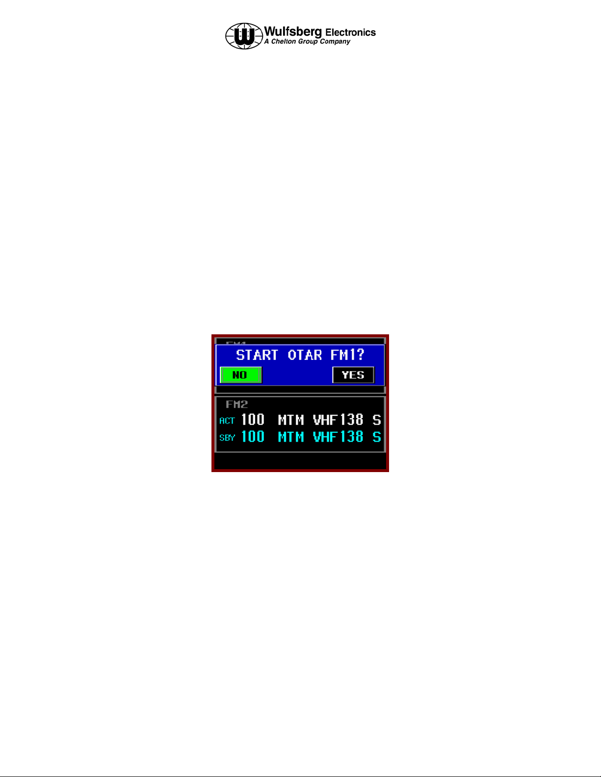
• Ensure you are on the HOME PAGE, and the cursor is on the line of the radio you wish to select and an OTAR
capable channel is also selected.
• Press the OTAR button. The following illustrates the display when the OTAR button was pressed with radio 1
under cursor control.
• To confirm the start of the OTAR, select YES and press the ENTER button to initiate the OTAR process. The
status of the OTAR will be displayed on the radio’s display line. Status messages include “OTAR
REQUESTED”, “OTAR IN PROGRESS”, “OTAR ABORTING”, “OTAR COMPLETE”, and “OTAR
FAILED”.
Page 28 of 40 Publication No. 150-049105
Operator’s Manual Rev. B
Dec 2004
Page 29

P-2000/C-2000/RT-2000
OPERATOR’S MANUAL
The following illustrates the display with an OTAR in progress.
NOTE:
The OTAR process will automatically time-out after 2 minutes of unsuccessful OTAR attempts.
At anytime during the OTAR operation, or after the OTAR has completed, whether successfully or unsuccessfully,
the user must press the OTAR or HOME key to cancel/exit the OTAR operation. Doing so shall display the OTAR
cancel confirmation page, as depicted below. This page functions identically to the OTAR start confirmation page.
You can always get back to the HOME PAGE by pressing the HOME
button one or more times.
Publication No. 150-049105 Page 29 of 40
Rev. C Operators Manual
July 2005
Page 30

P-2000/C-2000/RT-2000
OPERATOR’S MANUAL
Loading Encryption Keys
Before a transceiver will transmit encrypted messages, the user must load encryption keys into the transceiver. To
accomplish this, the user must first put the transceiver into KEY LOAD mode, and then using a Motorola KVL, load
the keys. Perform the following steps to load keys:
• From the HOME page press the PROG button. If prompted, enter the password #1 (In the system programming
options, the user has the option of eliminating this password by setting it to “0000”)
• Highlight the KEY LOAD option and press ENTER. Enter password #2 to get to the Transceiver Setup page.
• In the XCVR field, select which transceiver (FM1 or FM2) to load keys.
• Highlight the START option and press the enter button to begin the encryption load process.
• Connect the KVL loader to the data port on the front of the P-2000 (or RT-2000, not the C-2000). Load keys
for both FM1 and FM2 if desired. The key loader will indicate successful loading.
• Highlight the STOP option and press the enter button to end the encryption load process. This will cause the
system to briefly display a splash screen indicating that the system is busy.
• The unit will display a dialog box indicating that it needs to be restarted, highlight YES and press the enter
button to restart the unit.
Page 30 of 40 Publication No. 150-049105
Operator’s Manual Rev. B
Dec 2004
Page 31

P-2000/C-2000/RT-2000
OPERATOR’S MANUAL
Erasing Encryption Keys With A Key loader
It may be desirable to erase the encryption keys contained in a P-2000 transceiver. For example, prior to sending the
unit in for service. This can be accomplished as follows.
• Ensure you are on the HOME PAGE, and the cursor is on an encryption capable channel.
• Press the PROG button. If prompted, enter the password #1 (In the system programming, the user has the
option of eliminating this password by setting it to “0000”)
• When prompted, enter the password #2 and the Transceiver Setup page will be displayed as below:
• In the XCVR field, select which transceiver (FM1 or FM2) to erase keys.
• Highlight the START option and press the enter button to erase the encryption keys.
• Upon completion of the process the unit will display a dialog box indicating that it needs to be restarted,
highlight YES and press the enter button to restart the unit . After the unit restarts, verify that the keys have
been erased by attempting to transmit on an encryption channel with PVT on. The transceiver will provide an
audio tone to indicate encryption keys have been erased.
Publication No. 150-049105 Page 31 of 40
Rev. C Operators Manual
July 2005
Page 32

P-2000/C-2000/RT-2000
OPERATOR’S MANUAL
CPS MODE
Loading Channel Memory
Programming the preset channels of the P-2000 must be performed with PC based program available from
MOTOROLA named CPS. Normally this procedure is accomplished by a technician familiar with this software
package since extensive knowledge is required to operate the Motorola software. As a note to the technician, no
RIB box is required between the PC and P-2000 since Wulfsberg has built this capability into its transceiver.
Please understand there are very specific requirements for the Motorola
module to function properly:
1. Zones must be set for a maximum of 16 channels per zone.
2. Do not use scan on any personality.
3. Do not change the button settings or menu items. Leave them to the
factory defaults.
4. Disable all messages such as display encryption key name on mode
change.
5. Do not have multiple programs operating on your computer that use the
same communication port as the Motorola CPS software.
6. Do not use identical channel names within the same zone.
Please review the P-2000 FAQ page on the Wulfsberg
website (www.wulfsberg.com) for the latest program
information.
* NOTE If programming a system that contains a C-2000, turn off the
C-2000 until the P-2000 has been successfully programmed.
Page 32 of 40 Publication No. 150-049105
Operator’s Manual Rev. B
Dec 2004
Page 33
P-2000/C-2000/RT-2000
OPERATOR’S MANUAL
The process to read and modify the transceiver preset channels is as follows:
• Ensure you are on the HOME PAGE.
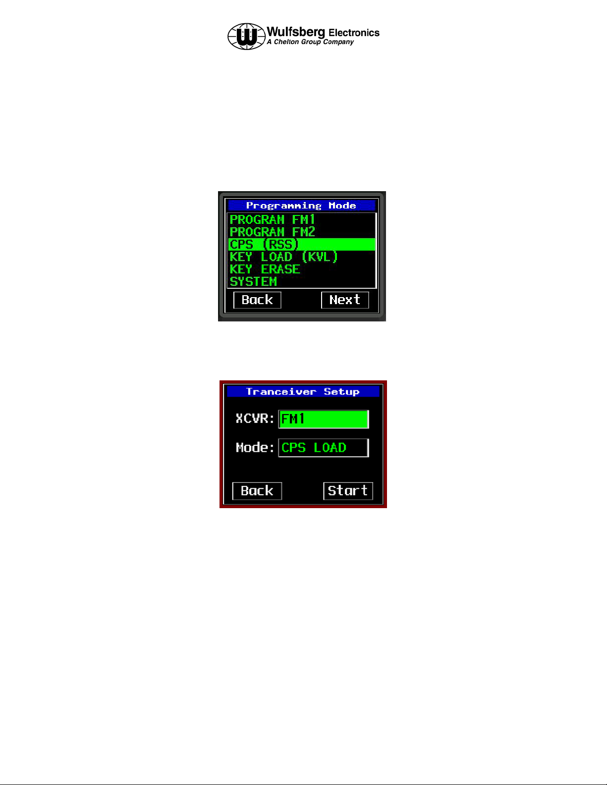
• Press the PROG button. If prompted, enter the password #1 (In the system programming, the user has the
option of eliminating this password by setting it to “0000”). The PROGAM page will be displayed as below:
• Highlight the CPS option and press the enter button. The Transceiver Setup page will be displayed with the
CPS load already pre-selected as shown below:
• Select XCVR FM1 or FM2, highlight the start option and press enter to begin.
• Connect the PC to the data port on the front of the P-2000(RT-2000 not C-2000).
• Using the CPS software, read the FM1 and save the file as sent by the Wulfsberg Factory for backup purposes.
• Perform any changes to the archive file such as adding/deleting channels, changing encryption options etc. For
the P-2000 to function properly DO NOT change key button options or display options. Also, the
Zone/Channel assignment must be made so that there no more than 16 channels per zone.
• Once all new channels have been entered, transfer the updated archive back into the P-2000. The Motorola
software will indicate successful completion of this task.
Publication No. 150-049105 Page 33 of 40
Rev. C Operators Manual
July 2005
Page 34

P-2000/C-2000/RT-2000
OPERATOR’S MANUAL
• Press the HOME button once to end the CPS Load process, this will cause the system to briefly display a
“System busy, please wait…” dialog, and will then prompt the user to enter LEARN MODE. In this mode, the
P-2000 computer interrogates the internal transceivers to determine what changes have been made and to update
its internal memory. This process can take several minutes. The operator will be shown progress as the system
completes its task. This task must be successfully performed or the P-2000 main processor will not be able to
properly function with the internal transceivers.
• Upon successful completion of the LEARN mode, the system will prompt the user to restart the system, select
YES and press enter to restart the P-2000.
• The above process must be performed for both FM1 and FM2.
You can always get back to the HOME PAGE by pressing the HOME
button one or more times.
Page 34 of 40 Publication No. 150-049105
Operator’s Manual Rev. B
Dec 2004
Page 35
P-2000/C-2000/RT-2000
OPERATOR’S MANUAL
SYSTEM SETUP MODE
The P-2000 comes from the factory already configured for a normal installation, however, there are several options
the installer can select. These options are very simple to update. The process is as follows.
Ensure you are on the HOME PAGE and press the PROG button.
• Highlight the SYSTEM option and press the ENTER button. You will be prompted to enter password #3. This
password is available only in the installation manual and cannot be set by the user. After successful entry of
password 3 the SYSTEM SETUP page will be displayed.
• On System Setup Page 1, users can configure the Label field (instead of FM1 or FM2, the user could input
VHF1, MAIN, OPS or anything that helps the operators properly select transceivers), and the passwords.
Password #1 will not appear in any operations if it set to “0000”. Do not change Module or Crypto type as
these are factory only settings.
• To display page 2, highlight the NEXT option and press enter.
Publication No. 150-049105 Page 35 of 40
Rev. C Operators Manual
July 2005
Page 36

P-2000/C-2000/RT-2000
OPERATOR’S MANUAL
• The second setup page allow the selection of the following
• Enable Standby – the active/standby channel operation can be set to active only by saying “YES” to this
option. A “NO” will eliminate the standby channel and the user will tune active channels only. Factory
default for this option is “YES”.
• Lock QMEM – To keep users from altering the QMEM settings, this option can be set to YES. Factory
default for this option is “NO”.
• Lock Volume – The volume of the headset outputs can be locked in the maximum volume position by
setting this option to “YES”. This would be used when the audio panel already has volume controls and it
would eliminate the operator from having to manipulate both the P-2000 volume knobs and the audio panel
volume knobs. Factory default for this option is “NO”.
• Mic Mode – If the audio panel connected to the P-2000 has only one position, set this option to “SINGLE”.
If the audio panel has two positions, one for FM1 and another for FM2, set this option to “DUAL”. Factory
default for this option is “DUAL”.
• To Save the changes made to the SYSTEM SETUP, highlight the “SAVE” option and press enter. The screen
will indicate saving of the data is taking place. When the data save process is complete, press the HOME button
several times until the HOME page is displayed.
You can always get back to the HOME PAGE by pressing the HOME
button one or more times.
Page 36 of 40 Publication No. 150-049105
Operator’s Manual Rev. B
Dec 2004
Page 37

P-2000/C-2000/RT-2000
OPERATOR’S MANUAL
MAINTENANCE PAGES
The following information is not normally needed by and operator. The maintenance pages are used by a technician
to make audio level adjustments and verify system operation via BITE (Built-In-Test).
• Ensure you are on the HOME PAGE and press the PROG button.
• Highlight the MAINTENANCE (It’s located below the SYTEM option) option and press the ENTER button.
You will be prompted to enter the Password #2. After successful entry of Password #2 the MAINTENANCE
mode page will be displayed as seen below.
Selectable modes shall include Flashport firmware mode, Data mode, Service port mode, Extended protocol mode,
Digital pot adjustment mode, and Software version reporting mode.
Publication No. 150-049105 Page 37 of 40
Rev. C Operators Manual
July 2005
Page 38
P-2000/C-2000/RT-2000
OPERATOR’S MANUAL
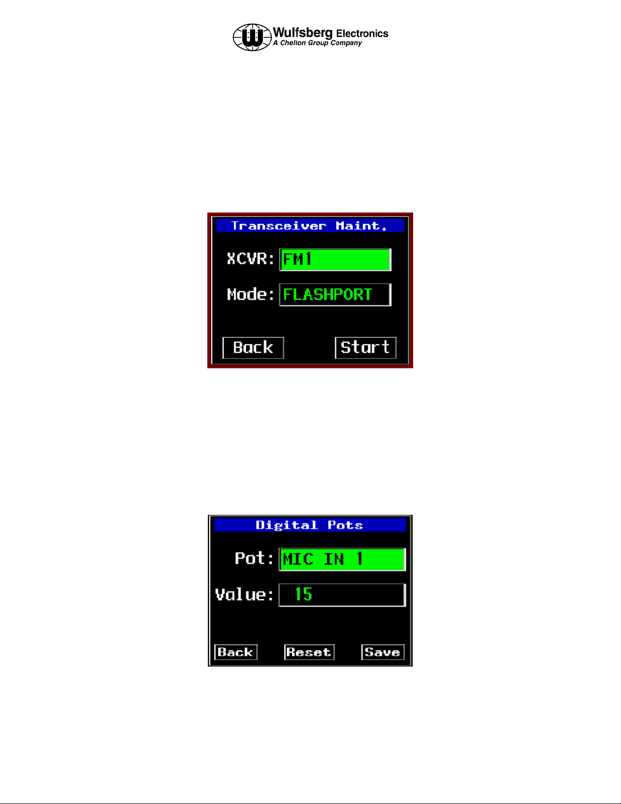
Flashport Mode
The flashport mode is one of the mode options available on the Transceiver Maintenance page. This mode allows
the technician to upgrade the embedded software within the internal transceiver.
• Select the transceiver to perform the flash upgrade. Highlight START and press enter to begin. Perform the
flash upgrade.
Data mode, WED service mode and extended protocol modes are accessed using the same procedure.
Digital Pot Tuning Mode
This page allows a technician to adjust the digital pot settings on the P-2000. The cursor knob allows the selection
of the pot name field, pot value field, the back button, and the save button. Turning the value knob while the pot
name field is selected shall enumerate all the pot names: MIC IN 1, MIC IN 2, SIDETONE 1, SIDETONE 2,
HDSET OUT 1, HDSET OUT 2, SPEAKER, and ALERT TONE. Turning the value knob while the pot value field
is selected enumerates the range of values: 0-127. The display below shows the layout for this page.
Page 38 of 40 Publication No. 150-049105
Operator’s Manual Rev. B
Dec 2004
Page 39

P-2000/C-2000/RT-2000
OPERATOR’S MANUAL
Software Versions Display Page
To view the software version of all programmed parts within the P-2000, select the Software Version page from the
MAINTENANCE MODE page.
• From the MAINTENANCE MODE page, Highlight the SOFTWARE VERSIONS option and press ENTER.
This page shall allow the user to view the part numbers and/or version numbers of the software modules installed in
the P-2000 radio system. The module versions that are reported are display board flash, CPU board internal flash,
CPU board external flash, and CPU board CPLD. Should an error occur during the query, “N/A” shall be displayed
in place of the software version. The back button will be the only selectable item on the page. Pressing the ENTER
key shall return to the previous page.
Publication No. 150-049105 Page 39 of 40
Rev. C Operators Manual
July 2005
Page 40

P-2000/C-2000/RT-2000
OPERATOR’S MANUAL
Steps to Successful Setup and Operation
While we would like to pull products out of the box and immediately start to use them, this system is one that takes
just little work to get to that point. First READ THE OPERATORS MANUAL!!!! This will familiarize you with
the buttons and display pages of the system. The following checklist will help installers setup the P-2000 or C2000/RT-2000.
1. Note all part numbers of components in your system..
P-2000 Part Number = _______________________________________
C-2000 Part Number = _______________________________________
RT-2000 Part Number = _______________________________________
Please write down the frequency bands of the transceivers inside the P-2000/RT-2000.
FM #1 = ___________________
FM #2 = ___________________
2. Using the SYSTEM Programming page 2, select whether the unit will be operated in Single Mic Mode(only one
mic/headset port) or Dual Mic Mode (two independent mic/headset ports). Review the other options and
configure as desired. Return to the HOME page.
3. Put the P-2000/RT-2000 in CPS mode for FM 1.
4. Connect a PC to the programming port of the P-2000/RT-2000 and run the Motorola CPS software.
5. Using the CPS software, read the codeplug of FM 1. Save this first in case you need to return to factory
settings.
6. Program personalities and Zones/Channels. It is very important to use good channel identifiers so operators can
efficiently determine the purpose of the channel. Whenever possible, use the same channel name the ground
units use so that when calling out channel changes both the aircraft and the ground units can use the same
channel names. These steps require significant knowledge of the Motorola software. We encourage enlisting
the help of someone familiar with Motorola CPS software to successfully program the internal transceivers.
7. Save the modified codeplug on the hard drive and then download it into FM1.
8. Do the above for FM #2 if applicable.
9. Upon the exit from CPS mode, the P-2000/RT-2000 will ask if you wish go into “LEARN” mode. If you’ve
added, deleted, or changed the archive in any way, say yes. If you just looked at the archive but didn’t change
it, then just say no. When the unit is in “LEARN” mode, the internal computer is interrogating the transceiver
module for information about channels that were programmed during CPS operations. Wait until the display
indicates successful completion of this process.
10. Turn power on and off to begin a full start process and validate that all channels programmed during CPS are
now functional on both FM #1 and FM #2 transceivers.
Page 40 of 40 Publication No. 150-049105
Operator’s Manual Rev. B
Dec 2004
 Loading...