

Page 1
Installation Manual
P-2000 and C-2000/RT-2000
Transceiver Systems
P-2000
Part Number: 400-049200-11-xxx-xxxx-xxxx
Hardware Mod: 1
C-2000
Part Number 400-049300-11-xxx-xxxx-xxxx
Hardware Mod: 1
RT-2000
Part Number 400-049400-11-xxx-xxxx-xxxx
Hardware Mod: 1
Page 2

P-2000/C-2000/RT-2000
Installation Manual
RF Exposure Information
This radio is restricted to occupational/controlled applications where users have been
made aware of the potential for exposure and can exercise control over their exposure.
Antennas used for the radio must not exceed the antenna gain shown below for each
transmit frequency range. The antenna must be installed at least or exceeding the
minimum distance away from any person(s) depending on the transmit frequency.
Frequency Max Antenna Gain Min Distance
136 – 174 MHz 0 dBi 21 cm (8.3 in)
403 - 470 MHz 3 dBi 25 cm (9.9 in)
450 – 520 MHz 3 dBi 25 cm (9.9 in)
806 – 870 MHz 3 dBi 21 cm (8.3 in)
Transmit no more than 50 % of the time. Measurable RF energy exposure occurs only
when transmitting.
Failure to observe these restrictions will result in exceeding the FCC RF exposure limits.
Page 2 of 41 Publication No. 150-049106
P-2000 Installation Manual Rev. A
Oct 2003
Page 3

P-2000/C-2000/RT-2000
INSTALLATION MANUAL
SECTION 1 – GENERAL INFORMATION
1. Introduction
This section contains information relative to the physical, mechanical, and electrical
characteristics of the Wulfsberg Electronics “2000” Family of Communications Systems.
2. Applicability
This manual applies only to the P-2000 panel mount transceiver, C-2000 control unit, and RT2000 remote mount transceiver.
3. Equipment Description
The Wulfsberg “2000” family FM Communications System is a dual transceiver FM voice
communications link between the aircraft and ground facilities. The system has not been
designed by the manufacturer to be installed on Type Certificated aircraft. Installations on these
type of aircraft are subject to applicable FAA regulations.
The “2000” family consists of the P-2000 panel mount transceiver and C-2000/RT-2000 control
and remote mount transceiver.
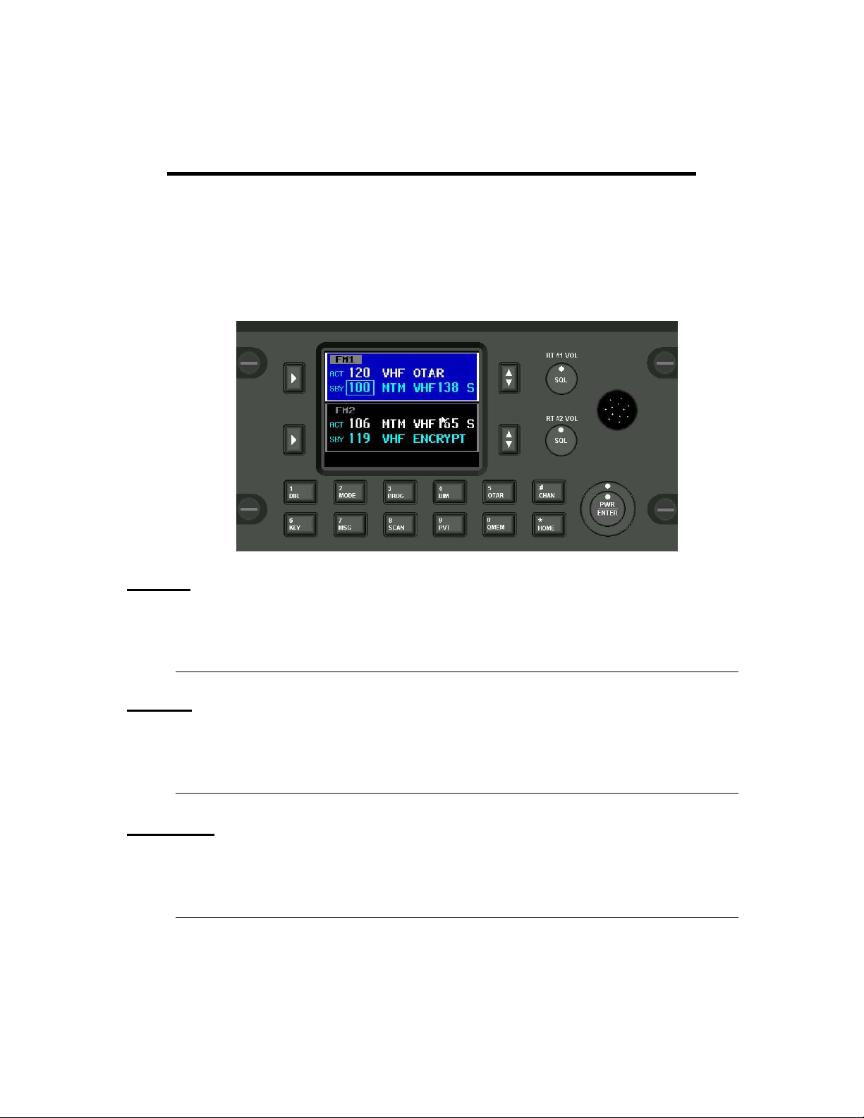
A. P-2000 Panel Mount FM Communications Transceiver
The Wulfsberg P-2000 is a FM Tactical transceiver that incorporates one or two transceiver
modules and control functions into a single panel mount unit. Part number variations of the
unit exist for any combination of the following frequency bands: 138-174 MHz, 403-470 MHz,
450-520 MHz, and 806-870 MHz. Each transceiver module with the exception of the 806-870
MHz band can transmit with 1 or 10 Watts transmit power. The 800 MHz unit produces 1 and
3 watts transmit power. The P-2000 can operate by itself or in conjunction with the C-2000
control display acting as a remote slave control. Input voltage is 28 volts DC and the keypad
is backlit from either 28VDC, 5 VDC or 5 VRMS AC.
The P-2000 transceiver is designed to be mounted in the instrument panel that will fit a
standard DZUS mounting. Two connectors, a DB-25 and DB-15 accept all harness wiring on
the rear of the P-2000, while two TNC type RF connector provides the antenna connection
through conventional coaxial cables. For models containing one transceiver, only one
antenna port is provided.
The P-2000 consists of functional subassemblies interconnected via standard connectors and
ribbon cables. The case of the P-2000 is designed to be disassembled easily to expose most
subassemblies or circuit modules for service. All adjustments to audio levels can be made
via software and do not require the disassembly of the box. Internal test points are exposed
and available to the service technician without having to remove circuit module
subassemblies or use extender cables or cards.
The P-2000 is designed to be drop-in replacement for the C-962A/S Control unit for the
Wulfsberg RT-9600/7200 transceiver systems also known as the ARC-513 with the exception
of the 28 Volt input power. Due to increased 28 power requirements of the P-2000, wire size
Publication No. 150-049106 Page 3 of 41
Rev. A P-2000 Installation Manual
Oct 2003
Page 4

P-2000/C-2000/RT-2000
Installation Manual
on this input may need to be increased to 20 AWG. All other microphone inputs/headset
outputs and backliting are compatible.
B. C-2000 Control Display Unit
The Wulfsberg C-2000 is a control display unit that can be used as a slave control head with
a P-2000 panel mount transceiver, or as a primary or slave control head for the RT- 2000
remote transceiver. Versions of the C-2000 include black faceplate and options for either
Standard or NVG compatible displays. Input voltage is 28 volts DC and the keypad is backlit
from either 28 VDC, 5 VDC or 5 VRMS.
The C-2000 Control Display Unit is designed to be mounted in the instrument panel that will
fit a standard DZUS mounting. Two connectors, a DB-25 and DB-15, accept all harness
wiring on the rear of the P-2000.
Front panel controls establish and display the operating status of all RT-2000 or P-2000
functions when operating as a slave control unit.
C. RT-2000 Remote Mount FM Communications Transceiver
The Wulfsberg RT-2000 is a FM Tactical transceiver that incorporates one or two transceiver
modules and control functions into a single panel mount unit. Part number variations of the
unit exist for any combination of the following frequency bands: 138-174 MHz, 403-470 MHz,
450-520 MHz, and 806-870 MHz. Each transceiver module with the exception of the 806-870
MHz band can transmit with 1 or 10 Watts transmit power. The 800 MHz unit produces 1 and
3 watts transmit power. The RT-2000 is designed to be controlled by a C-2000 control
display. Input voltage is 28 volts DC and the keypad is backlit from either 28VDC, 5 VDC or
5 VRMS AC.
The RT-2000 transceiver is designed to be mounted rack mounted. Two connectors, a DB25 and DB-15 accept all harness wiring on the rear of the RT-2000, while two TNC type RF
connector provides the antenna connection through conventional coaxial cables. For models
containing one transceiver, only one antenna port is provided.
The RT-2000 consists of functional subassemblies interconnected via standard connectors
and ribbon cables. The case of the RT-2000 is designed to be easily disassembled to expose
most subassemblies or circuit modules for service. All adjustments to audio levels can be
made via software and do not require the disassembly of the box. Internal test points are
exposed and available to the service technician without having to remove circuit module
subassemblies or use extender cables or cards.
The RT-2000 is designed to fit into a rack space equivalent with the Wulfsberg RT-9600 with
exception of depth. The RT-2000 is only approximately 7 inches deep vs. the nearly 14 inch
depth of the RT-9600.
Multiple C-2000’s can be used for multi-point control of the RT-2000.
Page 4 of 41 Publication No. 150-049106
P-2000 Installation Manual Rev. A
Oct 2003
Page 5

P-2000/C-2000/RT-2000
INSTALLATION MANUAL
4. Technical Characteristics
A. P-2000 Panel Mount Transceiver
CHARACTERISTICS DESCRIPTION
Certification
FAA In Process (STC Helicopter and Fixed Wing Aircraft)
Software DO-170B Level D
Environmental DO-160D
[(B4/F1)X]BAB[S/U]EXXXXXZZAZZ[J/F]M[XXC3]XXA
FCC FRW-2000-(VHF,UHF-1,UHF-2, 800)
Industry Canada TBD
Emission Designator
156 – 158 MHz Part 80.379, 87.187(l), 16K0F3E
136 – 174 MHz Part 90.210, 16K0F3E, 11K0F3E, 8K10F1E, 8K0F1D
403 – 520 MHz Part 90.210, 16K0F3E, 11K0F3E
806 – 870 MHz Part 90, 16K0F3E, 11K0F3E, 8K10F1E, 8K0F1D
Altitude 51,000 feet ASL (15,545 meters)
Temperature Range
Operation
Storage
-30°C to 60°C (-22°F to +140°F)
-55°C to 85°C (-67°F to +185°F)
Cooling Internal Electric Fan
Weight
P-2000 (Single Transceiver) 3.10 lbs. Max.
P-2000 (Dual Transceiver) 3.70 lbs. Max.
Mounting Dzus
Height 3.0 Inches max.
Width 5.75 inches max.
Depth 6.40 Inches max. (Not Including Connectors)
Input Power Requirements
Normal Voltage Range 22.0 to 30.2 VDC
Abnormal Voltage Range 20.5 to 32.2 VDC
Emergency Operation 18.0 VDC
P-2000 (Single Transceiver)
Receive 0.5 Amp Nominal. .75 Amp Max
Transmit 2.5 Amp Nominal. 3.0 Amp Max.
P-2000 (Dual Transceiver)
Receive 0.5 Amp nominal. 1.0 Amp Max
Transmit 3.0 Amp nominal. 4.0 Amp Max.
P-2000 Panel Lighting 5 VDC, 5 Vrms and 28 VDC (Voltage Sense Only)
Faceplate Colors Black or Grey
Channel Memory 240/255/510 Depending on options
Frequency Band P-2000/RT-2000 Any combination of one or two bands listed below
136-174 MHz, 136-174 MHz (NTIA Compliant)
403-470 MHz, 380-470 MHz
450-520 MHz
Publication No. 150-049106 Page 5 of 41
Rev. A P-2000 Installation Manual
Oct 2003
Page 6

P-2000/C-2000/RT-2000
Installation Manual
806-870 MHz
Channel Spacing 12.5 kHz, 20 kHz, 25 kHz
Receiver Specifications
Modes FM, P-25, P-25 Trunking, Motorola 3600 Baud Trunking
Sensitivity
Analog (12 dB SINAD) Better than .4 uV (-115 dBm)
Digital (5% BER) Better than .4 uV (-115 dBm)
Quieting
Analog (20 dB SINAD) .6 uV (-111.5 dBm)
Digital Not Applicable
Selectivity
Analog (12.5 kHz) -65 dB (NTIA Version: -70 dB)
Analog (25.0 kHz) -70 dB (NTIA Version: -80 dB)
Intermod Rejection
Analog (12.5) -70 dB
Analog (25.0) -70 dB
Spurious Rejection
Analog (12.5 kHz) -65 dB (NTIA Version: -70 dB)
Analog (25.0 kHz) -70 dB (NTIA Version: -85 dB)
Digital (5% BER) -70 dB (NTIA Version: -85 dB)
Unwanted Emissions
Narrow Band -60 dBm
Wide Band -60 dBm
Frequency Stability ± 1.5 PPM
Audio Output
Headset Out 100 mW Maximum into 600 ohms
Normalized Out 1.75 VRMS into 10k Load
External Speaker Out .9 VRMS into 10k Load
Audio Distortion < 2% at Maximum Audio Output
Hum and Noise
Unsquelched <-40 dB
Squelched <-50 dB
Transmitter Specifications
Duty Cycle 25% at Full Power, Continuous at reduced power.
RF Power Output 10 Watt Hi, 1 Watt Lo (3/1 Watt 800 MHz Band Only)
Frequency Stability ± 1.5 PPM
Modulation Limiting:
12.5 kHz Channels ±2.5 kHz
20.0 kHz Channels ±4.0 kHz
25.0 kHz Channels +5.0 kHz
Unwanted Emissions < -70 dBc (-70 dBc Harmonics, -85 dBC Spurious)
Hum and Noise
Narrow Band -42 dB
Wide Band -48 dB
Audio Response
Dual Microphone .25 VMRS into 150 ohm Carbon or Carbon Equivalent
Transmit Distortion < 2%. @ 1 kHz
Sidetone Fidelity 6 dB max variation, 350 Hz to 2500 Hz
Page 6 of 41 Publication No. 150-049106
P-2000 Installation Manual Rev. A
Oct 2003
Page 7

P-2000/C-2000/RT-2000
INSTALLATION MANUAL
Sidetone Output Adjustable 0 to –30 dB below rated output.
Publication No. 150-049106 Page 7 of 41
Rev. A P-2000 Installation Manual
Oct 2003
Page 8

P-2000/C-2000/RT-2000
Installation Manual
B. C-2000 Control Display Unit
CHARACTERISTICS DESCRIPTION
Certification
FAA In Process (PMA/STC Helicopter and Fixed Wing Aircraft)
Software DO-170B Level D
Environmental DO-160D
[(B4/F1)X]BAB[S/U]EXXXXXZZAZZ[J/F]M[XXC3]XXA
FCC Part 15
Industry Canada Pending
Altitude 51,000 feet ASL (15,545 meters)
Temperature Range
Operation
Storage
-30°C to 60°C (-22°F to +140°F)
-55°C to 85°C (-67°F to +185°F)
Cooling Internal Electric Fan
Weight 2.00 lbs. Max.
Mounting Dzus
Overall Dimensions
Height 3.0 Inches max.
Width 5.75 inches max.
Depth 6.40 inches max. (without Connectors)
Input Power Requirements
Normal Voltage Range 22.0 to 30.2 VDC
Abnormal Voltage Range 20.5 to 32.2 VDC
Emergency Operation 18.0 VDC
Input Current 0.5 Amp nominal. 1.0 Amp Max
Panel Lighting 5 VDC, 5 Vrms and 28 VDC (Voltage Sense Only)
Faceplate Colors Black or Grey
Display Options LCD Color or LCD Color with NVG compatibility
Channel Memory 240/255/510 Depending on options
Data Bus CAN Serial with Wulfsberg Proprietary Protocol
C. RT-2000 Remote Mount Transceiver
CHARACTERISTICS DESCRIPTION
Certification
FAA In Process (PMA/STC Helicopter and Fixed Wing Aircraft)
Software DO-170B Level D
Environmental DO-160D
[(B4/F1)X]BAB[S/U]EXXXXXZZAZZ[J/F]M[XXC3]XXA
FCC Pending FRW-2000-(VHF,UHF-1,UHF-2, 800)
Industry Canada Pending
Emission Designator
156 – 158 MHz Part 80.379, 87.187(l), 16K0F3E
136 – 174 MHz Part 90.210, 16K0F3E, 11K0F3E, 8K10F1E, 8K0F1D
403 – 520 MHz Part 90.210, 16K0F3E, 11K0F3E
806 – 870 MHz Part 90, 16K0F3E, 11K0F3E, 8K10F1E, 8K0F1D
Altitude 51,000 feet ASL (15,545 meters)
Page 8 of 41 Publication No. 150-049106
P-2000 Installation Manual Rev. A
Oct 2003
Page 9

P-2000/C-2000/RT-2000
INSTALLATION MANUAL
Temperature Range
Operation
Storage
-30°C to 60°C (-22°F to +140°F)
-55°C to 85°C (-67°F to +185°F)
Cooling Free air circulation
Weight
RT-2000 (Single Transceiver) 2.50 lbs. Max.
RT-2000 (Dual Transceiver) 3.50 lbs. Max.
Mounting Mounting Tray
Overall Dimensions
Height 3.0 inches max.
Width 5.75 inches max.
Length 7.49 inches max (without Connectors)
Input Power Requirements
Normal Voltage Range 22.0 to 30.2 VDC
Abnormal Voltage Range 20.5 to 32.2 VDC
Emergency Operation 18.0 VDC
RT-2000 (Single Transceiver)
Receive 0.5 Amp nominal. .75 Amp Max
Transmit 2.5 Amp nominal. 3.0 Amp Max.
RT-2000 (Dual Transceiver)
Receive 0.5 Amp nominal. .75 Amp Max
Transmit 3.0 Amp nominal. 4.0 Amp Max.
Frequency Band P-2000/RT-2000 Any combination of one or bands listed below
136-174 MHz, 136-174 MHz (NTIA Compliant)
403-470 MHz, 380-470 MHz
450-520 MHz
806-870 MHz
Data Bus CAN Serial with Wulfsberg Proprietary Protocol
Encryption Options DES/DES-XL/DES-OFB/AES/DVP/DVI
OTAR Options MDC1200 OTAR, P25 OTAR
Trunking Options Smartzone, P25
Receiver Specifications
Modes FM, P-25, P-25 Trunking, Motorola 3600 Baud Trunking
Sensitivity
Analog (12 dB SINAD) Better than .4 uV (-115 dBm)
Digital (5% BER) Better than .4 uV (-115 dBm)
Quieting
Analog (20 dB SINAD) .6 uV (-111.5 dBm)
Digital Not Applicable
Selectivity
Analog (12.5 kHz) -65 dB (NTIA Version: -70 dB)
Analog (25.0 kHz) -70 dB (NTIA Version: -80 dB)
Intermod Rejection
Analog (12.5) -70 dB
Analog (25.0) -70 dB
Publication No. 150-049106 Page 9 of 41
Rev. A P-2000 Installation Manual
Oct 2003
Page 10

P-2000/C-2000/RT-2000
Installation Manual
Spurious Rejection
Analog (12.5 kHz) -65 dB (NTIA Version: -70 dB)
Analog (25.0 kHz) -70 dB (NTIA Version: -85 dB)
Digital (5% BER) -70 dB (NTIA Version: -85 dB)
Unwanted Emissions
Narrow Band -60 dBm
Wide Band -60 dBm
Frequency Stability ± 1.5 PPM
Audio Output
Headset Out 100 mW Maximum into 600 ohms
Normalized Out 1.75 VRMS into 10k Load
External Speaker Out .9 VRMS into 10k Load
Audio Distortion < 2% at Maximum Audio Output
Hum and Noise
Unsquelched <-40 dB
Squelched <-50 dB
Transmitter Specifications
Duty Cycle 25% at Full Power, Continuous at reduced power.
RF Power Output 10 Watt Hi, 1 Watt Lo (3/1 Watt 800 MHz Band Only)
Frequency Stability ± 1.5 PPM
Modulation Limiting:
12.5 kHz Channels ±2.5 kHz
20.0 kHz Channels ±4.0 kHz
25.0 kHz Channels +5.0 kHz
Unwanted Emissions < -70 dBc (-70 dBc Harmonics, -85 dBC Spurious)
Hum and Noise
Narrow Band -42 dB
Wide Band -48 dB
Audio Response
Dual Microphone .25 VMRS into 150 ohm Carbon or Carbon Equivalent
Transmit Distortion < 2%. @ 1 kHz
Sidetone Fidelity 6 dB max variation, 350 Hz to 2500 Hz
Sidetone Output Adjustable 0 to –30 dB below rated output.
Page 10 of 41 Publication No. 150-049106
P-2000 Installation Manual Rev. A
Oct 2003
Page 11

P-2000/C-2000/RT-2000
INSTALLATION MANUAL
5. Available Configuration Variations
A. P-2000 Part Number Matrix
400-049200-AB-CDE-WWWW-XXXX
A: Major Hardware Version
1 = Initial Release
B: Major Software Version
1 = Initial Release
C: Reserved for future use (Always marked "0")
D: Faceplate Option
1 = Black Face Plate
2 = Grey Face Plate
E: Display Option
1 = Standard Display
2 = NVG Compatible Display
WWWW: ITM #1 Options
W W W W
| | | |-------------------------------------------------------------Encryption
| | |--Trunking 0 = none
| | 1 = None 1 = DES(XL)/DES-OFB
| | 2 = Motorola Smartnet(3600 Baud) 2 = DVP-XL
| | 3 = Motorola SmartZone(3600 Baud) 3 = DVI-XL
| | 4 = P25 4 = AES
| | 5 = P25 and Motorola SmartZone
| |----Frequency Band
| 1 = 136 - 174 MHz
| 2 = 403 - 470 MHz
| 3 = 450 - 520 MHz
| 4 = 806 - 870 MHz
| 5 = 136 - 174 MHz (NTIA Compliant)
| 6 = 380 - 470 MHz
|-----Reserved (Always marked "0")
XXXX: ITM #2 Options
X X X X
| | | |-------------------------------------------------------------Encryption
| | |--Trunking 0 = none
| | 1 = None 1 = DES(XL)/DES-OFB
| | 2 = Motorola Smartnet(3600 Baud) 2 = DVP-XL
| | 3 = Motorola SmartZone(3600 Baud) 3 = DVI-XL
| | 4 = P25 4 = AES
| |----Frequency Band
| 0 = None
| 1 = 136 - 174 MHz
| 2 = 403 - 470 MHz
| 3 = 450 - 520 MHz
| 4 = 806 - 870 MHz
| 5 = 136 - 174 MHz (NTIA Compliant)
Publication No. 150-049106 Page 11 of 41
Rev. A P-2000 Installation Manual
Oct 2003
Page 12

P-2000/C-2000/RT-2000
Installation Manual
| 6 = 380 - 470 MHz
|-----Reserved (Always marked "0")
B. C-2000 Part Number Matrix
400-049300-AB-CDE
A: Major Hardware Version
1 = Initial Release
B: Major Software Version
1 = Initial Release
C: Reserved for future use (Always marked "0")
D: Faceplate Option
1 = Black Face Plate
2 = Grey Face Plate
E: Display Option
1 = Standard Display
2 = NVG Compatible Display
Page 12 of 41 Publication No. 150-049106
P-2000 Installation Manual Rev. A
Oct 2003
Page 13

P-2000/C-2000/RT-2000
INSTALLATION MANUAL
C. RT-2000 Part Number Matrix
400-049400-AB-CDE-WWWW-XXXX
A: Major Hardware Version
1 = Initial Release
B: Major Software Version
1 = Initial Release
C: Reserved for future use (Always marked "0")
D: Reserved for future use (Always marked “0”)
E: Reserved for future use (Always marked “0”_
WWWW: ITM #1 Options
W W W W
| | | |-------------------------------------------------------------Encryption
| | |--Trunking 0 = none
| | 1 = None 1 = DES(XL)/DES-OFB
| | 2 = Motorola Smartnet(3600 Baud) 2 = DVP-XL
| | 3 = Motorola SmartZone(3600 Baud) 3 = DVI-XL
| | 4 = P25 4 = AES
| | 5 = P25 and Motorola SmartZone
| |----Frequency Band
| 1 = 136 - 174 MHz
| 2 = 403 - 470 MHz
| 3 = 450 - 520 MHz
| 4 = 806 - 870 MHz
| 5 = 136 - 174 MHz (NTIA Compliant)
| 6 = 380 - 470 MHz
|-----Reserved (Always marked "0")
XXXX: ITM #2 Options
X X X X
| | | |-------------------------------------------------------------Encryption
| | |--Trunking 0 = none
| | 1 = None 1 = DES(XL)/DES-OFB
| | 2 = Motorola Smartnet(3600 Baud) 2 = DVP-XL
| | 3 = Motorola SmartZone(3600 Baud) 3 = DVI-XL
| | 4 = P25 4 = AES
| |----Frequency Band
| 0 = None
| 1 = 136 - 174 MHz
| 2 = 403 - 470 MHz
| 3 = 450 - 520 MHz
| 4 = 806 - 870 MHz
| 5 = 136 - 174 MHz (NTIA Compliant)
| 6 = 380 - 470 MHz
|-----Reserved (Always marked "0")
Publication No. 150-049106 Page 13 of 41
Rev. A P-2000 Installation Manual
Oct 2003
Page 14

P-2000/C-2000/RT-2000
Installation Manual
D. Antenna Options
The following antennas are required for use with the P-2000/RT-2000 Transceivers.
Antenna Name Wulfsberg Part
Frequency Band FAA Certification
Number
AT-695 121-0019-000 136-174 MHz TSO
AT-462 121-014378-01 380-520 MHz PMA
AT-806 121-019079-01 806-870 TSO
See Figure 2-1, 2-2,2-3 for envelope drawings of antennas.
E. RT-2000 Mounting Tray (Wulfsberg P/N 300-XXXXXX-01)
See Figure 2 –4 for envelope drawing of RT-2000 Mounting Tray.
F. Required Accessories
Part Type Part Description Wulfsberg Part Number
Connector DB-25 Connector 030-02703-0000
Connector component DB-25 Backshell 129-214803-25
Connector component DB-25 Slide Locks 129-141470-25
Connector DB-15 Connector 129-217927-01
Connector component DB-15 Backshell 129-241803-15
Connector component DB-15 Slide Locks 129-141470-15
RF Connector Straight TNC for RG-193 Coax Cable 129-041810-01
RF Connector Right angleTNC for RG-193 Coax Cable 129-041811-01
Cable RT-2000 KVL Data Cable 300-349082-01
Software XTS-3000 PC Programming Software ***Available from Motorola
Software XTS-5000 PC Programming Software ***Available from Motorola
***XTS-3000 PC Programming Software (RVN4184) is required for transceiver options 1
through 4. Options 5 and 6 require XTS-5000 PC Programming Software(RVN4186). These
Motorola part numbers are subject to change without notice.
Motorola Software must be obtained by the operator directly from Motorola Customer Service
Department via the following telephone numbers:
U.S. and Canadian Customers 1-800-422-4210
Federal Government Customers 1-800-826-1931
Outside U.S. Customer 1-847-538-8023
Page 14 of 41 Publication No. 150-049106
P-2000 Installation Manual Rev. A
Oct 2003
Page 15

P-2000/C-2000/RT-2000
INSTALLATION MANUAL
SECTION 2 – INSTALLATION
1. General
This section contains suggestions and factors to consider before installing the P-2000/C2000/RT-2000. Close adherence to these suggestions will assure a more satisfactory
performance from the equipment.
2. Unpacking and Inspecting Equipment
Exercise extreme care when unpacking the equipment. Make a visual inspection of the units for
evidence of damage incurred during shipment. If a claim for damage is to be made, save the
shipping container to substantiate the claim. The claim should be promptly filed with the
transportation company. It would be advisable to retain the container and packaging material after
all equipment has been removed in the event that equipment storage or reshipment should
become necessary.
3. Equipment Installation
The P-2000/C-2000/RT-2000 installations will conform to standards designated by the customer,
installing agency, and existing conditions as to the unit location and type of installation. See
Figures 2-1 through 2-7 for an outline drawings of the LRU’s, installation tray, and antennas.
Before beginning installation the installing agency should review the drawings, electrical
interwiring diagram and installation pictorials which are located in this section, and establish
requirements to a particular aircraft.
A. Cooling Considerations
The greatest single contributor to increased reliability of all modern day avionics is limiting the
maximum operating temperature of the individual units, whether panel-mounted or remote-
mounted. While modern day circuit designs consume far less electrical energy, the watts per
cubic inch dissipated within the avionics units still remains much the same due to high density
packaging techniques utilized. Consequently, the importance of providing avionics cooling is
essential to the life span of the unit.
The combined heat load of several units operating in a typical avionics location will
significantly degrade the reliability of the avionics if provisions for cooling are not incorporated
in the initial installation. Failure to provide cooling will certainly lead to increased avionics
maintenance costs and may void the Wulfsberg warranty.
B. P-2000 Mechanical Installation
(1) Select the P-2000 mounting location. Insure that unit will be easily accessible and
clearly visible to the operator. The location should be free from excessive moisture,
vibration, heat and noise generating sources. The unit has standard Dzus mount
dimensions as shown in Figure 2-1. Allow adequate space and service loops for
installation of cables and connectors.
Publication No. 150-049106 Page 15 of 41
Rev. A P-2000 Installation Manual
Oct 2003
Page 16

P-2000/C-2000/RT-2000
Installation Manual
(2) The installing agency will supply and fabricate all external cables. The connectors
are supplied separately and are listed in Section 1.F.
(3) The length and routing of the external cables must be carefrully studied and planned
before attempting actual installation. Avoid sharp bends and placing cables too
near other aircraft cables.
(4) Use only recommended wire sizes and wire type for interwiring. Wire sizes and wire
type are listed on the interwiring diagrams.
C. C-2000 Mechanical Installation
(1) Select the P-2000 mounting location. Insure that unit will be easily accessible and
clearly visible to the operator. The location should be free from excessive moisture,
vibration, heat and noise generating sources. The unit has standard Dzus mount
dimensions as shown in Figure 2-1. Allow adequate space and service loops for
installation of cables and connectors.
(2) The installing agency will supply and fabricate all external cables. The connectors
are supplied separately and are listed in Section 1.F.
(3) The length and routing of the external cables must be carefrully studied and planned
before attempting actual installation. Avoid sharp bends and placing cables too
near other aircraft cables.
(4) Use only recommended wire sizes and wire type for interwiring. Wire sizes and wire
type are listed on the interwiring diagrams.
D. RT-2000 Mechanical Installation
(1) Select the RT-2000 mounting location. The location should be free from excessive
moisture, vibration, heat and noise generating sources. The unit can be rigidly
mounted. Allow at least one inch of free air space around the top and rear of the unit
and one-half inch along each side. Allow adequate space for installation of cables
and connectors.
(2) Refer to Figure 2-3 for the RT-2000 mounting dimensions.
(3) Mark, punch, and drill the mounting holes. Care must be taken to avoid damage to
adjacent equipment or cables.
(4) Secure the mounting tray firmly in place.
(5) Secure the RT-2000 to the mounting tray and connect all appropriate connectors
taking care to apply the correct RF connector to the desired transceiver.
Page 16 of 41 Publication No. 150-049106
P-2000 Installation Manual Rev. A
Oct 2003
Page 17

P-2000/C-2000/RT-2000
INSTALLATION MANUAL
E. Antenna Mechanical Installation
(1) Antenna installation is critical to the range and quality of the transmitted signal.
Care should be taken to keep all antennas a separated as possible. A minimum of
70 cm should be observed if possible.
(2) Whenever possible, mount antennas on the bottom of the aircraft. The only
exception is if two antennas covering the same frequency band are used, put one
on the top of the aircraft and the other on the bottom to achieve maximum isolation.
If this is not possible, put on the front of the aircraft and one on the rear.
(3) The antennas should be mounted on a flat metal surface to obtain a proper ground
plane. Ensure the antenna is adequately grounded to the aircraft skin (<5 mohm is
a standard rule of thumb).
(4) P-2000/RT-2000 antennas should be mounted a minimum of 20 cm from each
other.
(5) Wulfsberg recommends the use of RG-193 on most installations. Installers can
substitute other types of coax than RG-193 to get better performance especially at
higher frequencies. Be aware that each type of coaxial cable requires specific
connectors that may only be available from the coaxial cable manufacturer.
Publication No. 150-049106 Page 17 of 41
Rev. A P-2000 Installation Manual
Oct 2003
Page 18

P-2000/C-2000/RT-2000
Installation Manual
This page intentionally left blank.
Page 18 of 41 Publication No. 150-049106
P-2000 Installation Manual Rev. A
Oct 2003
Page 19

P-2000/C-2000/RT-2000
INSTALLATION MANUAL
Remove this page and insert 154-049200 (P-2000 outline), Sheet 1 of 1 (Fig. 2-1).
Publication No. 150-049106 Page 19 of 41
Rev. A P-2000 Installation Manual
Oct 2003
Page 20

P-2000/C-2000/RT-2000
Installation Manual
Remove this page and insert 154-049300 (C-2000 Outline), Sheet 1 of 1 (Fig. 2-2).
Page 20 of 41 Publication No. 150-049106
P-2000 Installation Manual Rev. A
Oct 2003
Page 21

P-2000/C-2000/RT-2000
INSTALLATION MANUAL
Remove this page and insert 154-049400 (RT-2000 Outline), Sheet 1 of 1 (Fig. 2-3).
Publication No. 150-049106 Page 21 of 41
Rev. A P-2000 Installation Manual
Oct 2003
Page 22

P-2000/C-2000/RT-2000
Installation Manual
Remove this page and insert 154-049065 (RT-2000 Mounting Tray), Sheet 1 of 1 (Fig. 2-5).
.
Page 22 of 41 Publication No. 150-049106
P-2000 Installation Manual Rev. A
Oct 2003
Page 23

P-2000/C-2000/RT-2000
INSTALLATION MANUAL
Remove this page and insert 121-0019-000 (AT-695 Outline), Sheet 1 of 1 (Fig. 2-6).
Publication No. 150-049106 Page 23 of 41
Rev. A P-2000 Installation Manual
Oct 2003
Page 24

P-2000/C-2000/RT-2000
Installation Manual
Remove this page and insert 121-014378 (AT-462), Sheet 1 of 1 (Fig. 2-7).
Page 24 of 41 Publication No. 150-049106
P-2000 Installation Manual Rev. A
Oct 2003
Page 25

P-2000/C-2000/RT-2000
INSTALLATION MANUAL
Remove this page and insert 121-049079 (AT-806), Sheet 1 of 1 (Fig. 2-8).
Publication No. 150-049106 Page 25 of 41
Rev. A P-2000 Installation Manual
Oct 2003
Page 26

P-2000/C-2000/RT-2000
Installation Manual
Section 3 - Electrical Installation
1. General Information
The Flexcomm “2000” family of products provide for many installation options. Normally the
requirements can be determined by answering the following questions.
(1) Does the user want a transceiver that is remote mounted or panel mounted?
This determines whether a P-2000 (panel mount) or a RT-2000 (Remote mount)
transceiver will be used.
If a RT-2000 remote mount transceiver is used, then at least one C-2000 control
head must also be specified. Additional C-2000's can be added for control of the
RT-2000 from remote locations.
If a P-2000 panel mount transceiver is desired then additional C-2000's can be
added for control of the P-2000 from remote locations.
(2) How many channels must be monitored at a time - one or two?
This determines how many Internal Transceiver Modules (ITM’s) are inside the P2000 or the RT-2000. The P-2000 and RT-2000 can have one or two ITM's.
If the transceiver has two ITM's, then the user has the choice of using one or two
mic/headset ports. Usually this is determined by the number of audio panel ports
available for FM tactical radios.
In new installations it is recommended that two audio ports be used so that each
ITM can be accessed independently by two operators. For retrofit installations, one
port can be used to access both ITM's.
If only one microphone/headset port is available, then connect it to FM 1
mic/headset port on the transceiver. The user will then need to select using the P2000 or C-2000 front panel controls which ITM to use for transmit. The receive
audio from both ITM's will be summed together and output on FM 1 Headset Port.
If two positions on the audio panel are available, then connect the 1
st
position to FM
1 mic/headset and position #2 to FM 2 mic/headset. This will allow for two users to
independently operate the two ITM's.
(3) Does the audio panel have individual RX audio volume controls?
If yes, then the P-2000 or C-2000 can have the volume controls programmed by the
installer to a set level that the user will not be able to change via the volume knobs
on the front of the P-2000/C-2000. In this case, the user will go to the audio panel
to change the volume - not the P-2000 or C-2000.
Page 26 of 41 Publication No. 150-049106
P-2000 Installation Manual Rev. A
Oct 2003
Page 27

P-2000/C-2000/RT-2000
INSTALLATION MANUAL
2. Sample System Block Diagrams
The following block diagrams are intended to show various installation configurations of the
“2000” family of products. Due to the flexibility of the system components it is impossible to
create wiring diagrams for all configurations. However, with the examples given by the
manufacturer and the technical descriptions of connector pins, a competent designer should be
able to create wiring diagrams for their specific application.
Figure 3.1 shows diagrams that use a single P-2000 and Single C-2000/RT-2000. They attempt
to show how single and multiple Mic/Headset interfaces can be used.
Figure 3.2 shows diagrams that use a combination of C-2000 control units and P-2000/RT-2000
transceivers with audio panels without volume controls.
Figure 3.3 shows diagrams that employ a combination of C-2000 control units and P-2000/RT2000 transceivers.
Publication No. 150-049106 Page 27 of 41
Rev. A P-2000 Installation Manual
Oct 2003
Page 28

P-2000/C-2000/RT-2000
Installation Manual
Remove this page and Insert P-2000 Block diagrams Page 1 here. Fig 3.1
Page 28 of 41 Publication No. 150-049106
P-2000 Installation Manual Rev. A
Oct 2003
Page 29

P-2000/C-2000/RT-2000
INSTALLATION MANUAL
Remove this page and Insert P-2000 Block diagrams Page 1 here. Fig 3.2
Publication No. 150-049106 Page 29 of 41
Rev. A P-2000 Installation Manual
Oct 2003
Page 30

P-2000/C-2000/RT-2000
Installation Manual
Remove this page and Insert P-2000 Block diagrams Page 1 here. Fig 3.3
Page 30 of 41 Publication No. 150-049106
P-2000 Installation Manual Rev. A
Oct 2003
Page 31
P-2000/C-2000/RT-2000
INSTALLATION MANUAL
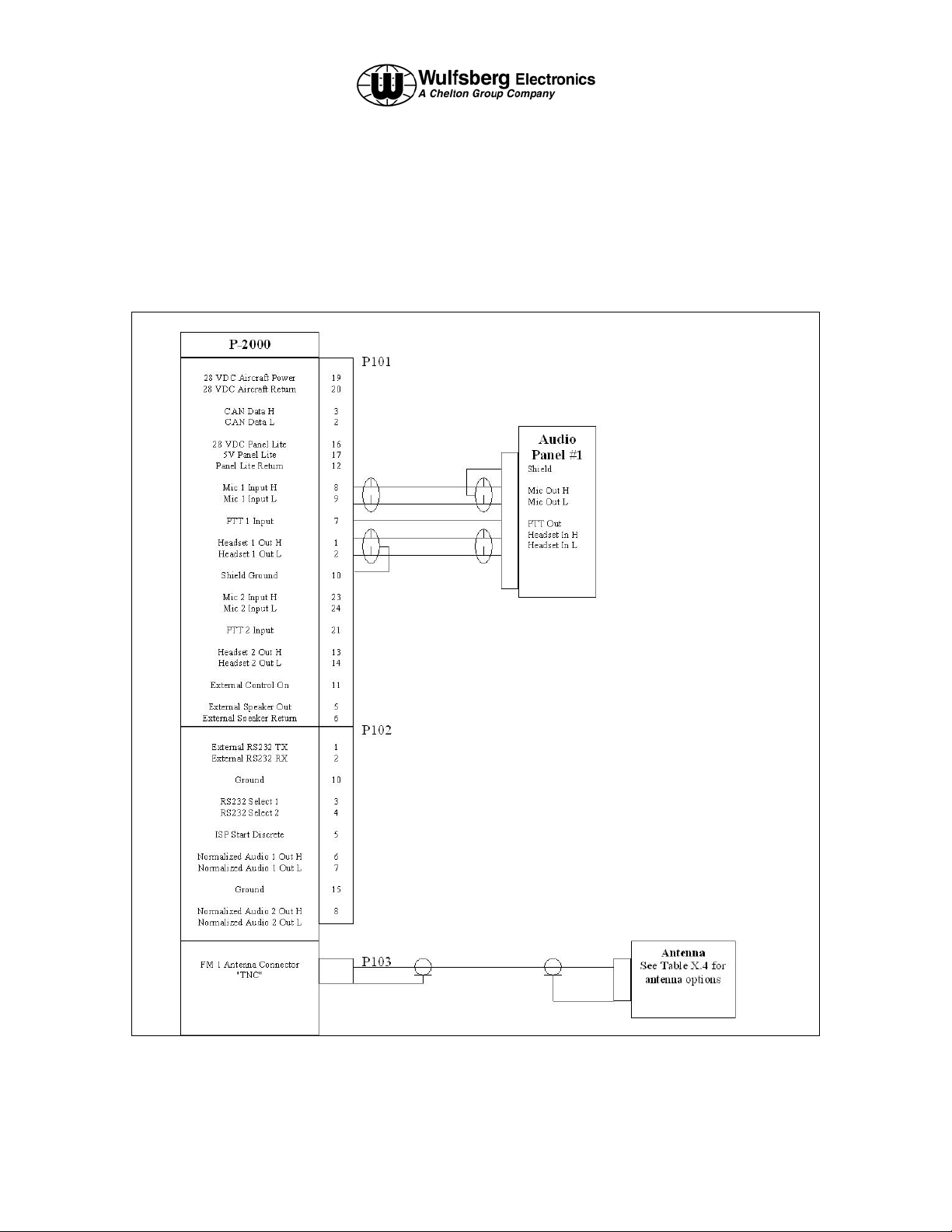
3. Sample Interconnect Wiring Diagram
The following wiring diagram is intended to show a basic installation of the Flexcomm “2000”
family of products. Due to the flexibility of the system components it is impossible to create wiring
diagrams for all configurations. However, with the examples given by the manufacturer and the
technical descriptions of connector pins, a competent designer should be able to create wiring
diagrams for their specific application.
Publication No. 150-049106 Page 31 of 41
Rev. A P-2000 Installation Manual
Oct 2003
Page 32

P-2000/C-2000/RT-2000
Installation Manual
4. Connector Pin Number and Descriptions
The following tables and pin descriptions are for the P-2000/C-2000/RT-2000 J101(DB-15) and
J102 (DB-15) connectors.
J101 Pin Numbers and Signal Names
Pin SIGNAL NAME
1 Headset 1 Out H
2 Headset 1 Out L
3 CAN Data H
4 CAN Data L
5 External Speaker Out
6 External Speaker Return
7 PTT 1 Input
8 Mic 1 Input H
9 Mic 1 Input L
10 Shield Ground
11 External On/OFF Control
12 Panel Lite Return
13 Headset 2 Out H
14 Headset 2 Out L
15 Reserved Spare #1
16 28 VDC Panel Lite
17 5 V Panel Lite
18 Reserved Spare #2
19 28 VDC Aircraft Power
20 28 VDC Aircraft Return
21 PTT 2 Input
22 Reserved Spare #3
23 Mic 2 Input H
24 Mic 2 Input L
25 Reserved Spare #4
Table 3.1 J101 Pin Numbers and Signal Names
Page 32 of 41 Publication No. 150-049106
P-2000 Installation Manual Rev. A
Oct 2003
Page 33

P-2000/C-2000/RT-2000
INSTALLATION MANUAL
Pin - Signal Name (J101 25 Pin D-sub)
1 - Headset 1 Out H
This analog output provides the High side of the receive and sidetone audio output from
either FM-1 transceiver (Mode 2) or the summation of FM-1 and FM-2 (Mode 1).
Standard audio levels of 100 mW into 600 ohm load is provided for standard modulation
(1.0 kHz tone, 3 kHz FM Mod). This output is normally sent an audio panel. This output
must use shielded wire.
2 - Headset 1 Out L
This analog output provides the Low side of the receive and sidetone audio output from a
transceiver. Normally this output is either grounded or sent to an audio panel. This
output must use shielded wire.
3 - CAN Data H
This bi-directional pin provides for data communications between a C-2000 and P-2000
or RT-2000. Voltage levels range between 0 and 5 VDC. This pin is only used when a
system incorporates a C-2000. Twisted Shielded wire should be used with this pin.
4 - CAN Data L
This bi-directional pin provides for data communications between a C-2000 and P-2000
or RT-2000. Voltage levels range between 0 and 5 VDC. This pin is only used when a
system incorporates a C-2000. Twisted Shielded wire should be used with this pin.
5 - External Speaker Out
This analog audio output is the summation of the receive audio of either or both
transceiver modules. It does not output sidetone. Normally this audio is provided for
special applications where a speaker rather than Headset is used. It can drive a 10K
load with .9 VRMS. This output is intended to drive a powered speaker. Use shielded
wire.
6 - External Speaker Return
This pin provides the ground path for the external speaker output. Use shielded wire.
7 - PTT 1 Input
This input when grounded activates the transmitter for FM - 1 or FM - 2 (Depending on
operating mode and selected transceiver). Normally this is connected to the audio panel
PTT output. If a discreet microphone is being used (no audio panel) this pin should be
tied to Mic 1 Input L.
Publication No. 150-049106 Page 33 of 41
Rev. A P-2000 Installation Manual
Oct 2003
Page 34

8 - Mic 1 Input H
This pin is the high side of a differential microphone 1 input and provides a 150 ohm input
impedance for the crew microphone input. Normally this pin is connected to the audio
panel. Carbon microphone DC bias is provided by the unit. Standard input of 1kHz tone
@ .25VRMS should produce standard FM modulation out (3.0 kHz). Use shielded wire.
9 - Mic 1 Input L
This pin is the low side of a differential microphone 1 input. Normally this pin is
connected to the audio panel. Use shielded wire.
10 - Shield Ground
All shields of signals originating at the P-2000 or RT-2000 and terminating at other
equipment should be connected to this pin and left un-terminated at the other equipment.
11 - External ON Control
This pin is only used in a system that contains a C-2000. When this pin is grounded the
unit will turn on.
P-2000/C-2000/RT-2000
Installation Manual
12 - Panel Lite Return
The pin provides the ground path for the lite buss input.
13 - Headset 2 Out H
This analog output provides the High side of the receive and sidetone audio output from
FM-2 transceiver (Mode 2). Standard audio levels of 100 mW into 600 ohm load is
provided for standard modulation (1.0 kHz tone, 3 kHz FM Mod). This output is normally
sent an audio panel. This output must use shielded wire.
14 - Headset 2 Out L
This analog output provides the low side of the receive and sidetone audio output from a
transceiver. Normally this output is either grounded or sent to an audio panel. This
output must use shielded wire.
15 - Reserved Spare #1
This reserved for future use.
16 - 28 VDC Panel Lite
This pin provides for 28 VDC aircraft lite dimmer buss control of the keyboard lighting (the
LCD brightness is set by the user via keypad input). This pin does not draw power from
the buss but simply monitors the voltage for proper lite tracking. Either 28 V or 5 volt (pin
17) may be used but not at the same time. This function is not used on the RT-2000 so
no connection is required.
Page 34 of 41 Publication No. 150-049106
P-2000 Installation Manual Rev. A
Oct 2003
Page 35

17 - 5 VDC/5 VRMS Panel lite
This pin provides for 5 VDC or 5 VRMS aircraft lite dimmer buss control of the keyboard
lighting (the LCD brightness is set by the user via keypad input). This pin does not draw
power from the buss but simply monitors the voltage for proper lite tracking. Either 28 V
or 5 volt may be used but not at the same time. This function is not used on the RT2000 so no connection is required.
18 - Reserved Spare #2
This reserved for future use.
19 - 28 VDC Aircraft Power
This pin provides 28 VDC aircraft power to the unit. Loading requirements and proper
circuit breaker choices are P-2000: 4 amps, RT-2000: 4 amps, C-2000: 2 amps.
20 - 28 VDC Aircraft Ground
This pin provides the ground return for the 28 VDC aircraft power to the unit.
P-2000/C-2000/RT-2000
INSTALLATION MANUAL
21 - PTT 2 Input
This input when grounded activates the transmitter for FM - 2. Normally this is connected
to the audio panel PTT output. If a discreet microphone is being used (no audio panel)
this pin should be tied to Mic 2 Input L.
22 - Reserved Spare #3
This reserved for future use.
23 - Mic 2 Input H
This pin is the high side of a differential microphone 2 input and provides a 150 ohm input
impedance for the crew microphone input. Normally this pin is connected to the audio
panel. Carbon microphone DC bias is provided by the unit. Standard input of 1kHz tone
@ .25VRMS should produce standard FM modulation out (3.0 kHz). Use shielded wire.
24 - Mic 2 Input L
This pin is the low side of a differential microphone 2 input. Normally this pin is
connected to the audio panel. Use shielded wire.
25 - Reserved Spare #4
This reserved for future use.
Publication No. 150-049106 Page 35 of 41
Rev. A P-2000 Installation Manual
Oct 2003
Page 36

P-2000/C-2000/RT-2000
Installation Manual
J102 15 Pin D-Sub
Pin SIGNAL NAME
1 External RS232 TX
2 External RS232 RX
3 RS232 Select 1
4 RS232 Select 2
5 ISP Start Discrete
6 Normalized Audio 1 Out H
7 Reserved Spare #5
8 Normalized Audio 2 Out H
9 Reserved Spare #6
10 Ground
11 Reserved Spare #1
12 Reserved Spare #2
13 Reserved Spare #3
14 Reserved Spare #4
15 Ground
Table 3.2 J102 Pin Numbers and Signal Names
Pin - Signal Name
1 - External RS232TX
This pin is a digital output from the unit. It provides for data communication during software flash
procedures.
2 - External RS232RX
This pin is a digital input to the unit. It provides for data communication during software flash
procedures.
3 - RS232 Select 1
4 - RS232 Select 2
This pins select which internal module receive the RS232 data being transferred on pins 1 and 2
of J102. The choices for these pins are listed in the table below:
Pin 3 Pin 4 Selection
N/C N/C TBD
Ground N/C TBD
N/C Ground TBD
Ground Ground TBD
5 - ISP Start Discrete
This pin is used only during Flash software loading during maintenance.
Page 36 of 41 Publication No. 150-049106
P-2000 Installation Manual Rev. A
Oct 2003
Page 37

P-2000/C-2000/RT-2000
INSTALLATION MANUAL
6 - Normalized Audio 1 Out H
This audio pin outputs audio from FM -1 at a constant level - i.e. it is not controlled by the volume
control. This output will produce 1.75VRMS into a 10K load.
7 – Reserved Spare #5
Reserved for future use.
8 – Normalized Audio 2 Out H
This audio pin outputs audio from FM -2 at a constant level - i.e. it is not controlled by the volume
control. This output will produce 1.75VRMS into a 10K load.
9 – Reserved Spare #6
Reserved for future use.
10 - Ground
Ground.
11 - Reserved Spare #1
Reserved for future use.
12 - Reserved Spare #2
Reserved for future use.
13 - Reserved Spare #3
Reserved for future use.
14 - Reserved Spare #4
Reserved for future use.
15 - Ground
Ground.
Publication No. 150-049106 Page 37 of 41
Rev. A P-2000 Installation Manual
Oct 2003
Page 38

P-2000/C-2000/RT-2000
Installation Manual
SECTION 4 – Installation Checkout Procedure
1. Introduction
This procedure should be followed to verify installation of the system.
Procedure
(1) Install all LRU’s and antenna systems.
(2) Verify grounding on antennas is <5 mohms.
(3) Verify grounding between LRU’s and airframe is <.5mohms.
(4) Enable power bus.
(5) Verify display units turn on and initialize. Perform “LEARN” mode if unit requests
it.
(6) Configure the unit for DUAL or SINGLE mice mode. See section 6 for more
information.
(7) Configure the unit for LOCK VOLUME setting.
(8) Press the volume knob for FM1. Verify the discreet RX indicator for FM1 is
displayed and that noise is heard in the headset. Vary FM1 volume knob (if
LOCK VOLUME is set to NO) or the volume knob on the audio or both to very
volume level can be controlled. Perform this test for both FM1 and FM2.
(9) Connect communication analyzer directly into FM1 antenna port (J103). Inject a
signal into the transceiver and verify the reception at .6 uV unsquelches the
audio and the signal is heard in the headset.
(10) Transmit with FM1 and verify power levels, Frequency, and deviation level
(maximum of 5 kHz, normal voice level, 3.0 kHz).
(11) Perform steps 9 and 10 with FM2 if applicable.
(12) Using a “Bird” type watt meter, verify antenna VSWR is less than 2.5 to 1 for all
antennas in the system.
(13) Connect antennas and verify over the air transmissions using the
communications analyzer as the other unit.
(14) Transmit using each transceiver and verify no interference with other systems on
the aircraft such as GPS, AM comms and NAV receivers.
Page 38 of 41 Publication No. 150-049106
P-2000 Installation Manual Rev. A
Oct 2003
Page 39

Introduction
This document contains instructions for testing a FLEXCOMM 200 system on a periodic
maintenance cycle to assure continuous airworthiness. This document is intended to
supplement the individual installation and user manuals of the Flexcomm 2000 system
components. The aircraft maintenance personnel should be in possession of and refer to
these manuals during inspections. The Flexcomm 2000 system includes a P-2000 panel
mount transceiver or a C-2000 control head and a RT-2000 remote mount transceiver and
suitable antennas. The recommended maintenance cycle is one year.
Equipment
To perform the checkout procedures described below, you must have the following:
• A HP 8920 Communications Service Monitor or equivalent to transmit and receive
• An AT-150 or equivalent broad band antenna or single band antennas covering
• Miscellaneous cables and adapters.
• A handset interfaced to the FLEXCOMM 2000 system.
• Four wire Ohmmeter.
NOTE: Calibration or internal LRU adjustments are only required on failure condition of the
equipment under test.
P-2000/C-2000/RT-2000
INSTALLATION MANUAL
SECTION 5 – Continued Airworthiness Instructions
over the programmed frequencies.
the same frequencies of the unit under test.
Antenna Verification
The bonding of all antennas and the radio chassis to the airframe should be verified to
have an impedance of less than 0.1 Ohm. The VSWR of the combined antenna and coax
cable should be measured at the connector to the radio. The VSWR should be no more
than the maximum specified antenna 2.5:1.
Transmitter Verification
1. Select a channel with known Receive and Transmit frequencies on FM1.
2. Set the Service Monitor to receive the transmit frequency of the selected channel.
Connect the output of the radio under test to the Service Monitor RF input port with
a cable less than three feet in length (refer to the Service Monitor User’s Manual).
3. Use the handset interfaced to the FLEXCOMM 2000 system to transmit a signal,
modulated from the Service Monitor.
Publication No. 150-049106 Page 39 of 41
Rev. A P-2000 Installation Manual
Oct 2003
Page 40

P-2000/C-2000/RT-2000
Installation Manual
4. Measure the output power, output frequency, and FM modulation (kHz deviation)
with the Service Monitor. Verify that the output frequency and power are within
specification. Adjust or repair as necessary.
5. Repeat for FM2 transceiver.
Receiver Verification
1. Select a channel with known Receive and Transmit frequencies on FM1.
2. Set the Service Monitor to transmit at the frequency programmed on the test unit
with a 1 kHz tone with 3 kHz deviation for FM mode. If necessary, refer to the user’s
manual supplied with the Service Monitor.
3. Connect the output of the radio to the RF input port with a cable less than three feet
in length. Set the output power of the Service Monitor to the specified sensitivity
level of the radio under test.
4. With the proper cables, route the headset audio back into the Service Monitor.
Push the FM1 Volume button to open the squelch and measure SINAD. SINAD
should be better than 12 dB for FM.
5. Increase the RF signal by 10 dB and verify that the squelch gate opens.
6. Repeat for FM2 if available.
Final System Check-out
1. Reconnect the coax cable connecting the radio to the antenna.
2. Place an AT-150 or similar broad band antenna 10 feet from the aircraft antenna.
The antenna should be at the same elevation and have the same polarity as the
antenna on the aircraft.
3. Connect the antenna to the Service Monitor set to receiver at the desired frequency
of test.
4. Transmit over FM1 on the test frequency and measure the received signal power.
5. The insertion loss should be between –30 and –40 dB @ 150 MHz. Substitution of
the receiving antenna or changes in antenna placement can significantly effect
measurement results.
6. Record the actual values measured and the measurement setup. Use this
information to track any degradation in the antenna system on future system
checkouts.
7. Repeat for FM2.
Page 40 of 41 Publication No. 150-049106
P-2000 Installation Manual Rev. A
Oct 2003
Page 41

P-2000/C-2000/RT-2000
INSTALLATION MANUAL
SECTION 6 – Configuration Procedures
1. Introduction
There are two configuration settings that may need to be set by the installer before operational
use.
1. Configuration Settings
The followings lists the configuration settings available in the P-2000/C-2000 that a installer must
set properly based on the system design. Please use instructions displayed in the P-2000/C2000/RT-2000 Operators Manual for instructions on how to change these settings. Factory
settings are shown below.
(1) MIC MODE (DUAL/SINGLE) – There are two Mic mode settings depending on how
many audio panel positions are available.
Mode 1 or “SINGLE” is used when there is only one mic/headset position on the
audio panel. In this case, the audio from both FM1 and FM2 will be summed
together during receive and sent to FM1 Headset pins. Likewise microphone audio
should be connected to FM1 Mic inputs and the operator will transmit on whichever
transceiver is the active transceiver. The active transceiver is easily distinguished
by the area of the display that has a bright blue background.
Mode 2 or “Dual” is used when there are two mic/headset positions on the audio
panel dedicated to the P-2000 system. In this case the audio from FM1 is sent to
and from FM 1 Mic/Headset pins. Audio from FM2 is sent to and from FM2
Mic/Headset pins. The receive audio from each transceiver is kept separate. In this
case the designation of a transceiver, FM1 or FM2 as the “active” transceiver only
means the knobs and buttons will operate on that transceiver. The user selects
which transceiver FM1 or FM2 via the audio panel.
FACTORY SETTING= “DUAL”.
(2) LOCK VOLUME (NO/YES) – If the installer has designed the system with audio
panels that do not have volume controls, this value should be set to NO. When
audio panels have volume controls, it is left to the installer/user to determine if
they’d like the volume pots on the P-2000 to be disabled so that there is only one
location in the system for volume control – the audio panel. In this case set this
value to “YES”.
FACTORY SETTING= “NO”
Publication No. 150-049106 Page 41 of 41
Rev. A P-2000 Installation Manual
Oct 2003
 Loading...