

Wulfsberg FLEXCOMM II Pilot's Manual
These commodities, technology or software are controlled in accordance with the
United States Export Administration Regulations, Export Classification Control
Number (ECCN) EAR99. When exporting, diversion contrary to U. S. law is prohibited.

C-5000 Pilot’s Guide
Wulfsberg Electronics, A Cobham Avionics & Surveillance Group Company, located in Prescott, Arizona,
designs and manufactures the Wulfsberg Electronics C-5000 suite of products, including the
FLEXCOMM, FLEXCOMM I and FLEXOMM II. For more than 25 years, Wulfsberg Electronics has
distinguished itself by providing top quality avionics products for civil, air transport, and military
applications.
Wulfsberg Electronics makes no warranty, expressed or implied, with regard to this manual, including but
not limited to any implied warranties of merchantability, fitness for a particular purpose, and noninfringement. In addition, Wulfsberg Electronics makes no warranty with regard to the documentation or
consequential or any other damages in connection with or arising from furnishing, performance, or use of
this manual.
Changes or modifications not expressly approved by the party responsible for compliance could void the
user’s authority to operate the equipment
Reproduction of this publication or any portion thereof by any means is prohibited. For further information
contact Sales, Wulfsberg Electronics, 6400 Wilkinson Drive, Prescott, Arizona, 86301. Telephone: (928)
708-1500.
INFORMATION IN THIS MANUAL IS SUBJECT TO CHANGE WITHOUT NOTICE.
© 2009 WULFSBERG ELECTRONICS ALL RIGHTS RESERVED
C-5000, FLEXCOMM, FLEXCOMM I, and FLEXOMM II are trademarks of Wulfsberg Electronics.
PROPRIETARY NOTICE
This document contains proprietary information and such information may not be disclosed to other for
any purpose, nor used for manufacturing purposes without written permission for Wulfsberg Electronics.
Publication No. 150-041103 Page 2 of 51
Rev. C C-5000 Pilot’s Guide
Nov 2013
C-5000 Pilot’s Guide
Record of Revisions
Rev
No.
A 10/04/2001
B 06/19/2009
C 11/21/2013
Rev
Date
per DCA
W13479
Date
Inserted
E. Brown
By
Rev
No.
Rev
Date
Date
Inserted
By
Publication No. 150-041103 Page 3 of 51
Rev. C C-5000 Pilot’s Guide
Nov 2013
C-5000 Pilot’s Guide
Record of Revisions
Rev
No.
Rev
Date
Date
Inserted
By
Rev
No.
Rev
Date
Date
Inserted
By
Publication No. 150-041103 Page 4 of 51
Rev. C C-5000 Pilot’s Guide
Nov 2013

C-5000 Pilot’s Guide
TABLE OF CONTENTS
SECTION PAGE
INTRODUCTION ........................................................................................................................................... 8
FEATURES .................................................................................................................................................................. 8
TRANSCEIVER OVERVIEW .......................................................................................................................................... 8
BASIC OPERATION ..................................................................................................................................... 9
FRONT PANEL & CONTROLS ....................................................................................................................................... 9
THE HOME PAGE ...................................................................................................................................................... 11
TURNING THE SYSTEM ON AND OFF ......................................................................................................................... 11
SETTING THE DISPLAY BRIGHTNESS ......................................................................................................................... 12
SETTING THE VOLUME LEVEL .................................................................................................................................. 12
SELECTING A PRESET CHANNEL USING THE CURSOR/VALUE KNOB ........................................................................ 13
SELECTING A CHANNEL USING THE KEYPAD ........................................................................................................... 13
SELECTING A CHANNEL BY ALPHANUMERIC IDENTIFIER ......................................................................................... 14
SELECTING THE MANUAL CHANNEL ........................................................................................................................ 14
RECEIVING/TRANSMITTING ...................................................................................................................................... 15
ENABLING/DISABLING TRANSCEIVERS ..................................................................................................................... 15
Disabling (Turning Off) a Transceiver ................................................................................................................ 15
Enabling (Turning On) a Transceiver ................................................................................................................. 16
USING THE DIRECT/REPEAT FEATURE ...................................................................................................................... 16
USING THE EDIT PAGE ............................................................................................................................ 17
EDITING A PRESET CHANNEL ................................................................................................................................... 18
EDITING A MANUAL CHANNEL ................................................................................................................................. 18
CHANGING PL AND DPL (CTCSS AND DCS) TONES ............................................................................................... 18
Turning Tones Off ................................................................................................................................................ 18
Selecting a PL (CTCSS) Tone .............................................................................................................................. 19
Selecting a DPL(DCS) Tone ................................................................................................................................ 19
CHANGING TRANSMIT POWER .................................................................................................................................. 20
CHANGING MODULATION TYPE ............................................................................................................................... 20
CHANGING RECEIVER BANDWIDTH .......................................................................................................................... 21
ENHANCED SYSTEM FEATURES ........................................................................................................... 21
PHONE PATCH MODE ............................................................................................................................................... 22
SIMULCAST OPERATION ........................................................................................................................................... 22
RELAY OPERATION................................................................................................................................................... 23
RELAY/SIMULCAST OPERATION ............................................................................................................................... 24
REPEATER OPERATION ............................................................................................................................................. 24
ENCRYPTION FEATURES ........................................................................................................................ 26
TURNING ENCRYPTION ON AND OFF ........................................................................................................................ 26
SELECTING AN ENCRYPTION KEY ............................................................................................................................. 26
PERFORMING AN OTAR ........................................................................................................................................... 27
PROGRAMMING PRESET CHANNELS ................................................................................................... 28
PROGRAMMING PRESET CHANNELS USING THE FRONT PANEL ................................................................................ 28
GLOSSARY ................................................................................................................................................ 34
APPENDIX A – CTCSS (PL) TONE CODES ............................................................................................. 38
APPENDIX B – MODE 2 OPERATION ...................................................................................................... 40
APPENDIX C – SINGLE MICROPHONE OPERATION ............................................................................ 42
APPENDIX D – C-5000P OPERATION ..................................................................................................... 44
OVERVIEW ............................................................................................................................................................... 44
CONFIGURATION TOOL ............................................................................................................................................. 44
Publication No. 150-041103 Page 5 of 51
Rev. C C-5000 Pilot’s Guide
Nov 2013

C-5000 Pilot’s Guide
S
CANNING ................................................................................................................................................................ 44
ADDITIONS TO THE EDIT PAGE ................................................................................................................................. 46
CHANGING NETWORK ACCESS CODES ..................................................................................................................... 47
PROGRAMMING SCAN GROUPS USING THE FRONT PANEL ........................................................................................ 48
MODIFYING USER PROGRAMMABLE SCAN GROUPS ................................................................................................. 50
EDITING A SCAN GROUP ........................................................................................................................................... 51
Publication No. 150-041103 Page 6 of 51
Rev. C C-5000 Pilot’s Guide
Nov 2013

C-5000 Pilot’s Guide
This page intentionally left blank.
Publication No. 150-041103 Page 7 of 51
Rev. C C-5000 Pilot’s Guide
Nov 2013

C-5000 Pilot’s Guide
Introduction
The Wulfsberg C-5000 Communication Management Controller (CMC) is a microprocessor-based control
head device that controls one or two Wulfsberg transceivers. The C-5000 supports the full line of
Wulfsberg FLITECOMM, FLEXCOMM I, and FLEXCOMM II transceivers. This manual is intended to
quickly instruct the user on the basic operations of the C-5000 and also outline the advanced operations
that set the C-5000 apart from any other communication device.
Features
The C-5000 provides a host of powerful features, including
Controls Wulfsberg RT-5000, RT-406F, RT-450, RT-138(F), RT-30, RT-118, RT-9600(F) and
RT-7200 transceivers.
700 preset channels, programmable from the front panel or using Wulfsberg’s Remote Programmer
software.
Users can dial in frequencies, PL tones, and transmit power on two “manual” channels.
Advanced multi-radio modes, such as Simulcast, Relay, Repeater, and Relay-Simulcast.
Control encryption functions embedded in the RT-5000 transceiver such as P25 Digital Modulation
and encryption with Over the Air Rekey (OTAR) capability.
Transceiver Overview
The C-5000 provides support for the Wulfsberg FLITECOMM, FLEXCOMM I, and FLEXCOMM II
transceivers. It is very important that users know the number and type of transceivers connected to the
C-5000, since different transceivers have very different capabilities and features. Here is a summary of
the supported transceivers and their capabilities.
FLEXCOMM II
This product line consists of the RT-5000 AM/FM transceivers, which cover the 29.7 to 960 MHz
frequency range. The optional Guard Receiver can be specified as a single channel crystal guard
(available in three frequency ranges), a tunable multi-channel guard (29.7 – 960 MHz), or a multi-band
digital-capable guard (available in four frequency ranges). RT-5000’s are equipped with CTCSS and
DCS tones on both the Main and Guard Receivers. The MTM (digital-capable) Guard variant of the RT5000 adds support for P25 and Trunking channels, with encryption and over-the-air-rekey (OTAR)
capability.
FLEXCOM I
This product line currently consists of the RT-30, RT-138F, and RT-406F transceivers. The C-5000 also
supports the RT-118, RT-138, and RT-450 transceivers, which are no longer manufactured but remain in
wide use. The RT-30, RT-138F, and RT-406F FM transceivers cover the 29.7 to 49.99 MHz, 138.0 to
173.9975 MHz, and 406.0 to 511.9975 MHz frequency ranges, respectively. These transceivers can be
specified with a single-channel, crystal-controlled, Guard Receiver that operates on a customer-specified
frequency. An optional Guard Receiver CTCSS decoder with programmable Guard Receiver tone can
also be specified.
FLITECOMM
This product line is no longer manufactured, but remains in wide use. It consisted of the RT-7200, RT9600, and RT-9600F transceivers. They were available with a two-channel, crystal-controlled, Guard
Receiver that could be user-specified for any Guard frequency between 138.000 and 173.9950 MHz (RT-
7200) or between 150.000 and 173.9975 MHz (RT-9600/9600F). They were equipped with CTCSS tones
on both the Main and Guard Receivers.
Publication No. 150-041103 Page 8 of 51
Rev. C C-5000 Pilot’s Guide
Nov 2013
C-5000 Pilot’s Guide
Basic Operation
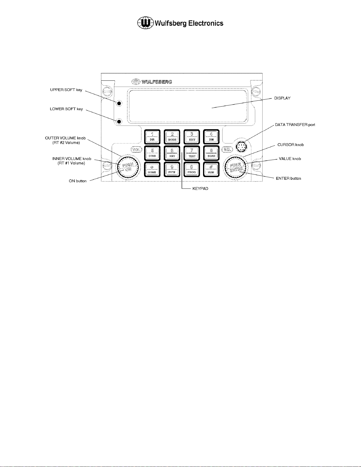
Front Panel & Controls
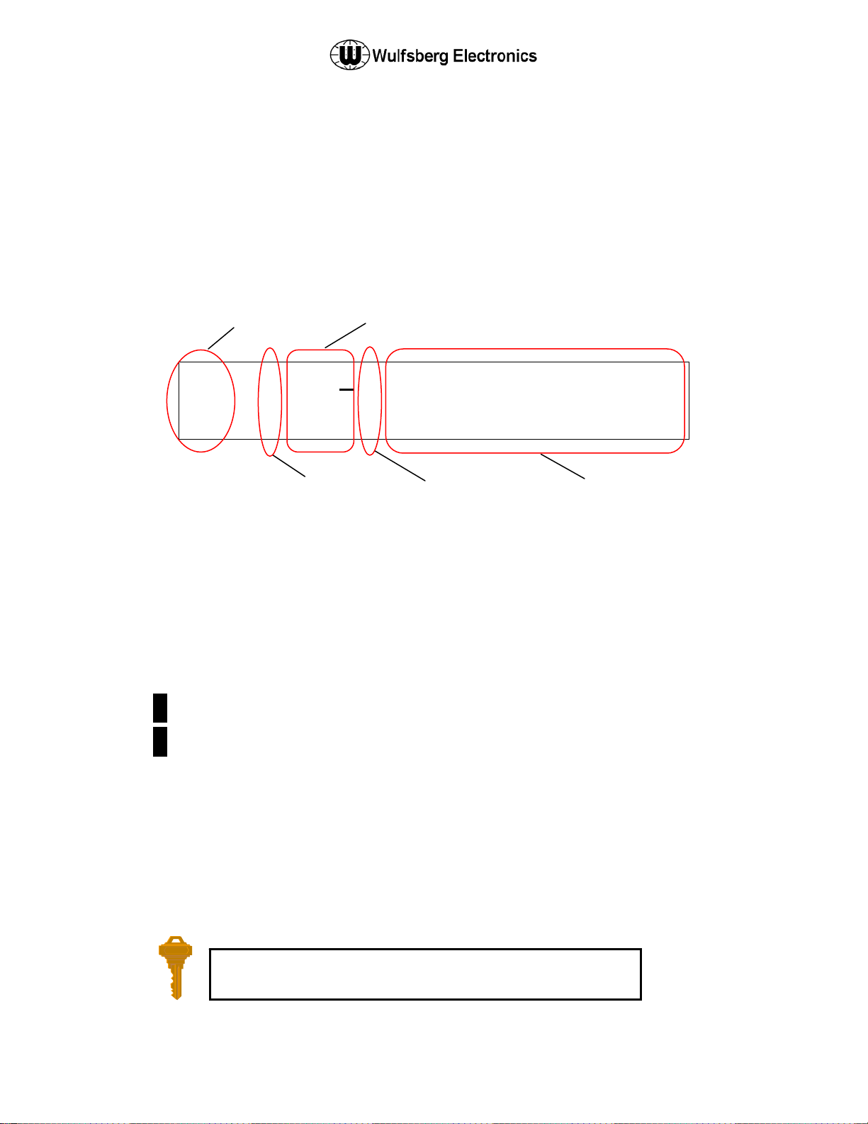
DISPLAY - The C-5000 has a 2 line display, with 20 characters on each line. It provides the visual
feedback for the system. Exactly what is displayed depends on the current operating mode of the C-
5000. During normal operation, the top line shows information for transceiver #1 and the bottom line
shows information for transceiver #2.
UPPER SOFT key – This key’s use depends on the current operating mode of the C-5000. Some
examples of its use are: increasing the display brightness and selecting radio 1’s guard receiver.
LOWER SOFT key - This key’s use depends on the current operating mode of the C-5000. Some
examples of its use are: decreasing the display brightness and selecting radio 2’s guard receiver.
OUTER VOLUME knob – This rotary switch is used to control the volume of radio 2.
INNER VOLUME knob – This rotary switch is used to control the volume of radio 1.
ON button – This button is used to turn the C-5000 on or off.
CURSOR knob – This rotary switch is used to move the cursor around the display.
VALUE knob – This rotary switch is used to modify values above the cursor.
ENTER button – This button’s use is dependent on the C-5000’s current operating mode, but is primarily
used to finalize data entry operations.
DATA TRANSFER PORT – This serial port is used to transfer data between the C-5000 and the
Wulfsberg Remote Programmer software. While preset channels can be programmed from the front
panel, the best method is to use a PC and the Wulfsberg Remote Programming (RP) software.
Publication No. 150-041103 Page 9 of 51
Rev. C C-5000 Pilot’s Guide
Nov 2013
C-5000 Pilot’s Guide
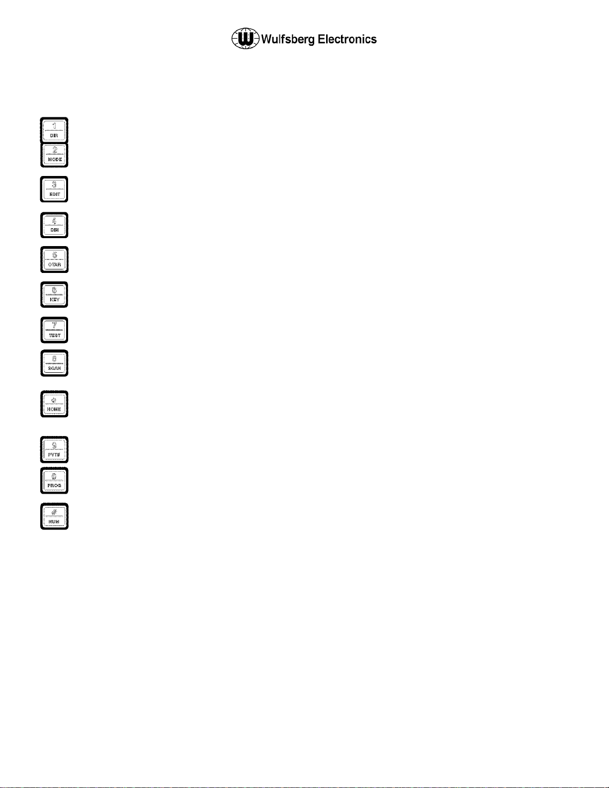
KEYPAD – The C-5000 has a 12 button keypad. Each button’s primary functions are described below.
1:DIR Toggles the transceiver under cursor control in and out of DIRECT mode. Use this button to enter
a “1” during keypad entry mode.
2:MODE This button will cycle through the enhanced modes of operation. Use this button to enter a “2”
during keypad entry mode.
3:EDIT This button will display the EDIT PAGE for the transceiver under cursor control. Use this button
to enter “3” during keypad entry mode.
4:DIM This button will display the page used to control the display’s brightness. Use this button to enter
a “4” during keypad entry mode.
5:OTAR This button will initiate an “Over The Air Rekey” for the transceiver under cursor control . Use
this button to enter a “5” during keypad entry mode.
6:KEY This button will prompt the user for a transmit encryption key to override the preset value for the
transceiver under cursor control. Use this button to enter a “6” during keypad entry mode.
7:TEST This button will override the squelch system of the radio under cursor control, allowing the user
to set the volume level. Use this button to enter a “7” during keypad entry mode
8:SCAN FUNCTION NOT AVAILABLE AT THIS TIME. Use this button to enter a “8” during keypad
entry mode.
*:HOME This button will display the HOME PAGE, except in some advanced modes of operation,
where it will return the user to a previous page or mode of operation. Use this button to enter a “*”
during keypad entry mode.
9:PVT This button will toggle the transceiver under cursor control in and out of private mode. Use this
button to enter a “9” during keypad entry mode.
0:PROG This button will display the programming password page. Use this button to enter a “0” during
keypad entry mode.
#:NUM This button will select keypad entry mode, such as for entering a channel number or frequency
using the keypad. Use this button to enter a “#” during keypad entry mode.
Publication No. 150-041103 Page 10 of 51
Rev. C C-5000 Pilot’s Guide
Nov 2013
LUK
EAFBT
TACTI
CAL
-
d
C-5000 Pilot’s Guide
The Home Page
The HOME PAGE is the primary operational page of the C-5000. The HOME PAGE becomes visible
when the C-5000 is ready for user input, immediately after the power up and initialization sequences have
completed. The C-5000 can control two radios. When viewing the HOME PAGE, Radio 1 is always
displayed on the top line. Radio 2 is always displayed on the bottom line. Virtually all keypad-initiated
operations are performed on the radio under cursor control. The radio under cursor control is the radio
whose line the cursor is currently located on. The cursor can be quickly toggled between radios (display
lines) by pressing the ENTER button.
The following illustration is an example of what the HOME PAGE looks like.
1 1 2 3
2
Main/Guard Status Fields – These fields display symbols indicating the current status of all the available
transceivers in the system. The symbols are as follows.
Main/Guard
Status Field
. . 1
Channel Selection Fiel
Encryption
Status Field
Direct Mode
Status Field
W R 1
0 0 1
Alphanumeric
Identifier Field
. – Indicates a radio is available, but not enabled.
► – Indicates a radio is transmitting.
1 – Indicates radio 1 is available and enabled.
2 – Indicates radio 2 is available and enabled.
1 – Indicates radio 1 is receiving.
2 – Indicates radio 2 is receiving.
Encryption Status Field – This field displays the encryption indicator symbol (
turned on, or a blank if encryption is turned off.
Channel Selection Field – This field displays the currently selected channel.
Direct Mode Status Field – This field displays the direct mode indicator symbol () when the current
channel is a direct channel, or the channel has been forced to be a direct channel by pressing the
DIR button.
Alphanumeric Identifier Field – This field displays the 12 character name of the currently selected
channel, unless the manual channel is selected, in which case the manual channel’s receive
frequency will be displayed.
You can always get back to the HOME PAGE by pressing the HOME
button one or more times.
Publication No. 150-041103 Page 11 of 51
Rev. C C-5000 Pilot’s Guide
Nov 2013
) when encryption is
CAUTI
ON!
GSYST
EMO
H
GEDIS
P
BRIGH
TNE
S
C-5000 Pilot’s Guide
Turning the System On and Off
To power the C-5000 ON, press and hold the ON button for approximately one second. When
initialization is complete, the HOME PAGE will appear on the display.
To power the C-5000 OFF, press and hold the ON button for several seconds. The following message
flashes on the display several times:
! ! ! U S E
T U R N I N
Continue to hold the ON button until the message stops flashing and the display turns off.
Setting the Display Brightness
When you first power ON the C-5000, the display is at its maximum brightness. To adjust the brightness
level, ensure you are on the HOME PAGE, then press the DIM button. The display will appear as follows.
U P C
AN
D O W N
Press the UPPER SOFT KEY to brighten the display. Press the LOWER SOFT KEY to dim the display.
Press the HOME button to return to the HOME PAGE.
NOTE:
The DIM key can be configured to invoke the MUTE function instead of the DIM function.
In this case, you must press the MODE button several times to access the display
brightness page.
! !
F F
L A Y
S
Setting the Volume Level
When you first power ON the C-5000, the volume level will be set to the level that was active when the
unit was powered down. You can change the volume level as follows.
Radio 1
Place the cursor on the top line of the display.
Tune to a channel with activity on it or press the TEST button. This will unsquelch the radio, allowing
you to hear the current volume level.
Rotate the INNER VOLUME knob clockwise to increase the volume level, or counterclockwise to
decrease the volume level.
Publication No. 150-041103 Page 12 of 51
Rev. C C-5000 Pilot’s Guide
Nov 2013
LUK
EAFBT
TACTI
CAL
-
LUK
EAFBT
TACTI
CAL
-
=..
0<ENT
E R >
TACTI
CAL
-
C-5000 Pilot’s Guide
Radio 2
Place the cursor on the bottom line of the display.
Tune to a channel with activity on it or press the TEST button. This will unsquelch the radio, allowing
you to hear the current volume level.
Rotate the OUTER VOLUME knob clockwise to increase the volume level, or counterclockwise to
decrease the volume level.
Selecting a Preset Channel Using the Cursor/Value Knob
When the C-5000 first powers on, the selected channels will be set to those that were active when the
unit was powered down. To select a different preset channel, do one of the following:
Move the cursor under the least significant digit of the channel number you want to change. The
illustration below shows a user preparing to change the channel for radio 1.
1 1 2 3
W R 1
2
Turn the VALUE knob clockwise to select the next available channel with a higher number. Turn the
VALUE knob counterclockwise to select the next available channel with a lower number. Keep
turning the VALUE knob until the desired channel is selected.
You can also increment the channel number by 10’s and 100’s. You do this by placing the cursor under
the 10’s or 100’s digit and turning the VALUE knob as described above. The following illustration depicts
the cursor under the 10’s digit. The 100’s digit would be one to the left of the 10’s digit.
1 1 2 3
2
Selecting a Channel Using the Keypad
Occasionally, it is desirable to select a preset channel by entering its number via the keypad, rather than
dialing it in with the cursor/value knobs. This can be performed as follows.
Place the cursor under any digit of the channel number you want to change.
Press the NUM button. The following illustration depicts the display after the NUM button has been
pressed while radio 1 was under cursor control.
. . 1
. . 1
0 0 1
W R 1
0 0 1
1 C H A N
2
Publication No. 150-041103 Page 13 of 51
Rev. C C-5000 Pilot’s Guide
Nov 2013
. . 1
0 0 1
LUK
EAFBT
TACTI
CAL
-
156.200
TACTI
CAL
-
C-5000 Pilot’s Guide
Input the channel number using the keypad buttons.
Press the ENTER button.
The input channel number will be selected, assuming it was a valid channel. If you input an invalid
channel number, the display will reappear as depicted above, giving you the opportunity to input a valid
channel number. You can press the HOME button to cancel the input operation and return to the HOME
PAGE.
Selecting a Channel by Alphanumeric Identifier
It is sometimes desirable to select a preset channel by name as opposed to number. This can be
performed as follows.
Place the cursor under the alphanumeric identifier field of the radio you want to tune the channel on.
The following illustration shows the cursor under radio 1’s alphanumeric identifier field.
1 1 2 3
W R 1
2
Rotate the VALUE knob clockwise to select the next channel in alphabetic order. Turning the VALUE
knob counterclockwise will select the previous channel in alphabetic order. Continue to turn the
VALUE knob until the desired channel is displayed.
1) The manual channel cannot be selected since it doesn’t have an alpha identifier!
NOTE:
2) The cursor will not move under the alphanumeric identifier field if the manual channel
is selected.
Selecting the Manual Channel
The manual channel is used to tune channels not already programmed as presets into the C-5000’s
memory. Each radio has its own manual channel. The manual channel is located at channel number 0,
and is displayed as “..M”. You can select the manual channel by either entering channel 0 from the
keypad, or by dialing it in using the cursor/value knobs. The following illustration depicts a C-5000 with
the manual channel for radio 1 selected.
1 . . M
2
. . 1
. . 1
0 0 1
0 0 1
The manual channel’s frequency is displayed in place of the alphanumeric identifier for preset channels.
Once the manual channel is selected, press the EDIT button to edit the channel information. The C-5000
automatically stores the manual channel information on power down.
Publication No. 150-041103 Page 14 of 51
Rev. C C-5000 Pilot’s Guide
Nov 2013
LUK
EAFBT
TACTI
CAL
-
300.000
T
TACTI
CAL
-
LUK
EAFBT
TACTI
CAL
-
IOOFF
TACTI
CAL
-
C-5000 Pilot’s Guide
Receiving/Transmitting
Receiving
The C-5000 is constantly monitoring its radios for reception. When a signal is received, the C-5000 will
light the receive indicator for the receiving radio, and route the audio to the operator’s headset (Assuming
the associated intercom switch is selected). The following illustration depicts radio 1 receiving.
1 1 2 3
2
Transmitting
To transmit on a radio system, select the appropriate source on your audio panel, and key the
microphone. Transmission will begin on the radio’s currently selected channel. During the transmission,
the radio’s transmit indicator will light, and the channel’s transmit frequency will be displayed. The
following illustration depicts radio #1 transmitting.
►
2
Enabling/Disabling Transceivers
You can enable (turn audio on) or disable (turn audio off) any radio under the C-5000’s control.
RX Indicator
. . 1
TX Indicator
1 2 3
. . 1
W R 1
0 0 1
0 0 1
Disabling (Turning Off) a Transceiver
Place the cursor under the R/T status indicator. The following illustration shows the cursor under
Radio #1’s status indicator.
1 1 2 3
2
Rotate the VALUE knob once in either direction. The display will indicate the radio has been turned
off, as the following illustrates.
. . 1
. R A D
2
Publication No. 150-041103 Page 15 of 51
Rev. C C-5000 Pilot’s Guide
Nov 2013
. . 1
W R 1
0 0 1
0 0 1
LUK
EAFBT
IOOFF
LUK
EAFBT
TACTI
CAL
-
LUK
EAFBT
TACTI
CAL
-
r
C-5000 Pilot’s Guide
Enabling (Turning On) a Transceiver
Place the cursor under the radio’s status indicator. The following illustration shows the cursor under
radio 2’s status indicator.
1 1 2 3
W R 1
. R A D
Rotate the VALUE knob once in either direction. The display will indicate the radio has been turned
on, as the following illustrates.
1 1 2 3
2
Using the Direct/Repeat Feature
The C-5000 supports both direct and repeat modes of operation. Any preset channel that has identical
transmit and receive frequencies is considered a direct channel. If the transmit and receive frequencies
are different, the C-5000 considers the channel a repeater channel. Repeater channels can be
temporarily changed into direct channels by pressing the DIR button. This will temporarily copy the
receive frequency into the transmit frequency, and the direct mode indicator will light. The following
illustration shows radio 1 in direct mode.
. . 1
1 1 2 3
Direct Mode Indicato
W R 1
0 0 1
W R 1
2
NOTE:
Publication No. 150-041103 Page 16 of 51
Rev. C C-5000 Pilot’s Guide
Nov 2013
Pressing the DIR button on a direct channel has no effect.
. . 1
0 0 1
 Loading...