

Wulfsberg C-5000 Installation Manual

C-5000 COMMUNICATION MANAGEMENT CONTROLLER
INSTALLATION MANUAL
Wulfsberg Electronics Division, located in Prescott, Arizona, designs and manufactures the
C-5000 Communication Management Controller
Wulfsberg Electronics Division makes no warranty, expressed or implied, with regard to this
manual, including but not limited to any implied warranties of merchantability, fitness for a
particular purpose, and non-infringement. In addition, Wulfsberg Electronics Division makes no
warranty with regard to the documentation or data contained herein. Wulfsberg Electronics
Division is not liable in the event of incidental, special, consequential, or any other damages in
connection with or arising from furnishing, performance, or use of this manual.
Reproduction of this publication or any portion thereof by any means is prohibited. For further
information contact Sales, Wulfsberg Electronics Division, 6400 Wilkinson Drive, Prescott,
Arizona, 86301. Telephone: (928) 708-1500.
Information in this manual is subject to change without notice.
2001 Wulfsberg Electronics Division. All rights reserved
C-5000 is a trademark of Wulfsberg Electronics Division.
PROPRIETARY NOTICE
This document contains proprietary information and such information may not be disclosed to
others for any purpose, nor used for manufacturing purposes without written permission from
Wulfsberg Electronics Division.
Page ii Publication No. 150-041118
Table of Contents Rev A
Sep 2001

C-5000 COMMUNICATION MANAGEMENT CONTROLLER
INSTALLATION MANUAL
Record of Revisions
Rev
No.
A9/2001
Rev
Date
Date
Inserted By
Rev
No.
Rev
Date
Date
Inserted By
Publication No. 150-041118 Page iii
Rev A Table of Contents
Sep 2001

C-5000 COMMUNICATION MANAGEMENT CONTROLLER
INSTALLATION MANUAL
Record of Revisions
Rev
No.
Rev
Date
Date
Inserted By
Rev
No.
Rev
Date
Date
Inserted By
Page iv Publication No. 150-041118
Table of Contents Rev A
Sep 2001

C-5000 COMMUNICATION MANAGEMENT CONTROLLER
INSTALLATION MANUAL
TABLE OF CONTENTS
Section 1 - Introduction
1. Using This Manual...................................................................................................... 1-1
2. Components ............................................................................................................... 1-2
A. Communication Managem ent Controller....................................................... 1-2
B. FLEXCOMM II ............................................................................................... 1-2
C. FLEXCOMM I................................................................................................ 1-3
D. Part Numbering.............................................................................................. 1-4
Section 2 - System Installation
1. General.......................................................................................................................2-1
2. System Specifications................................................................................................. 2-1
Page
A. C-5000 Communication Management Controller.......................................... 2-1
B. FLEXCOMM II ............................................................................................... 2-2
C. FLEXCOMM I................................................................................................ 2-8
3. System Interface......................................................................................................... 2-9
A. C-5000 Control Unit/FLEXCOMM II RT System Interface .......................... 2-10
B. C-5000 Control Unit/FLEXCOMM I RT System Interface ........................... 2-11
C. C-5000 Control Unit/Hybrid FLEXCOMM II/FLEXCOMM I Interface.......... 2-12
4. System Operational Modes ...................................................................................... 2-13
A. Single Channel Normal Operation............................................................... 2-13
B. Simulcast Operation .................................................................................... 2-13
C. Relay Operation........................................................................................... 2-13
D. Relay with Simulcast Operation................................................................... 2-13
E. Repeater Operation..................................................................................... 2-13
F. Dual C-5000 Operation................................................................................ 2-13
Publication No. 150-041118 Page v
Rev A Table of Contents
Sep 2001

C-5000 COMMUNICATION MANAGEMENT CONTROLLER
INSTALLATION MANUAL
TABLE OF CONTENTS (cont’d)
SECTION 3 – MECHANICAL INSTALLATION
1. General.......................................................................................................................3-1
2. Unpacking and Inspecting Equipment........................................................................ 3-1
3. General Installation Requirements ............................................................................. 3-2
A. Component Weights...................................................................................... 3-2
4. Installation of Multipin Crimp Connectors................................................................... 3-3
A. Contacts and Crimp Tool Information............................................................ 3-3
B. Contacts and Insertion/Removal Tool Manufacturer Name and Address..... 3-3
5. Installation of C-5000.................................................................................................. 3-3
6. Installation of RT-5000................................................................................................ 3-3
Page
7. Installation of Antennas .............................................................................................. 3-4
A. AT-560 / AT-5000 .......................................................................................... 3-4
B. FC-50............................................................................................................. 3-4
C. AT-550........................................................................................................... 3-4
D. FC-5000......................................................................................................... 3-4
E. AT-50 and AT-51........................................................................................... 3-4
F. FC-50............................................................................................................. 3-5
G. AT-400........................................................................................................... 3-5
H. AT-140........................................................................................................... 3-5
SECTION 4 - ELECTRICAL INSTALLATION
1. General.......................................................................................................................4-1
2. Wiring Considerations................................................................................................. 4-1
A. C-5000 System Interface Connector, P500................................................... 4-2
B. C-5000 Transceiver Interface, RT-5000...................................................... 4-13
C. RT-=5000 Transceiver Installation .............................................................. 4-17
D. C-5000 Communication Management Controller Installation...................... 4-35
E. C-5000 Transceiver Interface FLEXCOMM................................................. 4-37
F. C-5000 Transceiver Interface...................................................................... 4-47
Page vi Publication No. 150-041118
Table of Contents Rev A
Sep 2001

C-5000 COMMUNICATION MANAGEMENT CONTROLLER
INSTALLATION MANUAL
TABLE OF CONTENTS (cont’d)
SECTION 5 – CONFIGURATION AND PROGRAMMING
Introduction.............................................................................................................................. 5-1
Features...................................................................................................................... 5-1
Transceiver Overview................................................................................................. 5-1
Steps to Successful Setup and Operation.................................................................. 5-3
Basic Operation ....................................................................................................................... 5-4
Front Panel & Controls ............................................................................................... 5-4
The Home Page.......................................................................................................... 5-6
Turning the System On and Off.................................................................................. 5-7
Setting the Display Brightness.................................................................................... 5-7
Setting the Volume Level............................................................................................ 5-7
Page
Selecting a Preset Channel Using the Cursor/Value Knob........................................ 5-8
Selecting a Channel Using the Keypad...................................................................... 5-8
Selecting a Channel by Alphanumeric Identifier......................................................... 5-9
Selecting the Manual Channel.................................................................................... 5-8
Using the Direct/Repeat Feature .............................................................................. 5-10
Receiving/Transmitting............................................................................................. 5-10
Enabling/Disabling Transceivers .............................................................................. 5-11
Publication No. 150-041118 Page vii
Rev A Table of Contents
Sep 2001

C-5000 COMMUNICATION MANAGEMENT CONTROLLER
INSTALLATION MANUAL
TABLE OF CONTENTS (cont’d)
SECTION 5 –CONFIGURATION AND PROGRAMMING (cont’d)
Disabling (Turning Off) a Transceiver.......................................................... 5-11
Enabling (Turning On) a Transceiver .......................................................... 5-11
Using the Edit Page............................................................................................................... 5-13
Editing a Preset Channel.......................................................................................... 5-13
Editing a Manual Channel......................................................................................... 5-14
Changing PL and DPL (CTCSS and DCS) Tones ................................................... 5-14
Turning Tones Off........................................................................................ 5-14
Selecting a CTCSS Tone ............................................................................ 5-15
Selecting a DCS Tone ................................................................................. 5-15
Changing Transmit Power........................................................................................ 5-16
Changing Modulation Type....................................................................................... 5-16
Page
Changing Receiver Bandwidth................................................................................. 5-17
Enhanced System Features .................................................................................................. 5-18
Phone Patch Mode................................................................................................... 5-18
Simulcast Operation ................................................................................................. 5-18
Relay Operation........................................................................................................ 5-19
Relay/Simulcast Operation....................................................................................... 5-20
Repeater Operation .................................................................................................. 5-21
Encryption Features............................................................................................................... 5-22
Turning Encryption On and Off................................................................................. 5-22
Selecting an Encryption Key..................................................................................... 5-22
Performing an OTAR ................................................................................................ 5-23
Erasing Encryption Keys........................................................................................... 5-24
Manually Loading Encryption Keys .......................................................................... 5-25
Programming Preset Channels.............................................................................................. 5-27
Programming Preset Channels Using the Front Page ............................................. 5-27
Page viii Publication No. 150-041118
Table of Contents Rev A
Sep 2001

C-5000 COMMUNICATION MANAGEMENT CONTROLLER
INSTALLATION MANUAL
TABLE OF CONTENTS (cont’d)
SECTION 5 –CONFIGURATION AND PROGRAMMING (cont’d)
Configuring the C-5000..........................................................................................................5-32
Configuring the C-5000............................................................................................. 5-32
Configuring the C-5000 to Control an RT-5000........................................................ 5-34
Configuring the C-5000 to Control a Non RT-5000 .................................................. 5-35
Setting Passwords.................................................................................................... 5-38
Setting Miscellaneous Configuration Options........................................................... 5-39
Configuring the C-5000 Using a PC ......................................................................... 5-40
Downloading a Configuration from RP into the C-5000 .............................. 5-40
Uploading a Configuration from the C-5000 into RP................................... 5-41
RSS Software Description and Programming ....................................................................... 5-43
Page
Before You Begin...................................................................................................... 5-43
Main Menu Operations ............................................................................................. 5-43
Personality Programm ing (Conventional Ana log FM Person al ities ) ........................ 5-50
Personality Programm ing (Conventional P25 Persona liti es).................................... 5-53
Glossary................................................................................................................................. 5-58
Appendix A – CTCSS (PL) Tone Codes................................................................................ 5-61
Appendix B – Mode 2 Operation............................................................................................ 5-63
Publication No. 150-041118 Page ix
Rev A Table of Contents
Sep 2001

C-5000 COMMUNICATION MANAGEMENT CONTROLLER
INSTALLATION MANUAL
TABLE OF CONTENTS (cont’d)
SECTION 6 – SYSTEM VERIFICATION PROCEDURE
1. General.......................................................................................................................7-1
2. System Checkout........................................................................................................ 7-1
Page
Page x Publication No. 150-041118
Table of Contents Rev A
Sep 2001

C-5000 COMMUNICATION MANAGEMENT CONTROLLER
INSTALLATION MANUAL
SECTION 1 - INTRODUCTION
IMPORTANT
This manual contains information pertaining to the installation of the C-5000
Communication Management Controller with FLEXCOMM II and FLEXCOMM I.
FLEXCOMM II consists of the RT-5000 Transceiver, appropriate antennas, and optional
equipment as required. FLEXCOMM I consists of the RT-9600 Transceiver, RT-9600F
Transceiver, RT-7200 Transceiver, and optional combinations of up to three of the
following FLEXCOMM Transceivers: RT-30, RT-118, RT-138(F), RT-406F, RT-450,
appropriate antennas, and optional equipment as required. The C-5000 can also
interface with combined applications of FLEXCOMM II and FLEXCOMM I, i.e., a hybrid
RT System configuration that consists of both RT-5000 and FLEXCOMM I Transceivers.
1. Using This Manual
This manual is divided into the following sections:
SECTION 1- INTRODUCTION
This section contains an overview of the contents of this manual and lists the components
installed in FLEXCOMM I and FLEXCOMM II systems using the C-5000.
SECTION 2 - SYSTEM INSTALLATION
This section covers the general system characteristics, interface capabilities and power
requirements.
SECTION 3 - MECHANICAL INSTALLATION
This section contains system component dimensions, the racking requirements, weights, and
component installation dat a.
SECTION 4 - FLEXCOMM II ELECTRICAL INSTALLATION
This section contains the wiring information to install the C-5000 Control Unit with the
FLEXCOMM II Transceiver in an airc raft.
SECTION 5 - FLEXCOMM I ELECTRICAL INSTALLATION
This section contains the wiring information to install the C-5000 Control Unit with the
FLEXCOMM I Transceiver in an airc r af t.
SECTION 6 - SYSTEM CONFIGURATION AND PRESET CHANNEL PROGRAMMING
This section contains the system configuration and preset channel programming procedures
for the system.
SECTION 7 - SYSTEM CHECKOUT
This section contains checkout procedure for the system after installation.
Publication No. 150-041118 Page 1-1
Rev A Section 1 - Introduction
Sep 2001

C-5000 COMMUNICATION MANAGEMENT CONTROLLER
INSTALLATION MANUAL
2. Components
The following components can be installed:
A. Communication Management Controller
C-5000 PN 31300-1X02-1XX0 (See Figure 1-1)
B. FLEXCOMM II
(1) Transceivers
RT-5000 PN 400-015525-XXXX (See Table 1-1)
(2) Antennas Systems (Refer to Table 1-2)
AT-560 PN 121-040130-XX
AT-160 PN 121-040129-01
AT-5000 PN 121-040045-01
AT-550 PN 121-017850-01
AT-150 PN 153-017822-01
AT-50 PN 121-016587-01
AT-51 PN 121-016796-01
AT-140 PN 121-016584-01
AT-400 PN 121-16821-01
FC-50 Logic Converter PN 153-016586-01
FC-5000 Logic Converter PN 153-040047-01
FC-550 Logic Converter PN 153-017851
(3) RT-5000 Mounting Trays
Vertical Mounting Tray PN 300-316605-01
Horizontal Mounting Tray PN 300-316835-01
Page 1-2 Publication No. 150-041118
Section 1 - Introduction Rev A
Sep 2001

C-5000 COMMUNICATION MANAGEMENT CONTROLLER
C. FLEXCOMM I
(1) Transceivers
RT-30 PN 400-0098-XXX (See Table 1-3)
RT-118 PN 400-0119-XXX (See Table 1-4)
RT-138 PN 400-0102-XXX (See Table 1-5)
RT-138F PN 400-014525-XX/5X (See Table 1-6)
RT-406F PN 400-012785-XX/5X (See Table 1-7)
RT-450 PN 400-0103-XXX (See Table 1-8)
RT-7200 PN 400-0087-XXX (See Table 1-9)
RT-9600 PN 400-0052-XXX (See Table 1-10)
RT-9600F PN 400-0140-XXXX (See Table 1-11)
INSTALLATION MANUAL
(2) Antennas
AT-35 System PN 121-014235-XX
AT-270 PN 121-0002-000
AT-461 PN 121-0011-000
AT-462 PN 121-014378-01
AT-695 PN 121-0019-000
AT-960 PN 121-0010-000
Note: Refer to the following for information on FLEXCOMM I antennas and
installation:
a FLEXCOMM I Installation Manual, WED Manual No. 150-040011-000, for
information on FLEXCOMM Antennas.
b WED Manual No. 150-0061-000 for information on RT-9600 and RT-7200
Antennas.
Publication No. 150-041118 Page 1-3
Rev A Section 1 - Introduction
Sep 2001
C-5000 COMMUNICATION MANAGEMENT CONTROLLER
INSTALLATION MANUAL
D. Part Numbering
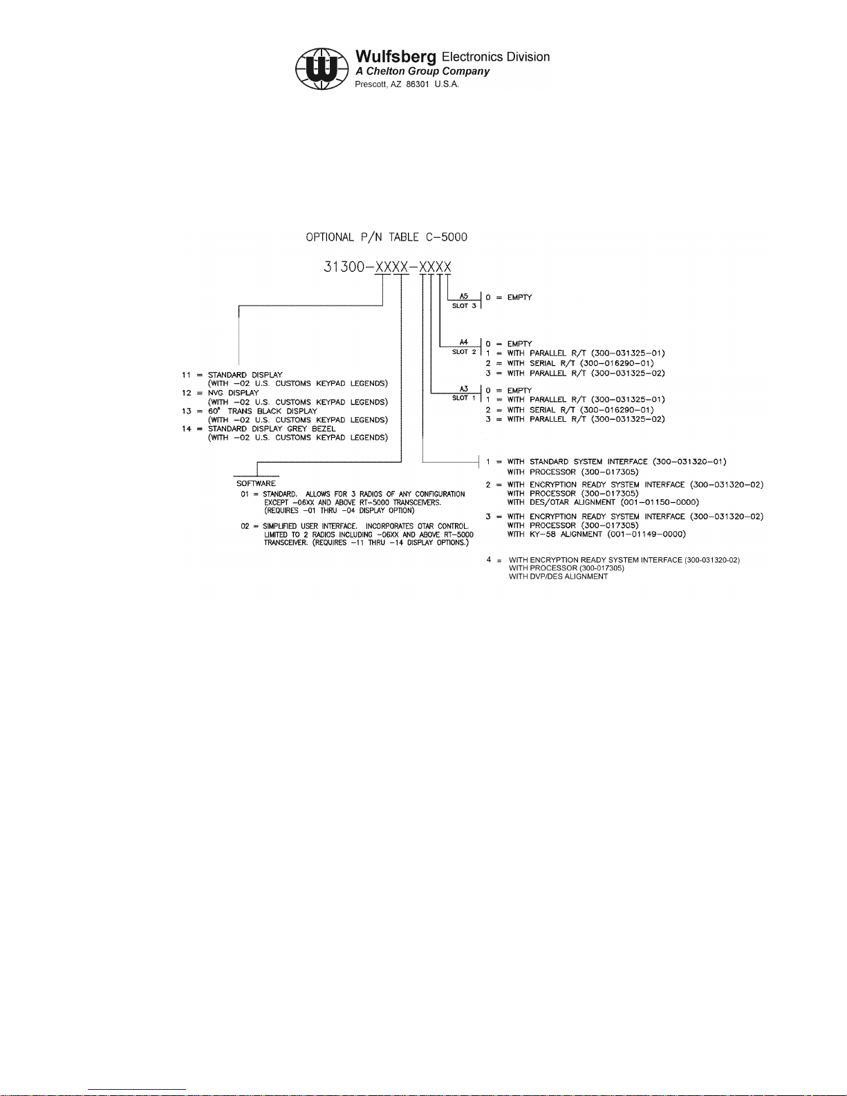
The C-5000's basic unit part number 31300-XXXX-XXXX is configured as follows:
Figure 1-1. C-5000 Part Numbering
Note: Processor board PN 300-031315 can only be used with Parallel R/T board
PN 300-031325. Processor board PN 300-017305 can be used with Parallel
R/T PN 300-031325 and Serial R/T board PN 300-016290.
The installation and operation of the Frequency Agile C-5000 Control Unit is
limited to aircraft installations per FCC Rules and Regulations, Part 90, Section
90.423 and 90.203(h). A non-frequency agile C-5000 is available for other than
aircraft installations and is in compliance with FCC Rules and Regulations
90.203(g).
Page 1-4 Publication No. 150-041118
Section 1 - Introduction Rev A
Sep 2001

C-5000 COMMUNICATION MANAGEMENT CONTROLLER
INSTALLATION MANUAL
Table 1-1. RT-5000 Part Numbers
Part Number RT-5000 Description
400-015525-0101 Transceiver, No Guard Receiver
400-015525-0201 Transceiver, Crystal Controlled Guard Receiver, 30MHz -50MHz
400-015525-0301 Transceiver, Crystal Controlled Guard Receiver, 138 MHz - 174 MHz
400-015525-0401 Transceiver, Crystal Controlled Guard Receiver, 406 MHz - 512 MHz
400-015525-0501 Transceiver, Synthesized Guard
400-015525-0611 Transceiver, D.E.S. Encrypted VHF 138-174 MHz MTM Guard Receiver
400-015525-0711 Transceiver, VHF 138 MHz MTM Guard Receiver
400-015525-0811 Transceiver, D.E.S. Encrypted UHF403 MHz MTM Guard Receiver
400-015525-0911 Transceiver, UHF403 MHz MTM Guard Receiver
400-015525-1011 Transceiver, D.E.S. Encrypted UHF450-520 MHz MTM Guard Receiver
400-015525-1111 Transceiver, UHF520 MHz MTM Guard Receiver
400-015525-1211 Transceiver, D.E.S. Encrypted UHF800 Trunk MHz MTM Guard Receiver
400-015525-1311 Transceiver, UHF800 MHz MTM Guard Receiver
400-015525-1411 Transceiver, D.E.S. Encrypted VHF138 MHz MTM Guard Receiver and
UHF800 MHz MTM Guard Receiver
400-015525-1511 Transceiver, VHF138 MHz MTM Guard Receiver and UHF800 MHz MTM
Guard Receiver
400-015525-1611 Transceiver, D.E.S. Encrypted VHF138 MHz MTM Guard Receiver and D.E.S.
Encrypted UHF800 MHz MTM Guard Receiver
400-015525-1711 Transceiver, VHF138 MHz MTM Guard Receiver and D.E.S. Encrypted
UHF800 MHz MTM Guard Receiver
400-015525-1811 Transceiver, D.E.S. Encrypted VHF138 MHz MTM Guard Receiver and
UHF520 MHz MTM Guard Receiver
400-015525-1911 Transceiver, VHF138 MHz MTM Guard Receiver and UHF520 MHz MTM
Guard Receiver
400-015525-2011 Transceiver, D.E.S. Encrypted VHF138 MHz MTM Guard Receiver and D.E.S.
Encrypted UHF520 MHz MTM Guard Receiver
400-015525-2111 Transceiver, VHF138 MHz MTM Guard Receiver and D.E.S. Encrypted
UHF520 MHz MTM Guard Receiver
400-015525-2211 Transceiver, D.E.S. Encrypted VHF138 MHz MTM Guard Receiver and
UHF403 MHz MTM Guard Receiver
Publication No. 150-041118 Page 1-5
Rev A Section 1 - Introduction
continues…
Sep 2001

C-5000 COMMUNICATION MANAGEMENT CONTROLLER
INSTALLATION MANUAL
Table 1-1. RT-5000 Part Numbers (cont’d)
Part Number RT-5000 Description
400-015525-2311 Transceiver, VHF138 MHz MTM Guard Receiver and UHF403 MHz MTM
Guard Receiver
400-015525-2411 Transceiver, D.E.S. Encrypted VHF138 MHz MTM Guard Receiver and D.E.S.
Encrypted UHF403 MHz MTM Guard Receiver
400-015525-2511 Transceiver, VHF138 MHz MTM Guard Receiver and D.E.S. Encrypted
UHF403 MHz MTM Guard Receiver
400-015525-2611 Transceiver, DVI-XL UHF520 MHz MTM Guard Receiver
400-015525-2711 Transceiver, DVI-XL UHF800 MHz MTM Guard Receiver
Table 1-2. FLEXCOMM II Antenna Part Numbers
Part Number Antenna Description
121-040130-01 AT-560 -- 29.7 - 960 MHz 9.5” Tuned Multiband White
121-040130-02 AT-560 -- 29.7 - 960 MHz 9.5” Tuned Multiband Black
121-040129-01 AT-160 -- 29.7 – 960 MHz 9.5” Passive Multiband
121-040045-01 AT-5000 -- 29.7 – 960 MHz 5.5” (FC-5000 Req) White
121-040045-02 AT-5000 -- 29.7 – 960 MHz 5.5” (FC-5000 Req) Black
121-017850-01 AT-550 -- 29.7 – 960 MHz (FC-550 Req) White
153-017822-01 AT-150 -- 29.7 – 960 MHz (poor 30-88 MHz) White
121-016587-01 AT-50 -- 29.7 - 400MHz Autotuned Blade White
121-016796-01 AT-51 -- 29.7 - 400MHz Autotuned Blade White
121-016584-01 AT-140 -- 29.7MHz - 400MHz Blade White
121-016821-01 AT-400 -- 400MHz - 960MHZ Jet Blade White
153-016586-01 FC-50 Logic Converter -- Antenna Tuner for AT-50/51
153-040047-01 FC-5000 -- Antenna Tuner for AT-5000 and AT-560
153-017851 FC-550 Logic Converter
146-016958-01 Gasket, AT-400
146-014960-01 Gasket, AT-51
146-014959-01 Gasket, AT-50
Page 1-6 Publication No. 150-041118
Section 1 - Introduction Rev A
Sep 2001

C-5000 COMMUNICATION MANAGEMENT CONTROLLER
INSTALLATION MANUAL
Table 1-3. RT-30 Part Numbers
Part Number RT-30 Description
400-0098-000 Transceiver, FLEXCOMM Lo Band VHF, 29.70-49.99 MHz.
400-0098-001 Transceiver, FLEXCOMM Lo Band VHF, 29.70 - 49.99 MHz, with Guard
Receiver
400-0098-002 Transceiver, FLEXCOMM Lo Band VHF, 29.70 - 49.99 MHz, with Guard
Receiver and Guard Receiver CTCSS Tones.
Table 1-4. RT-118 Part Numbers
Part Number RT-118 Description
400-0119-000 Transceiver, FLEXCOMM VHF-AM Band 118.000 - 137.975 MHz,
Standard Receiver IF Bandwidth
400-0119-001 Transceiver, FLEXCOMM VHF-AM Band 118.000 - 137.975 MHz,
Wide Receiver IF Bandwidth
Table 1-5. RT-138 Part Numbers
Part Number RT-138 Description
400-0102-000 Transceiver, FLEXCOMM Hi Band VHF, 138.0000 - 173.9975 MHz
400-0102-001 Transceiver, FLEXCOMM Hi Band VHF, 138.0000 - 173.9975 MHz, with
Guard Receiver.
400-0102-002 Transceiver, FLEXCOMM Hi Band VHF, 138.0000 - 173.9975 MHz, with
Guard Receiver and Guard Receiver CTCSS Tones
400-0102-003 Transceiver, FLEXCOMM Hi Band VHF, 138.0000 - 173.9975 MHz, with
increased sensitivity (precludes Guard).
Publication No. 150-041118 Page 1-7
Rev A Section 1 - Introduction
Sep 2001

C-5000 COMMUNICATION MANAGEMENT CONTROLLER
INSTALLATION MANUAL
Table 1-6. RT-138F Part Numbers
Part Number RT-138F Description
400-014525-00 Transceiver, FLEXCOMM Hi Band VHF, 138.0000-173.9975 MHz.
400-014525-01 Transceiver, FLEXCOMM Hi Band VHF, 138.0000 - 173.9975 MHz, with
Guard Receiver.
400-014525-02 Transceiver, FLEXCOMM Hi Band VHF, 138.0000 - 173.9975MHz, with Guard
Receiver and Guard Receiver CTCSS Tones.
400-014525-03 Transceiver, FLEXCOMM Hi Band VHF, 138.0000 - 173.9975 MHz, with
increased sensitivity (precludes Guard).
400-014525-50 Transceiver, FLEXCOMM Hi Band VHF, 138.0000 - 173.9975 MHz, Voice
Encryption interface compatible.
400-014525-51 Transceiver, FLEXCOMM Hi Band VHF, 138.0000 - 173.9975 MHz, with
Guard Receiver, Voice Encryption interface compatible.
400-014525-52 Transceiver, FLEXCOMM Hi Band VHF, 138.0000 - 173.9975 MHz, with
Guard Receiver, Guard Receiver CTCSS Tones and Voice Encryption
interface compatible.
400-014525-53 Transceiver, FLEXCOMM Hi Band VHF, 138.0000 - 173.9975 MHz, with
increased sensitivity and Voice Encryption interface compatible (precludes
Guard).
Note: All RT-138F units are compatible with Voice Encryption systems utilizing Non Return to
Zero (NRZ) modulation at a data rate of 12 Kbit/sec or less. The -5X units are
specifically wired to readi l y interfac e with Motorola and General Electric encr ypti on
modules. Additionally, all RT-138F units are compatible with Digital Coded Squelch
Systems (Motorola Digital Private Line and GE Digital Channel Guard).
Page 1-8 Publication No. 150-041118
Section 1 - Introduction Rev A
Sep 2001

C-5000 COMMUNICATION MANAGEMENT CONTROLLER
INSTALLATION MANUAL
Table 1-7. RT-406F Part Numbers
Part Number RT-406F Description
400-012785-00 Transceiver, FLEXCOMM UHF Band, 406.0000 511.9875 MHz.
400-012785-01 Transceiver, FLEXCOMM UHF Band, 406-0000 511.9875 MHz, with Guard
Receiver.
400-012785-02 Transceiver, FLEXCOMM UHF Band, 406.0000 511.9875 MHz, with Guard
Receiver and Guard Receiver CTCSS Tones.
400-012785-03 Transceiver, FLEXCOMM UHF Band, 406.0000 511.9875 MHz, with increased
sensitivity (precludes Guard).
400-012785-50 Transceiver, FLEXCOMM UHF Band, 406.0000 511.9875 MHz, Voice
Encryption interface compatible
400-012785-51 Transceiver, FLEXCOMM UHF Band, 406.0000 511.9875 MHz, with Guard
Receiver, Voice Encryption interface compatible
400-012785-52 Transceiver, FLEXCOMM UHF Band, 406.0000 511.9875 MHz, with Guard
Receiver, Guard Receiver CTCSS Tones and Voice Encryption interface
compatible
400-012785-53 Transceiver, FLEXCOMM UHF Band, 406.0000 511.9875 MHz, with increased
sensitivity and Voice Encryption interface compatible (precludes Guard).
Note: All RT-406F units are compatible with Voice Encryption systems utilizing Non Return to
Zero (NRZ) modulation at a data rate of 12 Kbit/sec or less. The -5X units are
specifically wired to readi l y interfac e with Motorola and General Electric encr ypti on
modules. Additionally, all RT-406F units are compatible with Digital Coded Squelch
Systems (Motorola Digital Private Line and GE Digital Channel Guard).
Table 1-8. RT-450 Part Numbers
Part Number RT-450 Description
400-0103-000 Transceiver, FLEXCOMM UHF Band, 450.0000 - 469.9875 MHz.
400-0103-001 Transceiver, FLEXCOMM UHF Band, 450.0000 - 469.9875 MHz, with Guard
Receiver.
400-0103-002 Transceiver, FLEXCOMM UHF Band, 450.0000 - 469.9875 MHz, with Guard
Receiver and Guard Receiver CTCSS Tones.
400-0103-003 Transceiver, FLEXCOMM UHF Band, 450.0000 - 469.9875 MHz, with
increased sensitivity (precludes Guard).
Publication No. 150-041118 Page 1-9
Rev A Section 1 - Introduction
Sep 2001

C-5000 COMMUNICATION MANAGEMENT CONTROLLER
INSTALLATION MANUAL
Table 1-9. RT-7200 Part Numbers
Part Number RT-7200 Description
400-0087-000 Transceiver, RT-7200 VHF HI-Band, 138 .00 00 - 173 .99 5 MHz, 14/ 28 VDC,
100mW Audio, Recessed Connector.
400-0087-001 Transceiver, RT-7200 VHF HI-Band, 138.00 - 173.995 MHz, 14/28 VDC,
100mW Audio, Recessed Connector, with Guard Receiver.
400-0087-002 Transceiver, RT-7200 VHF HI-Band, 138 .00 00 - 173 .99 5 MHz, 14/ 28 VDC,
100mW Audio, Recessed Connector, with CTCSS Tones.
400-0087-003 Transceiver, RT-7200 VHF HI-Band, 138 .00 00 - 173 .99 5 MHz, 14/ 28 VDC,
100mW Audio, Recessed Connector, with Guard Receiver and CTCSS Tones.
Table 1-10. RT-9600 Part Numbers
Part Number RT-9600 Description
400-0052-002 Transceiver, RT-9600 VHF HI-Band, 150.0000 - 173.995 MHz, 14/28 VDC,
100 mW Audio, Protruding Connector
400-0052-005 Transceiver, RT-9600 VHF HI-Band, 150.0000 - 173.995 MHz, 14/28 VDC,
100 mW Audio, Protruding Connector, with Guard Receiver
400-0052-008 Transceiver, RT-9600 VHF HI-Band, 150.0000 - 173.995 MHz, 4/28 VDC,
100 mW Audio, Protruding Connector with CTCSS Tones
400-0052-011 Transceiver, RT-9600 VHF HI-Band, 150 .00 00 - 173 .99 5 MHz, 14/ 28 VDC,
100 mW Audio, Protruding Connector, with Guard Receiver and CTCSS Tones
400-0052-024 Transceiver, RT-9600 VHF HI-Band, 150.0000 - 173.995 MHz, 14/28VDC,
100 mW Audio, Recessed Connector
400-0052-025 Transceiver, RT-9600 VHF HI-Band, 150 .00 00 - 173 .99 5 MHz, 14/ 28 VDC,
100 mW Audio, Recessed Connector, with Guard Receiver
400-0052-026 Transceiver, RT-9600 VHF HI-Band, 150 .00 00 - 173 .99 5 MHz, 14/ 28 VDC,
100 mW Audio, Recessed Connector, with CTCSS Tones
400-0052-027 Transceiver, RT-9600 VHF HI-Band, 150 .00 00 - 173 .99 5 MHz, 14/ 28 VDC,
100 mW Audio, Recessed Connector, with Guard Receiver and CTCSS Tones
Page 1-10 Publication No. 150-041118
Section 1 - Introduction Rev A
Sep 2001

C-5000 COMMUNICATION MANAGEMENT CONTROLLER
INSTALLATION MANUAL
Table 1-11. RT-9600F Part Numbers
Part Number RT-9600F Description
400-0140-002 Transceiver, RT-9600F VHF HI-Ba nd, 150 .00 00 - 173.995 MH z, 14/2 8 VDC,
100 mW Audio, Protruding Connector
400-0140-005 Transceiver, RT-9600F VHF HI-Ba nd, 150 .00 00 - 173.995 MH z, 14/2 8 VDC,
100 mW Audio, Protruding Connector, with Guard Receiver
400-0140-008 Transceiver, RT-9600F VHF HI-Ba nd, 150 .00 00 - 173.995 MH z, 14/2 8 VDC,
100 mW Audio, Protruding Connector with CTCSS Tones
400-0140-011 Transceiver, RT-9600F VHF HI-Band, 14/ 28 VDC, 100 mW Audio, Protruding
Connector, with Guard Receiver and CTCSS Tones
400-0140-024 Transceiver, RT-9600F VHF HI-Band, 150.0000 - 173.995 MHz, 14/28VDC,
100 mW Audio, Recessed Connector
400-0140-025 Transceiver, RT-9600F VHF HI-Ba nd, 150 .00 00 - 173.995 MH z, 14/2 8 VDC,
100 mW Audio, Recessed Connector, with Guard Receiver
400-0140-026 Transceiver, RT-9600F VHF HI-Ba nd, 150 .00 00 - 173.995 MH z, 14/2 8 VDC,
100 mW Audio, Recessed Connector, with CTCSS Tones
400-0140-027 Transceiver, RT-9600F VHF HI-Ba nd, 150 .00 00 - 173.995 MH z, 14/2 8 VDC,
100 mW Audio, Recessed Connector, with Guard Receiver and CTCSS Tones
040-0140-052,
400-0140-152
Transceiver, RT-9600F VHF HI-Band, 150.0000 -173.995 MHz, 14/28 VDC,
100 mW Audio, Protruding Connector and Voice Encryption interface
compatible
400-0140-055,
400-0140-155
Transceiver, RT-9600F VHF HI-Ba nd, 150 .00 00 - 173.995 MHz, 14/28 VDC,
100 mW Audio, Protruding Connector, and Voice Encryption interface
compatible
400-0140-058,
400-0140-158
Transceiver, RT-9600F VHF HI-Band, 150.0000 - 173.995 MHz, 14/28 VDC,
100 mW Audio, Protruding Connector with CTCSS Tones, and Voice
Encryption interface compatible
400-0140-061,
400-0140-1611
Transceiver, RT-9600F VHF HI-Ba nd, 150 .00 00 - 173.995 MHz, 14/28 VDC,
100 mW Audio, Protruding Connector, with Guard Receiver and CTCSS
Tones, and Voice Encryption interface compatible
400-0140-074,
400-0140-174
Transceiver, RT-9600F VHF HI-Ba nd, 150 .000 0 - 173.995 MHz, 14/28 VDC,
100 mW Audio, Recessed Connector, and Voice Encryption interface
compatible
400-0140-075,
400-0140-175
Transceiver, RT-9600F VHF HI-Band, 150.0000 - 173.995 MHz, 14/28 VDC,
100 mW Audio, Recessed Connector, with Guard Receiver, and Voice
Encryption interface compatible
continues…
Publication No. 150-041118 Page 1-11
Rev A Section 1 - Introduction
Sep 2001

C-5000 COMMUNICATION MANAGEMENT CONTROLLER
INSTALLATION MANUAL
Table 1-11. RT-9600F Part Numbers (Cont’d)
Part Number RT-9600F Description
400-0140-076,
400-0140-176
Transceiver, RT-9600F VHF HI-Band, 150.0000 - 173.995 MHz, 14/28 VDC,
100 mW Audio, Recessed Connector, with CTCSS Tones, and Voice
Encryption interface compatible
400-0140-077,
400-0140-177
Transceiver, RT-9600F VHF HI-Ba nd, 150 .00 00 - 173.995 MHz, 14/28 VDC,
100 mW Audio, Recessed Connector, with Guard Receiver and CTCSS
Tones, and Voice Encryption interface compatible
Note: All RT-9600F units are compatible with Voice Encryption systems utilizing Non Return to
Zero (NRZ) modulation at a data rate of 12 Kbit/sec or less. The -05X, -06X, and -07X
units are specifically wired to readily interface with Motorola encryption modules.
Additionally, all RT-9600F units are compatible with Digital Coded Squelch Systems
(Motorola Digital Private Line and GE Digital Channel Guard).
Page 1-12 Publication No. 150-041118
Section 1 - Introduction Rev A
Sep 2001
C-5000 COMMUNICATION MANAGEMENT CONTROLLER
INSTALLATION MANUAL
SECTION 2 - SYSTEM INSTALLATION
1. General
This section contains system specifications, interface information, and examples of typical system
configurations for the C-5000 Communication Management Controller installed with FLEXCOMM
II, FLEXCOMM I, or a configuration consisting of both FLEXCOMM II and FLEXCOMM I
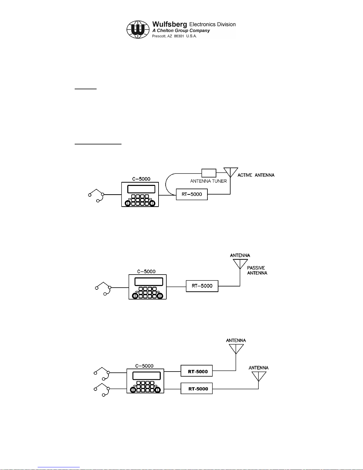
transceivers. System power requirements are included in Table 2-1. Figures 2-1 through 2- 6
show generalized system interface diagrams.
2. Sample Systems
The following are examples of ways to configure your aircraft installation:
Figure 2-1. Single RT-5000 with Active Antenna
Figure 2-2. Single RT-5000 with Passive Antenna
ACTIVE OR PASSIVE
ANTENNA
ACTIVE OR PASSIVE
ANTENNA
Figure 2-3. Dual RT-5000 with Dual Mic/Headset
Publication No. 150-041118 Page 2-1
Rev A Section 2 – System Installation
Sep 2001
C-5000 COMMUNICATION MANAGEMENT CONTROLLER
INSTALLATION MANUAL
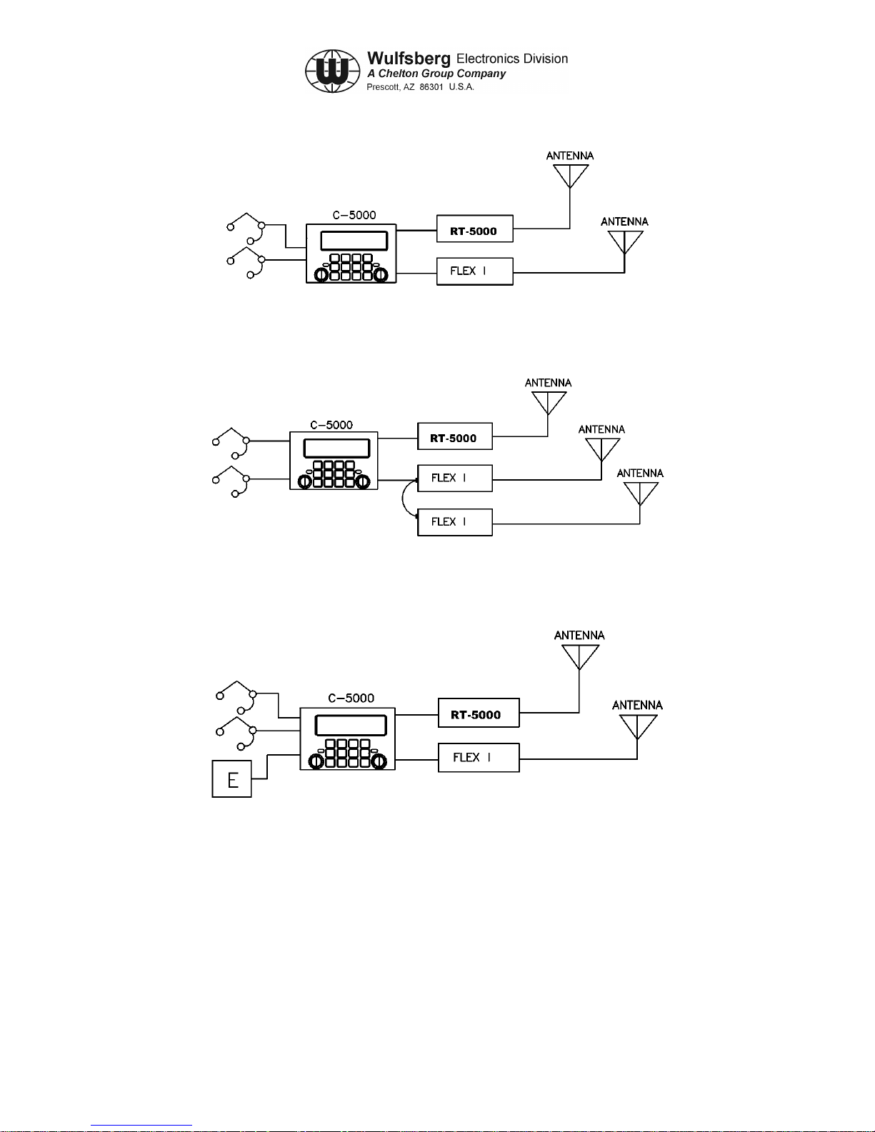
Figure 2-4. Dual Transceiver, RT-5000 and Flexcomm I
Figure 2-5. Dual Transceiver, RT-5000 and Parallel Flexcomm I Transceivers
Figure 2-6. Dual Transceiver with External Encryption
Page 2-2 Publication No. 150-041118
Section 2 – System Installation Rev A
Sep 2001

C-5000 COMMUNICATION MANAGEMENT CONTROLLER
INSTALLATION MANUAL
3. Component Specifications
COMPONENT POWER REQUIREMENTS
C-5000 VOLTAGE: 27.5 Vdc ± 20% Aircraft
CURRENT: 0.4 amps (typical)
1.3 amps (maximum external loading)
FLEXCOMM II
RT-5000
VOLTAGE: 27.5 VDC Aircraft
STANDBY: 1.7 amps
RECEIVE: 1.7 amps
TRANSMIT: 10.0 amps
FLEXCOMM I RT-30
RT-118
RT-138
Refer to FLEXCOMM I Transceiver System Installation
Manual, Manual Number 150-040011, for power
requirements.
RT-138F
RT-406F
RT-450
RT-9600
RT-9600F
RT-7200
Refer to VHF/FM Transceivers RT-7200, RT-9600,
AN/ARC-513(V) Installat ion /Oper at ors Manua l, Manual
Number 150-0061-000, for power requirements.
Table 2-1. System Power Requirements
A. C-5000 Communication Management Controller
Note: The installation and operation of the Frequency Agile C-5000 Control Unit is limited
to aircraft installations per FCC Rules and Regulations, Part 90, Section 90.423 and
90.203(h). A non-frequency agile C-5000 is available for other than aircraft
installations and is in compliance with FCC Rules and Regulations 90.203(g).
(1) Number of Channels: 350 programmable channels
(2) Temperature: -30° to + 60° C
(3) Panel Lighting: 5 Vdc, 5 Vac, or 28 Vdc
(4) Keypad Lighting: Type: Electro Luminescent (E.L.) Lighting
Publication No. 150-041118 Page 2-3
Rev A Section 2 – System Installation
Color: Blue/white (standard)
Green NVG (optional
Sep 2001

C-5000 COMMUNICATION MANAGEMENT CONTROLLER
INSTALLATION MANUAL
(5) Audio Output: Standard: 100 mV into 600 ohm load, shop adjustable
0.1 to 250 mW, 600 ohms
Unsquelched Audio: 0.5 VRMS/2k ohms, adjustable 0.1
to 1.5 V
(6) Audio Input Level: Std. Voice: 0.25 Vrms 150 ohm balanced pair, shop
adjustable 30 mV to 1.5 Vrms Narrowband: same as
voice, 2K single ended
(7) Microphone Interface: Carbon or equivalent
B. FLEXCOMM II (RT-5000)
(1) RT-5000 Transceiver
a) Tunability: 1.25 kHz Incremental Tuning Simplex/Semi-duplex.
b) Mode: FM/AM/P25/Trunking
c) Frequency Bands: 29.7-88 MHz (FM Band)
108-116 MHz (receive onl y)
118-156 MHz (AM Band)
138-174 MHz (FM Band)
220-225 MHz (AM/FM)
225-400 MHz (AM/FM)
FM:
403-512 MHz
512-806 MHz
806-960 MHz
d) Channeling: 12.5/20/25/30/50 kHz
e) Temperature: -30° C to + 60° C
f) Altitude: 51,000 feet above MSL
g) Control: C-5000 Serial Tuning Bus
h) Tx Power: 10 Watts FM/P25
15 Watts AM
Page 2-4 Publication No. 150-041118
Section 2 – System Installation Rev A
Sep 2001

C-5000 COMMUNICATION MANAGEMENT CONTROLLER
C. RT-5000 Antennas
1) AT-560 Antenna
1) Frequency: 29.7 - 960 MHz
2) VSWR: 2.5:1 maximum
3) Radiation Pattern: Omnidir ec t ion al in a zimuth
4) Polarization: Vertical
5) Impedance: 50 ohms
6) Power: 20 Watts
7) Gain: 30 MHz, -14 dBi
INSTALLATION MANUAL
88 MHz, -6 dBi
108-174 MHz, 0 dBi
220-960 MHz, 0 dBi
8) Temperature: -55°C to + 70°C
9) Altitude: 40,000 feet
2) AT-160 Antenna
1) Frequency: 29.7 - 960 MHz
2) VSWR: 2.5:1 maximum
3) Radiation Pattern: Omnidir ec t ion al in a zimuth
4) Polarization: Vertical
5) Impedance: 50 ohms
6) Power: 20 Watts
7) Gain: 30 MHz, -21 dBi
60 MHz, -21 dBi
88 MHz, -12 dBi
108-174 MHz, -3 dBi
225-960 MHz, 0 dBi
8) Temperature: -55°C to + 70°C
9) Altitude: 40,000 feet
3) AT-5000 Antenna
Publication No. 150-041118 Page 2-5
Rev A Section 2 – System Installation
Sep 2001

C-5000 COMMUNICATION MANAGEMENT CONTROLLER
INSTALLATION MANUAL
1) Frequency: 29.7 - 960 MHz
2) VSWR: 2.5:1 maximum
3) Radiation Pattern: Omnidir ec t ion al in a zimuth
4) Polarization: Vertical
5) Impedance: 50 ohms
6) Power: 20 Watts
7) Gain: 30 MHz, -15 dBi
88 MHz, -7.5 dBi
118-174 MHz, -3 dBi
225-960 MHz, 0 dBi
8) Temperature: -55°C to + 70°C
9) Altitude: 55,000 feet
4) AT-550 Antenna
1) Frequency: 29.7 - 960 MHz
2) VSWR: 2.5:1 maximum
3) Radiation Pattern: Omnidir ec t ion al in a zimuth
4) Polarization: Vertical
5) Impedance: 50 ohms
6) Power: 20 Watts
7) Gain: 30 MHz, -14 dBi
88 MHz, -6 dBi
108-174 MHz, 0 dBi
225-960 MHz, 0 dBi
8) Temperature: -55°C to + 70°C
9) Altitude: 40,000 feet
Page 2-6 Publication No. 150-041118
Section 2 – System Installation Rev A
Sep 2001

C-5000 COMMUNICATION MANAGEMENT CONTROLLER
INSTALLATION MANUAL
5) AT-50 Antenna
1) Frequency: 29.7 - 400 MHz
2) VSWR: 2: 1 maximum
3) Radiation Pattern: Omnidir ec t ion al in a zimuth
4) Polarization: Vertical
5) Impedance: 50 ohms
6) Power: 20 Watts
7) Gain: 30 MHz, -11 dBi
88 MHz, -6 dBi
108-174 MHz, 0 dBi
225-400 MHz, + 2 dBi
8) Temperature: -54°C to + 71°C
9) Altitude: 50,000 feet
6) AT-51 Antenna
1) Frequency: 29.7 - 400 MHz
2) VSWR: 2.5: 1 maximum
3) Radiation Pattern: Omnidir ec t ion al in a zimuth
4) Polarization: Vertical
5) Impedance: 50 Ohms
6) Power: 15 Watts
7) Gain: 30 MHz, -14 dBi
88 MHz, -7 dBi
108-174 MHz, -3 dBi
225-400 MHz, 0 dB
8) Temperature: -54°C to + 71°C
9) Altitude: 50,000 feet
Publication No. 150-041118 Page 2-7
Rev A Section 2 – System Installation
Sep 2001

C-5000 COMMUNICATION MANAGEMENT CONTROLLER
INSTALLATION MANUAL
7) AT-140 Antenna
1) Frequency: 29.7 - 400 MHz
2) VSWR: 2.5: 1 at 30-88 MHz
5.0: 1 at 108-117 MHz
2.5: 1 at 118-174 MHz
2.0: 1 at 225-400 MHz
3) Radiation Pattern: Omnidir ec t ion al in a zimuth
4) Polarization: Vertical
5) Impedance: 50 ohms
6) Power: 50 Watts
7) Gain: 30 MHz -22.5 dBi
88 MHz -10 dBi
108 - 174 MHz -2 dBi
225 - 400 MHz +2 dBi
8) Temperature: -54°C to + 71°C operating
-62°C to + 85°C non-operating
9) Altitude: 50,000 ft
8) AT-400 Antenna.
1) Frequency: 400 - 960 MHz
2) VSWR: 2.0: 1 maximum
3) Radiation Pattern: Typical of λ/4 stub
4) Polarization: Vertical
5) Impedance: 50 ohms
6) RF Power: 100 Watts
7) Efficiency: 90% min. 400 - 960 MHz
8) Temperature: -55°C to +70°C
9) Altitude: 50,000 ft
Page 2-8 Publication No. 150-041118
Section 2 – System Installation Rev A
Sep 2001
 Loading...