

Wuhan Huazhong Numerical Control Co., Ltd HNC-18xp/T, HNC-19iT v4.0, HNC-21T, HNC-22T, HNC-18iT Programming Manual
...Page 1

Century
Century
Century
Century Star
Star
Star
Star Turning
Turning
Turning
Turning CNC
CNC
CNC
CNC System
System
System
System
Programming
Programming
Programming
Programming Guide
Guide
Guide
Guide
V
V
V
V 3.3
November,
November,
November,
November, 2007
Wuhan
Wuhan
Wuhan
Wuhan Huazhong
© 2007 Wuhan Huazhong Numerical Control Co., Ltd
Huazhong
Huazhong
Huazhong Numerical
Numerical
Numerical
Numerical Control
3.3
3.3
3.3
2007
2007
2007
Control
Control
Control Co.,
Co.,
Co.,
Co., Ltd
Ltd
Ltd
Ltd
Page 2

Preface
Preface
Preface
Preface
Preface
Organization
Organization
Organization
Organization of
1. General
2. Preparatory Function
3. Interpolation Function
4. Feed Function
5. Coordinate System
6. Spindle Speed Function
7. Tool Function
8. Miscellaneous Function
9. Functions to Simplify Programming
10. Comprehensive Programming Example
11. Custom Macro
Applicability
Applicability
Applicability
Applicability
This Programming Guide is applicable to the following CNC system:
HNC-18iT/19iT v4.0
of
documentation
of
documentation
of documentation
documentation
HNC-18xp/T
HNC-19xp/T
HNC-21TD/22TD v05.62.07.10
Internet
Internet
Internet
Internet Address
http://www.huazhongcnc.com/
Address
Address
Address
i
Page 3

Table of Contents
Table
Table
Table
Table of
Preface ............................................................................................................................................. i
1 General ................................................................................................................................... 1
2 Preparatory Function (G code) ............................................................................................. 21
3 Interpolation Functions ......................................................................................................... 24
4 Feed Function ....................................................................................................................... 49
5 Coordinate System ................................................................................................................ 53
of
Contents
of
Contents
of Contents
Contents
1.1 CNC Programming ..................................................................................................... 2
1.2 Interpolation ................................................................................................................ 4
1.2.1 Linear Interpolation ........................................................................................ 4
1.2.2 Circular Interpolation ...................................................................................... 5
1.2.3 Thread Cutting ................................................................................................ 5
1.3 Feed Function ............................................................................................................. 6
1.4 Coordinate System ...................................................................................................... 7
1.4.1 Reference Point ............................................................................................... 7
1.4.2 Machine Coordinate System ........................................................................... 8
1.4.3 Workpiece Coordinate System ........................................................................ 9
1.4.4 Setting Two Coordinate Systems at the Same Position ................................ 10
1.4.5 Absolute Commands ..................................................................................... 11
1.4.6 Incremental Commands ................................................................................ 12
1.4.7 Diameter/Radius Programming .................................................................... 13
1.5 Spindle Speed Function ............................................................................................ 14
1.6 Tool Function ............................................................................................................ 15
1.6.1 Tool Selection ............................................................................................... 15
1.6.2 Tool Offset .................................................................................................... 15
1.7 Miscellaneous Function ............................................................................................ 18
1.8 Program Configuration ............................................................................................. 19
1.8.1 Structure of an NC Program ......................................................................... 19
1.8.2 Main Program and Subprogram .................................................................... 20
2.1 G code List ................................................................................................................ 22
3.1 Positioning (G00) ..................................................................................................... 25
3.2 Linear Interpolation (G01) ........................................................................................ 26
3.3 Circulation Interpolation (G02, G03) ....................................................................... 31
3.4 Chamfering and Rounding (G01, G02, G03) ............................................................ 37
3.4.1 Chamfering (G01) ......................................................................................... 37
3.4.2 Rounding (G01) ............................................................................................ 38
3.4.3 Chamfering (G02, G03) ................................................................................ 40
3.4.4 Rounding (G02, G03) ................................................................................... 41
3.5 Thread Cutting with Constant Lead (G32) ............................................................... 43
3.6 Tapping (G34) ........................................................................................................... 46
4.1 Rapid Traverse (G00) ............................................................................................... 50
4.2 Cutting Feed (G94, G95) .......................................................................................... 51
4.3 Dwell (G04) .............................................................................................................. 52
5.1 Reference Position Return (G28) .............................................................................. 54
5.2 Auto Return from Reference Position (G29) ............................................................ 55
5.3 Setting a Workpiece Coordinate System (G92) ........................................................ 57
5.4 Selecting a Machine Cooridinate System (G53) ....................................................... 58
5.5 Selecting a Workpiece Coordinate System (G54~G59) ............................................ 59
5.6 Origin of a Workpiece Coordinate System (G51, G50) ............................................ 61
5.7 Absolute and Incremental Programming (G90, G91) ............................................... 62
ii
Page 4

Table of Contents
5.8 Diameter and Radius Programming (G36, G37) ...................................................... 64
5.9 Inch/Metric Conversion (G20, G21) ......................................................................... 66
6 Spindle Speed Function ........................................................................................................ 67
6.1 Limit of Spindle Speed (G46) ................................................................................... 68
6.2 Constant Surface Speed Control (G96, G97) ............................................................ 69
7 Tool Function ........................................................................................................................ 71
7.1 Tool Selection and Tool Offset (T code) ................................................................... 72
7.2 Tool Radius Compensation (G40, G41, G42) ........................................................... 74
8 Miscellaneous Function ........................................................................................................ 76
8.1 M code List ............................................................................................................... 77
8.2 CNC M-Function ...................................................................................................... 78
8.2.1 Program Stop (M00) ..................................................................................... 78
8.2.2 Optional Stop (M01) ..................................................................................... 78
8.2.3 End of Program (M02) .................................................................................. 78
8.2.4 End of Program with return to the beginning of program (M30) ................. 78
8.2.5 Subprogram Control (M98, M99) ................................................................. 79
8.3 PLC M Function ....................................................................................................... 81
8.3.1 Spindle Control (M03, M04, M05) ............................................................... 81
8.3.2 Coolant Control (M07, M08, M09) .............................................................. 81
9 Functions to Simplify Programming .................................................................................... 82
9.1 Canned Cycles .......................................................................................................... 83
9.1.1 Internal Diameter/Outer Diameter Cutting Cycle (G80) .............................. 83
9.1.2 End Face Turning Cycle (G81) ..................................................................... 88
9.1.3 Thread Cutting Cycle (G82) ......................................................................... 91
9.1.4 End Face Peck Drilling Cycle (G74) ............................................................ 94
9.1.5 Outer Diameter Grooving Cycle (G75) ........................................................ 96
9.2 Multiple Repetitive Cycle ......................................................................................... 98
9.2.1 Stock Removal in Turning (G71) .................................................................. 98
9.2.2 Stock Removal in Facing (G72) ................................................................. 104
9.2.3 Pattern Repeating (G73) ............................................................................. 108
9.2.4 Multiple Thread Cutting Cycle (G76) ......................................................... 111
10 Comprehensive Programming .................................................................................... 114
10.1 Example 1 ............................................................................................................... 114
10.2 Example 2 ............................................................................................................... 116
10.3 Example 3 ............................................................................................................... 118
10.4 Example 4 ............................................................................................................... 119
11 Custom Macro .................................................................................................................... 120
11.1 V ariables ................................................................................................................. 121
11.1.1 Type of Variables ........................................................................................ 121
11.1.2 System Variables ........................................................................................ 122
11.2 Constant .................................................................................................................. 129
11.3 Operators and Expression ....................................................................................... 130
11.4 Assignment ............................................................................................................. 131
11.5 Selection statement
IF,
ELSE,ENDIF ..................................................................... 132
11.6 Repetition Statement WHILE, ENDW ................................................................... 133
11.7 Macro Call .............................................................................................................. 134
11.8 Example .................................................................................................................. 136
iii
Page 5

1. General
1
General
1
General
1
1 General
General
This chapter is to introduce the basic concepts in Computerized Numerical Control (CNC)
system: HNC-21T /22
T,
HNC-18iT/19iT, HNC-18xp/
T
, HNC-19xp/
T
.
1
Page 6

1.1
CNC
1.1
CNC
1.1
1.1 CNC
CNC Programming
To
operate CNC machine tool, the first step is to understand the part drawing and produce a
program manual script. The procedure for machining a part is as follows (Figure 1.1):
1) Read drawing
2) Produce the program manual script
3) Input the program manual script by using the machine control panel
4) Manufacture a part
Programming
Programming
Programming
1. General
2
Page 7
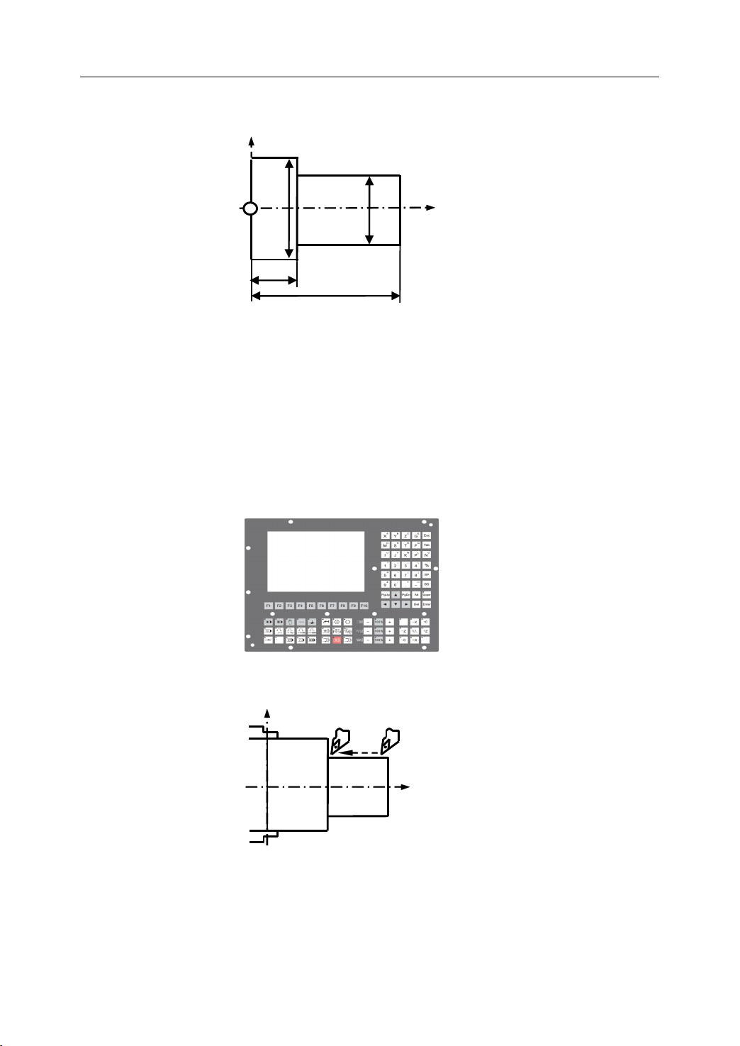
1. Read drawing
X
1. General
Φ60
Φ40
4 0
1 50
2. Produce the program manual script
N1 T0106
N2 M03 S460
N3 G00 X90Z20
N4 G00 X31Z3
N5 G01 Z-50 F100
N6 G00 X36
N7 Z3
…
3. Input the program manual script
Ζ
4. Manufacture a part
X
Z
Figure 1 . 1 The workflow of operation of CNC machine tool
3
Page 8
1. General
X
Z
X
Z
1.2
Interpolation
1.2
Interpolation
1.2
1.2 Interpolation
Interpolation
Interpolation refers to an operation in which the machine tool moves along the workpiece
parts. There are five methods of interpolation: linear, circular, helical, parabolic, and cubic.
Most CNC machine can provide linear interpolation and circular interpolation. The other
three methods of interpolation (helical, parabolic, and cubic interpolation) are usually used
to manufacture the complex shapes, such as aerospace parts. In this manual, linear and
circular interpolation are introduced.
1.2.1
1.2.1
1.2.1
1.2.1 L
There are two kinds of linear interpolation:
L
inear
L
inear
L inear
inear Interpolation
1) Tool movement along a straight line (Figure 1.2).
2) Tool movement along the taper line
Interpolation
Interpolation
Interpolation
Figure 1 . 2 Linear Interpolation (1)
Figure 1 . 3 Linear Interpolation (2)
4
Page 9
1. General
X
Z
1.2.2
1.2.2
1.2.2
1.2.2 Circular
Figure 1.4 shows a tool movement along an arc.
Note:
Note:
Note:
Note:
In this manual, it is assumed that tools are moved against workpieces.
Circular
Circular
Circular Interpolation
Interpolation
Interpolation
Interpolation
Figure 1 . 4 Circular Interpolation
1.2.3
1.2.3
1.2.3
1.2.3 Thread
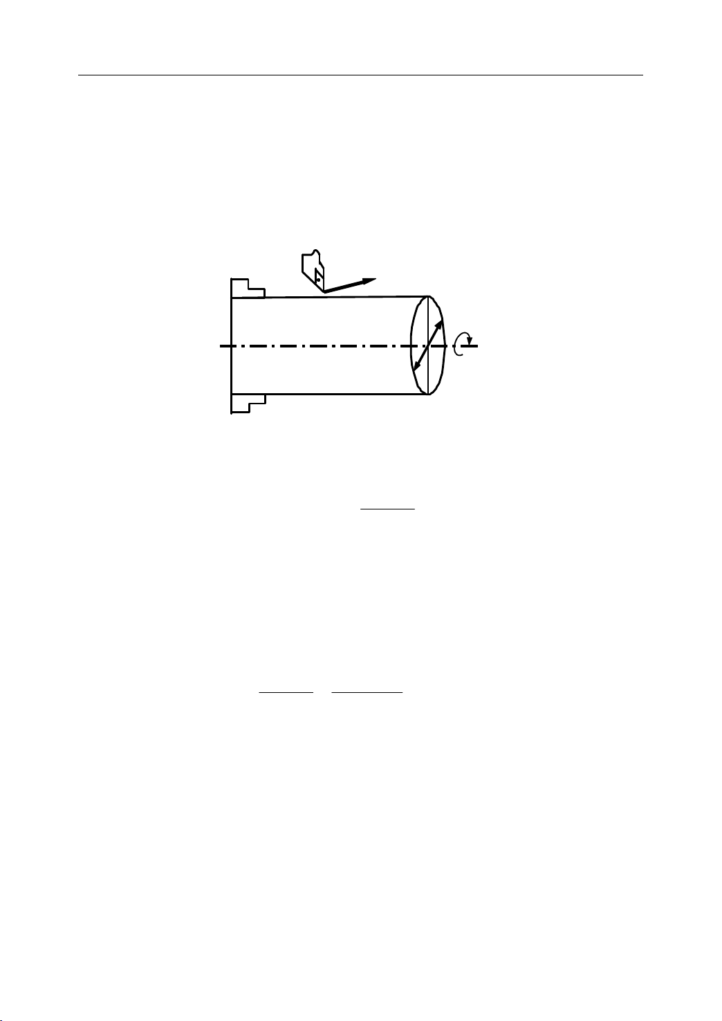
There are several kinds of threads: c ylindrical, taper or face threads .
workpiece, the tool is moved with spindle rotation synchronously .
Thread
Thread
Thread Cutting
Cutting
Cutting
Cutting
Figure 1 . 5 Thread Cutting
To
cut threads on a
5
Page 10
1. General
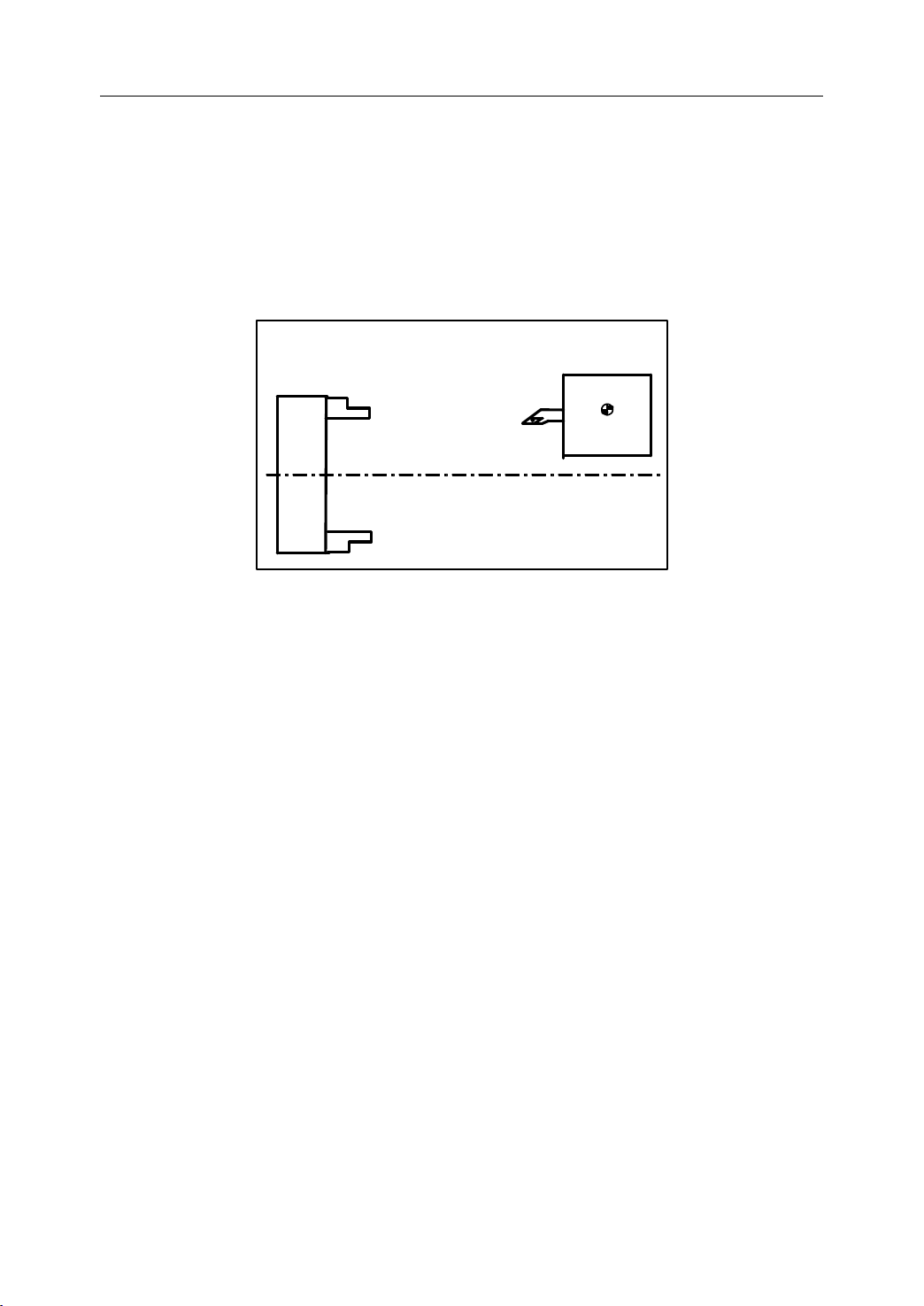
Tool
Chuck
1.3
Feed
1.3
Feed
1.3
1.3 Feed
Feed Function
- Feed refers to an operation in which the tool moves at a specified speed to cut a
workpiece.
- Feedrate refers to a specified speed, and numeric is used to specified the fe e drate .
- Feed function refers to an operation to control the fe e drate .
Function
Function
Function
Figure 1 . 6 Feed Function
For example:
F2.0 //feed the tool 2mm, while the workpiece makes one turn
6
Page 11
1.4
Reference
position
Tool post
Chuck
Coordinate
1.4
Coordinate
1.4
1.4 Coordinate
Coordinate System
System
System
System
1. General
1.4.1
1.4.1
1.4.1
1.4.1 Reference
Reference point is a fixed position on CNC machine tool, which is determined by cams and
measuring system. Generally, it is used when the tool is required to exchange or the
coordinate system is required to set.
There are two ways to move to the reference point:
Reference
Reference
Reference Point
Point
Point
Point
Figure 1 . 7 Reference Point
- Manual reference position return: The tool is moved to the reference point by operating
the button on the machine control panel. It is only used when the machine is turned on.
- Automatic reference position return: It is used after the manual reference position return
has been used. In this manual, this would be introduced.
7
Page 12
1. General
+
X
+
X
+
Y
'
+Z+
Y
+
Z
+Y+
C
+
Z
'
+A +
B
+
C
+ X +Y +
Z
+
A
+
B
+
X
'
1.4.2
1.4.2
1.4.2
1.4.2 Machine
Machine
Machine
Machine Coordinate
Coordinate
Coordinate
Coordinate System
System
System
System
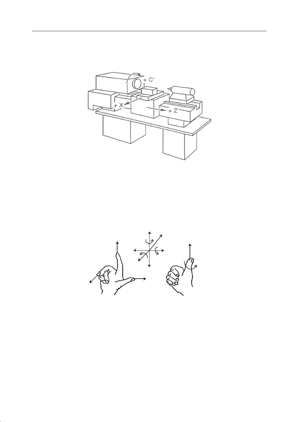
The coordinate system is set on a CNC machine tool. Figure 1.8 is a machine coordinate
system of turning machine, and shows the direction of axes:
Figure 1 . 8 Machine Coordinate System
In general , three basic linear coordinate axes of motion are X,
Y,
Z. Moreover, X,
Y,
Z axis
of rotation is named as A, B, C cor respond ently. Due to different types of turning machine,
the axis direction can be decided by following the rule – “ three finger rule ” of the right
hand.
Figure 1 . 9 “ three finger rule ”
- The thumb points the X axis. X axis controls the cross motion of the cutting tool.
“ +X ” means that the tool is away from the spindle centerline
- T he index points the Y axis. Y axis is usually a virtual axis.
- T he middle finger points the Z axis. Z axis controls the motion of the cutting tool.
“ +Z ” means that the tool is away from the spindle.
8
Page 13

1. General
1.4.3
1.4.3
1.4.3
1.4.3 Workpiece
The coordinate system is set on a workpiece. The data in the NC program is from the
workpiece coordinate system.
Example: Those four points can be defined on workpiece coordinate system:
Workpiece
Workpiece
Workpiece Coordinate
Coordinate
Coordinate
Coordinate System
Z-
X-
Figure 1 . 10 Workpiece Coordinate System
System
System
System
Y+
W
W
W
W
Y-
X+
90 °
90 °
90 °
Z+
P1 corresponds to X25 Z-7.5
P2 corresponds to X40 Z-15
P3 corresponds to X40 Z-25
P4 corresponds to X60 Z-35
P4
P3
25
35
Figure 1 .11Example of defining points on workpiece coordinate system
X
P2
P1
7.5
15
Φ 60
Φ 40
Φ 25
Z
9
Page 14
1. General
4 0
Ζ
Φ60
Φ40
1 50
X
Ζ
X
3 0
Ζ
Φ60
Φ30
8 0
X
10 0
Ζ
X
1.4.4
1.4.4
1.4.4
1.4.4 Setting
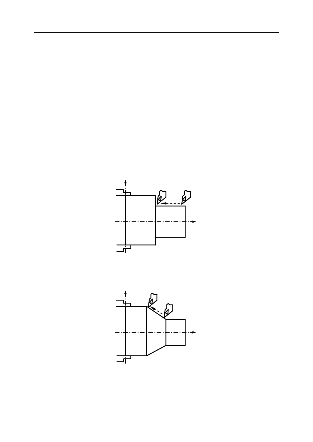
There are two methods used to define two coordinate systems at the same position.
Setting
Setting
Setting Two
1) The coordinate zero point is set at chuck face
2) The coordinate zero point is set at the end face of workpiece
Two
Coordinate
Two
Coordinate
Two Coordinate
Coordinate Systems
Figure 1 . 12 The coordinate zero point set at chuck face
Systems
Systems
Systems at
at
the
at
the
at the
the Same
Same
Same
Same Position
Position
Position
Position
Figure 1 . 13 The coordinate zero point set at the end face of workpiece
10
Page 15

1. General
1.4.5
1.4.5
1.4.5
1.4.5 Absolute
The absolute dimension describes a point at “ the distance from zero point of the coordinate
system ” .
E xample: These four point in absolute dimensions are the following:
Absolute
Absolute
Absolute Commands
P1 corresponds to X25 Z-7.5
P2 corresponds to X40 Z-15
P3 corresponds to X40 Z-25
P4 corresponds to X60 Z-35
Commands
Commands
Commands
P4
P3
25
35
X
P2
P1
7.5
15
Φ 60
Φ 40
Φ 25
Z
Figure 1 . 14 Absolute Dimension
11
Page 16
1. General
1.4.6
1.4.6
1.4.6
1.4.6 Incremental
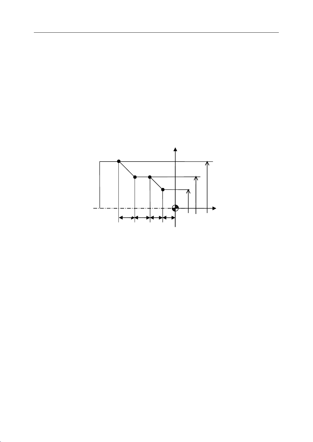
The incremental dimension describes a distance from the previous tool position to the next
tool position.
Example: These four point in incremental dimensions are the following:
Incremental
Incremental
Incremental Commands
P1 corresponds to X25 Z-7.5 //with reference to the zero point
P2 corresponds to X15 Z-7.5 //with reference to P1
P3 corresponds to Z-10 //with reference to P2
P4 corresponds to X20 Z-10 //with reference to P3
Commands
Commands
Commands
P4
10
X
P2
P3
P1
7.5
7.5
10
Φ 60
Φ 40
Φ 25
Z
Figure 1 . 15 Incremental Dimension
12
Page 17
1. General
8
8
8
8 0
0
0
0
6
6
6
6 0
0
0
0
B
B
B
B
A
A
A
A
Φ40
X
X
X
X
Z
Z
Z
Z
Φ30
8
8
8
8 0
0
0
0
6
6
6
6 0
0
0
0
B
B
B
B
A
A
A
A
20
X
X
X
X
Z
Z
Z
Z
15
1.4.7
1.4.7
1.4.7
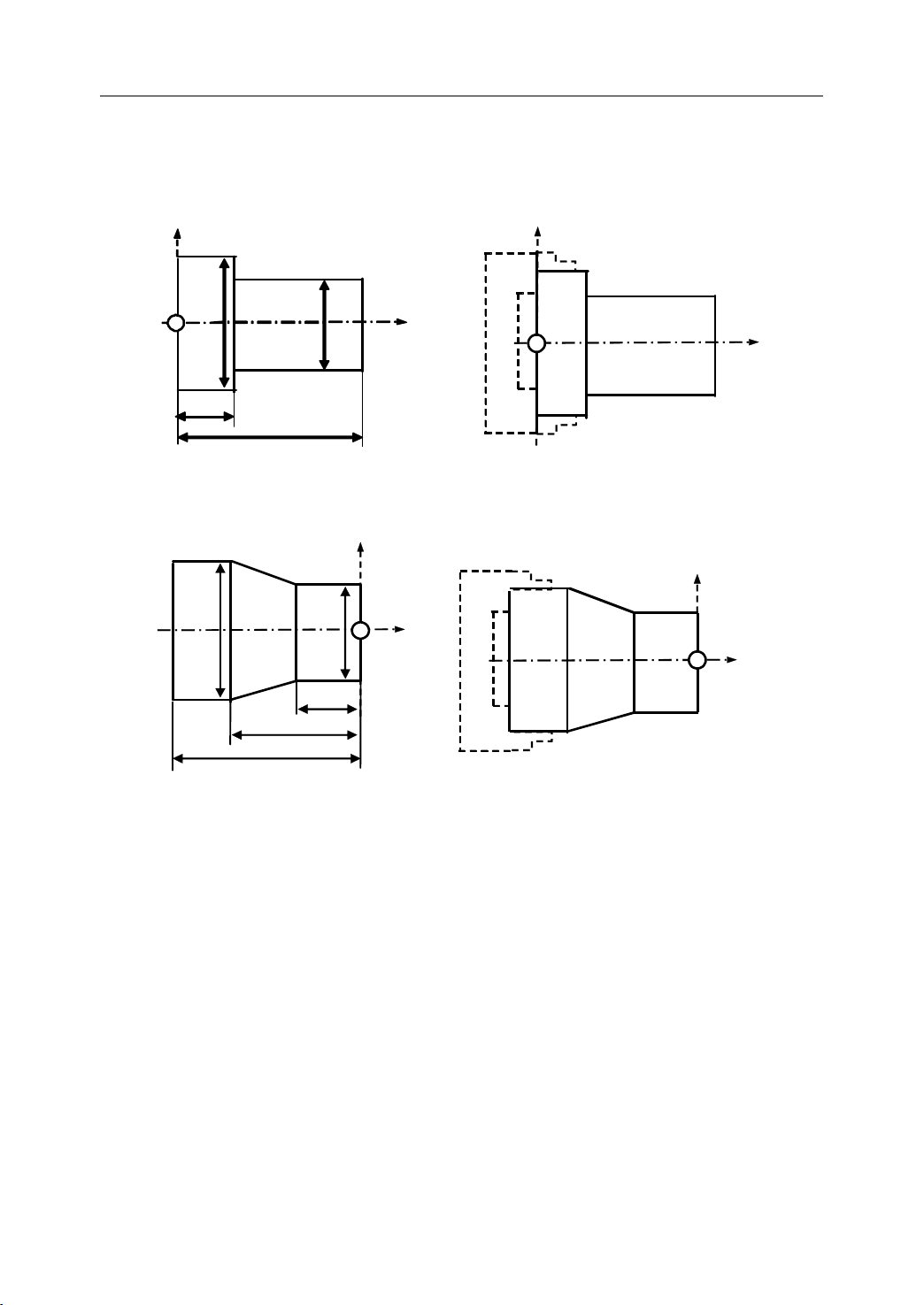
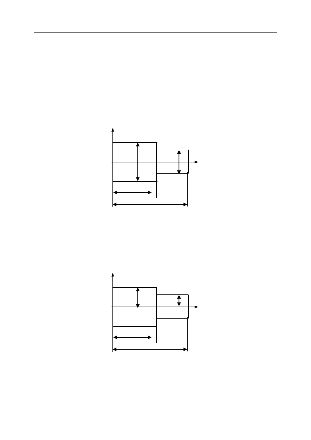
1.4.7 Diameter/Radius
Diameter/Radius
Diameter/Radius
Diameter/Radius Programming
Programming
Programming
Programming
The coordinate dimension on X axis can be set in diameter or radius. It should be noted that
diameter programming or radius programming should be applied independently on each
machine.
Example: Describe the points by diameter programming.
A
corresponds to X30 Z80
B corresponds to X40 Z60
Figure 1 . 16 Diameter Programming
Example: Describe the points by radius programming.
A
corresponds to X15 Z80
B corresponds to X20 Z60
Figure 1 . 17 Radius Programming
13
Page 18
1. General
N
·
min
-
1
Chuck
V: Cutting speed
v m/min
1.5
Spindle
1.5
Spindle
1.5
1.5 Spindle
Spindle Speed
The cutting speed (v) refers to the speed of the tool with respect to the workpiece when the
workpiece is cut. The unit of the cutting speed is m/min. As for the CNC, the cutting speed
can be specified by the spindle speed (N) in min-1.
Speed
Speed
Speed Function
Figure 1 . 18 Cutting Speed and Spindle Speed
Function
Function
Function
The formula to get the spindle speed is:
N: the spindle speed
v: cutting speed
D: diameter value of the workpiece
Example: When the diameter of workpiece is 200mm, and the cutting speed is 300m/min,
v
then the spindle speed:
N
=
∗
=
D
The constant surface speed refers to the cutting speed even when the workpiece diameter is
changed, and the CNC changes the spindle speed.
1000
N
=
D
π
30010001000
∗
≈
200
∗
ππ
mr
/478
v
∗
14
Page 19
1.6
Tool
1.6
Tool
1.6
1.6 Tool
Tool Function
Function
Function
Function
1. General
1.6.1
1.6.1
1.6.1
1.6.1 Tool
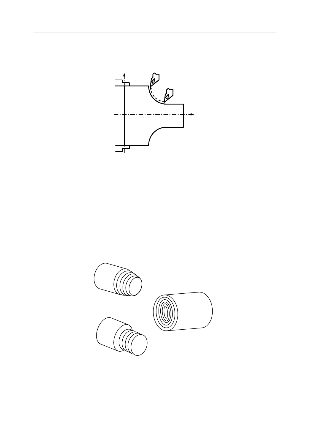
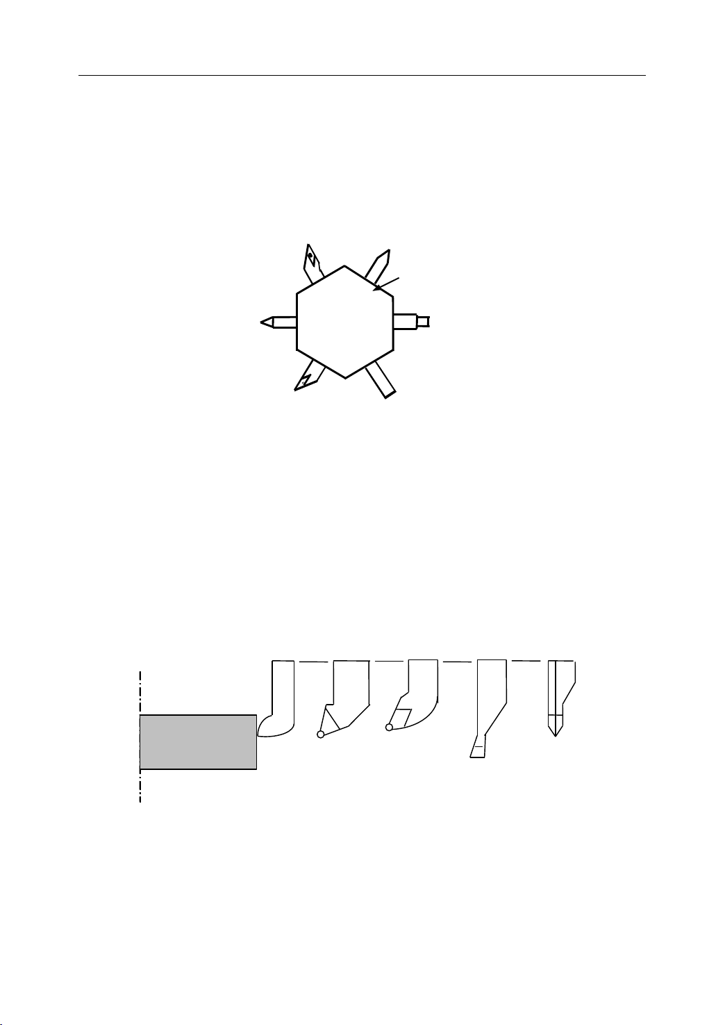
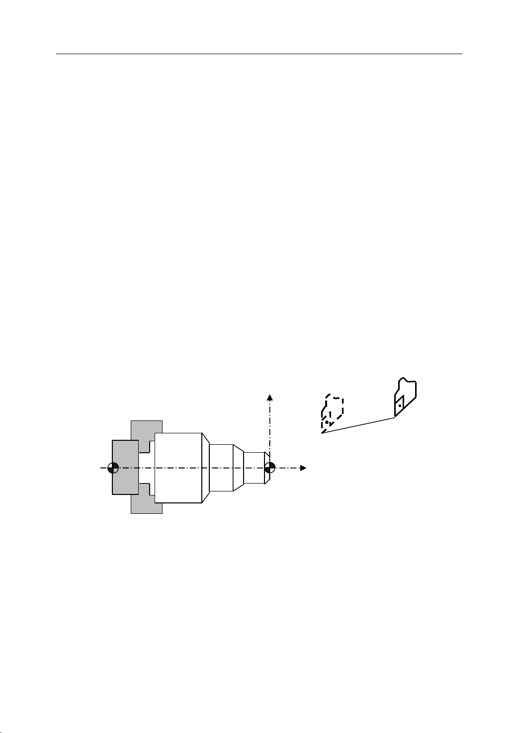
It is necessary to select a suitable tool when drilling, tapping, boring or the like is performed.
As it is shown in Figure 1.19, a number is assigned to each tool. Then this number is used in
the program to specify that the corresponding tool is selected.
1.6.2
1.6.2
1.6.2
1.6.2 Tool
When writing a program, the operator just use the workpiece dimensions according to the
dimensions in the part drawing. The tool nose radius center , the tool direction of the turning
Tool
Selection
Tool
Selection
Tool Selection
Selection
Tool
Offset
Tool
Offset
Tool Offset
Offset
01
02
03
Figure 1 . 19
06
04
Tool
05
Selection
Tool
number
Tool
number
Tool
Tool number
number
Tool
post
Tool
post
Tool
Tool post
post
tool, and the tool length are not taken into account. However, when machining a workpiece,
the tool path is affected by the tool geometry.
workpiece
workpiece
workpiece
workpiece
Standard
tool
Rough
cutting
tool
Figure 1 . 20
Finishing
tool
Tool
Offset
15
Grooving
tool
Thread
cutting
tool
Page 20
1. General
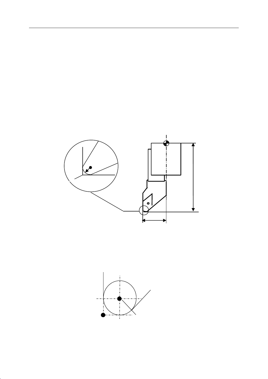
T
ool nose radius center
P
Imaginary tool
nose
� Tool Length Compensation
There are two kind of ways to specify the value of tool length compensation.
- Absolute value of tool length compensation (the distance between tool tip and
machine reference point)
- Incremental value of tool length compensation (the distance between tool tip and
the standard tool)
As it is shown in Figure 1.21, L1 is the tool length on X axis. L2 is the tool length on Z axis.
It should be noted that the tool wear values on X axis or Z axis are also contained in the tool
length compensation.
R
S
P
P=Tool
P=Tool
P=Tool
P=Tool tip
R=Radius
R=Radius
R=Radius
R=Radius
S=Cutting
S=Cutting
S=Cutting
S=Cutting edge
tip
tip
tip
Figure 1 . 21
edge
center
edge
center
edge center
center
Tool
Length Compensation
L2
L1
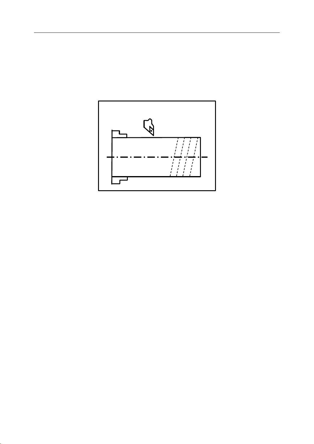
� Tool Radius Compensation
Figure 1.22 shows the imaginary tool nose as a start position when writing a program.
Figure 1 . 22 The imaginary tool nose
16
Page 21
1. General
7
●
X
X
X
X
0 9
Z
Z
Z
Z
●
●
●
●
●
●
●
●
8
3
4
5
6
2
1
● Imaginary tool nose
+
+
+
+ T o ol nose radius center
7
●
X
X
X
X
0 9
Z
Z
Z
Z
●
●
●
●
●
●
●
●
5
6
8
2
3
4
1
● Imaginary tool nose
+
+
+
+ Tool nose radius center
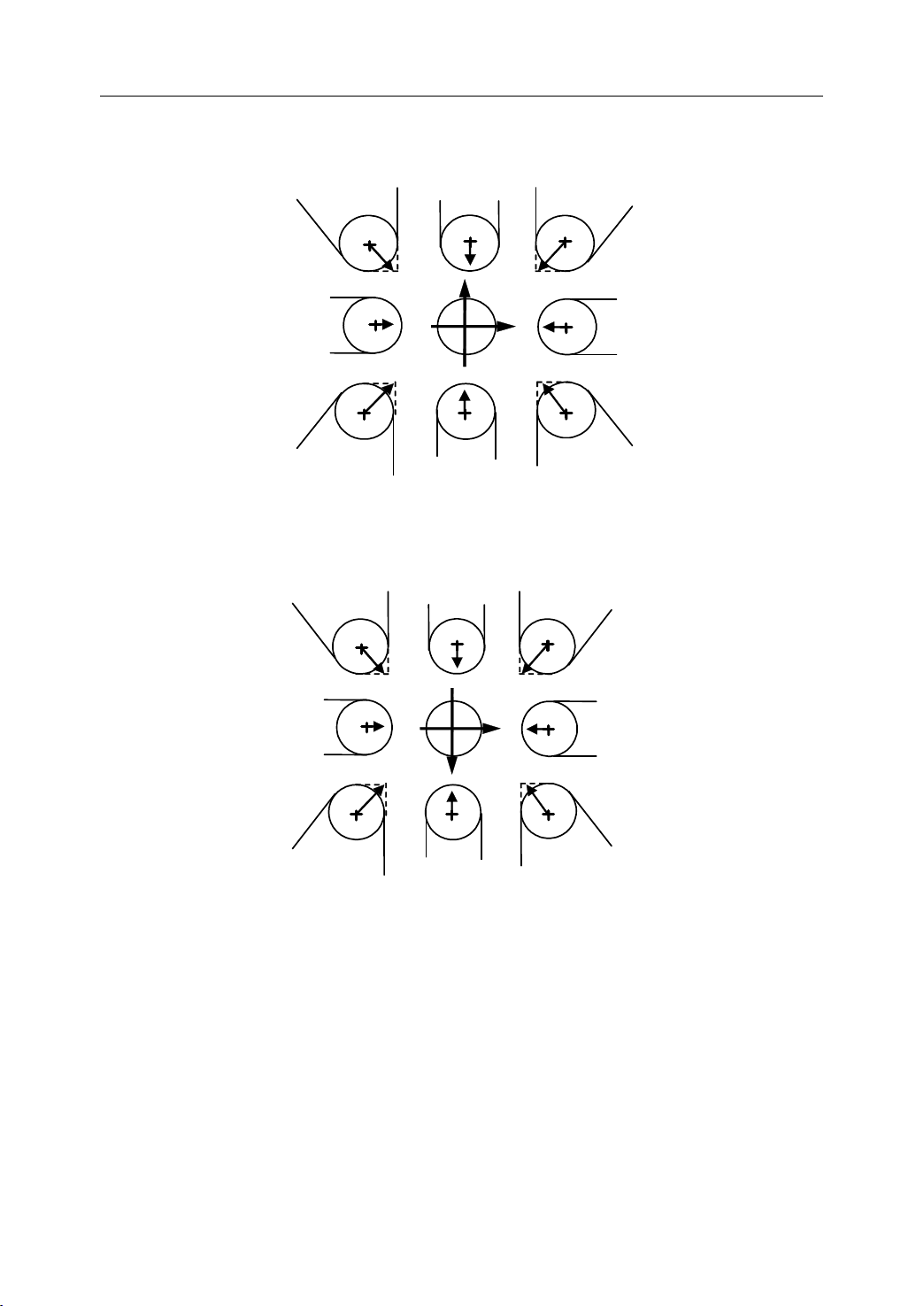
The direction of imaginary tool nose is determined by the tool direction during cutting.
Figure 1.23 and Figure 1.24 show the relation between the tool and the imaginary tool tip.
Figure 1 . 23 The direction of imaginary tool nose (1)
Figure 1 . 24 The direction of imaginary tool nose (2)
17
Page 22

1. General
1.7
Miscellaneous
1.7
Miscellaneous
1.7
1.7 Miscellaneous
Miscellaneous Function
Miscellaneous function refers to the operation to control the spindle, feed, and coolant. In
general, it is specified by an M code.
When a move command and M code are specified in the same block, there are two ways to
execute these commands:
1) Pre-M function
M command is executed before the completion of move command
2) Post-M function
M command is executed after the completion of move command.
The sequence of the execution depends on the specification of the machine tool builder.
Function
Function
Function
18
Page 23

1. General
%1000
N01 G91 G00 X50 Y60
N10 G01 X100 Y500 F150 S300 M03
N...... ;COMMENT
N200 M30
Program
Program block
Command character
Program number
N.. G .. X … Y … F.. M.. S..
Program block
Miscellaneous function
Spindle function
Feed Function
Coordinate - Dimension word
Preparatory function
Program block number
Program
1.8
Program
1.8
Program
Program Configuration
1.8
1.8
1.8.1
1.8.1
1.8.1
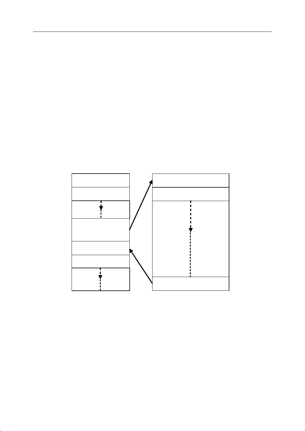
1.8.1 Structure
As it is shown in Figure 1.25, an NC program consists of a sequence of NC blocks
block is one of machining steps. Commands
Structure
Structure
Structure of
- Format of program
Configuration
Configuration
Configuration
of
an
of
of an
program
program
program name
NC
an
NC
an NC
NC Program
Commands
Commands
Commands in each block are the instruction.
Figure 1 . 25 Structure of an NC Program
name
name
name
Program
Program
Program
blocks
blocks
blocks . Each
The program name must be specified in the format OXXXX (X could be letters or
numbers).
program
- Format of program
T he program number should be started with %XXXX or OXXXX (X could be numbers
only).
- Format of blocks
A
block starts with the program block number.
program
program number
blocks
blocks
blocks
number
number
number
Figure 1 . 26 Structure of Block
19
Page 24
end
Instruction 1
Instruction 2
Instruction n
Instruction n+1
Follow the direction
ofthe subprogra m
Instruction 1
Instruction 2
Return to the main pr ogram
Main program
Subprogram
of
- Format of end
The last block should contain M02 or M03 to indicate the end of program.
- Format of Comments
All information after the “ ; ” is regarded as comments.
All information between “ ( ) ” is regarded as comments.
end
end of
Comments
Comments
Comments
program
of
program
of program
program
1. General
1.8.2
1.8.2
1.8.2
1.8.2 Main
There are two type of program: main program and subprogram. The CNC operates
according to the main program. When a execution command of subprogram is at the
execution line of the main program, the subprogram is called. When the execution of
subprogram is finished, the system returns control to the main program.
Main
Main
Main Program
Program
Program
Program and
and
Subprogram
and
Subprogram
and Subprogram
Subprogram
Note:
Note:
Note:
Note:
Main program and its subprogram must be written in a same file with a different program
codes.
Figure 1 . 27 Main program and subprogram
20
Page 25

2
Preparatory
2
Preparatory
2
2 Preparatory
Preparatory Function
There are two types of G code: one-shot G code, and modal G code.
Type
Type
Type
Type Meaning
One-shot G code The G code is only effective in the block in which it is specified
Modal G code The G code is effective until another G code is specified.
Example : G01 and G00 are modal G codes.
G00X_
Meaning
Meaning
Meaning
Function
Function
Function (G
Table 2 1 Type of G code
(G
(G
(G code)
code)
code)
code)
2. Preparatory Function
G01Z_
Z_
X_
G0 0 is effective in this range
21
Page 26

2.1
G
2.1
2.1
2.1 G
The following table is the list of G code in HNC system.
code
G
code
G code
code List
G
code
G
code
G
G code
code Group
List
List
List
Group
Group
Group Function
Function
Function
Function
Table 2 2 G code list
2. Preparatory Function
G00
G01
◣
01
G02
G03
G04 00 Dwell
G20
G21
◣
G28
G29
G32
G34
G36
◣
G37
G40
◣
G41
08
00
01
17
09
Positioning (Rapid traverse)
Linear interpolation (Cutting feed)
Circular interpolation CW
Circular interpolation CCW
Input in inch
Input in mm
R eference point return
Auto r eturn from reference point
Thread cutting with constant lead
Tapping
Diameter programming
Radius programming
Tool nose radius compensation cancel
Tool nose radius compensation on the left
G42
G46 16 Setting the limit of spindle speed
◣ G50
04
G51 Moving the origin of workpiece coordinate system
G53 00 Selecting a machine coordinate system
G54
◣
G55
G56
G57
G58
11 Setting a w orkpiece coordinate system
Tool nose radius compensation on the right
C anceling the workpiece’s origin movement
22
Page 27

2. Preparatory Function
G59
23
Page 28

2. Preparatory Function
G71
G72
Stock Removal in Turning
Stock Removal in Facing
G73
G74
G75
06
G76
G80
G81
G82
G90
◣
Pattern repeating
Front drilling cycle
Side drilling cycle
Multiple t hread cutting cycle
Internal diameter/ Outer diameter cutting cycle
End face turning cycle
Thread cutting cycle
Absolute programming
13
G91
Incremental programming
G92 00 Setting a c oordinate system
◣ G94
Feedrate per minute
14
G95
G96
Feedrate p er revolution
Constant cutting speed
16
Constant cutting speed cancel◣ G97
Explanation:
Explanation:
Explanation:
Explanation:
1) G codes in 00 group are one-shot G code, while the other groups are modal G
code.
2) ◣ means that it is default setting.
24
Page 29

3
Interpolation
3
Interpolation
3
3 Interpolation
Interpolation Functions
This chapter would introduce:
1) Positioning Command (G00)
2) Linear Interpolation (G01)
3) Circular Interpolation (G02, G03)
4) Chamfering and Rounding (G01, G02, G03)
5) Thread Cutting with Constant Lead (G32)
6) Tapping (G34)
Functions
Functions
Functions
3. Interpolation Function
25
Page 30
3.1
Positioning
3.1
Positioning
3.1
3.1 Positioning
Positioning (G00)
Programming
Programming
Programming
Programming
G00 X(U) … Z(W) …
(G00)
(G00)
(G00)
3. Interpolation Function
Explanation
Explanation
Explanation
Explanation of
X, Z Coordinate value of the end point in the absolute command
U, W Coordinate value of the end point in the incremental command
Function
Function
Function
Function
The tool is moved at the highest possible speed (rapid traverse). I f the rapid traverse
movement is required to execute simultaneously on several axes, the rapid traverse speed is
decided by the axis which takes the most time. The operator can use this function to position
the tool rapidly, to travel around the workpiece, or to approach the tool change position.
Example
Example
Example
Example
Move tool from P1 (45, 90) to P2 (10, 20) at the rapid traverse speed.
of
the
parameters
of
the
of the
parameters
the parameters
parameters
X
X
X
X
P1
P1
P1
P1
P2
P2
P2
P2
M
M
M
M
Absolute programming:
G00 X10 Z20
Incremental programming:
G00 U30 W70
W
W
W
W
Figure 3 . 1 Positioning (Rapid Traverse)
26
Z
Z
Z
Z
Page 31

3.2
Linear
3.2
Linear
3.2
3.2 Linear
Linear Interpolation
Programming
Programming
Programming
Programming
G01 X(U) … Z(W) … F …
Interpolation
Interpolation
Interpolation (G01)
(G01)
(G01)
(G01)
3. Interpolation Function
Explanation
Explanation
Explanation
Explanation of
X, Z Coordinate value of the end point in the absolute command
U, W Coordinate value of the end point in the incremental command
F Feedrate. It is effective until a new value is specified.
Function
Function
Function
Function
The tool is moved along the straight line at the specified fe e drate .
of
the
parameters
of
the
of the
parameters
the parameters
parameters
27
Page 32

3. Interpolation Function
Example
Example
Example
Example 1
1
1
1
Use G01 command to rough machining and finish machining the simple cylinder part .
%3306
Absolute command
(
N1 T0106
N2 M03 S460
N3 G00 X90Z20
N4 G00 X31Z3
N5 G01 Z-50 F100
N6 G00 X36
N7 Z3
Φ30
50
Figure 3 . 2 Linear Interpolation – Example 1
)
%3306
Φ35
Incremental command
(
N1 T0101
N2 M03 S460
N3 G00 X90Z20
N4 G00 X31Z3
N5 G01 W-53 F100
N6 G00 U5
N7 W53
)
N8 X30
N9 G01 Z-50 F80
N10 G00 X36
N11 X90 Z20
N12 M05
N13 M30
N8 U-6
N9 G01 Z-50 F80
N10 G00 X36
N11 X90 Z20
N12 M05
N13 M30
28
Page 33

3. Interpolation Function
Example
Example
Example
Example 2
2
2
2
Use G01 command to rough machining and finish machining simple conical part.
%3307
N1 T0101
N2 M03 S460
N3 G00 X100Z40
N4 G00 X26.6 Z5
N5 G01 X31 Z-50 F100
N6 G00 X36
N7 X100 Z40
N8 T0202
Φ30
Figure 3 . 3 Linear Interpolation – Example 2
Φ26
Φ35
50
N9 G00 X25.6 Z5
N10 G01 X30 Z-50 F80
N11 G00 X36
N12 X100 Z40
N13 M05
N14 M30
29
Page 34

3. Interpolation Function
Example
Example
Example
Example 3
3
3
3
Use G01 command to rough machining and finish machining the part.
2 × 4 5 °
Φ30
Figure 3 . 4 Linear Interpolation – Example 3
Φ28
Φ24
20
50
Φ35
%3308
N1 T0101
N2 M03 S450
N3 G00 X100 Z40
N4 G00 X31 Z3
N5 G01 Z-50 F100
N6 G00 X36
N7 Z3
N8 X25
N9 G01 Z-20 F100
N10 G00 X36
N11 Z3
N12 X15
N13 G01 U14 W-7 F100
N14 G00 X36
30
Page 35

N15 X100 Z40
N16 T0202
N17 G00 X100Z40
N18 G00 X14 Z3
N19 G01 X24 Z-2 F80
N20 Z-20
N21 X28
N22 X30 Z-50
N23 G00 X36
N24 X80 Z10
N24 M05
3. Interpolation Function
N25 M30
31
Page 36

3.3
Circulation
3.3
Circulation
3.3
3.3 Circulation
Circulation Interpolation
Programming
Programming
Programming
Programming
Interpolation
Interpolation
Interpolation (G02,
(G02,
(G02,
(G02, G03)
G03)
G03)
G03)
3. Interpolation Function
G02
⎫
⎧
⎬
⎨
G03
⎭
⎩
Explanation
Explanation
Explanation
Explanation of
G02 a circular path in c lockwise direction (CW)
G03 a circular path in c ounterclockwise direction (CCW)
X , Z Coordinate values of the circle end point in a bsolute command
U , W Coordinate values of the circle end point with reference to the circle starting point
in incremental command.
I , K Coordinate values of the circle center point with reference to the circle starting
point in incremental command.
R Circle radius . R is valid when I, K, R are all specified in this command.
F Feedrate
of
the
of
the
of the
the parameters
⎧
_)_Z( )X(
WU
⎨
⎩
parameters
parameters
parameters
I_K_
⎫
F_
⎬
R_
⎭
+X
z
u/2
x/2
w
B
k
A
R
Circle center point
Figure 3 . 5 Description of G02/G03 parameter
i
i
i
i
+ Z
32
z
x/2
u/2
+X
w
A
R
B
Circle center point
k
+Z
i
i
i
i
Page 37

3. Interpolation Function
G02 and G03 are defined when the working plane is specified. Figure 3.6 shows the
direction of circular interpolation.
+X
+X
+X
+X
G02
G02
G02
G02
G02
G02
G02
G02
G03
G03
G03
G03
G03
G03
G03
G03
G02
G02
G02
G02
G03
G03
G03
G03
+Y
+Y
+Y
+Y
Z
Z
+ Z
Z
G03
G03
G03
G03
G02
G02
G02
+X
+X
+X
+X
G02
Function
Function
Function
Function
G03
G03
G03
G03
G03
G03
G03
G03
G03
G03
G03
G03
G02
G02
G02
G02
G02
G02
G02
G02
+Y
+Y
+Y
+Y
G02
G02
G02
G02
Z
Z
+ Z
Z
G02
G02
G02
G02
G03
G03
G03
G03
Figure 3 . 6 Direction of Circular Interpolation
The tool is moved along a full circle or arcs.
33
Page 38

3. Interpolation Function
27
R 15
40
31
R 5
Φ 26
Φ 22
Example
Example
Example
Example 1
1
1
1
U se the circular interpolation command to program
Figure 3 . 7 Circular Interpolation – Example 1
%3309
N1 T0101
N2 G00 X40 Z5
N3 M03 S400
N4 G00 X0
N5 G01 Z0 F60
N6 G03 U24 W-24 R15
N7 G02 X26 Z-31 R5
N8 G01 Z-40
N9 X40 Z5
N10 M30
34
Page 39

3. Interpolation Function
35
Φ35
Φ30
R15
Example
Example
Example
Example 2
2
2
2
U se the circular interpolation command to program
Figure 3 . 8 Circular Interpolation – Example 2
%3310
Absolute programming
(
)
%3310
Incremental programming
(
)
N1 T0101
N2 M03 S460
N3 G00 X90Z20
N4 G00 X0 Z3
N5 G01 Z0 F100
N6 G03 X30 Z-15 R15
N7 G01 Z-35
N8 X36
N9 G00 X90 Z20
N10 M05
N11 M30
N1 T0101
N2 M03 S460
N3 G00 X90Z20
N4 G00 U-90 W-17
N5 G01 W-3 F100
N6 G03 U30 W-15 R15
N7 G01 W-20
N8 X36
N9 G00 X90 Z20
N10 M05
N11 M30
35
Page 40

Example
24
40
Φ20
Φ 24
R10
R 4
Example
Example
Example 3
3
3
3
U se the circular interpolation command to program .
Figure 3 . 9 Circular Interpolation – Example 3
%3311
N1 T0101
N2 M03 S460
3. Interpolation Function
N3 G00 X100 Z40
N4 G00 X0 Z3
N5 G01 Z0 F100
N6 G03 X20 Z-10 R10
N7 G01 Z-20
N8 G02 X24 Z-24 R4
N9 G01 Z-40
N10 G00 X30
N11 X100 Z40
N12 M05
N13 M30
36
Page 41

Example
40
Φ26
20
Φ30
R2
Example
Example
Example 4
4
4
4
U se the circular interpolation command to program
Figure 3 . 10 Circular Interpolation – Example 4
%3312
N1 T0101
N2 M03 S460
3. Interpolation Function
N3 G00 X80 Z10
N4 G00 X30 Z3
N5 G01 Z-20 F100
N6 G02 X26 Z-22 R2
N7 G01 Z-40
N8 G00 X24
N9 Z3
N10 X80 Z10
N11 M05
N12 M30
37
Page 42

3.4
Chamfering
3.4
Chamfering
3.4
3.4 Chamfering
Chamfering and
Note:
Note:
Note:
Note: These commands can not be used in thread cutting.
and
and
and Rounding
Rounding
Rounding
Rounding (G01,
(G01,
(G01,
(G01, G02,
3. Interpolation Function
G02,
G02,
G02, G03)
G03)
G03)
G03)
3.4.1
3.4.1
3.4.1
3.4.1 Chamfering
Programming
Programming
Programming
Programming
G01 X(U)_ Z(W)_ C_
Explanation
Explanation
Explanation
Explanation of
X, Z Coordinate values of the intersect ion (point G) in absolute command
U, W Coordinate values of the intersection (point G) in incremental command
C Width of chamfer in original direction of movement (c)
Chamfering
Chamfering
Chamfering (G01)
of
the
of
the
of the
the parameters
(G01)
(G01)
(G01)
parameters
parameters
parameters
+X
+X
+X
+X
D
D
D
D
C
C
C
C
1.1.1.1.1.1
z
z
z
z
1.1.1.1.1.1
1.1.1.1.1.1
1.1.1.1.1.1
c
c
c
c
1.1.1.1.1.2
1.1.1.1.1.2
1.1.1.1.1.2
1.1.1.1.1.2
w
w
w
w
A
A
A
A
u/2
u/2
u/2
u/2
B
B
B
B
G
G
G
G
x/2
x/2
x/2
x/2
+Z
+Z
+Z
+Z
Figure 3 .11Chamfering (G01)
Function
Function
Function
Function
A
chamfer can be inserted between two blocks which intersect at a right angle (point A
→ C).
Note:
Note:
Note:
Note: The length of GA should be more than the length of GB
38
B
→
Page 43

3. Interpolation Function
3.4.2
3.4.2
3.4.2
3.4.2 Rounding
Programming
Programming
Programming
Programming
Rounding
Rounding
Rounding (G01)
(G01)
(G01)
(G01)
G01 X(U)_ Z(W)_ R_
Explanation
Explanation
Explanation
Explanation of
of
the
parameters
of
the
of the
parameters
the parameters
parameters
X, Z Coordinate values of the intersect ion (point G) in absolute command
U, W Coordinate values of the intersection (pint G) in incremental command
R Radius of the rounding (r)
w
+X
+X
+X
+X
r
r
r
D
D
D
D
r
C
C
C
C
z
z
z
z
w
w
w
A
A
A
A
u/2
u/2
u/2
u/2
B
B
B
B
G
G
G
G
x/2
x/2
x/2
x/2
+Z
+Z
+Z
+Z
Figure 3 . 12 Rounding (G01)
Function
Function
Function
Function
A
corner can be inserted between two blocks which intersect at a right angle (point A → B →
C).
Note:
Note:
Note:
Note: The length of GA should be more than the length of GB
39
Page 44

Example
Example
Example
Example
Use the chamfering and rounding command (G01):
70
70
70
70
3
3
3
3
R3
R3
R3
R3
65
65
65
65
Φ
Figure 3 . 13 Chamfering and Rounding (G01) - Example
3. Interpolation Function
10
10
10
10
36
36
36
36
22
22
22
22
70
70
70
70
26
26
26
26
Φ
Φ
%3314
N1 M03 S460
N2 G00 U-70 W-10
N3 G01 U26 C3 F100
N4 W-22 R3
N5 U39 W-14 C3
N6 W-34
N7 G00 U5 W80
N8 M30
40
Page 45

3. Interpolation Function
3.4.3
3.4.3
3.4.3
3.4.3 Chamfering
Programming
Programming
Programming
Programming
⎧
⎨
⎩
Explanation
Explanation
Explanation
Explanation of
X, Z Coordinate values of the intersection (point G) in absolute command
U, W Coordinate values of the intersection (point G) with reference to the circle starting
point (point A) in incremental command
R Circle Radius (r)
RL= Width of chamfer in original direction of movement (RL)
Chamfering
Chamfering
Chamfering (G02,
G02
⎫
⎬
G03
⎭
of
the
of
the
of the
the parameters
WU
parameters
parameters
parameters
+X
+X
+X
+X
(G02,
(G02,
(G02, G03)
G03)
G03)
G03)
_ RL _ R _ ) Z( _ )X(
=
w
w
w
w
A
A
A
A
r
r
r
B
B
B
B
r
C
C
C
D
D
D
D
Function
Function
Function
Function
A
chamfer can be inserted between two blocks which intersect at a right angle (point A
→ C).
Note:
Note:
Note:
Note: RL must be capitalized letters.
C
RL=
RL=
RL=
RL=
G
G
G
z
z
z
z
Figure 3 . 14 Chamfering (G02/G03)
G
+Z
+Z
+Z
+Z
B
→
41
Page 46

3. Interpolation Function
3.4.4
3.4.4
3.4.4
3.4.4 Rounding
Programming
Programming
Programming
Programming
⎧
⎨
⎩
Explanation
Explanation
Explanation
Explanation of
X, Z Coordinate values of the intersection (point G) in absolute command
U, W Coordinate values of the intersection (point G) with reference to the circle starting
point (point A) in incremental command
R Circle radius (r)
RC Radius of rounding (rc)
Rounding
Rounding
Rounding (G02,
G02
⎫
⎬
G03
⎭
(G02,
(G02,
(G02, G03)
WU
of
the
parameters
of
the
of the
parameters
the parameters
parameters
G03)
G03)
G03)
_ RC _ R _ )Z(_ )X(
=
w
w
w
+X
+X
+X
+X
rc=
rc=
rc=
rc=
D
D
D
D
C
C
C
C
z
z
z
z
w
A
A
A
A
r
r
r
r
u/2
u/2
u/2
B
B
B
B
G
G
G
G
u/2
x/2
x/2
x/2
x/2
+Z
+Z
+Z
+Z
Figure 3 . 15 Rounding (G02/G03)
Function
Function
Function
Function
A
corner can be inserted between two blocks which intersect at a right angle (point A → B →
C).
Note:
Note:
Note:
Note: RC must be capitalized letters.
42
Page 47

Example
Example
Example
Example
Use the chamfering and rounding command (G02/G03):
70
70
70
70
4
4
4
4
56
56
56
56
Φ
Figure 3 . 16 Chamfering and Rounding (G02/G03) - Example
36
36
36
36
R15
R15
R15
R15
%3315
3. Interpolation Function
10
10
10
10
21
21
21
21
70
70
70
70
26
26
26
26
Φ
Φ
N1 T0101
N2 G00 X70 Z10 M03 S460
N3 G00 X0 Z4
N4 G01 W-4 F100
N5 X26 C3
N6 Z-21
N7 G02 U30 W-15 R15 RL=4
N8 G01 Z-70
N9 G00 U10
N10 X70 Z10
N11 M30
43
Page 48

3.5
α
+ X
z
w
u /2
L
A
B
x /2
e
δ
Thread
3.5
Thread
3.5
3.5 Thread
Thread Cutting
Programming
Programming
Programming
Programming
G32 X ( U ) __Z ( W ) __R__E__P__F__
Cutting
Cutting
Cutting with
with
with
with Constant
Constant
Constant
Constant Lead
3. Interpolation Function
Lead
Lead
Lead (G32)
(G32)
(G32)
(G32)
Explanation
Explanation
Explanation
Explanation of
X, Z Coordinate values of end point in absolute command
U, W Coordinate values of end point with reference to the starting point in incremental
command
R, E Coordinate value of retraction amount with reference to the end point in
incremental command. In general, R is set as two times value of thread lead, and E is set as
the thread height.
P Start point offset. It is used for multiple threads.
F Thread lead per revolution
of
the
parameters
of
the
of the
parameters
the parameters
parameters
Figure 3 . 17 Thread Cutting with Constant Lead
44
Page 49

3. Interpolation Function
X
X
X
X
Start point offset in °
Starting angle for thread
(setting data)
Z
Z
Z
Z
Figure 3 . 18 Start point Offset
Function
Function
Function
Function
Cylindrical thread, taper thread and face thread can be machined with G32.
Note:
Note:
Note:
Note:
1) T he spindle speed should remain constant during rough cutting and finish cutting.
2) The feed hold function is ineffective during the thread cutting. Even though the
“ feed hold ” button is pressed, it is effective until the thread cutting is done.
3) It is not recommended to use the constant surface speed control during the thread
cutting.
4) Allowant amount must be specified to avoid the error.
45
Page 50

Example
Example
Example
Example
3. Interpolation Function
Given that F=1.5mm,
=1.5mm,
δ
=1mm, cutting for four times and each cutting depth
′
δ
is separately: 0.8mm, 0.6 mm, 0.4mm, 0.16mm. It is diameter programming.
100
100
100
100
80
80
80
80
1.5
1.5
1.5
1.5
×
M30
M30
M30
M30
Figure 3 . 19 Thread Cutting – Example
%3316
N1 T0101
N2 G00 X50 Z120
N3 M03 S300
N4 G00 X29.2 Z101.5
N5 G32 Z19 F1.5
N6 G00 X40
N7 Z101.5
N8 X28.6
N9 G32 Z19 F1.5
N10 G00 X40
N11 Z101.5
N12 X28.2
N13 G32 Z19 F1.5
N14 G00 X40
N15 Z101.5
N16 U-11.96
N17 G32 W-82.5 F1.5
N18 G00 X40
N19 X50 Z120
N20 M05
N21 M30
46
Page 51

3.6
Tapping
3.6
Tapping
3.6
3.6 Tapping
Tapping (G34)
Programming
Programming
Programming
Programming
G34 K _ F _ P _
(G34)
(G34)
(G34)
3. Interpolation Function
Explanation
Explanation
Explanation
Explanation of
K The distance from the starting point to the bottom of the hole
F Thread lead
P Dwell time at the bottom of a hole
Function
Function
Function
Function
With this command, the operator can rigid tap a thread.
of
the
parameters
of
the
of the
parameters
the parameters
parameters
X
K
Figure 3 . 20 Rigid Tapping
Z
In general, there is overshoot of the tap at the bottom of the thread during the
spindle-braking portion of the tapping cycle. It can be set by PMC parameters (Table 3-1) to
eliminate the overshoot errors.
47
Page 52

Table 3 1 PMC parameters
CNC
system
CNC
system
CNC
CNC system
system PMC
#0062 Maximum spindle speed during tapping
PMC
parameters
PMC
parameters
PMC parameters
parameters
3. Interpolation Function
HNC 18/19i
#0063 Minimum spindle speed during tapping
#0064
#0065
Dwelled unit for tapping
Optional dwelled unit for tapping
#0017 Maximum spindle speed during tapping
#001 8 Minimum spindle speed during tapping
HNC 21/22
#001 9
#00 30
Dwelled unit for tapping
Optional dwelled unit for tapping
Optional dwelled unit for tapping is only effective when “ dwelled unit for tapping ” is
assigned to “ 0 ” . Moreover, it is not necessary to restart the system.
The following formular is to calculate the dwelled unit (X):
D = (S * S / C) * X / 10000 = L * 360 / F
D dwelled amount
S spindle speed
C Transmission gear ratio
X dwelled unit
L overshoot error
F thread lead
Since the workpiece is chucked on the spindle, the spindle decceleration time of turning
machine is more than a milling machine
’
s. The quicker the spindle rotates, the quicker the
feedrate on Z axis is, and then the more time the decceleration time takes. Thus, the spindle
speed should be set accoording to the thread length.
48
Page 53

Example
Example
Example
Example
The following is a tested data for tapping when the thread lead is 1.25mm.
%0034
T0101
S100
G90G1X0Z0F500
G34K-10F1.25P2
S200
G90G1X0Z0F500
G34K-10F1.25P2
S300
G90G1X0Z0F500
G34K-10F1.25P2
S400
G90G1X0Z0F500
3. Interpolation Function
G34K-20F1.25P2
S500
G90G1X0Z0F500
G34K-30F1.25P3
S600
G90G1X0Z0F500
G34K-40F1.25P3
S700
G90G1X0Z0F500
G34K-50F1.25P3
S800
G90G1X0Z0F500
G34K-50F1.25P2
S1000
G90G1X0Z0F500
G34K-60F1.25P3
M30
49
Page 54

4
Feed
4
Feed
4
4 Feed
Feed Function
There are two kinds of feed functions:
1. Rapid Traverse
The tool is moved at the rapid traverse speed set in CNC.
2. Cutting Feed
The tool is moved at the programmed cutting feedrate.
Moreover, this chapter would introduce “ Dwell ” .
Function
Function
Function
4. Feed Function
50
Page 55

4. Feed Function
4.1
Rapid
4.1
Rapid
4.1
4.1 Rapid
Rapid Traverse
Positioning command (G00) is to move the tool at the rapid traverse speed (the highest
possible speed).
This rapid traverse speed can be controlled by the machine control panel. For more detailed
information, please refer to turning operation manual.
Traverse
Traverse
Traverse (G00)
(G00)
(G00)
(G00)
51
Page 56

4.2
Cutting
4.2
Cutting
4.2
4.2 Cutting
Cutting Feed
Programming
Programming
Programming
Programming
G94 [F_ ]
G95 [F_ ]
Feed
Feed
Feed (G94,
(G94,
(G94,
(G94, G95)
G95)
G95)
G95)
4. Feed Function
Explanation
Explanation
Explanation
Explanation of
G94 feedrate per minute.
On linear axis, the unit of feedrate is mm/min, or in/min.
On rational axis, the unit of feedrate is degree/min.
G95 feedrate per revolution
The unit of feedrate is mm/rev, or in/rev.
Note:
Note:
Note:
Note:
1) G94 is the default setting
2) G95 is only used when there is spindle encoder.
Function
Function
Function
Function
The feedrate can be set by G94 or G95.
of
the
parameters
of
the
parameters
of the
the parameters
parameters
52
Page 57

4.3
Dwell
4.3
Dwell
4.3
4.3 Dwell
Dwell (G04)
Programming
Programming
Programming
Programming
G04 P_
(G04)
(G04)
(G04)
4. Feed Function
Explanation
Explanation
Explanation
Explanation of
P dwell time (specified in seconds)
Function
Function
Function
Function
It can be used to interrupt machining to get the smooth surface. I t can be used to control the
groove cutting, drilling, and turning path.
of
the
parameters
of
the
parameters
of the
the parameters
parameters
53
Page 58

5
Coordinate
5
Coordinate
5
5 Coordinate
Coordinate System
This chapter would introduce:
1) Reference Position Return (G28)
2) Auto Return from Reference Position (G29)
3) Setting a Workpiece Coordinate System (G92)
4) Selecting a Machine Coordinat System (G53)
5) Selecting a Workpiece Coordinate System (G54~G59)
6) Origin of a W orkpiece Coordinate System (G51, G50)
7) Absolute and Incremental Programming (G90, G91)
8) Diameter and Radius Programming (G36, G37)
9) Inch/Metric Conversion (G20, G21)
System
System
System
5. Coordinate System
54
Page 59

5.1
Reference
5.1
Reference
5.1
5.1 Reference
Reference Position
Programming
Programming
Programming
Programming
G28 X(U)_ Z(W)_
Position
Position
Position Return
Return
Return
Return (G28)
(G28)
(G28)
(G28)
5. Coordinate System
Explanation
Explanation
Explanation
Explanation of
X, Z Coordinate values of the intermediate point in absolute command
U,W Coordinate values of the intermediate point with reference to the starting point in
incremental command
Function
Function
Function
Function
The tool is moved to the intermediate point rapidly, and then returned to the reference point.
of
the
parameters
of
the
parameters
of the
the parameters
parameters
X
X
X
X
Intermediate position
Reference position
Z
Z
Z
Z
Figure 5 . 1 Reference Position Return
Note:
Note:
Note:
Note:
1) In general, G28 is used to change tools or cancel the mechanical error. Tool radius
compensation and tool length compensation should be cancelled when G28 is
executed.
2) G28 can not only make the tool move to the reference point, but also can save the
intermediate position to be used in G29.
3) When the power is on and manual reference position return is not available, G28 is
same as the maunaul reference position return. The direction of this reference
position return (G28) is set by the axis parameter – reference approach direction.
4) G28 is one-shot G code.
55
Page 60

5.2
Auto
5.2
Auto
5.2
5.2 Auto
Auto Return
Programming
Programming
Programming
Programming
G29 X(U)_ Z(W)_
Return
Return
Return from
from
from
from Reference
Reference
Reference
Reference Position
5. Coordinate System
Position
Position
Position (G29)
(G29)
(G29)
(G29)
Explanation
Explanation
Explanation
Explanation of
X, Z Coordinate value of the end point in absolute command
U, W Coordinate value of the end point in incremental command
Function
Function
Function
Function
The tool is moved rapidly from the intermediate point defined in G28 to the end point. Thus,
G29 is generally used after G28 is defined.
Note:
Note:
Note:
Note:
G29 is one-shot G code.
of
the
parameters
of
the
parameters
of the
the parameters
parameters
56
Page 61

Example
Φ 40
B
C
R
A
250
250
250
250
100
100
100
100
Φ 50
200
200
200
200
Φ 80
+X
+X
+X
+X
+Z
+Z
+Z
+Z
Example
Example
Example
5. Coordinate System
Use G28, G29 command to program the track shown in. It moves from the starting point
to the intermediate point B , and then return s to the reference point R. At last, it moves from
the reference point R to the end point C through the intermediate point B.
Figure 5 . 2 Reference Position – Example
%3317
N1 T0101
A
N2 G00 X50 Z100
N3 G28 X80 Z200
N4 G29 X40 Z250
N5 G00 X50Z100
N6 M30
57
Page 62

5.3
Setting
5.3
Setting
5.3
5.3 Setting
Setting a
Programming
Programming
Programming
Programming
G92 X_ Z_
a
Workpiece
a
Workpiece
a Workpiece
Workpiece Coordinate
Coordinate
Coordinate
Coordinate System
5. Coordinate System
System
System
System (G92)
(G92)
(G92)
(G92)
Explanation
Explanation
Explanation
Explanation of
X, Z Coordinate values of the tool position in the workpiece coordinate system.
Functions
Functions
Functions
Functions
G92 can set a workpiece coordinate system based on the current tool position (X_ Z_).
Example
Example
Example
Example
Use G92 to set a workpiece coordinate system.
of
the
parameters
of
the
parameters
of the
the parameters
parameters
+X
+X
+X
+X
Origin
Origin
Origin
Origin on
left
end
left
end
left
left end
end face
254
254
254
254
44
44
44
44
180
180
180
180
on
on
on
end
end
end face
face
face
face
Φ
+Z
+Z
+Z
+Z
on
on
on
face
face
face
O
rigin
O
rigin
O
O rigin
rigin on
right
right
right
right end
Figure 5 . 3 Setting a Coordinate System – Example
If the origin is set on the left end face,
G92 X180 Z254
If the origin is set on the right end face
G92 X180 Z44
58
Page 63

5.4
Selecting
5.4
Selecting
5.4
5.4 Selecting
Selecting a
Programming
Programming
Programming
Programming
G53 X_Z_
a
Machine
a
Machine
a Machine
Machine Cooridinate
Cooridinate
Cooridinate
Cooridinate System
5. Coordinate System
System
System
System (G53)
(G53)
(G53)
(G53)
Explanation
Explanation
Explanation
Explanation of
X, Z Absoulte coordinate values of a point in the machine coordinate system.
Function
Function
Function
Function
A
machine coordinate system is selected, and the tool moves to the position at the rapid
traverse speed.
Note:
Note:
Note:
Note:
1) Absolute values must be specified in G53. The incremental values would be
2) G53 is one-shot G code.
of
the
of
the
of the
the parameters
ignored by G53.
parameters
parameters
parameters
59
Page 64

5.5
Selecting
5.5
Selecting
5.5
5.5 Selecting
Selecting a
(G54~G59)
(G54~G59)
(G54~G59)
(G54~G59)
Programming
Programming
Programming
Programming
54
G
⎫
⎧
⎪
⎪
55
G
⎪
⎪
⎪
⎪
56
G
⎪
⎪
⎨
G
⎪
⎪
G
⎪
⎪
G
⎩
X_ Z_
⎬
57
⎪
⎪
58
⎪
⎪
59
⎭
a
Workpiece
a
Workpiece
a Workpiece
Workpiece Coordinate
Coordinate
Coordinate
Coordinate System
5. Coordinate System
System
System
System
Explanation
Explanation
Explanation
Explanation of
X, Z Coordinate values of the point in absolute command
Function
Function
Function
Function
There are six workpiece coordinate system to be selected. If one coordinate system is
selected, the tool is moved to a specified point.
Note:
Note:
Note:
Note:
1) The workpiece coordinate system must be set before these commands (G54~G59)
2) Reference position must be returned before these commands (G54~G59) are
3) G54 is the default setting.
of
the
parameters
of
the
parameters
of the
the parameters
parameters
are used. The workpiece coordinate system can be set by using the MDI panel. For
detailed information, please refer to the turning operation manual.
executed.
60
Page 65

Example
G54
O
A
X
Z
Z
G59
O
30
40
30
30
B
X
Machine Zero Point
Example
Example
Example
5. Coordinate System
Select one of workpiece coordinate system, and the tool path is Current point→A
Figure 5 . 4 Workpiece Coordinate System – Example
%3303
N01 G54 G00 G90 X40 Z30
N02 G59
N03 G00 X30 Z30
N04 M30
B.
→
61
Page 66

5.6
Origin
5.6
Origin
5.6
5.6 Origin
Origin of
G50)
G50)
G50)
G50)
Programming
Programming
Programming
Programming
G51 U_ W_
G50
of
a
of
of a
Workpiece
a
Workpiece
a Workpiece
Workpiece Coordinate
Coordinate
Coordinate
Coordinate System
System
System
System (G51,
5. Coordinate System
(G51,
(G51,
(G51,
Explanation
Explanation
Explanation
Explanation of
G51 can move the origin of workpiece coordinate system.
U, W Coordinate values of the position in incremental command
G50 can cancel the movement.
Function
Function
Function
Function
The origin of workpiece coordinate system can be moved.
Note:
Note:
Note:
Note:
1) G51 is only effective when T command or G54~G59 is defined in the program.
2) G50 is only effective when T command or G54~G59 is defined in the program.
Example
Example
Example
Example
%1234
G51 U30 W10
M98 P1111 L4
of
the
parameters
of
the
parameters
of the
the parameters
parameters
G50
T0101
G01 X30 Z14
M30
%1111
T0101
G01 X32 Z25
G01 X34.444 Z99.123
M99
62
Page 67

5.7
Absolute
5.7
Absolute
5.7
5.7 Absolute
Absolute and
G91)
G91)
G91)
G91)
Programming
Programming
Programming
Programming
G90 X_ Z_
G91 U_W_
and
and
and Incremental
Incremental
Incremental
Incremental Programming
5. Coordinate System
Programming
Programming
Programming (G90,
(G90,
(G90,
(G90,
Explanation
Explanation
Explanation
Explanation of
G90 Absolute programming
X, Z Coordinate values on X axis and Z axis in the coordinate system
G91 Incremental programming
U, W Coordinate values with reference to the previous position in the coordinate system
Function
Function
Function
Function
The tool is moved to the specified position.
of
the
parameters
of
the
parameters
of the
the parameters
parameters
63
Page 68

5. Coordinate System
1
Φ
Φ
Φ
Φ 15
15
15
15
Φ
Φ
Φ
Φ 25
25
25
25
30
30
30
30
40
40
40
40
4
3
2
1
Φ
Φ
Φ
Φ 50
50
50
50
2
2
2
2
Example
Example
Example
Example
Move the tool from point 1 to point 2 through point 3, and then return to the current point.
Figure 5 . 5 Absolute and Incremental Programming – Example
Absolute Programming
%0001
N 1 T0101
N 2 M03 S460
N3 G90 G00 X50 Z2
N4 G01 X15
N 5 Z-30
N 6 X25 Z-40
N 7 X50 Z2
N 8 M30
Incremental Programming
%0001
N 1 M03 S460
N 2 G91 G01 X-35
N 3 Z-32
N 4 X10 Z-10
N 5 X25 Z42
N 6 M30
Absolute and I ncremental
%0001
N 1 T0101
N 2 M03 S460
N 3 G00 X50 Z2
N 4 G01 X15
N 5 Z-30
N 6 U10 Z-40
N 7 X50 W42
N 8 M30
64
Page 69

5.8
Diameter
5.8
Diameter
5.8
5.8 Diameter
Diameter and
Programming
Programming
Programming
Programming
G36
G37
and
and
and Radius
Radius
Radius
Radius Programming
Programming
Programming
Programming (G36,
(G36,
(G36,
(G36, G37)
5. Coordinate System
G37)
G37)
G37)
Explanation
Explanation
Explanation
Explanation of
G36 Diameter programming
G37 Radius programming
Function
Function
Function
Function
The coordinate value on X axis is specified in two ways: diameter or radius. It allows to
program the dimension straight from the drawing without conversion.
Note:
Note:
Note:
Note:
1) In all the examples of this book, we always use diameter programming if the
2) If the machine parameter is set to d iameter programming, then d iameter
of
the
parameters
of
the
parameters
of the
the parameters
parameters
r adius p rogramming is not specified.
programming is the default setting . However, G36 and G37 can be used to
ex change. T he system shows the d iameter value.
3) If the system parameter is set to radius programming, then radius programming is
the default setting . However, G36 and G37 can be used to ex change. T he system
shows the radius value.
65
Page 70

Example
Φ
180
180
180
180
160
160
160
160
+X
+X
+X
+X
44
44
44
44
254
254
254
254
Φ
20
20
20
20
50
50
50
50
Φ
Example
Example
Example
Use Diameter programming and Radius programming for the same path
Figure 5 . 6 Diameter and Radius Programming – Example
5. Coordinate System
Diameter Programming Radius Programming Compound Programming
%3304
N1 G92 X180 Z254
N2 M03 S460
N3 G01 X20 W-44
N4 U30 Z50
N5 G00 X180 Z254
N6 M30
%3314
N1 G37 M03 S460
N2 G54 G00 X90 Z254
N3 G01 X10 W-44
N4 U15 Z50
N5 G00 X90 Z254
N6 M30
%3314
N1 T0101
N2 M03 S460
N3 G37G00 X90 Z254
N4 G01 X10 W-44
N5 G36 U30 Z50
N6 G00 X180 Z254
N7 M30
66
Page 71

5.9
Inch/Metric
5.9
Inch/Metric
5.9
5.9 Inch/Metric
Inch/Metric Conversion
Programming
Programming
Programming
Programming
G20
G21
Conversion
Conversion
Conversion (G20,
(G20,
(G20,
(G20, G21)
G21)
G21)
G21)
5. Coordinate System
Explanation
Explanation
Explanation
Explanation of
G20: Inch input
G21: Metric input
The units of linear axis and circular axis are shown in the following table
Function
Function
Function
Function
Depending on the part drawing, the workpiece geometries can be programmed in metric
measures or inches.
of
the
parameters
of
the
parameters
of the
the parameters
parameters
Table 5 1
Inch system (G20) Inch Degree
Metric system (G21) Mm Degree
. Unit of Linear axis and Circular axis
Linear axis Circular axis
67
Page 72

6. Spindle Speed Function
6
Spindle
6
Spindle
6
6 Spindle
Spindle Speed
Spindle function controls the spindle speed (S), the unit of spindle speed is r/min. S pindle
speed is the cutting speed when it is at the constant speed, the unit of speed is m/min .
S is modal G code command; it is only available when the spindle is adjustable. Spindle
speed programmed by S code can be adjusted by overrides on the machine control panel.
This chapter would introduce
1) Limit of spindle speed (G46)
2) Constant surface cutting control (G96, G97).
Speed
Speed
Speed Function
Function
Function
Function
68
Page 73

6.1
Limit
6.1
Limit
6.1
6.1 Limit
Limit of
Programming
Programming
Programming
Programming
G46 X_ P_
of
Spindle
of
Spindle
of Spindle
Spindle Speed
Speed
Speed
Speed (G46)
(G46)
(G46)
(G46)
6. Spindle Speed Function
Explanation
Explanation
Explanation
Explanation of
X The minimum speed of the spindle when using constant surface speed ( r/min )
P The maximum speed of the spindle when using constant surface speed
Function
Function
Function
Function
G46 command can set the minimum of spindle speed, and the maximum of spindle speed.
Note:
Note:
Note:
Note:
It can only used with G96 (constant surface speed control command).
of
the
parameters
of
the
parameters
of the
the parameters
parameters
r/min
(
)
69
Page 74

6.2
Constant
6.2
Constant
6.2
6.2 Constant
Constant Surface
Programming
Programming
Programming
Programming
G96 S
G97 S
Surface
Surface
Surface Speed
Speed
Speed
Speed Control
Control
Control
Control (G96,
(G96,
(G96,
(G96, G97)
6. Spindle Speed Function
G97)
G97)
G97)
Explanation
Explanation
Explanation
Explanation of
G 96 activate the constant surface speed
S surface speed (m/min)
G97 deactivate the constant surface speed
S spindle speed (r/min)
Function
Function
Function
Function
G96 and G97 commands are to control the constant surface speed.
Note
Note
Note
Note :
1) The spindle speed must be controlled automatically when the constant surface
2) The maximum of spindle speed can be set by the axis parameter.
of
the
parameters
of
the
parameters
of the
the parameters
parameters
cutting command is executed.
70
Page 75

Example
27
R 15
40
31
R 5
Φ 26
Φ 22
Example
Example
Example
Use the c onstant surface control command
Figure 6 . 1 Constant Surface Control – Example
%3318
6. Spindle Speed Function
N1 T0101
N2 G00 X40 Z5
N3 M03 S460
N4 G96 S80
N5 G46 X400 P900
N5 G00 X0
N6 G01 Z0 F60
N7 G03 U24 W-24 R15
N8 G02 X26 Z-31 R5
N9 G01 Z-40
N10 X40 Z5
N11 G97 S300
N12 M30
71
Page 76

7
Tool
7
Tool
7
7 Tool
Tool Function
This chapter would introduce:
1) Too selection and Tool offset (T code)
2) Tool radius compensation (G40, G41, G42)
Function
Function
Function
7.
Tool
Function
72
Page 77

7.1
Tool
7.1
Tool
7.1
7.1 Tool
Tool Selection
Programming
Programming
Programming
Programming
T XX XX
Selection
Selection
Selection and
and
and
and Tool
Tool
Tool
Tool Offset
Offset
Offset
Offset (T
(T
code)
(T
code)
(T code)
code)
7.
Tool
Function
Explanation
Explanation
Explanation
Explanation of
XX Tool number (two digits). The number of tool depends on manufacture’s
configuration.
XX Tool offset number (two digits). It corresponds to the specific compensation value.
Functions
Functions
Functions
Functions
To
select the desired tool, T command makes the turret turn, selects a cutter, and calls the
compensation value.
Note:
Note:
Note:
Note:
1) T command is only effective when it is used with tool move command, such as
2) When T command and tool move command are in the same program block, T
3) The same tool can have different compensation values. F or example, T0101,
of
the
parameters
of
the
parameters
of the
the parameters
parameters
G00
command is executed at first.
T0102, T0103 are possible.
4) Different tool can have same compensation values. For example, T0101, T0201,
and T0301 are possible.
73
Page 78

Example
Example
Example
Example
%0012
N01 T0101
N02 M03 S460
N03 G00 X45 Z0
N04 G01 X10 F100
N05 G00 X80 Z30
N06 T0202
N07 G00 X40 Z5
N08 G01 Z-20 F100
N09 G00 X80 Z30
N10 M3 0
7.
Tool
Function
74
Page 79

7.2
Tool
7.2
Tool
7.2
7.2 Tool
Tool Radius
Programming
Programming
Programming
Programming
40
G
⎫
⎧
⎪
⎨
G
⎪
G
⎩
G
⎧
⎪
⎬
41
⎨
G
⎩
⎪
42
⎭
Radius
Radius
Radius Compensation
00
⎫
X _ Z_
⎬
01
⎭
Compensation
Compensation
Compensation (G40,
(G40,
(G40,
(G40, G41,
G41,
G41,
G41, G42)
G42)
G42)
G42)
7.
Tool
Function
Explanation
Explanation
Explanation
Explanation of
G40 Deactivate tool radius compensation
G41 Activate tool radius compensation, tool operates in machining operation to the left
of the contour.
G42 Activate tool radius compensation, tool operates in machining operation to the
right of the contour.
of
the
parameters
of
the
parameters
of the
the parameters
parameters
Figure 7 . 1
G42
G41
Tool
Radius Compensation
X, Z Coordinate values of the end point. It is the point where the tool radius
compensation is activated or deactivated.
Function
Function
Function
Function
These commands can control the tool radius compensation to get the equidistant tool paths
for different tools.
Note:
Note:
Note:
Note:
1) G40, G41, and G42 must be used with G00 or G01.
2) The tool radius compensation value is assigned in T code.
75
Page 80

Example
27
R 15
40
31
R 5
Φ 26
Φ 22
Example
Example
Example
Use the tool radius compensation, and program for the part shown in Fig ure 7.2
7.
Tool
Function
%3323
N1 T0101
N2 M03 S400
N3 G00 X40 Z5
N4 G00 X0
N5 G01 G42 Z0 F60
N6 G03 U24 W-24 R15
N7 G02 X26 Z-31 R5
N8 G01 Z-40
N9 G00 X30
N10 G40 X40 Z5
N11 M30
Figure 7 . 2
Tool
Radius Compensation
76
Page 81

8. Miscellaneous Function
8
Miscellaneous
8
Miscellaneous
8
8 Miscellaneous
Miscellaneous Function
As it is mentioned in Chapter 1.8, there are two ways of execution when a move command
and M code are specified in the same block.
1) Pre-M function
M command is executed before the completion of move command.
2) Post-M function
M command is executed after the completion of move command
There are two types of M code: one-shot M code, and modal M code.
Type
Type
Type
Type Meaning
One-shot M code The M code is only effective in the block in which it is specified
Modal M code The M code is effective until another M code is specified.
Meaning
Meaning
Meaning
Function
Function
Function
Table 8 1 Type of M code
77
Page 82

8.1
M
8.1
8.1
8.1 M
The following is a list of M command.
CNC
CNC
CNC
CNC M-function
code
M
code
M code
code List
M-function
M-function
M-function Type
M00 One-shot Program stop P ost-M function
M01 One-shot Optional stop P ost-M function
M02 One-shot End of program Post-M function
List
List
List
Type
Type
Type of
of
Mode
of
Mode
of Mode
Mode Function
Table 8 2 M code List
Function
Function
Function Pre/Post-M
8. Miscellaneous Function
Pre/Post-M
Pre/Post-M
Pre/Post-M function
function
function
function
M30 One-shot
M98 One-shot C alling of subprogram Post-M function
M99 One-shot End of subprogram Post-M function
PLC
M-function
PLC
M-function
PLC
PLC M-function
M-function Type
M03 M odal Spindle forward rotation Pre-M function
M04 M odal Spindle reverse rotation Pre-M function
M05 M odal ◣ Spindle stop Post-M function
M07 M odal Number1 Coolant on Pre-M function
M08 M odal Number2 Coolant on Pre-M function
M09 M odal
◣ : default setting
Type
Type
Type of
End of program with return to the
beginning of program
of
Mode
of
Mode
of Mode
Mode Function
◣ Coolant off
Post-M function
Function
Function
Function Pre/Post-M
Pre/Post-M
Pre/Post-M
Pre/Post-M function
Post-M function
function
function
function
78
Page 83

8.2
CNC
8.2
CNC
8.2
8.2 CNC
CNC M-Function
M-Function
M-Function
M-Function
8. Miscellaneous Function
8.2.1
8.2.1
8.2.1
8.2.1 Program
M00 is one-shot M function, and it is post-M function .
The program can be stopped , so that the operator could measure the tool and the part, adjust
part and change speed manually, and so on.
When the program is stopped, the spindle is stopped and the coolant is off. All of the current
mod al information remains unchanged. Resuming program could be executed by pushing
“ Cycle Run ” button on the machine control panel .
8.2.2
8.2.2
8.2.2
8.2.2 Optional
M01 is one-shot M function, and it is post-M function.
Similarly to M00, M01 can also stop the program. All of the modal information is
maintained. The difference between M00 and M01 is that the operator must press M01
button ( ) on the machine control panel. Otherwise, the program would not be stopped
even if there is M01 code in the program.
Program
Program
Program Stop
Optional
Optional
Optional Stop
Stop
Stop
Stop (M00)
Stop
Stop
Stop (M01)
(M00)
(M00)
(M00)
(M01)
(M01)
(M01)
8.2.3
8.2.3
8.2.3
8.2.3 End
M02 is one-shot M function, and it is post-M function.
When M02 is executed, spindle, feed and coolant are all stopped. It is usually at the end of
the last program block.
panel.
8.2.4
8.2.4
8.2.4
8.2.4 End
M30 is one-shot M function, and it is post-M function.
Similarly to M02, M30 can also stop the program. The difference is that M30 returns control
to the beginning of program.
operational panel.
End
End
End of
End
End
End of
(M30)
(M30)
(M30)
(M30)
of
Program
of
Program
of Program
Program (M02)
To
restart the program, press “ Cycle Run ” button on the operational
of
Program
of
Program
of Program
Program with
(M02)
(M02)
(M02)
with
with
with return
To
return
return
return to
restart the program, press “ Cycle Run ” button on the
to
the
to
to the
79
beginning
the
beginning
the beginning
beginning of
of
of
of program
program
program
program
Page 84

8. Miscellaneous Function
8.2.5
8.2.5
8.2.5
8.2.5 Subprogram
� End of Subprogram (M99)
M99 indicates the end of subprogram and returns control to the main program. It is one-shot
M function, and it is post-M function.
�
M98 is used to call a subprogram. It is one-shot M function. Moreover, it is post-M
function.
Subprogram
Subprogram
Subprogram Control
C alling a S ubprogram (M98)
M98 P_ L_
P program n umber of the subprogram
L repeated times of subprogram
Control
Control
Control (M98,
(M98,
(M98,
(M98, M99)
M99)
M99)
M99)
80
Page 85

Example
Example
Example
Example
8. Miscellaneous Function
R60
24
Φ
21.2
Φ
14.77
Φ
R8
%3111
N1 G92 X32 Z1
N2 G00 Z0 M03 S46
N3 M98 P0003 L5
N4 G36 G00 X32 Z1
N5 M05
N6 M30
%0003
N1 G37 G01 U-12 F100
N2 G03 U7.385 W-4.923 R8
R40
73 . 436
Figure 8 . 1 Subprogram Control - Example
4 . 923
44 . 8
N3 U3.215 W-39.877 R60
N4 G02 U1.4 W-28.636 R40
N5 G00 U4
N6 W73.436
N7 G01 U-5 F100
N8 M99
8.3
PLC
8.3
PLC
8.3
8.3 PLC
PLC M
M
Function
M
Function
M Function
Function
81
Page 86

8. Miscellaneous Function
8.3.1
8.3.1
8.3.1
8.3.1 Spindle
M03 starts spindle to rotate CW at the set speed set in the program.
M04 starts spindle to rotate CCW at the set speed in the program.
M05 stops spindle.
M03, M04 are modal M code , and they are pre-M function . M05 is modal M code , and it is
post-M function . M05 is the default setting .
8.3.2
8.3.2
8.3.2
8.3.2 Coolant
M07, M08 can turn on the coolant.
M09 can turn off the coolant.
M07 and M08 are modal M code , and they are pre-M function . M09 is one-shot M code ,
and it is post-M function . Moreover, M09 is the default setting .
Spindle
Spindle
Spindle Control
Coolant
Coolant
Coolant Control
Control
Control
Control (M03,
Control
Control
Control (M07,
(M03,
(M03,
(M03, M04,
(M07,
(M07,
(M07, M08,
M04,
M04,
M04, M05)
M08,
M08,
M08, M09)
M05)
M05)
M05)
M09)
M09)
M09)
82
Page 87

9
Functions
9
Functions
9
9 Functions
Functions to
T his chapter would introduce:
1) Canned Cycle
Internal diameter/ Outer diameter cutting cycle (G80)
End face turning cycle (G81)
Thread cutting cycle (G82)
End face peck drilling cycle (G74)
Outer diameter grooving cycle (G75)
2) Multiple Repetitive Cycle
Stock Removal in Turning (G71)
Stock Removal in Facing (G72)
Pattern Repeating (G73)
Multiple Thread Cutting Cycle (G76)
9. Functions to Simplify Programming
to
Simplify
to
Simplify
to Simplify
Simplify Programming
Programming
Programming
Programming
83
Page 88

9. Functions to Simplify Programming
9.1
Canned
9.1
Canned
9.1
9.1 Canned
Canned Cycles
To
simplify programming, the canned cycle command can execute the specific operation
using one G code, instead of several separated G commands in the program.
Cycles
Cycles
Cycles
9.1.1
9.1.1
9.1.1
9.1.1 Internal
�
�
�
� Straight
Programming
Programming
Programming
Programming
G80 X(U)_ Z(W)_ F_
Explanation
Explanation
Explanation
Explanation of
X, Z Coordinate values of end point (point C) in absolute command
U, W Coordinate values of end point (point C) with reference to the initial point (point A)
in incremental command
F Feedrate
Internal
Internal
Internal Diameter/Outer
Straight
Straight
Straight Cutting
+X
Diameter/Outer
Diameter/Outer
Diameter/Outer Diameter
Cutting
Cutting
Cutting Cycle
of
of
of the
Cycle
Cycle
Cycle
the
parameters
the
parameters
the parameters
parameters
z
D
3R
Diameter
Diameter
Diameter Cutting
w
4R
Cutting
Cutting
Cutting Cycle
Cycle
Cycle
Cycle (G80)
1R
A
(G80)
(G80)
(G80)
u/2
2F
BC
x/2
+Z
Rapid traverse speed
Feed rate
Figure 9 . 1 Straight cutting cycle (G80)
Function
Function
Function
Function
This command can implement the straight cutting. The machining path is
A → B → C → D → A.
84
A: Initial point
B: Starting point of cutting
C: End point of cutting
D: Retraction point
Page 89

�
Taper
�
Taper
�
� Taper
Taper Cutting
Programming
Programming
Programming
Programming
Cutting
Cutting
Cutting Cycle
Cycle
Cycle
Cycle
G80 X(U)_ Z(W)_ I_ F_
9. Functions to Simplify Programming
Explanation
Explanation
Explanation
Explanation of
of
the
parameters
of
the
parameters
of the
the parameters
parameters
X, Z Coordinate values of end point (point C) in absolute command
U, W Coordinate values of end point (point C) with reference to the initial point (point A)
in incremental command
I The radius difference between starting point B and end point C. It is negative, if
the radius of point B is less than the radius of point C. Otherwise, it is positive.
F Feedrate
+X
z w
D
3R
C
x/2
4R
2F
A
1R
B
u/2
i
+Z
A: Initial point
B: Starting point of cutting
C: End point of cutting
D: Retraction point
Function
Function
Function
Function
Rapid traverse speed
Feed rate
Figure 9 . 2 T aper Cutting Cycle (G80)
This command can implement the taper cutting. The machining path is A → B → C → D → A.
85
Page 90

9. Functions to Simplify Programming
50
Φ
35
Φ
30
Example
Example
Example
Example 1
1
1
1
U se G80 command to machine the cylindrical part in two steps – rough machin ing and finish
machin ing .
Figure 9 . 3 Internal Diameter/Outer Diameter Cutting Cycle – Example 1
%3320
N1 T0101
N2 M03 S460
N3 G00 X90Z20
N4 X40 Z3
N5 G80 X31 Z-50 F100
N6 G80 X30 Z-50 F80
N7 G00X90 Z20
N8 M30
86
Page 91

9. Functions to Simplify Programming
Example
Example
Example
Example 2
U se G80 command to machine the tapered part in two steps – rough machin ing and finish
machin ing .
2
2
2
Figure 9 . 4 Internal Diameter/Outer Diameter Cutting Cycle – Example 2
%3321
N1 T0101
N2 G00 X100Z40 M03 S460
N3 G00 X40 Z5
N4 G80 X31 Z-50 I-2.2 F100
N5 G00 X100 Z40
N6 T0202
Φ30
Φ26
Φ35
50
N7 G00 X40 Z5
N8 G80 X30 Z-50 I-2.2 F80
N9 G00 X100 Z40
N10 M05
N11 M30
87
Page 92

9. Functions to Simplify Programming
Example
Example
Example
Example 3
U se G80 command to machine the tapered part in two steps – rough machin ing and finish
machin ing .
3
3
3
2 × 45 °
Figure 9 . 5 Internal Diameter/Outer Diameter Cutting Cycle – Example 3
%3322
N1 T0101
N2 M03 S460
N3 G00 X100 Z40
N4 X40 Z3
N5 G80 X31 Z-50 F100
N6 G80 X25 Z-20
N7 G80 X29 Z-4 I-7 F100
N8 G00 X100 Z40
N9 T0202
30
Φ
28
Φ
24
Φ
20
50
35
Φ
N10 G00 X100 Z40
N11 G00 X14 Z3
N12 G01 X24 Z-2 F80
N13 Z-20
N14 X28
N15 X30 Z-50
N16 G00 X36
N17 X80 Z10
N18 M05
N19 M30
88
Page 93

9. Functions to Simplify Programming
9.1.2
9.1.2
9.1.2
9.1.2 End
�
�
�
� Face
Programming
Programming
Programming
Programming
G81 X(U)_ Z(W)_ F_
Explanation
Explanation
Explanation
Explanation of
X, Z Coordinate values of end point (point C) in absolute command
U, W Coordinate values of end point (point C) with reference to the initial point (point A)
in incremental command
F Feedrate
End
End
End Face
Face
Cutting
Face
Cutting
Face Cutting
Cutting Cycle
of
of
of the
Face
Face
Face Turning
Turning
Turning
Turning Cycle
Cycle
Cycle
Cycle
the
parameters
the
parameters
the parameters
parameters
+X
Cycle
Cycle
Cycle (G81)
B
2F 4R
(G81)
(G81)
(G81)
w
1R
A
u/2
3F
C
z
Rapid traverse speed
Feed rate
Figure 9 . 6 Face Cutting Cycle (G81)
Function
Function
Function
Function
This command can implement the end face cutting. The machining path is
A → B → C → D → A.
89
D
x/2
+Z
A: Initial point
B: Starting point of cutting
C: End point of cutting
D: Retraction point
Page 94

�
Taper
�
Taper
�
� Taper
Taper Face
Programming
Programming
Programming
Programming
Face
Cutting
Face
Cutting
Face Cutting
Cutting Cycle
G81 X(U)_ Z(W)_ K_ F_
Cycle
Cycle
Cycle
9. Functions to Simplify Programming
Explanation
Explanation
Explanation
Explanation of
of
the
parameters
of
the
parameters
of the
the parameters
parameters
X, Z Coordinate values of end point (point C) in absolute command
U, W Coordinate values of end point (point C) with reference to the initial point (point A)
in incremental command
K The distance on Z axis of the starting point (point B) with reference to the end
point (point C). It is negative, if the value of point C on Z axis is more than point B’s. It is
positive, if the value of point C on Z axis is less than point B’s.
F Feedrate
+X
B
2F
w
1R
A
4R
u/2
3F
D
x/2
+Z
A: Initial point
B: Starting point of cutting
C: End point of cutting
D: Retraction point
Function
Function
Function
Function
k
z
Rapid traverse speed
Feedrate
Figure 9 . 7 T aper Face Cutting Cycle (G81)
C
This command can implement the taper face cutting. The machining path is
A → B → C → D → A.
90
Page 95

9. Functions to Simplify Programming
Example
Example
Example
Example
Use G81 to program. The dashed line stands for the roughcast .
33.5
33.5
33.5
33.5
3
3
3
3
8
8
8
8
25
25
25
55
55
55
55
Φ
Figure 9 . 8 End Face Turning Cycle (G81)
25
Φ
%3323
N1 T0101
N2 G00 X60 Z45
N3 M03 S460
N4 G81 X25 Z31.5 K-3.5 F100
N5 X25 Z29.5 K-3.5
N6 X25 Z27.5 K-3.5
N7 X25 Z25.5 K-3.5
N8 M05
N9 M30
91
Page 96

9. Functions to Simplify Programming
9.1.3
9.1.3
9.1.3
9.1.3 Thread
�
�
�
� Cylindrical
Programming
Programming
Programming
Programming
G82 X (U) _ Z (W) _ R_ E_ C_ P_ F (J) _
Explanation
Explanation
Explanation
Explanation of
X, Z Coordinate values of end point (point C) in absolute command
U, W Coordinate values of end point (point C) with reference to the initial point (point A)
in incremental command
R, E Coordinate value of retraction amount with reference to the end point (point C) in
incremental command.
C The number of thread head. It is single thread when C is 0 or 1.
P Start point offset. It is used for multiple threads.
F Thread lead per revolution
J Thread lead in inch measurement
Thread
Thread
Thread Cutting
Cylindrical
Cylindrical
Cylindrical Thread
Thread
Thread
Thread Cutting
of
the
of
the
of the
the parameters
Cutting
Cutting
Cutting Cycle
parameters
parameters
parameters
Cycle
Cycle
Cycle (G82)
Cutting
Cutting
Cutting Cycle
Cycle
Cycle
Cycle
(G82)
(G82)
(G82)
+ X
e
x/2
Figure 9 . 9 Cylindrical Thread Cutting Cycle (G82)
F
unction
F
unction
F
F unction
unction
This command can implement the cylindrical thread cutting. The machining path is
A → B → C → D → A. Moreover, this command is same as G32 (Thread cutting with constant
lead).
z
D
3R
C
r
w
4R A
2F
L
1R
u/2
B
+Z
92
Page 97

�
Taper
�
Taper
�
� Taper
Taper Thread
Programming
Programming
Programming
Programming
G82 X (U) _ Z (W) _ I_ R_ E_ C_ P_ F (J) _
Thread
Thread
Thread Cutting
Cutting
Cutting
Cutting Cycle
Cycle
Cycle
Cycle
9. Functions to Simplify Programming
Explanation
Explanation
Explanation
Explanation of
of
the
parameters
of
the
parameters
of the
the parameters
parameters
X, Z Coordinate values of end point (point C) in absolute command
U, W Coordinate values of end point (point C) with reference to the initial point (point A)
in incremental command
I The radius difference between starting point B and end point C. It is negative, if
the radius of point B is less than the radius of point C. Otherwise, it is positive.
R, E Coordinate value of retraction amount with reference to the end point (point C) in
incremental command.
C The number of thread head. It is single thread when C is 0 or 1.
P Start point offset. It is used for multiple threads.
F Thread lead per revolution
J Thread lead in inch measurement
+X
e
x/2
z
D
3R
C
r
w
4R
A
1R
2F
u/2
B
i
+Z
L
Figure 9 . 10 Taper Thread Cutting Cycle (G82)
F
unction
F
unction
F
F unction
unction
This command can implement the taper thread cutting. The machining path is
A → B → C → D → A.
93
Page 98

9. Functions to Simplify Programming
Example
Example
Example
Example
Use G82 command to program. The screw’s pitch is 1.5, and the number of thread head is 2.
100
100
100
100
80
80
80
80
30
30
30
Φ 30
Φ
Φ
Φ
Figure 9 .11Thread Cutting Cycle - Example
%3324
N1 G54 G00 X35 Z104
N2 M03 S300
N3 G82 X29.2 Z18.5 C2 P180 F3
N4 X28.6 Z18.5 C2 P180 F3
N5 X28.2 Z18.5 C2 P180 F3
N6 X28.04 Z18.5 C2 P180 F3
N7 M30
94
Page 99

9. Functions to Simplify Programming
9.1.4
9.1.4
9.1.4
9.1.4 End
Programming
Programming
Programming
Programming
G74 Z(W)_ R (e) Q ( △ K) F_
Explanation
Explanation
Explanation
Explanation of
Z Coordinate value on Z axis of the end point in absolute command
W Coordinate value on Z axis of the end point with reference to the starting point in
incremental command
R Retraction amount(e) for each feed. It must be absolute value.
Q Depth of drilling( △ K) for each feed. It must be absolute value.
F Feedrate
End
Face
End
Face
End Face
Face Peck
of
the
of
the
of the
the parameters
Peck
Peck
Peck Drilling
parameters
parameters
parameters
Drilling
Drilling
Drilling Cycle
Cycle
Cycle
Cycle (G74)
W
(G74)
(G74)
(G74)
Z
△ K
Figure 9 . 12 End Face Peck Drilling Cycle (G74)
Function
Function
Function
Function
This command can drill a hole on end face.
e
X
95
Page 100

Example
Example
Example
Example
Use G74 to drill a hole on a workpiece.
Figure 9 . 13 End Face Peck Drilling Cycle – Example
%1234
T0101
M03S500
G01 X0 Z10
G74 Z-60R1Q5F1000
9. Functions to Simplify Programming
10
60
Z
X
M30
96
 Loading...