

Page 1
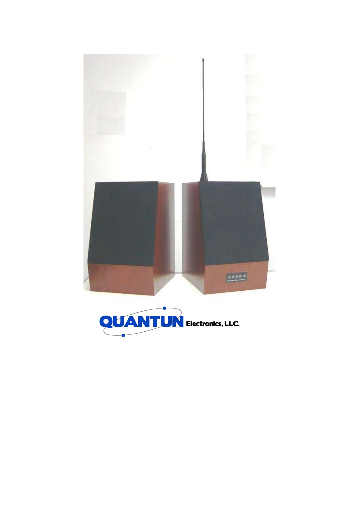
Instruction Manual
Digital Broadcast System 15W+15W Receiver
□ 402MHZ-410MHZ
□ 410MHZ-420MHZ
□ 420MHZ-430MHZ
□ 430MHZ-440MHZ
□ 440MHZ-450MHZ
□ 450MHZ-460MHZ
□ 450MHZ-470MHZ
Page 2

Dear Customer,
Thanks for purchasing the Quantun Wireless Digital
Broadcast System.
We deeply appreciate your choice of buying our DBS. We
believe this product is going to make a positive impact in
the functionality and productivity of your company.
Our Digital Broadcast System is one of our RF solutions
technologically different from any other existing broadcast
systems in the market. The biggest difference is that it is a
“Wireless System”, meaning there is no need to install any
wires between the “Broadcast Console” & “Remote
Terminals”. Additionally, multiple audio sources are fully
integrated to the DBS console simplifying operation and
saving the cost of the additional equipment that may be
required on standard broadcast systems.
Thanks again for your trust in our products. It gives us the
motivation to keep developing quality innovative products
to successfully satisfy your broadcast needs. We strongly
recommend you fully read the operational manual prior to
use the equipment. It will greatly help you to understand
the features and safe operating parameters of our system.
1
Page 3

Cautions for Operation
The Receiver you bought is a high technology product,please operate with care. For
a longer useful life, we offer the following advice:.
■ A 3 Pins AC Power plug is used in the unit. It has a GND pin for protection. Do not
remove it.
■ There are High Voltages inside the unit. To avoid any damage or accidents do not
try to open the unit.
■ Do not install the unit to direct exposure to sunlight, This will limit the service life
on the unit.
■ Please keep the unit away from magnetic fields.
■ To protect this unit from lightning strike,the antenna should be properly installed
and protected, with a ground connection and lighting arrestor, if required
2
Page 4

Content
I.Unpacking
4
II.Features
4
III.Parts Identification
5
IV.Assembly and Installation
6-7
V.Operation Guide
8
VI. Read & Write Operation
VII.Tech Specifications
9
VIII.Trouble Shooting
9
IX.Cautions for Warranty
10
X.Memo
10
XI.Warranty Card
11
3
Page 5
I.Unpacking
Please take the receiver out from the packing box carefully and make sure there are
no items left in the box prior to discard it. If you detect any loss or damage caused
during shipping, please feel free to submit your claim sheet to your reseller without
hesitation.
Accessories
No Item Qty Illustration
Bracket
1
Instruction Manual
2
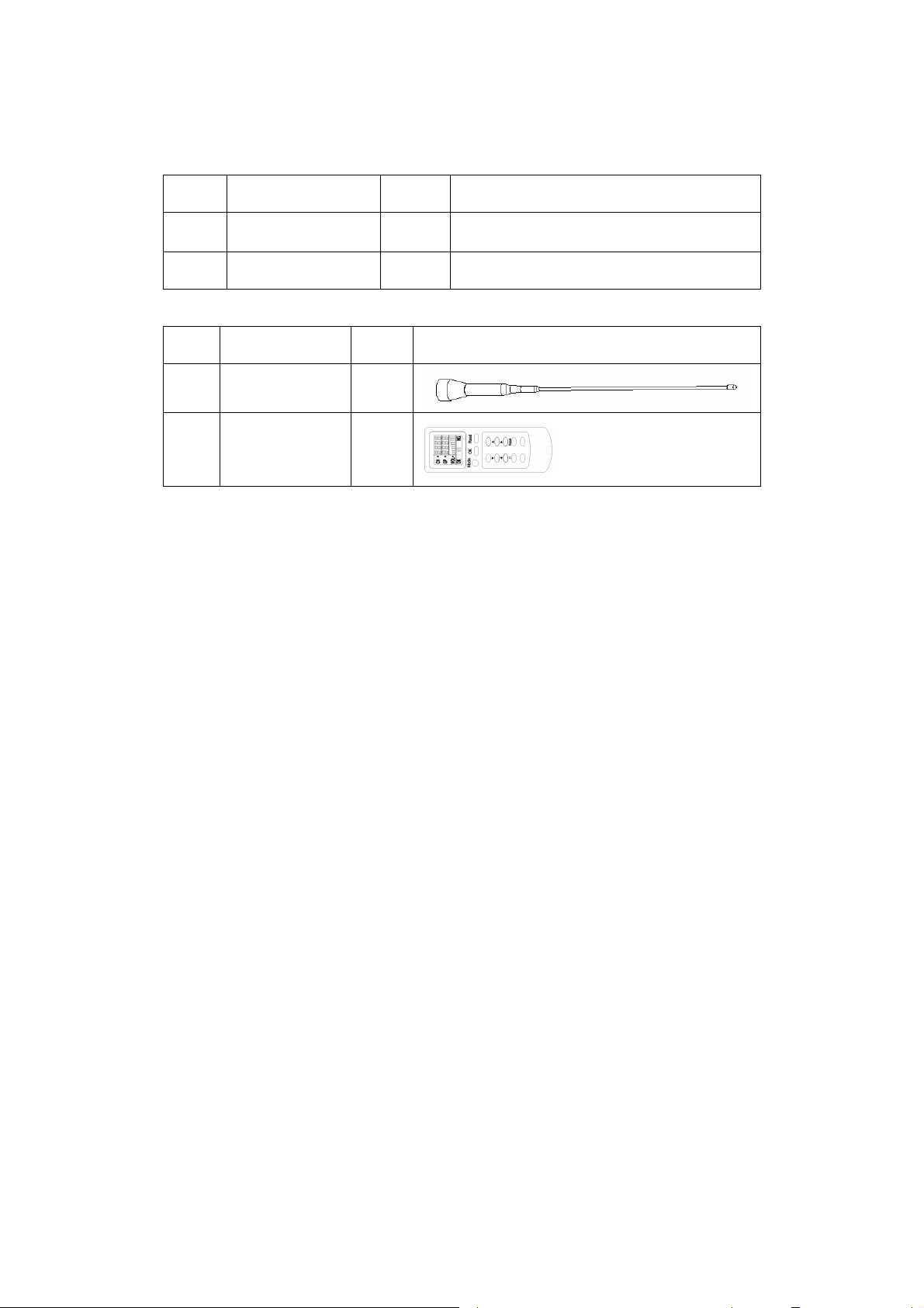
Optional Parts
No Item Qty Illustration
Antenna
1
Remote Control
2
1
1
1
1
II. Features
⑴.Remote Control
⑵.Attractive Design
⑶.Maximum Audio Power output: 30 w over 4 Ohm speaker, or two 15 watt with
satellite speaker option.
⑷.Auto Power saving when in Standby mode.
Internally Switched power supply source
⑸.
⑹.Mute the unit by remote control
⑺.Reset the unit by remote control
⑻. Frequency Agile
(9). Can be used with One 4 Ohm Speaker or two 8 Ohm units.
(10).Wireless Microphone
Page 6

4
III. Parts Identification
1. Receiver +External Speaker
Receiver
2. Receiver Appearance
Speaker Line
External SP
Loudspeaker
Woofer
LED Indicating Window
Antenna
Programming
SPK Line Connection
Battery Switch
Power Cable
Fuse Holder
Bracket
Page 7

IV. Assembly and Installation
1. Antenna Removing & Assembly
⑵. Tighten the screws to assemble the antenna.
5
⑴ . Assemble the antenna as indicated in
illustration below.
⑶.Install the antenna in accordance
with the arrow direction as illustrated
below,to remove the antenna turn in
the opposite direction.
Page 8

6
2.Bracket Assembly and Installation
Tighten/Drive the screws to fix&
remove the bracket.
3.Fuse /SP Line Replacing/Battery Switch
⑴ .Tighten/Drive
the screws to fix
and remove the
bracket.
⑵.
Switch the battery
ON/OFF with the switch.
⑶. Rotate the fuse cap as per
the arrow direction to remove
and replace the fuse.
7
Page 9

V. Operation Guide
1. Unit Switched On,“POWER”(Red LED)will lit solid bright.
2. Signal Received,“DATA ON”(Green LED)will lit solid bright.
3. Standby,“WAKE UP”(Blue LED)will lit solid bright.(the unit will go to sleep when
no signal is received from the DBS for 2 or more minutes)
4. How to Program the new Frequencies in the Receiver.
a. Connect Receiver to PC with the programmable cable, and have the Receiver
Powered.
b. Run the provided programming software.
c. In the programming window, click “Read” to read out frequency of each channel.
d. In programming window, Enter the required frequency, click “Write” to save it.
VI. Read& Write Operation (Keep the remote control 1- 6 meters away and pointing
the receiver window you are trying to program).
1.Channel Selecting: Pressing “CH” under “Mode”,pressing “▲”“▼”to select the
channel(can be set from 0 to 9,valid channels are from 1 to 8)then press “OK”.LCD
will display “OK” or “NG” to indicate whether the implementation has been successful
or not.
2. Group Selecting:Pressing “GP” under “Mode”,then press “▲” “▼” “ ”“ ” to set
the Group ID(can be set from 0 to 9999,valid Groups range is from 1 to 500)then
press “OK” 。 The LCD will display “OK” or “NG” to indicate whether the
implementation was successful or not.
3. Volume Control:Pressing “VOL” under “Mode”,then“▲” “▼”to increase or reduce
the volume level ( level 1- 9)。The LCD will display “OK” or “NG” to indicate whether
the implementation was successful or not,as well as the “current volume level”。
4.Mute:Pressing “MUTE”,Receiver goes to “Silent” if it’s not in “Mute “mode,LCD
will display“ ”
;to exit “Silent “by pressing again, “ ”will disappear。
5. Data Retrieving:Pressing “Read” will get the data from the Receiver,LCD will
display “OK” or “NG” to indicate whether the implementation of “Read” was
successful or not. If “OK”, the LCD will display “CH”、“GP”、“VOL” of the Receiver. It
is always required to perform “Read” prior to change or reprogram the receiver.
6 .Reset:hold down “Reset” button for 3 Sec to reset the unit.
Page 10

8
VII.Tech Specifications
1. Power Supply:110VAC/60HZ and/or 12VDC
2. Modulation Method:GFSK
3. Operating Frequency:402~430MHz
4. Channel Bandwidth: 100 KHZ
5. Channel No:8 CH
6. Sensitivity:≤-110dBm
7. Transmission Data Speed:38.4kbps
8. Modulation Deviation:15KHz
9. Working Temperature:-10℃~60℃
10. Working Humidity:10%~90% Relative Humidity No condensation
11. Dimens i o n :L234mm*W185mm*H300mm (the size of Antenna & Bracket are not
included)
VIII.Troubleshooting
Problems Solutions
1 Please check if the AC Power Cable is properly
Can’t be powered on
connected.
2. Please check if the fuse is OK and making good
contact
Can’t read/write data Please check if the unit in Normal condition.
1. Use the remote control to check the data of the
Receiver, check if the Channel is the same of the DBS
No Signals received
and the Groups ID is active.
2. Please check if the Antenna is properly connected.
No audio output
signal
1. Using the remote control to verify if the unit is in “Mute”
mode.)
2. Please check if the Speaker line is properly connected.
Page 11

9
IX.Cautious for Warranty
1.We offer a 1 year warranty period.
2. If during this warranty period the product you have bought proves defective due to
improper parts or manufacturing, our authorized Service Station or authorized
Service Reseller in your country will repair or replace it at no charge. Our 1 year
limited warranty does not cover:
A.Damages caused by natural disaster (water, fire, earthquake, lightning), or any
improper use that is beyond the control of our company.
B.Problems and malfunctions caused by removing disassembly, repairs done by
user himself or modifications conducted by any non-authorized personal.
C.Any modification or changes to upgrade the product from its normal purpose as
described in the Operating Manual without the prior written consent of our
company.
D.Problems and malfunctions caused by improper settings or Drivers installations
done by the user.
E.Identification Tag or type or serial number or warranty card of the product has
been altered, deleted, removed or made illegible.
F.Problems and malfunctions caused by any other improper operation..
3.A very fast servicing & repairing is offered by our dealer as soon as the receipt of
your defective product.
4. Please keep in your records the Commercial Invoice & Warranty Card together
with the unit at the time it is sent to Service Station Repair and Service.(the
purchasing date will be counted from the date of ex-factory if the Commercial
Invoice and Warranty Card can’t be provided by customer)
Page 12

10
Memo
Page 13

11
XI. Digital Broadcast System Warranty Card (Customer’s Receipt)
Thanks for purchasing our Digital Broadcast System, in the event that any
after-sales services are needed, you are required to contact the Reseller from
whom it was purchased or a member of our authorized Service Network
either via Website or Telephone.
1. Please visit our website given below:
www.quantunelectronics.com
2. Please reach our Technical Support Service at the number given
below:
Tele: 954-651-6300
Purchasing Date:
Dealer Tele:
Dealer Address:
Sales person:
Y M D
*Above blanks are supposed to be completed by the Reseller.
*Please make sure the above said purchasing date is in accord with the date
on the invoice.
* “Warranty Card-Customer’s Receipt” kept by customer himself.
Page 14

12
Digital Broadcast System Warrant Card (Reseller’s Return Receipt)
User Information:
*Name:
□MS Company:
□MR
*Tele: *Cell:
*E-mail:
*Province: Address:
Postal Code:
*For the customer’s rights & interests to be protected,
above*marked items are required to be completed after
confirmation with customer.
Reseller
Information:
Company:
Salesperson:
Tel e: - Ext:
Purchasing Date:
Y M D
Reseller:
*Above blanks are supposed to be completed by the Reseller.
*This “Warranty Card(Reseller’s Return Receipt) is required to be filled
out & cut off by Dealer & has to be shipped to Quantun within 15 days
from the time of purchasing.
Page 15

HTTP://WWW.QUANTUNELECTRONICS.COM
1379 Shotgun Road Sunrise, Florida USA 33326
TEL: 954-651-6300 FAX: 954-651-6311
 Loading...