

WTI RSM-8R4-1, RSM-8R4-2, RSM-8R4-1-DCM, RSM-8R4-2-DCM User Manual

WTI Part No. 13851
Rev. J
RSM-8R Series
Remote Site Manager with Power Control
User's Guide

Secure Racking
If Secure Racked units are installed in a closed or multi-unit rack assembly, they may
require further evaluation by Certification Agencies. The following items must be
considered.
1. The ambient within the rack may be greater than room ambient. Installation
should be such that the amount of air flow required for safe operation is not
compromised. The maximum temperature for the equipment in this environment is
45°C. Consideration should be given to the maximum rated ambient.
2. Installation should be such that a hazardous stability condition is not achieved due
to uneven loading.
Input Supply
Check nameplate ratings to assure there is no overloading of supply circuits that could
have an effect on overcurrent protection and supply wiring.
Grounding
Reliable earthing of this equipment must be maintained. Particular attention should
be given to supply connections when connecting to power strips, rather than direct
connections to the branch circuit.
Warnings and Cautions:
Installation Instructions
No Serviceable Parts Inside; Authorized Service Personnel Only
Do not attempt to repair or service this device yourself. Internal components must be
serviced by authorized personnel only.
• ShockHazard-DoNotEnter
• LithiumBattery
CAUTION:Dangerofexplosionifbatteryisincorrectlyreplaced.Replace
onlywithsameorequivalenttyperecommendedbythemanufacturer.
Discardusedbatteriesaccordingtothemanufacturer'sinstructions.
i

Disconnect Power
If any of the following events are noted, immediately disconnect the unit from the outlet
and contact qualified service personnel:
1. If the power cord becomes frayed or damaged.
2. If liquid has been spilled into the device or if the device has been exposed to rain
or water.
Disconnect Power Before Servicing
Before attempting to service or remove this unit, please make certain to disconnect the
power supply cable from the power source.
Two Power Supply Cables
Note that RSM-8R8-1 and RSM-8R8-2 units feature two separate power inlets, and a
separate power supply cable for each power inlet. Make certain to disconnect both
power supply cables from their power source before attempting to service or remove
the unit.
Modem Cables
Warnings and Cautions
CAUTION: To reduce the risk of fire, use only No. 26 AWG or larger (e.g., 24 AWG) UL
Listed or CSA Certified Telecommunication Line Cord.
ii

Agency Approvals
FCC Part 15 Regulation
This equipment has been tested and found to comply with the limits for a Class A digital
device, pursuant to part 15 of the FCC Rules. These limits are designed to provide
reasonable protection against harmful interference when the equipment is operated
in a commercial environment. This equipment generates, uses, and can radiate radio
frequency energy and, if not installed and used in accordance with the instruction
manual, may cause harmful interference to radio communications. Operation of this
equipment in a residential area is likely to cause harmful interference in which case the
user will be required to correct the interference at his own expense.
This device complies with part 15 of the FCC Rules. Operation is subject to the following
two conditions: (1) This device may not cause harmful interference, and (2) this device
must accept any interference received, including interference that may cause undesired
operation
WARNING: Changes or modifications to this unit not expressly approved by
the party responsible for compliance could void the user’s authority to operate
the equipment
EMC, Safety, and R&TTE Directive Compliance
The CE mark is affixed to this product to confirm compliance with the following
European Community Directives:
• CouncilDirective89/336/EECof3May1989ontheapproximationofthelaws
ofMemberStatesrelatingtoelectromagneticcompatibility;
and
• CouncilDirective73/23/EECof19February1973ontheharmonizationof
thelawsofMemberStatesrelatingtoelectricalequipmentdesignedforuse
withincertainvoltagelimits;
and
• CouncilDirective1999/5/ECof9Marchonradioequipmentand
telecommunicationsterminalequipmentandthemutualrecognitionoftheir
conformity.
Industry Canada - EMI Information
This Class A digital apparatus complies with Canadian ICES-003.
Cet appareil numérique de la classe A est conforme à la norme NMB-003 du Canada.
This product meets the applicable Industry Canada technical specifications
The Ringer Equivalence Number is an indication of the maximum number of devices
allowed to be connected to a telephone interface. The termination on an interface may
consist of any combination of devices subject only to the requirement that the sum of
the RENs of all the devices does not exceed five.
iii

Table of Contents
1. Introduction. . . . . . . . . . . . . . . . . . . . . . . . . . . . . . . . . . . . . . . . . . . . . . . . . . . . . . . . . . . . . 1-1
2. UnitDescription. . . . . . . . . . . . . . . . . . . . . . . . . . . . . . . . . . . . . . . . . . . . . . . . . . . . . . . . . . 2-1
2.1. RSM-8R4 Series - Front Panel Components . . . . . . . . . . . . . . . . . . . . . . . . . . . . . . . . . 2-1
2.2. RSM-8R4 Series - Back Panel Components . . . . . . . . . . . . . . . . . . . . . . . . . . . . . . . . . 2-2
2.3. RSM-8R8 Series - Front Panel Components . . . . . . . . . . . . . . . . . . . . . . . . . . . . . . . . . 2-3
2.4. RSM-8R8 Series - Back Panel Components . . . . . . . . . . . . . . . . . . . . . . . . . . . . . . . . . 2-4
2.5. RSM-8R4-DCM Series - Front Panel Components . . . . . . . . . . . . . . . . . . . . . . . . . . . . 2-5
2.6. Front Panel Button Functions . . . . . . . . . . . . . . . . . . . . . . . . . . . . . . . . . . . . . . . . . . . . . 2-6
3. GettingStarted . . . . . . . . . . . . . . . . . . . . . . . . . . . . . . . . . . . . . . . . . . . . . . . . . . . . . . . . . . 3-1
3.1. Apply Power to the RSM-8R . . . . . . . . . . . . . . . . . . . . . . . . . . . . . . . . . . . . . . . . . . . . . . 3-1
3.2. Connect Your PC to the RSM-8R . . . . . . . . . . . . . . . . . . . . . . . . . . . . . . . . . . . . . . . . . . 3-2
3.3. Communicating with the RSM-8R . . . . . . . . . . . . . . . . . . . . . . . . . . . . . . . . . . . . . . . . . 3-2
3.4. Connecting Ports and Switching Outlets . . . . . . . . . . . . . . . . . . . . . . . . . . . . . . . . . . . . 3-3
4. HardwareInstallation. . . . . . . . . . . . . . . . . . . . . . . . . . . . . . . . . . . . . . . . . . . . . . . . . . . . . 4-1
4.1. Connecting the Power Supply Cables . . . . . . . . . . . . . . . . . . . . . . . . . . . . . . . . . . . . . . 4-1
4.1.1. Installing the Power Supply Cable Keeper . . . . . . . . . . . . . . . . . . . . . . . . . . . . 4-1
4.1.2. Connect the RSM-8R to Your Power Supply . . . . . . . . . . . . . . . . . . . . . . . . . . . 4-1
4.2. Connecting the Network Cable . . . . . . . . . . . . . . . . . . . . . . . . . . . . . . . . . . . . . . . . . . . 4-1
4.3. The Internal Modem Port . . . . . . . . . . . . . . . . . . . . . . . . . . . . . . . . . . . . . . . . . . . . . . . . 4-1
4.4. Connection to Switched Outlets . . . . . . . . . . . . . . . . . . . . . . . . . . . . . . . . . . . . . . . . . . 4-2
4.5. Connecting Devices to the RSM-8R Serial Ports . . . . . . . . . . . . . . . . . . . . . . . . . . . . . . 4-2
5. BasicConfiguration . . . . . . . . . . . . . . . . . . . . . . . . . . . . . . . . . . . . . . . . . . . . . . . . . . . . . . 5-1
5.1. Communicating with the RSM-8R Unit . . . . . . . . . . . . . . . . . . . . . . . . . . . . . . . . . . . . . . 5-1
5.1.1. The Text Interface . . . . . . . . . . . . . . . . . . . . . . . . . . . . . . . . . . . . . . . . . . . . . . . 5-1
5.1.2. The Web Browser Interface . . . . . . . . . . . . . . . . . . . . . . . . . . . . . . . . . . . . . . . . 5-2
5.1.3. Access Via PDA . . . . . . . . . . . . . . . . . . . . . . . . . . . . . . . . . . . . . . . . . . . . . . . . . 5-3
5.2. Configuration Menus . . . . . . . . . . . . . . . . . . . . . . . . . . . . . . . . . . . . . . . . . . . . . . . . . . . 5-4
5.3. Defining System Parameters . . . . . . . . . . . . . . . . . . . . . . . . . . . . . . . . . . . . . . . . . . . . . 5-5
5.3.1. The Real Time Clock and Calendar . . . . . . . . . . . . . . . . . . . . . . . . . . . . . . . . . 5-8
5.3.2. The Invalid Access Lockout Feature . . . . . . . . . . . . . . . . . . . . . . . . . . . . . . . . . 5-9
5.3.3. Log Configuration . . . . . . . . . . . . . . . . . . . . . . . . . . . . . . . . . . . . . . . . . . . . . . 5-12
5.3.3.1. The Audit Log and Alarm Log Configuration Options . . . . . . . . . . . 5-12
5.3.3.2. The Temperature Log . . . . . . . . . . . . . . . . . . . . . . . . . . . . . . . . . . . . 5-13
5.3.3.3. Reading, Downloading and Erasing Logs . . . . . . . . . . . . . . . . . . . . 5-13
5.3.4. Callback Security . . . . . . . . . . . . . . . . . . . . . . . . . . . . . . . . . . . . . . . . . . . . . . . 5-14
5.4. User Accounts . . . . . . . . . . . . . . . . . . . . . . . . . . . . . . . . . . . . . . . . . . . . . . . . . . . . . . . 5-16
5.4.1. Command Access Levels . . . . . . . . . . . . . . . . . . . . . . . . . . . . . . . . . . . . . . . . 5-16
5.4.2. Granting Serial Port Access . . . . . . . . . . . . . . . . . . . . . . . . . . . . . . . . . . . . . . 5-17
5.4.3. Granting Plug Access . . . . . . . . . . . . . . . . . . . . . . . . . . . . . . . . . . . . . . . . . . . 5-17
5.5. Managing User Accounts . . . . . . . . . . . . . . . . . . . . . . . . . . . . . . . . . . . . . . . . . . . . . . . 5-18
5.5.1. Viewing User Accounts . . . . . . . . . . . . . . . . . . . . . . . . . . . . . . . . . . . . . . . . . . 5-18
5.5.2. Adding User Accounts . . . . . . . . . . . . . . . . . . . . . . . . . . . . . . . . . . . . . . . . . . 5-18
5.5.3. Modifying User Accounts . . . . . . . . . . . . . . . . . . . . . . . . . . . . . . . . . . . . . . . . 5-20
5.5.4. Deleting User Accounts . . . . . . . . . . . . . . . . . . . . . . . . . . . . . . . . . . . . . . . . . . 5-21
5.6. The Plug Group Directory . . . . . . . . . . . . . . . . . . . . . . . . . . . . . . . . . . . . . . . . . . . . . . 5-22
5.6.1. Viewing Plug Groups . . . . . . . . . . . . . . . . . . . . . . . . . . . . . . . . . . . . . . . . . . . . 5-22
5.6.2. Adding Plug Groups . . . . . . . . . . . . . . . . . . . . . . . . . . . . . . . . . . . . . . . . . . . . 5-23
5.6.3. Modifying Plug Groups . . . . . . . . . . . . . . . . . . . . . . . . . . . . . . . . . . . . . . . . . . 5-23
5.6.4. Deleting Plug Groups . . . . . . . . . . . . . . . . . . . . . . . . . . . . . . . . . . . . . . . . . . . 5-23
iv

Table of Contents
5. BasicConfiguration(Continued)
5.7. Defining Plug Parameters . . . . . . . . . . . . . . . . . . . . . . . . . . . . . . . . . . . . . . . . . . . . . . . 5-24
5.7.1. The Boot Priority Parameter . . . . . . . . . . . . . . . . . . . . . . . . . . . . . . . . . . . . . . 5-26
5.7.1.1. Example 1: Change Plug 3 to Priority 1 . . . . . . . . . . . . . . . . . . . . . 5-26
5.7.1.2. Example 2: Change Plug 4 to Priority 2 . . . . . . . . . . . . . . . . . . . . . 5-27
5.8. Serial Port Configuration . . . . . . . . . . . . . . . . . . . . . . . . . . . . . . . . . . . . . . . . . . . . . . . 5-28
5.8.1. RS232 Port Modes . . . . . . . . . . . . . . . . . . . . . . . . . . . . . . . . . . . . . . . . . . . . . . 5-28
5.8.2. The Serial Port Configuration Menu . . . . . . . . . . . . . . . . . . . . . . . . . . . . . . . . 5-29
5.8.3. Copying Parameters to Several Serial Ports (Text Interface Only) . . . . . . . . . 5-34
5.9. Network Configuration . . . . . . . . . . . . . . . . . . . . . . . . . . . . . . . . . . . . . . . . . . . . . . . . . 5-35
5.9.1. Network Port Parameters . . . . . . . . . . . . . . . . . . . . . . . . . . . . . . . . . . . . . . . . 5-35
5.9.2. Network Parameters . . . . . . . . . . . . . . . . . . . . . . . . . . . . . . . . . . . . . . . . . . . . 5-37
5.9.2.1. Modem Pooling . . . . . . . . . . . . . . . . . . . . . . . . . . . . . . . . . . . . . . . . 5-40
5.9.3. IP Security . . . . . . . . . . . . . . . . . . . . . . . . . . . . . . . . . . . . . . . . . . . . . . . . . . . . 5-41
5.9.3.1. Adding IP Addresses to the Allow and Deny Lists . . . . . . . . . . . . . 5-42
5.9.3.2. Linux Operators and Wild Cards . . . . . . . . . . . . . . . . . . . . . . . . . . . 5-43
5.9.3.3. IP Security Examples . . . . . . . . . . . . . . . . . . . . . . . . . . . . . . . . . . . . 5-43
5.9.4. Static Route . . . . . . . . . . . . . . . . . . . . . . . . . . . . . . . . . . . . . . . . . . . . . . . . . . . 5-44
5.9.5. Domain Name Server . . . . . . . . . . . . . . . . . . . . . . . . . . . . . . . . . . . . . . . . . . . 5-44
5.9.6. SNMP Access Parameters . . . . . . . . . . . . . . . . . . . . . . . . . . . . . . . . . . . . . . . 5-45
5.9.7. SNMP Trap Parameters . . . . . . . . . . . . . . . . . . . . . . . . . . . . . . . . . . . . . . . . . . 5-46
5.9.8. LDAP Parameters . . . . . . . . . . . . . . . . . . . . . . . . . . . . . . . . . . . . . . . . . . . . . . 5-47
5.9.8.1. Adding LDAP Groups . . . . . . . . . . . . . . . . . . . . . . . . . . . . . . . . . . . . 5-49
5.9.8.2 Viewing LDAP Groups . . . . . . . . . . . . . . . . . . . . . . . . . . . . . . . . . . . 5-49
5.9.8.3. Modifying LDAP Groups . . . . . . . . . . . . . . . . . . . . . . . . . . . . . . . . . 5-50
5.9.8.4. Deleting LDAP Groups . . . . . . . . . . . . . . . . . . . . . . . . . . . . . . . . . . . 5-50
5.9.9. TACACS Parameters . . . . . . . . . . . . . . . . . . . . . . . . . . . . . . . . . . . . . . . . . . . . 5-51
5.9.10. RADIUS Parameters . . . . . . . . . . . . . . . . . . . . . . . . . . . . . . . . . . . . . . . . . . . . 5-53
5.9.10.1. Dictionary Support for RADIUS . . . . . . . . . . . . . . . . . . . . . . . . . . . . 5-54
5.9.11. Email Messaging Parameters . . . . . . . . . . . . . . . . . . . . . . . . . . . . . . . . . . . . . 5-56
5.10. Save User Selected Parameters . . . . . . . . . . . . . . . . . . . . . . . . . . . . . . . . . . . . . . . . . 5-57
5.10.1. Restore Configuration . . . . . . . . . . . . . . . . . . . . . . . . . . . . . . . . . . . . . . . . . . . 5-57
6. RebootOptions. . . . . . . . . . . . . . . . . . . . . . . . . . . . . . . . . . . . . . . . . . . . . . . . . . . . . . . . . . 6-1
6.1. Ping-No-Answer Reboot . . . . . . . . . . . . . . . . . . . . . . . . . . . . . . . . . . . . . . . . . . . . . . . . . 6-2
6.1.1. Adding Ping-No-Answer Reboots . . . . . . . . . . . . . . . . . . . . . . . . . . . . . . . . . . . 6-2
6.1.2. Viewing Ping-No-Answer Reboot Profiles . . . . . . . . . . . . . . . . . . . . . . . . . . . . . 6-4
6.1.3. Modifying Ping-No-Answer Reboot Profiles . . . . . . . . . . . . . . . . . . . . . . . . . . . 6-4
6.1.4. Deleting Ping-No-Answer Reboot Profiles . . . . . . . . . . . . . . . . . . . . . . . . . . . . 6-4
6.2. Scheduled Reboot . . . . . . . . . . . . . . . . . . . . . . . . . . . . . . . . . . . . . . . . . . . . . . . . . . . . . 6-5
6.2.1. Adding Scheduled Reboots . . . . . . . . . . . . . . . . . . . . . . . . . . . . . . . . . . . . . . . 6-5
6.2.2. Viewing Scheduled Reboot Actions . . . . . . . . . . . . . . . . . . . . . . . . . . . . . . . . . 6-6
6.2.3. Modifying Scheduled Reboots . . . . . . . . . . . . . . . . . . . . . . . . . . . . . . . . . . . . . 6-6
6.2.4. Deleting Scheduled Reboots . . . . . . . . . . . . . . . . . . . . . . . . . . . . . . . . . . . . . . 6-6
7. AlarmConfiguration. . . . . . . . . . . . . . . . . . . . . . . . . . . . . . . . . . . . . . . . . . . . . . . . . . . . . . 7-1
7.1. The Over Temperature Alarms . . . . . . . . . . . . . . . . . . . . . . . . . . . . . . . . . . . . . . . . . . . . 7-2
7.1.1. Over Temperature Alarms - Load Shedding and Auto Recovery . . . . . . . . . . . 7-4
7.2. The Circuit Breaker Open Alarm (RSM-8R8 Units Only) . . . . . . . . . . . . . . . . . . . . . . . . 7-6
7.3. The Lost Communication Alarm . . . . . . . . . . . . . . . . . . . . . . . . . . . . . . . . . . . . . . . . . . . 7-7
7.4. The Ping-No-Answer Alarm . . . . . . . . . . . . . . . . . . . . . . . . . . . . . . . . . . . . . . . . . . . . . . 7-9
7.5. The Serial Port Invalid Access Lockout Alarm . . . . . . . . . . . . . . . . . . . . . . . . . . . . . . . 7-11
7.6. The Power Cycle Alarm . . . . . . . . . . . . . . . . . . . . . . . . . . . . . . . . . . . . . . . . . . . . . . . . 7-13
7.7. Buffer Threshold Alarm . . . . . . . . . . . . . . . . . . . . . . . . . . . . . . . . . . . . . . . . . . . . . . . . . 7-14
7.8. The No Dialtone Alarm . . . . . . . . . . . . . . . . . . . . . . . . . . . . . . . . . . . . . . . . . . . . . . . . . 7-16
7.9. The Lost Voltage Alarm . . . . . . . . . . . . . . . . . . . . . . . . . . . . . . . . . . . . . . . . . . . . . . . . 7-18
v

Table of Contents
8. TheStatusScreens. . . . . . . . . . . . . . . . . . . . . . . . . . . . . . . . . . . . . . . . . . . . . . . . . . . . . . . 8-1
8.1. Product Status . . . . . . . . . . . . . . . . . . . . . . . . . . . . . . . . . . . . . . . . . . . . . . . . . . . . . . . . 8-1
8.2. The Network Status Screen . . . . . . . . . . . . . . . . . . . . . . . . . . . . . . . . . . . . . . . . . . . . . . 8-2
8.3. The Port and Plug Status Screens . . . . . . . . . . . . . . . . . . . . . . . . . . . . . . . . . . . . . . . . . 8-2
8.4. The Plug Group Status Screen . . . . . . . . . . . . . . . . . . . . . . . . . . . . . . . . . . . . . . . . . . . 8-5
8.5. The Event Logs . . . . . . . . . . . . . . . . . . . . . . . . . . . . . . . . . . . . . . . . . . . . . . . . . . . . . . . . 8-6
8.5.1. The Audit Log . . . . . . . . . . . . . . . . . . . . . . . . . . . . . . . . . . . . . . . . . . . . . . . . . . 8-6
8.5.2. The Alarm Log . . . . . . . . . . . . . . . . . . . . . . . . . . . . . . . . . . . . . . . . . . . . . . . . . . 8-6
8.5.3. The Temperature Log . . . . . . . . . . . . . . . . . . . . . . . . . . . . . . . . . . . . . . . . . . . . 8-7
8.6. The Port Diagnostics Screen . . . . . . . . . . . . . . . . . . . . . . . . . . . . . . . . . . . . . . . . . . . . . 8-8
8.7. The Port Parameters Screens . . . . . . . . . . . . . . . . . . . . . . . . . . . . . . . . . . . . . . . . . . . . 8-9
9. Operation. . . . . . . . . . . . . . . . . . . . . . . . . . . . . . . . . . . . . . . . . . . . . . . . . . . . . . . . . . . . . . . 9-1
9.1. Controlling Power - Web Browser Interface . . . . . . . . . . . . . . . . . . . . . . . . . . . . . . . . . . 9-1
9.1.1. The Plug Control Screen - Web Browser Interface . . . . . . . . . . . . . . . . . . . . . . 9-1
9.1.2. The Plug Group Control Screen - Web Browser Interface . . . . . . . . . . . . . . . . 9-2
9.2. Controlling Power - Text Interface . . . . . . . . . . . . . . . . . . . . . . . . . . . . . . . . . . . . . . . . . 9-3
9.2.1. The Port and Plug Status Screen - Text Interface . . . . . . . . . . . . . . . . . . . . . . . 9-3
9.2.2. Switching and Reboot Commands - Text Interface . . . . . . . . . . . . . . . . . . . . . 9-3
9.2.2.1. Applying Commands to Several Plugs - Text Interface . . . . . . . . . . . 9-5
9.3. Connecting and Disconnecting Serial Ports - Text Interface . . . . . . . . . . . . . . . . . . . . . 9-6
9.3.1. Any-to-Any Mode . . . . . . . . . . . . . . . . . . . . . . . . . . . . . . . . . . . . . . . . . . . . . . . . 9-6
9.3.1.1. Connecting Ports . . . . . . . . . . . . . . . . . . . . . . . . . . . . . . . . . . . . . . . . 9-6
9.3.1.2. Disconnecting Ports . . . . . . . . . . . . . . . . . . . . . . . . . . . . . . . . . . . . . . 9-8
9.3.1.3. Defining Hunt Groups . . . . . . . . . . . . . . . . . . . . . . . . . . . . . . . . . . . . 9-9
9.3.2. Passive Mode . . . . . . . . . . . . . . . . . . . . . . . . . . . . . . . . . . . . . . . . . . . . . . . . . 9-10
9.3.3. Buffer Mode . . . . . . . . . . . . . . . . . . . . . . . . . . . . . . . . . . . . . . . . . . . . . . . . . . . 9-11
9.3.3.1. Reading Data from Buffer Mode Ports . . . . . . . . . . . . . . . . . . . . . . . 9-11
9.3.3.2. Port Buffers . . . . . . . . . . . . . . . . . . . . . . . . . . . . . . . . . . . . . . . . . . . . 9-12
9.3.4. Modem Mode . . . . . . . . . . . . . . . . . . . . . . . . . . . . . . . . . . . . . . . . . . . . . . . . . 9-13
9.4. Manual Operation . . . . . . . . . . . . . . . . . . . . . . . . . . . . . . . . . . . . . . . . . . . . . . . . . . . . . 9-13
9.5. Logging Out of Command Mode . . . . . . . . . . . . . . . . . . . . . . . . . . . . . . . . . . . . . . . . . 9-13
10.Telnet&SSHFunctions . . . . . . . . . . . . . . . . . . . . . . . . . . . . . . . . . . . . . . . . . . . . . . . . . . 10-1
10.1. Network Port Numbers . . . . . . . . . . . . . . . . . . . . . . . . . . . . . . . . . . . . . . . . . . . . . . . . . 10-1
10.2. SSH Encryption . . . . . . . . . . . . . . . . . . . . . . . . . . . . . . . . . . . . . . . . . . . . . . . . . . . . . . 10-1
10.3. The Direct Connect Feature . . . . . . . . . . . . . . . . . . . . . . . . . . . . . . . . . . . . . . . . . . . . 10-2
10.3.1. Standard Telnet Protocol, SSH and Raw Socket . . . . . . . . . . . . . . . . . . . . . . 10-2
10.3.2. Configuration . . . . . . . . . . . . . . . . . . . . . . . . . . . . . . . . . . . . . . . . . . . . . . . . . . 10-2
10.3.3. Connecting to a Serial Port using Direct Connect . . . . . . . . . . . . . . . . . . . . . 10-4
10.3.4. Terminating a Direct Connect Session . . . . . . . . . . . . . . . . . . . . . . . . . . . . . . 10-5
10.4. Creating an Outbound Telnet Connection . . . . . . . . . . . . . . . . . . . . . . . . . . . . . . . . . . 10-6
10.5. Creating an Outbound SSH Connection . . . . . . . . . . . . . . . . . . . . . . . . . . . . . . . . . . . 10-7
11.SyslogMessages . . . . . . . . . . . . . . . . . . . . . . . . . . . . . . . . . . . . . . . . . . . . . . . . . . . . . . . 11-1
11.1. Configuration . . . . . . . . . . . . . . . . . . . . . . . . . . . . . . . . . . . . . . . . . . . . . . . . . . . . . . . . 11-1
12.SNMPTraps. . . . . . . . . . . . . . . . . . . . . . . . . . . . . . . . . . . . . . . . . . . . . . . . . . . . . . . . . . . . 12-1
12.1. Configuration: . . . . . . . . . . . . . . . . . . . . . . . . . . . . . . . . . . . . . . . . . . . . . . . . . . . . . . . . 12-1
vi

Table of Contents
13.OperationviaSNMP. . . . . . . . . . . . . . . . . . . . . . . . . . . . . . . . . . . . . . . . . . . . . . . . . . . . . 13-1
13.1. RSM-8R SNMP Agent . . . . . . . . . . . . . . . . . . . . . . . . . . . . . . . . . . . . . . . . . . . . . . . . . . 13-1
13.2. SNMPv3 Authentication and Encryption . . . . . . . . . . . . . . . . . . . . . . . . . . . . . . . . . . . 13-1
13.3. Configuration via SNMP . . . . . . . . . . . . . . . . . . . . . . . . . . . . . . . . . . . . . . . . . . . . . . . . 13-2
13.3.1. Viewing Users . . . . . . . . . . . . . . . . . . . . . . . . . . . . . . . . . . . . . . . . . . . . . . . . . 13-3
13.3.2. Adding Users . . . . . . . . . . . . . . . . . . . . . . . . . . . . . . . . . . . . . . . . . . . . . . . . . . 13-3
13.3.3. Modifying Users . . . . . . . . . . . . . . . . . . . . . . . . . . . . . . . . . . . . . . . . . . . . . . . . 13-3
13.3.4. Deleting Users . . . . . . . . . . . . . . . . . . . . . . . . . . . . . . . . . . . . . . . . . . . . . . . . . 13-3
13.4. Plug Control via SNMP . . . . . . . . . . . . . . . . . . . . . . . . . . . . . . . . . . . . . . . . . . . . . . . . . 13-4
13.4.1. Controlling Plugs . . . . . . . . . . . . . . . . . . . . . . . . . . . . . . . . . . . . . . . . . . . . . . . 13-4
13.4.2. Controlling Plug Groups . . . . . . . . . . . . . . . . . . . . . . . . . . . . . . . . . . . . . . . . . 13-4
13.5. Configuring Serial Ports . . . . . . . . . . . . . . . . . . . . . . . . . . . . . . . . . . . . . . . . . . . . . . . . 13-5
13.6. Viewing RSM-8R Status via SNMP . . . . . . . . . . . . . . . . . . . . . . . . . . . . . . . . . . . . . . . . 13-5
13.6.1. Plug Status . . . . . . . . . . . . . . . . . . . . . . . . . . . . . . . . . . . . . . . . . . . . . . . . . . . 13-5
13.6.2. Unit Temperature Status . . . . . . . . . . . . . . . . . . . . . . . . . . . . . . . . . . . . . . . . . 13-5
13.7. Sending Traps via SNMP . . . . . . . . . . . . . . . . . . . . . . . . . . . . . . . . . . . . . . . . . . . . . . . 13-6
14 SettingUpSSLEncryption. . . . . . . . . . . . . . . . . . . . . . . . . . . . . . . . . . . . . . . . . . . . . . . . 14-1
14.1. Creating a Self Signed Certificate . . . . . . . . . . . . . . . . . . . . . . . . . . . . . . . . . . . . . . . . 14-2
14.2. Creating a Signed Certificate . . . . . . . . . . . . . . . . . . . . . . . . . . . . . . . . . . . . . . . . . . . . 14-3
14.3. Downloading the Server Private Key . . . . . . . . . . . . . . . . . . . . . . . . . . . . . . . . . . . . . . 14-4
15.SavingandRestoringConfigurationParameters. . . . . . . . . . . . . . . . . . . . . . . . . . . . . . 15-1
15.1. Sending Parameters to a File . . . . . . . . . . . . . . . . . . . . . . . . . . . . . . . . . . . . . . . . . . . . 15-1
15.2. Restoring Saved Parameters . . . . . . . . . . . . . . . . . . . . . . . . . . . . . . . . . . . . . . . . . . . . 15-2
15.3. Restoring Previously Saved Parameters . . . . . . . . . . . . . . . . . . . . . . . . . . . . . . . . . . . 15-3
16.UpgradingRSM-8RFirmware. . . . . . . . . . . . . . . . . . . . . . . . . . . . . . . . . . . . . . . . . . . . . . 16-1
16.1. Firmware Upgrade Utility (Recommended) . . . . . . . . . . . . . . . . . . . . . . . . . . . . . . . . . 16-1
16.2. The Upgrade Firmware Function (Alternate Method) . . . . . . . . . . . . . . . . . . . . . . . . . 16-1
17.CommandReferenceGuide. . . . . . . . . . . . . . . . . . . . . . . . . . . . . . . . . . . . . . . . . . . . . . . 17-1
17.1. Command Conventions . . . . . . . . . . . . . . . . . . . . . . . . . . . . . . . . . . . . . . . . . . . . . . . . 17-1
17.2. Command Summary . . . . . . . . . . . . . . . . . . . . . . . . . . . . . . . . . . . . . . . . . . . . . . . . . . 17-2
17.3. Command Set . . . . . . . . . . . . . . . . . . . . . . . . . . . . . . . . . . . . . . . . . . . . . . . . . . . . . . . 17-3
17.3.1. Display Commands . . . . . . . . . . . . . . . . . . . . . . . . . . . . . . . . . . . . . . . . . . . . . 17-3
17.3.2. Control Commands . . . . . . . . . . . . . . . . . . . . . . . . . . . . . . . . . . . . . . . . . . . . . 17-5
17.3.3. Configuration Commands . . . . . . . . . . . . . . . . . . . . . . . . . . . . . . . . . . . . . . . 17-12
Appendices:
A. InterfaceDescription. . . . . . . . . . . . . . . . . . . . . . . . . . . . . . . . . . . . . . . . . . . . . . . . . . . . Apx-1
A.1. Serial Port (RS232) . . . . . . . . . . . . . . . . . . . . . . . . . . . . . . . . . . . . . . . . . . . . . . . . . . . Apx-1
B. ConnectingDevicestotheRSM-8R. . . . . . . . . . . . . . . . . . . . . . . . . . . . . . . . . . . . . . . . Apx-2
B.1. Straight RJ-45 Cables and Rollover RJ-45 Cables . . . . . . . . . . . . . . . . . . . . . . . . . . Apx-2
B.2. Connecting DB-9M DTE Devices . . . . . . . . . . . . . . . . . . . . . . . . . . . . . . . . . . . . . . . . Apx-3
B.3. Connecting DB-25F DTE Devices . . . . . . . . . . . . . . . . . . . . . . . . . . . . . . . . . . . . . . . Apx-4
B.4. Connecting DB-25F DCE Devices . . . . . . . . . . . . . . . . . . . . . . . . . . . . . . . . . . . . . . . Apx-5
B.5. Connecting RJ-45 DCE Devices . . . . . . . . . . . . . . . . . . . . . . . . . . . . . . . . . . . . . . . . Apx-6
B.6. DX9F-NULL-RJ Snap Adapter . . . . . . . . . . . . . . . . . . . . . . . . . . . . . . . . . . . . . . . . . . Apx-6
C. RSM-8R4-DCMMountingOptions. . . . . . . . . . . . . . . . . . . . . . . . . . . . . . . . . . . . . . . . . Apx-7
C.1 Wall Mounting . . . . . . . . . . . . . . . . . . . . . . . . . . . . . . . . . . . . . . . . . . . . . . . . . . . . . . . Apx-7
C.2 Rack Mounting . . . . . . . . . . . . . . . . . . . . . . . . . . . . . . . . . . . . . . . . . . . . . . . . . . . . . . Apx-8
C.3. DIN Rail Mounting . . . . . . . . . . . . . . . . . . . . . . . . . . . . . . . . . . . . . . . . . . . . . . . . . . . Apx-9
D. Specifications. . . . . . . . . . . . . . . . . . . . . . . . . . . . . . . . . . . . . . . . . . . . . . . . . . . . . . . . Apx-10
E. CustomerService. . . . . . . . . . . . . . . . . . . . . . . . . . . . . . . . . . . . . . . . . . . . . . . . . . . . . Apx-11
vii

List of Figures
2.1. RSM-8R4 Series - Front Panel . . . . . . . . . . . . . . . . . . . . . . . . . . . . . . . . . . . . . . . . . . . . . . . 2-1
2.2. RSM-8R4-1 - Back Panel . . . . . . . . . . . . . . . . . . . . . . . . . . . . . . . . . . . . . . . . . . . . . . . . . . . 2-2
2.3. RSM-8R4-2 - Back Panel . . . . . . . . . . . . . . . . . . . . . . . . . . . . . . . . . . . . . . . . . . . . . . . . . . . 2-2
2.4. RSM-8R8-1 & RSM-8R8-2 - Front Panel . . . . . . . . . . . . . . . . . . . . . . . . . . . . . . . . . . . . . . . 2-3
2.5. RSM-8R8-1 - Back Panel . . . . . . . . . . . . . . . . . . . . . . . . . . . . . . . . . . . . . . . . . . . . . . . . . . . 2-4
2.6. RSM-8R8-2 - Back Panel . . . . . . . . . . . . . . . . . . . . . . . . . . . . . . . . . . . . . . . . . . . . . . . . . . . 2-4
2.7. RSM-8R4-1-DCM - Front Panel . . . . . . . . . . . . . . . . . . . . . . . . . . . . . . . . . . . . . . . . . . . . . . 2-5
2.8. RSM-8R4-2-DCM - Back Panel . . . . . . . . . . . . . . . . . . . . . . . . . . . . . . . . . . . . . . . . . . . . . . 2-5
5.1. Boot Priority Example 1 . . . . . . . . . . . . . . . . . . . . . . . . . . . . . . . . . . . . . . . . . . . . . . . . . . . 5-26
5.2. Boot Priority Example 2 . . . . . . . . . . . . . . . . . . . . . . . . . . . . . . . . . . . . . . . . . . . . . . . . . . . 5-27
14.1. Web Access Parameters (Text Interface Only) . . . . . . . . . . . . . . . . . . . . . . . . . . . . . . . . . 14-1
A.1. Serial Port Interface . . . . . . . . . . . . . . . . . . . . . . . . . . . . . . . . . . . . . . . . . . . . . . . . . . . . Apx-1
B.1. Straight Cables . . . . . . . . . . . . . . . . . . . . . . . . . . . . . . . . . . . . . . . . . . . . . . . . . . . . . . . . Apx-2
B.2. Rollover Cables . . . . . . . . . . . . . . . . . . . . . . . . . . . . . . . . . . . . . . . . . . . . . . . . . . . . . . . . Apx-2
B.3. DX9F-DTE-RJ Snap Adapter Interface . . . . . . . . . . . . . . . . . . . . . . . . . . . . . . . . . . . . . . Apx-3
B.4. Connecting DB-9M DTE Devices to an RJ-45 Serial Port on an RSM-8R . . . . . . . . . . . Apx-3
B.5. DX25M-DTE-RJ Snap Adapter Interface . . . . . . . . . . . . . . . . . . . . . . . . . . . . . . . . . . . . . Apx-4
B.6. Connecting DB-25F DTE Devices to an RJ-45 Serial Port on an RSM-8R . . . . . . . . . . . Apx-4
B.7. DX25M-DCE-RJ Snap Adapter Interface. . . . . . . . . . . . . . . . . . . . . . . . . . . . . . . . . . . . . Apx-5
B.8. Connecting DB-25F DCE Devices to an RJ-45 Serial Port on an RSM-8R . . . . . . . . . . Apx-5
B.9. Connecting RJ-45 DCE Devices to the RSM-8R . . . . . . . . . . . . . . . . . . . . . . . . . . . . . . . Apx-6
B.10. DX9F-NULL-RJ Snap Adapter Interface . . . . . . . . . . . . . . . . . . . . . . . . . . . . . . . . . . . . . Apx-6
C.1. Wall Mounting (Front Panel Facing Upwards) . . . . . . . . . . . . . . . . . . . . . . . . . . . . . . . . Apx-7
C.2. Rack Mounting - Attaching Rack Mount Brackets to DCM-8R4 . . . . . . . . . . . . . . . . . . Apx-8
C.3. Rack Mounting - Installing DCM-8R4 in Equipment Rack . . . . . . . . . . . . . . . . . . . . . . . Apx-8
C.4. DIN Rail Mounting . . . . . . . . . . . . . . . . . . . . . . . . . . . . . . . . . . . . . . . . . . . . . . . . . . . . . Apx-9
Table of Contents
viii

1. Introduction
WTI’s RSM-8R series Remote Site Manager + Power Control units allow secure, remote
monitoring and management of AC powered rack mount equipment via SSL, SSH,
SNMP, web browser, telnet, internal modem or local terminal. The RSM-8R allows you
to connect to console ports on rack mounted devices, switch and reboot power, monitor
equipment temperature and can automatically notify you when changes in temperature
or response to ping commands exceeds user-defined threshold values.
Security and Co-Location Features:
Secure Shell (SSHv2) encryption and address-specific IP security masks help to prevent
unauthorized access to command and configuration functions.
The RSM-8R also provides four different levels of security for user accounts:
Administrator, SuperUser, User and ViewOnly. The Administrator level provides
complete access to all serial port and switched plug functions, status displays and
configuration menus. The SuperUser level allows control of serial ports and plugs, but
does not allow access to configuration functions. The User level allows access to only a
select group of Administrator-defined serial ports and plugs. The ViewOnly level allows
you to check unit status, but does not allow control of serial ports or switched outlets or
access to configuration menus.
The RSM-8R includes full Radius, LDAP and TACACS capability, DHCP and an invalid
access lockout feature. An Audit Log records all user access, login and logout times
and command actions, and an Alarm Log records user-defined alarm events.
Environmental Monitoring and Management:
The RSM-8R can constantly monitor temperature levels, ping response and other
factors. If the RSM-8R detects that user defined thresholds for these values have
been exceeded, the unit can promptly notify you via email, SNMP, or Syslog. When
temperature readings exceed user-defined critical values, the RSM-8R can also
intelligently decrease the amount of heat being generated within the rack by temporarily
shutting down nonessential devices; when readings return to acceptable levels, the
RSM-8R can restore power to those devices to return to normal operating conditions.
The RSM-8R also records temperature readings to a convenient log file.
If you need to switch power to rack mount devices at a specific time of the day or week,
the RSM-8R also includes a Scheduled Power Management feature, that allows you to
define a daily or weekly schedule for switching each outlet off or on, or even rebooting
that outlet.
The RSM-8R can also notify you when excessive invalid access attempts are detected,
and can automatically lock ports when it determines that an unauthorized user may be
attempting to gain access by "hammering" the unit with random passwords.
1-1
WTI Management Utility
The RSM-8R includes the WTI Device Management Utility (DMU,) which allows you to
manage multiple WTI units via a single menu. For more information on the Management
Utility, please refer to the DMU User’s Guide that can be downloaded from the WTI web
site at: http://www.wti.com/t-product-manuals.aspx.
Model Numbers
The RSM-8R series includes both 120 VAC and 240 VAC models to accommodate a
variety of data center applications and power distribution needs.
Introduction
Model No.
RSM-8R4-1 4 100 to 120 VAC 15 Amp 12 Amps*
RSM-8R4-2 4 100 to 240 VAC 15 Amp 12 Amps*
RSM-8R4-1-DCM 4 100 to 120 VAC 15 Amp 12 Amps*
RSM-8R4-2-DCM 4 100 to 240 VAC 15 Amp 12 Amps*
RSM-8R8-1** 8 2 ea., 100 to 132 VAC** 20 Amp 16 Amps*
RSM-8R8-2*** 8 2 ea., 200 to 240 VAC*** 20 Amp 16 Amps*
Outlets
* In accordance with UL requirements for branch circuits, this value has been
de-rated to 80%.
** The input voltage for RSM-8R8-1 units must be between 100 and 132 VAC.
Other voltages will cause damage to the unit.
*** The input voltage for RSM-8R8-2 units must be between 200 and 240 VAC.
Other voltages will cause damage to the unit.
Typographic Conventions
^ (e.g. ^X) Indicates a control character. For example, the text
"^X" (Control X) indicates the [Ctrl] key and the [X]
key must be pressed simultaneously.
Total
Input
Voltage
Input
Feed
Max. Load
COURIER FONT Indicates characters typed on the keyboard.
For example, /RB or /ON 2.
[BoldFont] Text set in bold face and enclosed in square brackets,
indicates a specific key. For example, [Enter] or [Esc].
< > Indicates required keyboard entries:
For Example: /P <n>.
[ ] Indicates optional keyboard entries.
For Example: /P [n].
1-2

2. Unit Description
2.1. RSM-8R4 Series - Front Panel Components
www.wti.com
PWR
CLEAR
ON
2
1
STATUS
SET
RDY
DCD
4
3
5
ACTIVITY
1 2 3 4 5 6 7 8
6
Remote Site Manager + Power Control
RSM-8R4
Figure 2.1: RSM-8R4 Series - Front Panel
As shown in Figure 2.1, the front panel on RSM-8R4 series units includes the following
components:
CLEARButton: Restarts the RSM-8R4 as described in Section 2.6.
PowerOnIndicator: An LED Indicator which lights when AC Power is applied to
the unit.
SETButton: Switches all plugs Off or sets plugs to default values as described in
Section 2.6.
RDYIndicator: (Ready) Flashes to indicate that the unit is ready to receive
commands.
DCDIndicator: The Data Carrier Detect indicator.
ActivityIndicators: A series of LEDs, which light to indicate data activity at the
corresponding RSM-8R4 Serial Port.
2-1
Unit Description
1
2
PLUG 1 PLUG 2 PLUG 3 PLUG 4
3
ACT LINK
Ethernet 10/100 PHONE LINE
6
5
7
I
O
4
SETUP
PORTS
SERIAL PORTS
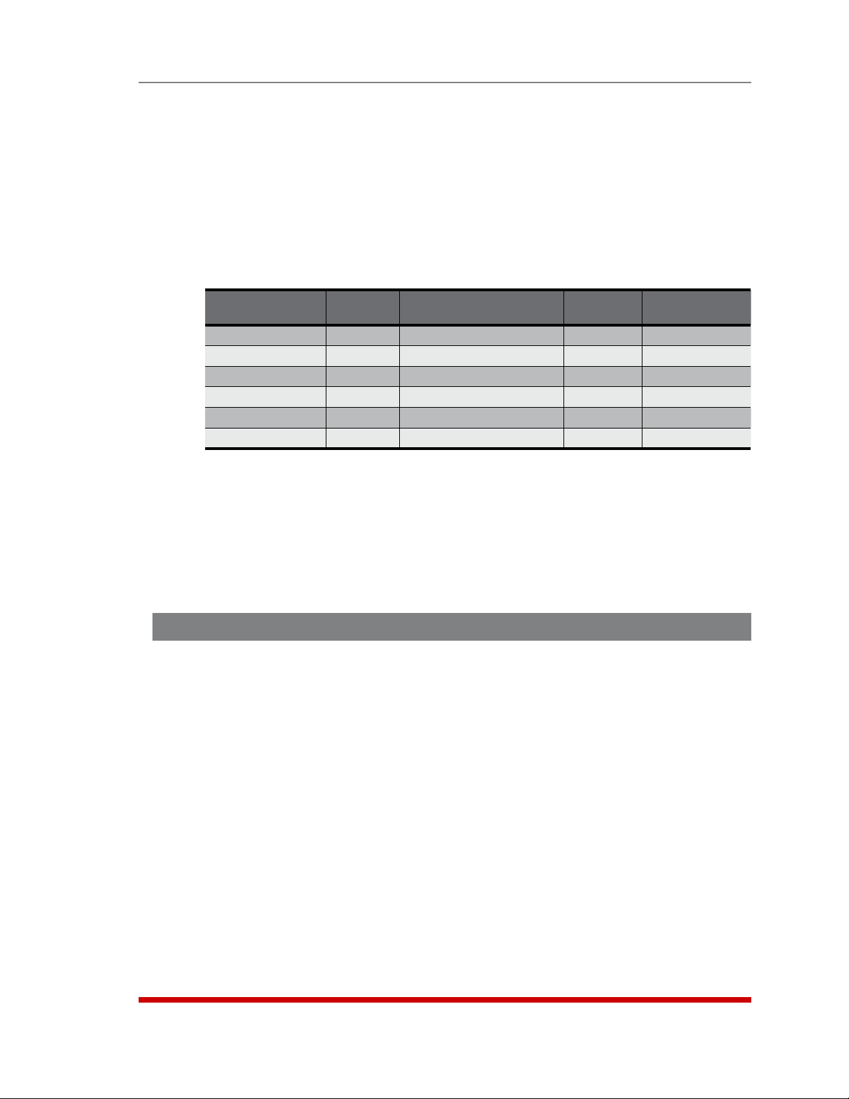
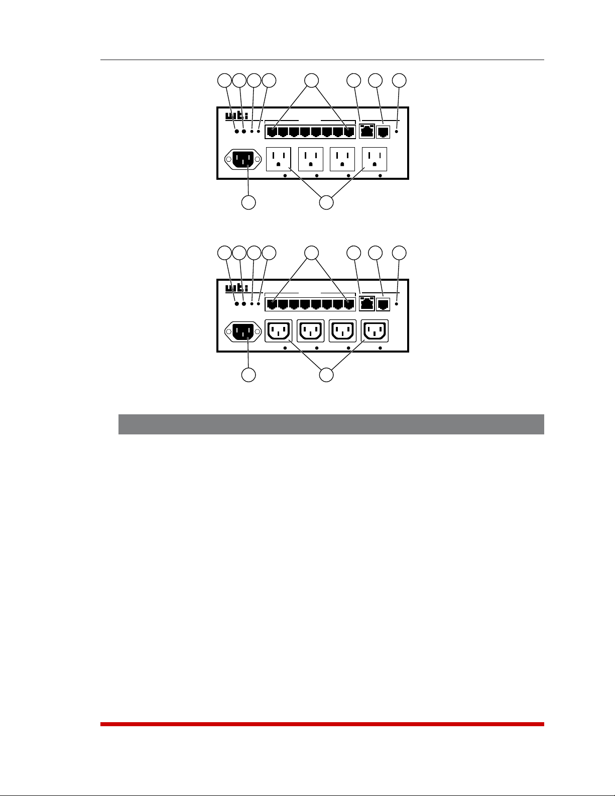
Figure 2.2: RSM-8R4-1 - Back Panel
1
2
PLUG 1 PLUG 2 PLUG 3 PLUG 4
3
ACT LINK
Ethernet 10/100 PHONE LINE
6
5
7
I
O
4
SETUP
PORTS
SERIAL PORTS
Figure 2.3: RSM-8R4-2 - Back Panel
2.2. RSM-8R4 Series - Back Panel Components
As shown in Figures 2.2 and 2.3, the back panel on RSM-8R4 series units includes the
following components:
PowerInlet: An IEC320-C14 AC inlet which supplies power to the RSM-8R4's
control functions and switched power outlets. Also includes cable keeper
(not shown.)
CircuitBreaker: The circuit breaker is rated as follows:
• RSM-8R4-1: 15 Amp Circuit Breaker.
• RSM-8R4-2: 10 Amp Circuit Breaker.
SwitchedOutlets: Four AC Outlets that can be switched On, Off or rebooted in
response to user commands:
• RSM-8R4-1: Four (4) each, NEMA 5-15R Outlets.
• RSM-8R4-2: Four (4) each, IEC320-C13 Outlets.
SerialPorts: For connection to console ports on target devices. Standard RJ45
connectors configured as DCE ports. For more information on connecting devices
to the serial ports, please refer to Section 4.5 and Appendix B. For a description of
the serial port interface, please refer to Appendix A.1.
PowerOn/OffSwitch
NetworkPort: An RJ45 Ethernet port for connection to your 10Base-T or
100Base-T, TCP/IP network. Note that the RSM-8R4 features a default IP address
(192.168.168.168). This allows you to connect to the unit without first assigning an
IP address. The Network Port also includes two LED indicators for Link and Data
Activity. For more information on port configuration, please refer to Section 5.9.
InternalModemPort: For connection to your external phone line. For more
information on Modem Port configuration, please refer to Section 5.8.
2-2
Unit Description
RSM-8R8
Remote Site Manager
+
Power Control
PHONE
www.wti.com
SET UP
ACT LINK
1 2 3 4 5 6 7 8
Ethernet
SERIAL PORTS
ACTIVITY
1 2 3 4 5 6 7 8
RESET DEFAULT
STATUS
ON RDY DCD
OUTPUT STATUS
1 2 3 4
5 6 7 8
1 2 3 4 5 6 7 8 9 10
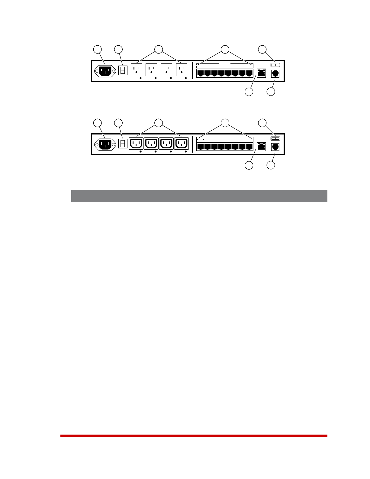
Figure 2.4: RSM-8R8-1 & RSM-8R8-2 - Front Panel
2.3. RSM-8R8 Series - Front Panel Components
As shown in Figure 2.4, the front panel on RSM-8R8 series units includes the following
components:
InternalModemPort: For connection to your external phone line. For more
information on Modem Port configuration, please refer to Section 5.8.
NetworkPort: An RJ45 Ethernet port for connection to your 10Base-T or
100Base-T, TCP/IP network. Note that the RSM-8R8 features a default IP address
(192.168.168.168). This allows you to connect to the unit without first assigning an
IP address. The Network Port also includes two LED indicators for Link and Data
Activity. For more information on port configuration, please refer to Section 5.9.
SerialPorts: For connection to console ports on target devices. Standard RJ45
connectors configured as DCE ports. For more information on connecting devices
to the serial ports, please refer to Section 4.5 and Appendix B. For a description of
the serial port interface, please refer to Appendix A.1.
ActivityIndicators: A series of LEDs, which light to indicate data activity at the
corresponding RSM-8R8 Serial Port.
RESETButton: Restarts the RSM-8R4 as described in Section 2.6.
DEFAULTButton: Switches all plugs Off or sets plugs to default values as
described in Section 2.6.
ONIndicator: An LED Indicator which lights when AC Power is applied to
the unit.
RDYIndicator: (Ready) Flashes to indicate that the unit is ready to receive
commands.
DCDIndicator: The Data Carrier Detect indicator.
OutputStatusIndicators: A series of eight LED indicators which light when power
is applied to the corresponding switched outlet.
Note: Providing that power is still present at the secondary power inlet, the
Output Status indicators will blink on and off when the primary power source is
lost or disconnected.
2-3
PRIMARY SECONDARY A1 A2 A3 A4 A5 A6 A7 A8
Unit Description
1
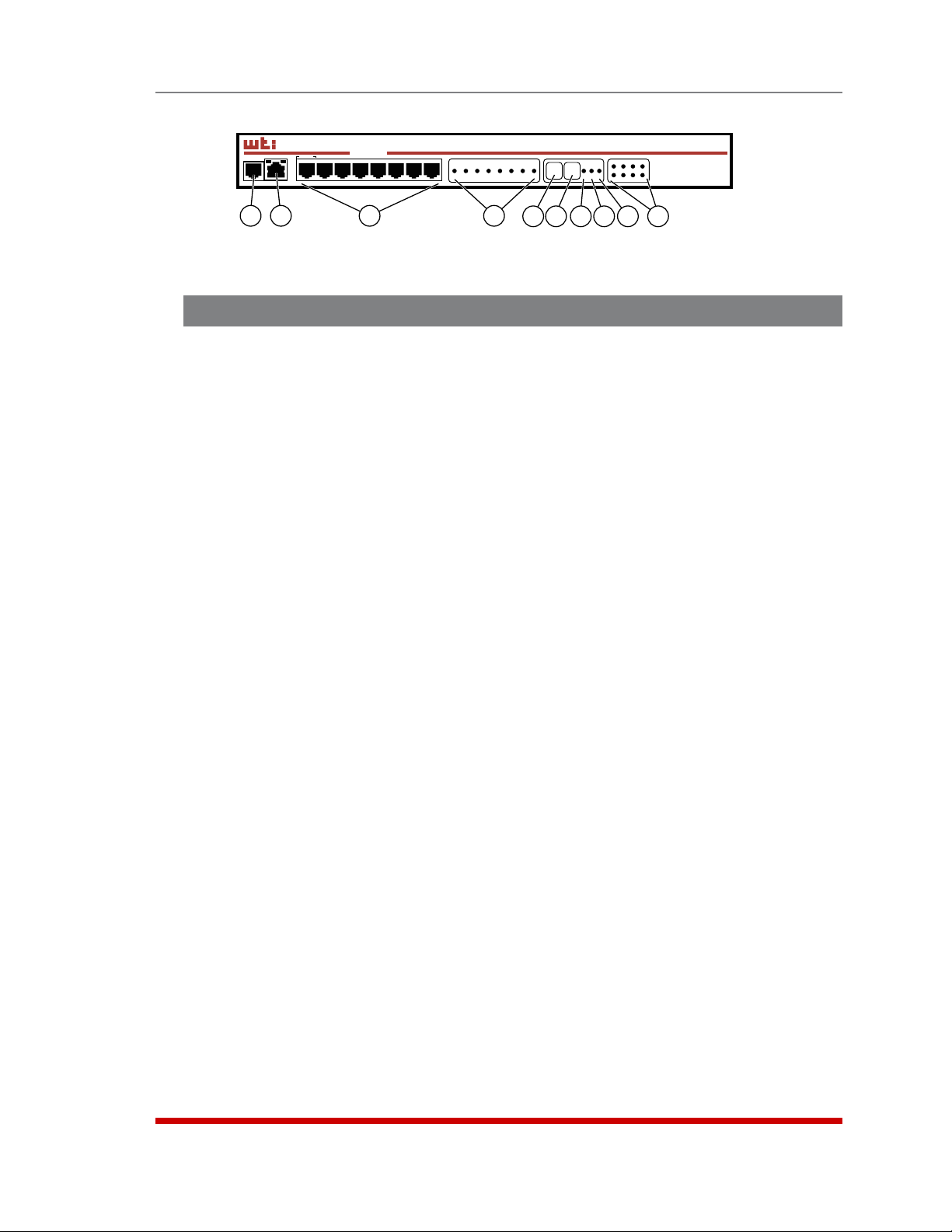
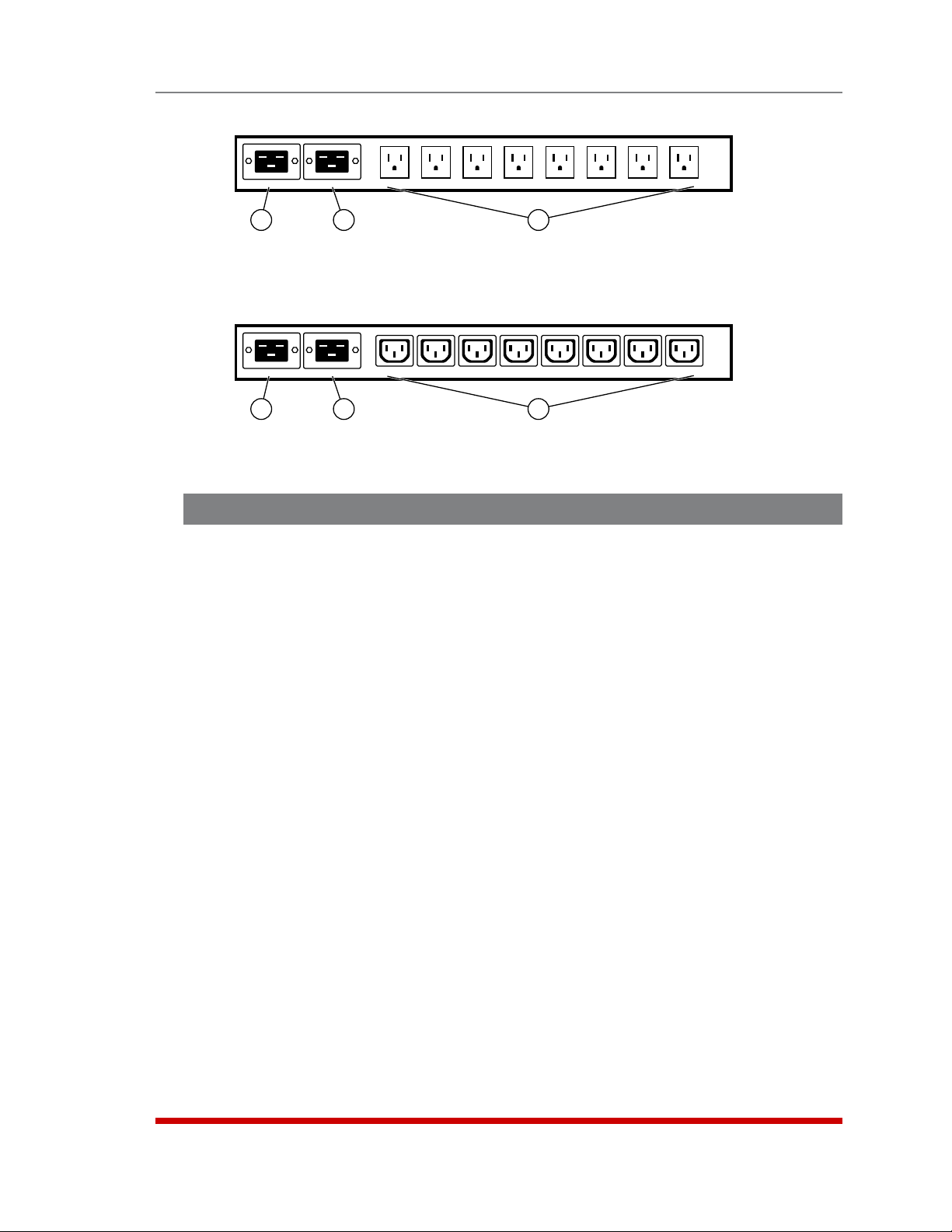
Figure 2.5: RSM-8R8-1 - Back Panel
PRIMARY SECONDARY A1 A2 A3 A4 A5 A6 A7 A8
1
Figure 2.6: RSM-8R8-2 - Back Panel
2
2
3
3
2.4. RSM-8R8 Series - Back Panel Components
As shown in Figures 2.5 and 2.6, the back panel on RSM-8R8 series units includes the
following components:
PrimaryPowerInlet: An IEC320-C20 AC inlet which supplies primary power to the
RSM-8R8's control functions and switched power outlets. Note that the RSM-8R8
includes two power inlets in order to allow connection to a primary and secondary
(fallback) power supply. Also includes cable keeper (not shown.)
SecondaryPowerInlet: An IEC320-C20 AC inlet which supplies secondary
(fallback) power to the RSM-8R8's control functions and switched power outlets.
Note that the RSM-8R8 includes two power inlets in order to allow connection to a
primary and secondary (fallback) power supply. Also includes cable keeper
(not shown.)
SwitchedOutlets: Eight AC Outlets that can be switched On, Off or rebooted in
response to user commands:
• RSM-8R8-1: Eight (8) each, NEMA 5-15R Outlets.
• RSM-8R8-2: Eight (8) each, IEC320-C13 Outlets.
2-4
Unit Description
4
2
1
3
5
7
6
8
SERIAL PORTS
ACT
DEF RST
RDY
2 1 3 4 5 6 7 8
SETUP PORT
A 1
A 2 A 3 A 4
9
Figure 2.7: RSM-8R4-1-DCM - Front Panel
4
2
1
3
DEF RST
RDY
ACT
SETUP PORT
A 1
5
SERIAL PORTS
2 1 3 4 5 6 7 8
A 2 A 3 A 4
9
Figure 2.8: RSM-8R4-2-DCM - Back Panel
10
10
RSM-8R4
ACT LINK
DCD
PHONE
Ethernet
LINE
7
6
ACT LINK
Ethernet
RSM-8R4
PHONE
LINE
8
DCD
2.5. RSM-8R4-DCM Series - Front Panel Components
As shown in Figures 2.7 and 2.8, the front panel on RSM-8R4-DCM series units includes
the following components:
DEFButton(Default): Switches all plugs Off or sets plugs to default values as
described in Section 2.6.
RSTButton(Reset): Restarts the RSM-8R4-DCM as described in Section 2.6.
RDYIndicator: (Ready) Flashes to indicate that the unit is ready to receive
commands.
ACTIndicator(PortActivity): An LED indicator, which lights to indicate data
activity at the RSM-8R4-DCM Serial Ports.
SerialPorts: For connection to console ports on target devices. Standard RJ45
connectors configured as DCE ports. For more information on connecting devices
to the serial ports, please refer to Section 4.5 and Appendix B. For a description of
the serial port interface, please refer to Appendix A.1.
2-5

NetworkPort: An RJ45 Ethernet port for connection to your 10Base-T or
100Base-T, TCP/IP network. Note that the RSM-8R4-DCM features a default IP
address (192.168.168.168). This allows you to connect to the unit without first
assigning an IP address. The Network Port also includes two LED indicators for
Link and Data Activity. For more information on port configuration, please refer to
Section 5.9.
InternalModemPort: For connection to your external phone line. For more
information on Modem Port configuration, please refer to Section 5.8.
DCDIndicator: The Data Carrier Detect indicator.
PowerInlet: An IEC320-C14 AC inlet which supplies power to the RSM-8R4-DCM's
control functions and switched power outlets. Also includes cable keeper
(not shown.)
SwitchedOutlets: Four AC Outlets that can be switched On, Off or rebooted in
response to user commands:
• RSM-8R4-1: Four (4) each, NEMA 5-15R Outlets.
• RSM-8R4-2: Four (4) each, IEC320-C13 Outlets.
2.6. Front Panel Button Functions
Unit Description
The front panel buttons can be used to perform several functions described below:
Notes:
• Front Panel button functions can also be disabled via the System Parameters
menu, as described in Section 5.3.
• When the RSM-8R is reset to factory defaults, all user-defined configuration
parameters will be cleared and the default “super” user account will also be
restored.
• When the RSM-8R is reinitialized, all ports will be disconnected.
• During the reboot procedure, all port activity LEDs will flash once.
1. RebootOperatingSystem-KeepUser-DefinedParameters:
a) Press and hold the CLEAR or RESET button for five seconds, and then release.
b) The RSM-8R operating system will reboot ; all user-defined parameters will be
retained.
2. RebootOperatingSystem-ResetAllParameterstoFactoryDefaults:
a) Simultaneously press both the SET or DEFAULT button and the CLEAR or
RESET button, hold them for five seconds, and then release them.
b) The RSM-8R operating system will reboot; all user-defined parameters will be
reset to factory default settings.
2-6
3. Getting Started
This section describes a simplified installation procedure for the RSM-8R hardware,
which will allow you to communicate with the unit in order to demonstrate basic features
and check for proper operation.
Note that this Quick Start procedure does not provide a detailed description of unit
configuration, or discuss advanced operating features in detail. For more information,
please refer to the remainder of this User’s Guide
3.1. Apply Power to the RSM-8R
Refer to the safety precautions listed at the beginning of this User's Guide, and then
connect the unit to an appropriate power source. Connect the power supply cable to
the unit’s power inlet, snap the Cable Keeper into place, and then connect the cable to
an appropriate power supply. Please refer to the table below for information concerning
power requirements and maximum load. Note that RSM-8R8 series units feature two
power inlets.
Model No.
RSM-8R4-1 4 100 to 120 VAC 15 Amp 12 Amps*
RSM-8R4-2 4 100 to 240 VAC 15 Amp 12 Amps*
RSM-8R4-1-DCM 4 100 to 120 VAC 15 Amp 12 Amps*
RSM-8R4-2-DCM 4 100 to 240 VAC 15 Amp 12 Amps*
RSM-8R8-1** 8 2 ea., 100 to 132 VAC** 20 Amp 16 Amps*
RSM-8R8-2*** 8 2 ea., 200 to 240 VAC*** 20 Amp 16 Amps*
Total
Outlets
Input
Voltage
Input Feed
Max. Load
* In accordance with UL requirements for branch circuits, this value has been
de-rated to 80%.
** The input voltage for RSM-8R8-1 units must be between 100 and 132 VAC.
Other voltages will cause damage to the unit.
*** The input voltage for RSM-8R8-2 units must be between 200 and 240 VAC.
Other voltages will cause damage to the unit.
When power is applied to the RSM-8R, the ON LED on the instrument front panel should
light, and the RDY LED should begin to flash within 90 seconds. This indicates that the
unit is ready to receive commands.
3-1

Getting Started
3.2. Connect Your PC to the RSM-8R
The RSM-8R can either be controlled by a local PC Serial Port, controlled via modem, or
controlled via TCP/IP network. In order to select parameters, connect ports or control
outlets, commands are issued to the RSM-8R via either the Network Port, Modem Port
or Serial Setup Port.
• NetworkPort: Connect the your 10Base-T or 100Base-T network interface to the
RSM-8R 10/100Base-T Network Port.
• SerialPort: Use the supplied Ethernet cable and RJ45 to DB-9 adapter to connect
your PC COM port to Serial Port 1 (the System SetUp Port.) For a description of the
Serial Port Interface, please refer to Appendix A.1.
• Modem: Connect your telephone line to the RSM-8R Phone Line (Modem) Port.
3.3. Communicating with the RSM-8R
When properly installed and configured, the RSM-8R will allow command mode access
via Telnet, Web Browser, SSH client, modem, or local PC. However, in order to ensure
security, both Telnet and Web Browser access are disabled in the default state. To
enable Telnet and/or Web Browser access, please refer to Section 5.9.2.
Notes:
• Default RSM-8R serial port parameters are set as follows: 9600 bps, RTS/
CTS Handshaking, 8 Data Bits, One Stop Bit, No Parity. Although these
parameters can be easily redefined, for this Quick Start procedure, it is
recommended to configure your communications program to accept the
default parameters.
• The RSM-8R features a default IP Address (192.168.168.168) and a default
Subnet Mask (255.255.255.0.) This allows network access to command
mode, providing that you are contacting the RSM-8R from a node on the
same subnet. When attempting to access the RSM-8R from a node that is
not on the same subnet, please refer to Section 5.9 for further configuration
instructions.
1. AccessCommandMode:The RSM-8R includes two separate user interfaces;
the Text Interface and the Web Browser Interface. The Text Interface is available
via Local PC, SSH Client, Telnet, or Modem and can be used to both configure the
RSM-8R and create connections between ports. The Web Browser interface is only
available via TCP/IP network, and can be used to configure the unit, but cannot
create connections between ports.
a) ViaLocalPC: Start your communications program and then
press [Enter].
b) ViaSSHClient: Start your SSH client, enter the default IP address
(192.168.168.168) for the RSM-8R and invoke the connect command.
c) ViaWebBrowser: Make certain that Web Browser access is enabled as
described in Section 5.9.2. Start your JavaScript enabled Web Browser, enter
the default RSM-8R IP address (192.169.168.168) in the Web Browser address
bar, and then press [Enter].
3-2

Getting Started
d) ViaTelnet: Make certain that Telnet access is enabled as described in
Section 5.9.2. Start your Telnet client, and enter the RSM-8R's default IP
address (192.168.168.168).
e) ViaModem: Use your communications program to dial the number for the line
connected to the RSM-8R’s Phone Line port.
2. Username/PasswordPrompt: A message will be displayed, which prompts you
to enter your username (Login) and password.. The default username is "super"
(all lower case, no quotes), and the default password is also "super". If a valid
username and password are entered, the RSM-8R will display either the Main Menu
(Web Browser Interface) or the Port Status Screen (SSH, Telnet, or Modem.)
3. ReviewHelpMenu: If you are communicating with the RSM-8R via the text
interface (SSH, Telnet or Modem), type /H and press [Enter] to display the Help
Menu, which lists all available RSM-8R commands. Note that the Help Menu is not
available via the Web Browser Interface.
3.4. Connecting Ports and Switching Outlets
Although both the Text Interface and Web Browser Interface allow you to select
configuration parameters, the Text Interface is always used when invoking commands to
connect ports. If you have previously accessed command mode via the Web Browser
Interface, exit command mode (log out), then re-enter command mode using the Text
Interface as described in Section 3.3.
Proceed as follows to connect ports and switch outlets:
1. ReviewtheHelpMenu: At the Text Interface command prompt, type /H and press
[Enter] to display the Help Menu, which provides a basic listing of all available
RSM-8R commands.
2. CreatingConnectionsBetweenPorts: The RSM-8R can perform two different
types of port connections; Resident Connections and Third Party Connections:
a) ResidentConnection: Your resident port issues a /C command to connect to
a second port.
i. To connect your resident port to Port 3, type /C 3 [Enter]. While you
are connected to Port 3, the unit will not recognize additional commands
issued via your resident port. However, the unit will recognize a Resident
Disconnect Sequence issued at either connected port.
ii. Issue the Resident Disconnect Sequence (Logoff Sequence); type ^X
(press [Ctrl] and [X] at the same time).
b) ThirdPartyConnection: Your resident port issues a /C command to create a
connection between two other ports.
i. To connect Port 3 to Port 4, type /C 3 4 [Enter].
ii. While Ports 3 and 4 are connected, your resident port will still recognize
commands. Type /S [Enter] to display the Status Screen. The "STATUS"
column should now list Ports 3 and 4 as connected and the other ports as
"Free".
3-3

Getting Started
iii. Issue a Third Party Disconnect command; type /D 3 [Enter]. The unit
will display the "Are you Sure (y/n)?" prompt. Type y and press [Enter] to
disconnect.
iv. Type /S [Enter] to display the Status Screen. The "STATUS" column
should now list Ports 3 and 4 as "Free".
3. ControllingOutlets: You may wish to perform the following tests in order to make
certain that the switched outlets are functioning properly.
Note: The switched outlets can also be controlled via the Web Browser
Interface as described in Section 9.2.
a) RebootOutlet: At the command prompt, type /BOOT 1 and press [Enter].
The status indicator for Plug 1 should go Off, pause for a moment and then go
back On, indicating that the boot cycle has been successfully completed.
b) SwitchOutletOff: At the command prompt, type /OFF 1 and then press
[Enter]. The status indicator for Plug 1 should go Off, indicating that the
command has been successfully completed. Leave Plug 1 in the "Off" state,
and then proceed to the next step.
c) SwitchOutletOn: At the command prompt, type /ON 1 and press [Enter].
The status indicator for Plug 1 should then go back On, indicating that the
command has been successfully completed.
4. ExitCommandMode: To exit command mode, type /X and press [Enter].
This completes the Quick Start procedure for the RSM-8R. Prior to placing the unit into
operation, it is recommended to refer to the remainder of this user’s guide for important
information regarding advanced configuration capabilities and more detailed operation
instructions. If you have further questions regarding the RSM-8R unit, please contact
WTI Customer Support as described in Appendix E.
3-4
4. Hardware Installation
4.1. Connecting the Power Supply Cables
4.1.1. Installing the Power Supply Cable Keeper
The RSM-8R includes a cable keeper, which is designed to prevent the power supply
cable from being accidentally disconnected from the unit.
When attaching the power supply cable to the unit, first swing the cable keeper out of
the way, then plug the power cable securely into the power input. When the cable is in
place, snap the cable keeper over the plug to secure the cable to the unit.
4.1.2. Connect the RSM-8R to Your Power Supply
Refer to the cautions listed below and at the beginning of this User's Guide, and then
connect the RSM-8R unit to an appropriate power supply.
CAUTIONS:
• Before attempting to install this unit, please review the warnings and
cautions listed at the front of the user’s guide.
• This device should only be operated with the type of power source
indicated on the instrument nameplate. If you are not sure of the type of
power service available, please contact your local power company.
• Reliable earthing (grounding) of this unit must be maintained. Particular
attention should be given to supply connections when connecting to
power strips, rather than directly to the branch circuit.
4.2. Connecting the Network Cable
The Network Port is an RJ45 Ethernet jack, for connection to a TCP/IP network.
Connect your 100Base-T cable to the Network Port. Note that the RSM-8R includes a
default IP address (192.168.168.168) and a default subnet mask (255.255.255.0.) When
installing the RSM-8R in a working network environment, it is recommended to define
network parameters as described in Section 5.9.
4.3. The Internal Modem Port
If you wish to use the RSM-8R's internal modem in your application, connect an
RJ11 phone line to the Internal Modem port, located on the RSM-8R back panel. For
information on Modem Port configuration, please refer to Section 5.8. Note that an
external modem can also be connected to the RSM-8R serial ports as described in
Section 4.5 and Appendix B.
4-1

Hardware Installation
4.4. Connection to Switched Outlets
Connect the power cord from your switched device to one of the AC Outlets located
on the RSM-8R back panel. Note that when power is applied to the RSM-8R, the AC
Outlets will be switched “ON” by default.
4.5. Connecting Devices to the RSM-8R Serial Ports
The RSM-8R serial ports are female RS232 format RJ45 connectors, wired in a DCE
configuration. In the default state, the serial ports are configured for 9600 bps, no
parity, 8 data bits, 1 stop bit. For a description of the serial port interface, please refer to
Appendix A.
When properly configured, the serial ports can be connected to almost any device that
includes an RS232 console port. In addition, the serial ports can also be used to allow
local users to configure and control the RSM-8R unit; Ports 1 is designated as a "Set Up
Port", and accordingly cannot be reconfigured as a buffer mode or passive mode port in
order to ensure the port's availability for local communication with the RSM-8R.
1. Determine which RSM-8R serial port will be used for connection to the new device
(e.g. Port 3).
2. Use an Ethernet Cable and RJ45 to DB9 Adapter to connect the COM port on your
PC to Serial Port 1 on the RSM-8R unit.
a) To connect external modems, router switches, or other DTE and DCE devices
to the RSM-8R serial ports, please refer to Appendix B for information regarding
cables and adapters.
3. Access the RSM-8R command mode and select communication parameters for
each serial port as described in Section 5.8.
This completes the RSM-8R installation instructions. Please proceed to the next Section
for instructions regarding basic unit configuration.
4-2

5. Basic Configuration
This section describes the basic configuration procedure for all RSM-8R units. For more
information on Reboot Options and Alarm Configuration, please refer to Section 6 and
Section 7.
5.1. Communicating with the RSM-8R Unit
In order to configure the RSM-8R, you must first connect to the unit, and access
command mode. Note that, the RSM-8R offers two separate configuration interfaces;
the Web Browser Interface and the Text Interface.
In addition, the RSM-8R also offers three different methods for accessing command
mode; via network, via modem, or via local console. The Web Browser interface is only
available via network, and the Text Interface is available via network (SSH or Telnet),
modem or local PC.
5.1.1. The Text Interface
The Text Interface (also known as the "Command Line Interface" or "CLI") consists of a
series of simple ASCII text menus, which allow you to set options and define parameters
by entering the number for the desired option using your keyboard, and then typing in
the value for that option.
Since the Web Browser Interface and Telnet accessibility are both disabled in the
default state, you will need to use the Text Interface to contact the unit via Local PC or
SSH connection when setting up the unit for the first time. After you have accessed
command mode using the Text Interface, you can then enable Web Access and Telnet
Access, if desired, in order to allow future communication with the unit via Web Browser
or Telnet. You will not be able to contact the unit via Web Browser or Telnet until you
have enabled those options.
Once Telnet Access is enabled, you will then be able to use the Text Interface to
communicate with the RSM-8R via local PC, Telnet or SSH connection. You can also
use the Text Interface to access command mode via an external modem installed at one
of the RSM-8R's serial ports.
In order to use the Text Interface, your installation must include:
• AccessviaNetwork: The RSM-8R must be connected to your TCP/IP Network,
and your PC must include a communications program (such as HyperTerminal.)
• AccessviaModem: A phone line must be connected to the RSM-8R's internal
modem. In addition, your PC must include a communications program.
• AccessviaLocalPC: Your PC must be connected to an RSM-8R Serial Port, the
Serial Port must be configured for Any-to-Any Mode, and your PC must include a
communications program. Serial Port 1 is designated as a Set Up Port, and by
default, is configured for communication with a local control device.
5-1

Basic Configuration
To access command mode via the Text Interface, proceed as follows:
Note: When communicating with the unit for the first time, you will not be able
to contact the unit via Telnet until you have accessed command mode, via Local
PC or SSH Client, and used the Network Parameters Menu to enable Telnet as
described in Section 5.9.
1. Contact the RSM-8R Unit:
a) ViaLocalPC: Start your communications program and press [Enter]. Wait
for the connect message, then proceed to Step 2.
b) ViaNetwork: The RSM-8R includes a default IP address (192.168.168.168)
and a default subnet mask (255.255.255.0.) This allows you to contact the
unit from any network node on the same subnet, without first assigning an IP
Address to the unit. For more information, please refer to Section 5.9.
i. ViaSSHClient: Start your SSH client, and enter the RSM-8R’s IP
Address. Invoke the connect command, wait for the connect message,
then proceed to Step 2.
ii. ViaTelnet: Start your Telnet Client, and then Telnet to the RSM-8R’s IP
Address. Wait for the connect message, then proceed to Step 2.
c) ViaModem: Use your communications program to dial the number for the
phone line that you have connected to the RSM-8R's internal modem port.
2. Login/PasswordPrompt: A message will be displayed, which prompts you to
enter a username (login name) and password. The default username is "super" (all
lower case, no quotes), and the default password is also "super".
3. If a valid username and password are entered, the RSM-8R will display the Port and
Plug Status Screen.
5.1.2. The Web Browser Interface
The Web Browser Interface consists of a series of web forms, which can be used to
select configuration parameters and perform reboot operations, by clicking on radio
buttons and/or entering text into designated fields.
Note: In order to use the Web Browser Interface, Web Access must first be
enabled via the Text Interface Network Parameters Menu (/N), the RSM-8R
must be connected to a TCP/IP network, and your PC must be equipped with a
JavaScript enabled web browser.
1. Start your JavaScript enabled Web Browser, key the RSM-8R’s IP address
(default = 192.168.168.168) into the web browser’s address bar, and press [Enter].
2. Username/PasswordPrompt: A message box will prompt you to enter your
username and password. The default username is "super" (all lower case, no
quotes), and the default password is also "super".
3. If a valid username and password are entered, the Plug Control Screen will
be displayed.
5-2

Basic Configuration
5.1.3. Access Via PDA
In addition to the Web Browser Interface and Text Interface, the RSM-8R command
mode can also be accessed by PDA devices. Note however, that due to nature of most
PDAs, only a limited selection of RSM-8R operating and status display functions are
available to users who communicate with the unit via PDA.
When the RSM-8R is operated via a PDA, only the following functions are available:
• Product Status Screen (Unit Info) (Section 8.1)
• Port and Plug Status Screen (Section 8.3)
• Plug Group Status Screen (Section 8.4)
• Plug Control Screen (Section 9.1.1)
• Plug Group Control Screen (Section 9.1.2)
For more information on these functions, please refer to the appropriate section listed
next to each function in the list above.
These screens will allow PDA users to review Plug Status and Plug Group Status,
invoke power switching and reboot commands and display the Site I.D. and firmware
version. Note however, that PDA users are not allowed to change or review RSM-8R
configuration parameters.
To configure the RSM-8R for access via PDA, first consult your IT department for
appropriate settings. Access the RSM-8R command mode via the Text Interface or Web
Browser interface as described in this section, then configure the RSM-8R's Network
Port accordingly, as described in Section 5.9.
In most cases, this configuration will be adequate to allow communication with most
PDAs. Note however, that if you wish to use a BlackBerry
®
to contact the RSM-8R,
you must first make certain to configure the BlackBerry to support HTML tables, as
described below:
1. Power on the BlackBerry, and then click on the BlackBerry Internet Browser Icon.
2. Press the Menu button, and then choose "Options."
3. From the Options menu, choose "Browser Configuration," then verify to make
certain that "Support HTML Tables" is checked (enabled.)
4. Press the Menu button, and select "Save Options."
When you have finished communicating with the RSM-8R via PDA, it is important to
always close the session using the PDA's menu functions, rather than by simply closing
the browser window, in order to ensure that the RSM-8R has completely exited from
command mode, and is not waiting for the inactivity timeout period to elapse. For
example, to close a session on a BlackBerry, press the Menu button and then
choose "Close."
5-3

Basic Configuration
5.2. Configuration Menus
Although the Web Browser Interface and Text Interface provide two separate means for
selecting parameters, both interfaces allow access to the same set of basic parameters,
and parameters selected via one interface will also be applied to the other. To access
the configuration menus, proceed as follows:
• TextInterface: Refer to the Help Screen (/H) and then enter the appropriate
command to access the desired menu. When the configuration menu appears, key
in the number for the parameter you wish to define, and follow the instructions in
the resulting submenu.
• WebBrowserInterface: Use the links and fly-out menus on the left hand of the
screen to access the desired configuration menu. To change parameters, click in
the desired field and key in the new value or select a value from a pull-down menu.
To apply newly selected parameters, click on the "Change Parameters" button at the
bottom of the menu or the "Set" button next to the field.
The following sections describe options and parameters that can be accessed via each
of the configuration menus. Please note that essentially the same set of parameters and
options are available to both the Web Browser Interface and Text Interface.
Notes:
• Configuration menus are only available when you have logged into command
mode using a password that permits Administrator Level commands.
SuperUser accounts are able to view configuration menus, but are not
allowed to change parameters.
• Configuration menus are not available when you are communicating with the
RSM-8R via PDA
• When defining parameters via the Text Interface, make certain to press the
[Esc] key several times to completely exit from the configuration menu
and save newly defined parameters. When parameters are defined via the
Text Interface, newly defined parameters will not be saved until the "Saving
Configuration" message has been displayed and the cursor returns to the
command prompt.
5-4

Basic Configuration
5.3. Defining System Parameters
The System Parameters menus are used to define the Site ID Message, set the system
clock and calendar, set up log functions and calibrate temperature readings.
In the Text Interface, the System Parameters menu is also used to create and manage
user accounts and passwords. Note however, that when you are communicating with
the unit via the Web Browser Interface, accounts and passwords are managed and
created using a separate menu that is accessed by clicking on the "Users" link on the
left hand side of the menu.
To access the System Parameters menu via the Text Interface, type /F and press
[Enter]. To access the System Parameters menu via the Web Browser Interface, place
the cursor over the "General Parameters" link, wait for the flyout menu to appear and
then click on the "System Parameters" link. The System Parameters Menus are used to
define the following:
• UserDirectory: This function is used to view, add, modify and delete user
accounts and passwords. As discussed in Section 5.4 and Section 5.5, the User
Directory allows you to set the security level for each account as well as determine
which plugs and ports each account will be allowed to control.
Note: The "User Directory" option does not appear in the Web Browser
Interface’s System Parameters menu, and is instead, accessed via the "Users"
link on the left hand side of the menu.
• SiteID: A text field, generally used to note the installation site or name for the
RSM-8R unit. (Up to 32 chars.; Default = undefined.)
Note: The Site I.D. will be cleared if the RSM-8R is reset to default settings.
• RealTimeClock: This prompt provides access to the Real Time Clock menu,
which is used to set the clock and calendar, and to enable and configure the NTP
(Network Time Protocol) feature as described in Section 5.3.1.
Note: The "Real Time Clock" option does not appear in the Web Browser
Interface’s System Parameters menu, and is instead, accessed via the "Real
Time Clock" link on the left hand side of the screen.
• InvalidAccessLockout: If desired, this feature can be used to temporarily disable
serial port access, SSH access, Telnet access and/or Web access to the
RSM-8R command mode after a user specified number of unsuccessful login
attempts are made. For more information, please refer to Section 5.3.2.
(Default = On, 9 Attempts, 30 Minute Duration.)
Note: The "Invalid Access Lockout" item does not appear in the Web Browser
Interface’s System Parameters menu, and is instead, accessed via the link on
the left hand side of the screen.
• TemperatureFormat: Determines whether the temperature is displayed as
Fahrenheit or Celsius. (Default = Fahrenheit.)
5-5

Basic Configuration
• TemperatureCalibration: Used to calibrate the unit's internal temperature sensing
abilities. To calibrate the temperature, place a thermometer inside your equipment
rack, in a location that usually experiences the highest temperature. After a few
minutes, take a reading from the thermometer, and then key the reading into the
configuration menu. In the Web Browser Interface, the temperature is entered
at the System Parameters menu, in the Temperature Calibration field; in the Text
Interface, the temperature is entered in a submenu of the System Parameters menu,
which is accessed via the Temperature Calibration item. (Default = undefined.)
• LogConfiguration: Configures the Audit Log, Alarm Log and Temperature Log.
For more information on event logging functions, please refer to Section 5.3.3.
(Default = Audit Log = On without Syslog, Alarm Log = On without Syslog,
Temperature Log = On.)
Notes:
• The Audit Log will create a record of all power switching and reboot
activity at the RSM-8R unit, including reboots and switching caused by
Load Shedding, Load Shedding Recovery, Ping No Answer Reboots and
Scheduled Reboots.
• The Alarm Log will create a record of each instance where an Alarm is
triggered or cleared at the RSM-8R unit.
• The Temperature Log will create a record of ambient rack temperature over
time.
• CallbackSecurity: Enables and configures the Callback Security Function as
described in Section 5.3.4. In order for this feature to function, a Callback number
must also be defined for each desired user account as described in Section 5.5.
(Default = On - Callback without Password Prompt, 3 attempts, 30 Minute Delay.)
Notes:
• In the Text Interface, Callback Security Parameters are defined via a submenu
of the Systems Parameters Menu, accessed via the Callback Security item.
• In the Web Browser Interface, Callback Security Parameters are defined via a
separate menu, which is accessed by clicking the "Callback Security" link on
the left hand side of the screen.
• FrontPanelButtons: This item can be used to disable all front panel button
functions. (Default = On.)
• ModemPhoneNumber: When a phone line is connected to the RSM-8R's Internal
Modem Port, the Modem Phone Number parameter can be used to denote the
phone number for the modem. (Default = undefined.)
5-6

Basic Configuration
• ManagementUtility: Enables/Disables the Device Management Utility (DMU.)
When enabled, the DMU allows you to manage multiple WTI units via a single
menu. For more information on the DMU, please refer to the DMU User's Guide,
which can be found on the WTI website at:
http://www.wti.com/t-product-manuals.aspx
(Default = Off.)
Note: Although the Management Utility can be enabled/disabled via either the
Web Browser Interface and Text Interface, the Management Utility can only be
accessed and operated via the Web Browser Interface.
• ScriptingOptions: Provides access to parameters that are used to set up the
RSM-8R unit for running various scripts.
Note: In the Text Interface, the Scripting Options submenu is accessed via
item 12. To access the Scripting Options parameters via the Web Browser
Interface, place the cursor over the "General Parameters" link, wait for the flyout
menu to appear, then click on the "Scripting Options" link.
The Scripting Options menu allows the following parameter to be defined:
CommandPrompt: This item can be used to redefine the command prompt
that will be displayed when the unit is accessed via the Text Interface. The
command prompt can be set to either "TSM" or "RSM". (Default = RSM.)
• EnergywiseConfiguration: Defines parameters that are needed in order for the
RSM-8R to serve as an element in a Cisco Energywise network. This item allows
the following parameters to be defined:
Enable: Enables/disables the RSM-8R unit's ability to particapate in a Cisco
Energywise network. (Default = Off)
Domain: The Energywise Domain Name; up to eighty characters long.
(Default = Undefined.)
Secret: A password that is used to authenticate each element in a Cisco
Energywise network. The Secret parameter can be up to eighty characters long.
(Default = Undefined.)
• SerialNumber: Allows the serial number for the RSM-8R unit to be saved and
displayed. When this parameter is defined, the serial number can be displayed via
the Product Status screen in the Web Browser or by invoking the /J* command in
the Text Interface. Since the serial number plate on the RSM-8R unit is not always
easily accessible after installation, it is often helpful to define the serial number here
in order to simplify the process of determining the serial number later.
(Default = undefined.)
5-7
 Loading...