

WTI RPB+ User Manual
WTI Part No.: 12651
Rev.: B
RPB+
Remote Power Boot Switch
Preliminary Draft
May, 1996
User's Guide


1. Introduction
Network equipment sometimes "locks-up", making it impossible
to communicate. The RPB+ Remote Power Boot Switch can
switch AC power on 5 individually controlled plugs, allowing
attached equipment to reset (re-boot).
ASCII commands are sent to the RS-232 Control Port to select
plugs, and specify On, Off, or Boot operations. A convenient
Status Screen shows On/Off conditions at each plug. RPB+
features include a security password, Location I.D. field, and
plug labels to identify the device connected to each plug.
Features:
·
Remotely Toggles AC Power to Five Separate Outlets.
·
Serial RS232 Control Port Interfaces Directly with a PC or
External Modem, Allowing Local or Remote Control.
·
Status Display Shows Plug Labels and On/Off Conditions.
·
Simple ASCII Commands for On, Off, or Boot (Off/On).
·
User-Selectable Re-Boot Cycle Duration (Off Time).
·
User-Programmable Password Feature.
·
User-Programmable Location I.D.
·
User-Selectable Echo Mode.
·
User-Programmable Plug Labels.
·
User-Programmable Power-Up Defaults.
·
Requires Only One Rack Space.
·
Available in 115 VAC or 230 VAC Configurations
Typographic Conventions
Throughout this manual, typefaces and characters have been used
to denote the following:
COURIER FONT Indicates characters typed on the keyboard.
For example, /S or /3 ON.
[Bold Font] Text set in bold face and enclosed in
square brackets indicates a specific key.
For example, [Enter] or [Esc].
Page 1
2. Unit Description
2.1. Front Panel
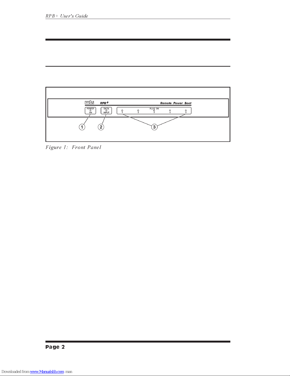
As shown in Figure 1, the RPB+ front panel includes a series of
LED indicators which function as follows:
À
POWER ON: Lights when AC Power is applied to the
RPB+.
Á
DATA INPUT: Flashes when ASCII commands are
received at the Control Port.
Â
PLUG ON (Plugs1-5): Lights when the corresponding
plug is switched On.
Page 2
RPB+ User's Guide
Figure 1: Front Panel
2.2. Back Panel
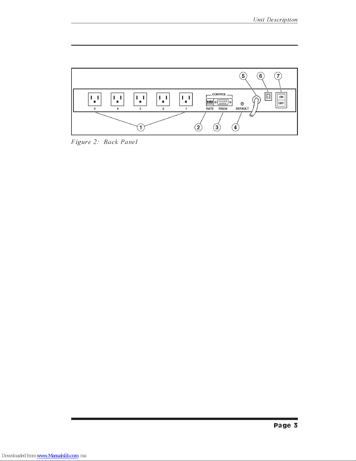
As shown in Figure 2, the RPB+ back panel includes the
following items:
À
Switched AC Outlets (Plugs1-5): For connection to up
to five AC devices. Each outlet is capable of switching up
to 15 Amps. The total for all five outlets must not exceed
15 Amps.
Á
SetUp Switches (RATE): A bank of four DIP Switches
which set the Control Port baud rate, select the Off Time
duration, enable/disable the Password Option, and
enable/disable the Read Only Mode.
Â
RS232 (Control) Port: For connection to an external
modem or local PC. The RPB+ accepts ASCII commands
via the Control Port.
Ã
DEFAULT Button: Reads Rate Switch settings and sets
parameters accordingly. This allows the user to change
Rate Switch settings without re-booting the RPB+ and
connected devices. The Default Button can also be used to
bypass the Password Prompt.
Ä
Power Cable (115 VAC Units)
Power Cable Receptacle (230 VAC Units)
Å
Circuit Breaker: 15 Amps
Æ
Power Switch
Page 3
Unit Description
Figure 2: Back Panel
 Loading...