

WTI NPS-115, NPS-230 User Manual

WTI Part No.: 12927
Rev. D
NPS Series
Network Power Switch
Models NPS-115 & NPS-230
(Firmware Version 2.04 and Higher)
User's Guide
5 Sterling · Irvine · California 92618
(949) 586-9950
Fax: (949) 583-9514
· Toll Free: 1-800-854-7226
· http://www.wti.com

Table of Contents
1. Introduction
2. Unit Description
2.1. Front Panel
2.2. Back Panel
3. Installation
3.1. Option Switches
3.2. Console Port Connection
3.3. Connecting an External Modem
3.4. Connecting the Network Cable
3.5. Power Supply Connection
3.6. Connection to Switched Outlets
3.7. Reset Unit to Defaults
3.7.1. Default Parameters Option
3.7.2. Default Button (Local)
4. Start-Up / Configuration ......................................7
4.1. System Mode and User Mode .................................7
4.2. Communicating with the NPS .................................8
4.3. NPS Command/Menu Conventions .............................10
4.4. Defining General Parameters ................................10
4.5. Plug Parameters ........................................12
4.6. Network Parameters......................................13
4.6.1. Implementing IP Security..............................14
4.7. Save Configuration Parameters ...............................15
..............................................
............................................
............................................
............................................
...............................................
.........................................
....................................
................................
................................
...................................
................................
.....................................
..............................
................................
1
2
2
3
4
4
4
5
5
5
5
5
6
6
5. Operation ...............................................16
5.1. Access the NPS Command Mode ..............................16
5.2. Displaying Plug Status
5.3. Boot/On/Off Commands
5.3.1. Applying Commands to Several Plugs
5.4. The Default Command
5.5. Other Commands
5.5.1. Login as Different User
5.5.2. Reset Network Port
5.5.3. Exit / Disconnect
5.6. Operating Tips
6. Saving and Restoring Configuration Parameters
6.1. Sending Parameters to a File
6.2. Restoring Saved Parameters
.........................................
....................................
...................................
......................
....................................
.......................................
...............................
.................................
...................................
.......................
.................................
.................................
17
18
19
19
20
20
20
20
20
21
21
22
i

NPS Series - Network Power Switches, User's Guide Table of Contents
Appendices
A. Interface Descriptions
A.1. Console Port Interface
A.2. Modem Port Interface
B. Specifications
C. Customer Service
Index
.................................................
..........................................
........................................
.....................................
..................................
..................................
Apx-1
Apx-1
Apx-1
Apx-2
Apx-3
Index-1
List of Figures
1. Front Panel
2. Back Panel (Model NPS-115 Shown)
3. System Help Screen
4. User Help Screen
..............................................
...............................
.........................................
..........................................
5. General Parameters Menu (System Mode Only)........................11
6. Plug Parameters Menu (Plug 1 Shown) .............................12
7. Network Parameters Menu (System Mode Only) .......................13
8. IP Security Menu ..........................................14
9. System Status Screen (Passwords Hidden) ...........................17
10. User Status Screen .........................................17
A.1. Console Port Interface ....................................Apx-1
A.2. Modem Port Interface .....................................Apx-1
2
3
9
9
ii

1. Introduction
Network equipment sometimes "locks-up", requiring a service call just to flip the power switch
to perform a simple reboot. The NPS Network Power Switch gives network administrators the
ability to perform this function from anywhere on the LAN/WAN, or if the network is down, to
simply dial-in from a modem for out-of-band power control.
Intelligent Power Control
The NPS can communicate over any TCP/IP network using generic Telnet, or out-of-band using
an external modem and terminal emulation. Each outlet can be assigned an individual
password, device name, reboot delay time and unique power-up default status.
Security and Co-Location Features
Address specific IP security masks prevent unauthorized network access to the NPS command
mode. The NPS provides two password security levels; System level and User level. The
System password allows access to all configuration and command functions. The User
password allows access only to assigned plugs. User level security features are ideal for colocation applications, where multiple users may be allowed plug-specific access to the NPS
unit.
Easy to Use, Easy to Configure
Reboots and plug switching are controlled by simple ASCII commands sent to the unit via
network, modem or from a local PC. Set-up and configuration is also simple; easy-to-follow
menus lead the user through the installation process.
Features:
·
Turn On/Off any AC Powered Device via Telnet, Modem or Local Terminal.
·
Eight (8) Individual Switched Outlets
·
Dual 15 Amp Circuits
·
Two Levels of Outlet Specific Password Security plus Network Security
·
115 VAC and 230 VAC Models
Typographic Conventions
Throughout this manual, typefaces and characters have been used to denote the following:
COURIER FONT Indicates characters typed on the keyboard.
For example, /ON 3 or /OFF 5.
[Bold Font] Text set in bold face and enclosed in square brackets indicates a specific
key. For example, [Enter] or [Esc].
1
2. Unit Description
2.1. Front Panel
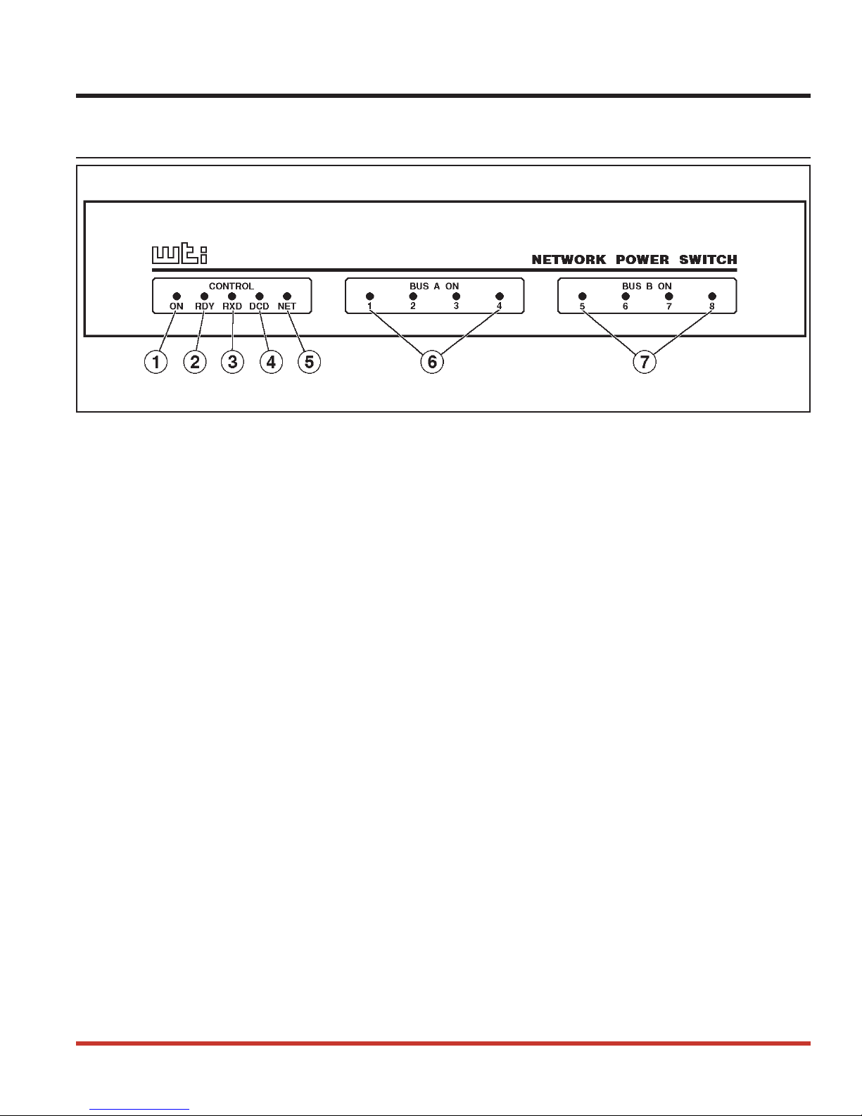
Figure 1: Front Panel
As shown in Figure 1, the NPS front panel includes a series of LED indicators which function
as follows:
ON: Lights when AC Power is applied to the NPS.
À
RDY: Flashes when the NPS is ready to receive commands.
Á
RXD: Lights when the NPS receives commands.
Â
DCD: Lights when the Modem Port detects the Carrier.
Ã
NET: Lights when a Telnet session is in progress.
Ä
Bus A Indicators (1 - 4): Light when the corresponding Plug is switched On.
Å
Bus B Indicators (5 - 8): Light when the corresponding Plug is switched On.
Æ
2
NPS Series - Network Power Switches, User's Guide Unit Description
2.2. Back Panel
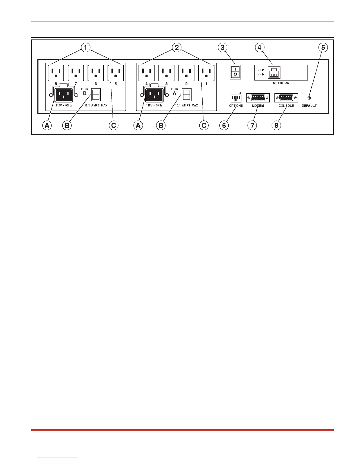
Figure 2: Back Panel (Model NPS-115 Shown)
Bus B (Plugs5-8): Includes the following components:
À
A) Power Inlet with Cable Clamp: Supplies power for plugs 5 through 8.
B) Circuit Breaker: NPS-115: 15 Amps;
NPS-230: 10 Amps
C) Switched AC Outlets (5 - 8): Each outlet can switch up to 15 Amps (NPS-115) or 10
Amps (NPS-230). The total for all four outlets must not exceed 15 Amps for NPS115, or 10 Amps for NPS-230.
Bus A (Plugs1-4): Same as Item 1 above, except the Bus A Power Inlet supplies power
Á
to plugs 1 through 4.
Master Power Switch: This switch must be in "On" in order for the NPS to function.
Â
This switch is not used to set the On/Off status of the switched outlets.
Network Port: An RJ45 Ethernet port for connection to your TCP/IP network. To
Ã
communicate via Network, you must first specify the IP Address, Subnet Mask and
Gateway Address as described in Section 4.6.
Default Button: Bypasses the password prompt as described in Section 4.2. Can also
Ä
reset unit to default settings as described in Section 3.7.
Option Switches: A bank of four DIP Switches which select default settings for the baud
Å
rate and other features.
Modem Port: A Male RS-232, DB9 Connector, DTE configuration. For connection to
Æ
an external modem.
Console Port: A Male RS-232, DB9 Connector, DTE configuration. For connection to a
Ç
local PC.
3

3. Installation
3.1. Option Switches
The Option Switches select default settings for the Baud Rate, Command Echo, Boot Delay and
Disconnect Timeout. Default settings selected via the Option Switches will be used when the
unit is reset to default parameters as described in Section 3.7.
Note: Although the Option Switches select default settings for these features, the
NPS configuration menus can also be used to select operating parameters as
described in Section 4.
Option Switch settings are described below:
Baud Rate: The default baud rate for the Console Port and Modem Port. This rate will be
selected after a power interruption, and when the unit is reset to default parameters.
Boot Delay: The default Boot Delay setting. When a boot cycle is initiated, the Boot Delay
determines the length of time that the switched outlet will remain off until power is restored.
Command Echo: The default setting for the Command Echo for the Console Port, Modem
Port and Network Port. When enabled, commands entered at your keyboard will be sent to
the NPS and echoed back to your display monitor.
Disconnect Timeout: The default Disconnect Timeout value. This determines how long the
NPS will wait for additional commands before automatically disconnecting. Note that when
the NPS times out, DTR will drop, and the modem disconnect string and initialize string will
be sent.
Switch Function Up Down
1
2
3
4
Default Baud Rate
Default Boot Delay
Default Command Echo
Default Disconnect
Timeout
38.4K bps 9600 bps*
10 Sec. 5 Sec.*
Enable Disable*
30 Min 2 Min*
* = Factory Setting
3.2. Console Port Connection
The Console Port is a male, DB9 connector, wired in a DTE configuration (similar to an AT
computer), which is used for connection to a local PC or control device. Appendix A describes
the Console Port interface.
4

NPS Series - Network Power Switches, User's Guide Installation
3.3. Connecting an External Modem
When connecting directly to an external modem, use a standard AT to Modem cable. Make
certain the modem is initialized at the same baud rate as the NPS (Option Switch 1). The
modem must be set to Auto-Answer, in one ring. Please refer to the modem user’s guide for
more information. Section 4.4 describes the procedure for defining the modem command
strings. Appendix A describes the modem port interface.
3.4. Connecting the Network Cable
The Network Port is an RJ45 Ethernet jack, for connection to a TCP/IP network. Connect your
10Base-T cable to the Network Port. Before attempting to access the unit via network, please
assign the IP Address, Gateway Address and Subnet Mask as described in Section 4.6.
3.5. Power Supply Connection
The NPS includes two AC inputs. The Bus A input provides power for plugs 1 through 4. The
Bus B input provides power for plugs 5 through 8. In order for the NPS to function, Bus A
and/or Bus B must be connected to an appropriate power supply.
3.6. Connection to Switched Outlets
The Main Power Switch must be "On" in order for the NPS to operate. When the unit is
powered On, the eight AC outlets will be switched On or Off, as specified by the user defined
Power-Up Default (see Section 4.5).
·
NPS-115: Each outlet can switch up to 15 Amps AC. The total for each Bus cannot
exceed 15 Amps.
·
NPS-230: Each outlet can switch up to 10 Amps AC, The total for each Bus cannot
exceed 10 Amps.
3.7. Reset Unit to Defaults
If Option Switch settings are changed, the new settings will not be applied until the unit is
reset to default settings. There are two ways to reset the unit to defaults:
Note: When these reset procedures are performed, all user selected parameters,
including passwords and port names will be lost. Prior to performing these reset
procedures, it is strongly recommended to save configuration parameters to an
ASCII text file as described in Section 6.
5

NPS Series - Network Power Switches, User's Guide Installation
3.7.1. Default Parameters Option
This method allows default parameters to be set without effecting the On/Off status of the
NPS's eight switched plugs. To reset the unit to default parameters, proceed as follows:
1. Access the NPS Command Mode (see Section 4.2 or 5.1).
2. At the NPS> command prompt, type /G and press [Enter]. The General Parameters
menu will appear.
3. From the General Parameters menu, type A and press [Enter]. If command confirmation
is enabled, the unit will display a prompt. Type Y and press [Enter] to proceed with the
reset procedure. After a brief pause, parameters will be reset to default values.
Note: If the Default Parameters function is invoked via the Network Port, the IP
Address will not be reset. If this function is invoked via the Console Port or
Modem Port, the IP Address will be reset.
3.7.2. Default Button (Local)
Typically, this method is used when devices have not been connected to the NPS unit, and you
have immediate access to the installation site.
Note: This method will temporarily switch all plugs Off.
Set the Master Power Switch to the OFF position. Press and hold the Default Button, located
on the instrument back panel. Place the Master Power switch in the ON position. Wait about 5
seconds, and then release the Default Button.
6
 Loading...