

Page 1

WTI Part No.: 14055
Rev.: B
AFS-16-1
Automated Fallback Switch
Quick Start Guide
Page 2
Warnings and Cautions:
Installation Instructions
Secure Racking
If Secure Racked units are installed in a closed or multi-unit rack assembly, they may require further
evaluation by Certication Agencies. The following items must be considered.
1. The ambient within the rack may be greater than room ambient. Installation should be such
that the amount of air ow required for safe operation is not compromised. The maximum
temperature for the equipment in this environment is 45°C. Consideration should be given to the
maximum rated ambient.
2. Installation should be such that a hazardous stability condition is not achieved due to uneven
loading.
Input Supply
Check nameplate ratings to assure there is no overloading of supply circuits that could have an eect
on overcurrent protection and supply wiring.
Grounding
Reliable earthing of this equipment must be maintained. Particular attention should be given to
supply connections when connecting to power strips, rather than direct connections to the branch
circuit.
No Serviceable Parts Inside; Authorized Service Personnel Only
Do not attempt to repair or service this device yourself. Internal components must be serviced by
authorized personnel only.
• ShockHazard-DoNotEnter
Two Power Supply Cables
Note that the AFS-16-1 features two separate power inputs, and a separate power supply cable for
each power input. Make certain to disconnect both power supply cables from their power source
before attempting to service or remove the unit.
Disconnect Power
If any of the following events are noted, immediately disconnect the unit from the outlet and contact
qualied service personnel:
1. If the power cord becomes frayed or damaged.
2. If liquid has been spilled into the device or if the device has been exposed to rain or water.
Page 3
Page 3
1. Introduction
This Quick Start Guide describes a simplied installation procedure for the AFS-16-1
hardware, which will allow you to communicate with the unit in order to demonstrate
basic features and check for proper operation.
Note that this Quick Start Guide does not provide a detailed
description of unit conguration, or discuss advanced operating
features in detail. For more information, please refer to the
AFS-16-1 User’s Guide, which can be found on our web site at
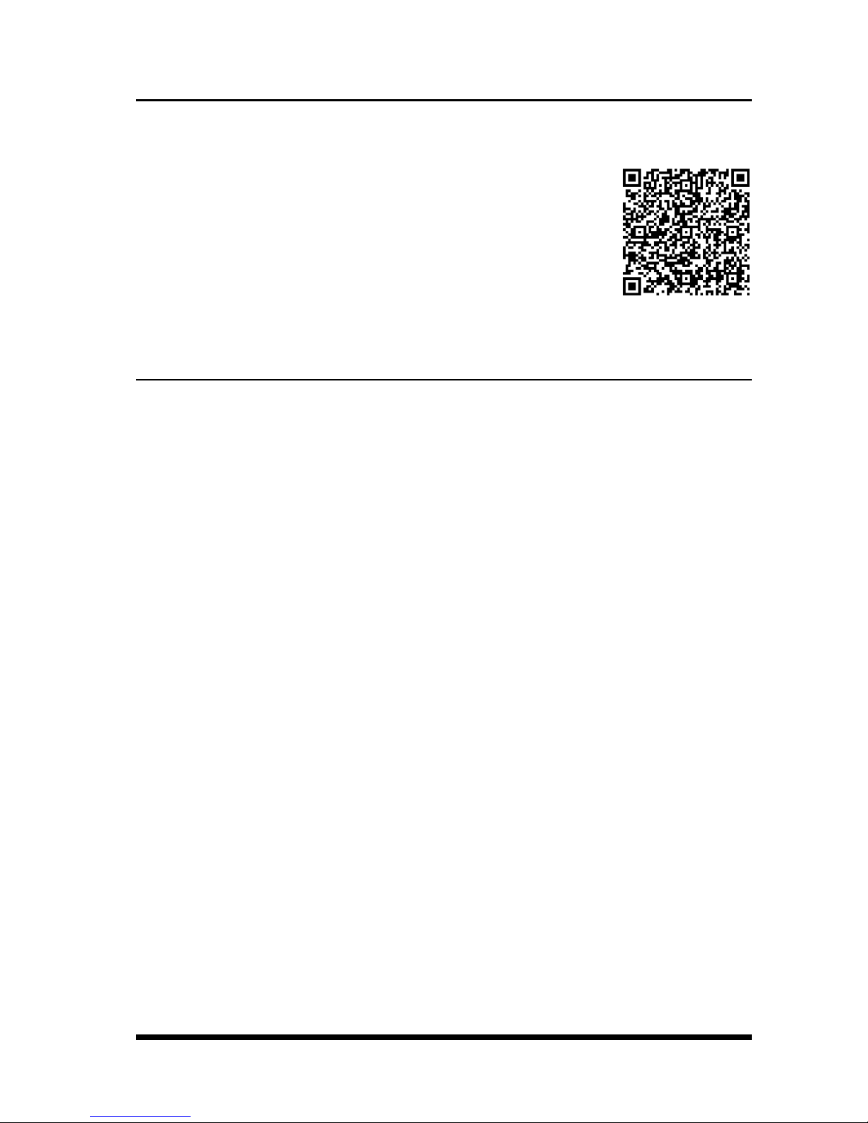
the address below, or by scanning the QR Code to the right.
http://www.wti.com/uguides
2. Hardware Installation
2.1. Apply Power to the AFS-16-1
Refer to the safety precautions listed at the beginning of this User’s Guide, and then
connect the unit to a 100 to 240 VAC power source. Connect the power supply
cables to the unit’s power inlets and then connect the cables to appropriate power
supplies.
Set the Power Switch on the AFS-16-1 Power Module to the ON Position. The ON
LED on the Power Module and the A/B indicators on the Control Module should
light. After about 90 seconds, the A/B indicators should go out, indicating that the
unit is ready to receive commands.
2.2. Connect Your PC to the AFS-16-1
The AFS-16-1 can either be controlled by a local PC Serial Port, controlled via
optional external modem, or controlled via TCP/IP network. In order to select
parameters or control switching functions, commands are issued to the AFS-16-1 via
either the Ethernet Port or RS232 Console Port.
• EthernetPort: Connect your 10Base-T or 100Base-T network interface to the
AFS-16-1 Control Module 10/100Base-T Network Port.
• RS232Port: Use the supplied Ethernet cable and adapter to connect your PC
COM port to the RS232 Console Port on the AFS Control Module as described
in the User's Guide. For a description of the RS232 Port Interface, please refer
to the User's Guide.
• Modem: If desired, an optional external modem can also be installed at the
RS232 Port. For more information, please refer to the User's Guide.
Page 4

Page 4
AFS-16: Automatic Fallback Switch; Quick Start Guide
3. Communicating with the AFS-16-1
When properly installed and congured, the AFS-16-1 will allow command mode
access via Telnet, Web Browser, SSH client, modem, or local PC. However, in order
to ensure security, both Telnet and Web Browser access are disabled in the default
state. To enable Telnet and/or Web Browser access, please refer to the User's Guide.
Notes:
• Default AFS-16-1 serial port parameters are set as follows: 9600 bps,
RTS/CTS Handshaking, 8 Data Bits, One Stop Bit, No Parity. Although
these parameters can be easily redened, for this Quick Start procedure, it
is recommended to congure your communications program to accept the
default parameters.
• The AFS-16-1 features a default IP Address (192.168.168.168) and a
default Subnet Mask (255.255.255.0.) This allows network access to
command mode, providing that you are contacting the AFS-16-1 from a
node on the same subnet. When attempting to access the AFS-16-1 from
a node that is not on the same subnet, please refer to the User's Guide for
further conguration instructions.
1. AccessCommandMode: The AFS-16-1 includes two separate user interfaces;
the Text Interface and the Web Browser Interface. The Text Interface is
available via Local PC, SSH Client, Telnet, or Modem and can be used to
both congure the AFS-16-1 and create connections between ports. The Web
Browser interface is only available via TCP/IP network, and can be used to
congure the unit, but cannot create connections between ports.
a) ViaLocalPC: Start your communications program and then
press [Enter].
b) ViaSSHClient: Start your SSH client, enter the default IP address
(192.168.168.168) for the AFS-16-1 and then invoke the connect
command.
c) ViaWebBrowser: Make certain that Web Browser access is enabled as
described in the User's Guide. Start your JavaScript enabled Web Browser,
enter the default AFS-16-1 IP address (192.169.168.168) in the Web
Browser address bar, and then press [Enter].
d) ViaTelnet: Make certain that Telnet access is enabled as described in the
User's Guide. Start your Telnet client, and enter the AFS-16-1’s default IP
address (192.168.168.168).
e) ViaModem: Use your communications program to dial the number for
the external modem (optional) that you have connected to the AFS-16-1’s
RS232 port. For more information on connecting a modem, please refer to
the User's Guide.
Page 5

Page 5
AFS-16: Automatic Fallback Switch; Quick Start Guide
2. Username/PasswordPrompt: A message will be displayed, which prompts
you to enter your username (Login) and password. The default username is
"super" (all lower case, no quotes), and the default password is also "super".
If a valid username and password are entered, the AFS-16-1 will display either
the Main Menu (Web Browser Interface) or the Circuit Status Screen (SSH,
Telnet, or Modem.)
3. ReviewHelpMenu: If you are communicating with the AFS-16-1 via the text
interface (SSH, Telnet or Modem), type /H and press [Enter] to display the
Help Menu, which lists all available AFS-16-1 commands. Note that the Help
Menu is not available via the Web Browser Interface.
3.4. Fallback Switching
A/B fallback switching can be controlled via the Text Interface or via the Web
Browser Interface.
3.4.1. Fallback Switching - Text Interface
Access the Text Interface as described in Section 3 in this Quick Start Guide and then
proceed as follows:
1. ManualA/BSwitching: Use the manual circuit switches to change A/B paths.
Note that this example assumes that the Master A/B Gang Switch and individual
circuit module switches have not been disabled.
a) MasterA/BGangSwitch: Toggle the Master A/B Gang Switch between
the "A" and "B" positions. The LED indicators should follow the Master
Switch, indicating that each circuit has switched the "A" and "B" paths.
b) CircuitModuleA/BSwitch: Choose an individual Circuit Module
and toggle the module’s A/B Switch between "A" and "B". The LED
indicators should indicate that the module has switched the A/B path.
3. CodeActivatedSwitching: To control A/B fallback switching using ASCII
commands, invoke the following commands at the AFS command prompt:
a) Type /T *,B and press [Enter]. All Circuit Modules should switch to
the "B" path.
b) Type /T 1,A and press [Enter]. Circuit Module number 1 should switch
to the "A" path.
c) Type /T 2,3,4,A and press [Enter]. Circuit Modules 2, 3, and 4
should switch to the "A" path.
4. ExitCommandMode: To exit command mode, type /X and press [Enter].
Page 6

Page 6
AFS-16: Automatic Fallback Switch; Quick Start Guide
3.4.2. Fallback Switching - Web Browser Interface
The Web Browser Interface will not be available until you have enabled Web Access
as described in the User's Guide. After Web Access has been enabled, access the
AFS-16-1 Web Browser Interface as described in Section 3 in this Quick Start Guide
and proceed as follows:
1. AccesstheCircuitControlMenu: Click on the "Circuit Control" link on the
left hand side of the screen to display the Circuit Control menu. The Circuit
Control menu includes a series of dropdown menus that are used to select the
desired switching action for each Circuit Module.
2. SelecttheSwitchingAction: Use the dropdown menu to select an A/B
switching operation for the desired Circuit Module. For example, to switch
Circuit 1 to the B position, click on the down arrow in the "Action" column
for Circuit 1 to display the dropdown menu, select the "B" option from the
dropdown menu and then click on the "Conrm Circuit Actions" button.
Notes:
• The dropdown menu for each circuit allows you to select position A,
position B or the default position. Normally, the "Default" option will
switch the circuit to the user-dened Default position which can be
selected as described in the User's Guide. However, in the case of this
Quick Start procedure, the Default circuit positions have not yet been
dened.
• The Circuit Control Menu also includes the ability to switch all AFS-16-1
Circuit Modules. If desired, the dropdown menu in the "All Circuits" row
can be used to switch all AFS-16-1 circuits.
3. ConrmSwitchingActions: After you click on the "Conrm Circuit Actions"
button, the AFS-16-1 will display a screen which summarizes the selected
switching operation(s) and asks for conrmation before executing the command.
To proceed with the selected switching operation, click on the "Execute Circuit
Actions" button.
4. The AFS-16-1 will execute the switching operation and then display the Circuit
Status screen.
5. ExitCommandMode: Click on the "LogOut" button on the left hand side of
the screen to exit command mode.
This completes the Quick Start procedure for the AFS-16-1. Prior to placing the
unit into operation, it is recommended to refer to the AFS-16-1 User’s Guide for
important information regarding advanced conguration capabilities and more
detailed operation instructions. If you have further questions, please contact WTI
Customer Support as described in Appendix C in the User's Guide.
Page 7

Page 7
AFS-16: Automatic Fallback Switch; Quick Start Guide
Page 8

western
telematic
inc.
TM
5 Sterling • Irvine • California 92618
(949) 586-9950 • Toll Free: 1-800-854-7226
Fax: (949) 583-9514 • http://www.wti.com
 Loading...