

Page 1

W&T
PC cards for ISA bus systems
Subject to error and alteration
Manual
PC Cards for ISA Bus Systems
Type13001, 13401
13601, 13801, 13802
Release 1.2
W&T
Page 2

W&T
PC cards for ISA bus systems
© 09/2002 by Wiesemann & Theis GmbH
Subject to error and alteration:
Since it is possible that we make mistakes, you mustn’t use any
of our statements without verification. Please, inform us of any
error or misunderstanding you come about, so we can identify
and eliminate it as soon as possible.
Carry out your work on or with W&T products only to the extent that they are described here and after you have completely
read and understood the manual or guide. We are not liable for
unauthorized repairs or tampering. When in doubt, check first
with us or with your dealer.
Page 3

- 20 -
W&T
WWW.WuT.DE
Manual
W&T PC cards
Part.-No. Page
2 x RS232, without isolation 13801 21
2 x RS232, 1 kV isolated 13802 23
2 x 20mA, 1 kV isolated 13401 27
2 x RS422/485, 1 kV isolated 13601 31
2 x serial PC card, 1 kV isolated 13001 36
module mainboard
Page 4
- 21 -
W&T
WWW.WuT.DE
Function
The W&T PC card 13801 equip your PC with two independent RS232 serial interfaces.
Both serial ports are equipped with type 16C550 FIFO UARTs; this makes them functionally compatible with
standard RS232 interfaces, so that the cards can easily be used with your available software. Following a reset, the
type 16550 elements are in standard UART operating mode, so that there is no need to worry about existing
software. The FIFO mode has to be activated explicitly by the software.
DMA operation of the 16550 UARTs is not supported by the hardware of the W&T PC card 13801.
ESD protection
All interface signal lines of the PC card 13801 are protected against electrostatic discharge of up to 15 kV according
to IEC 801-2, level 4.
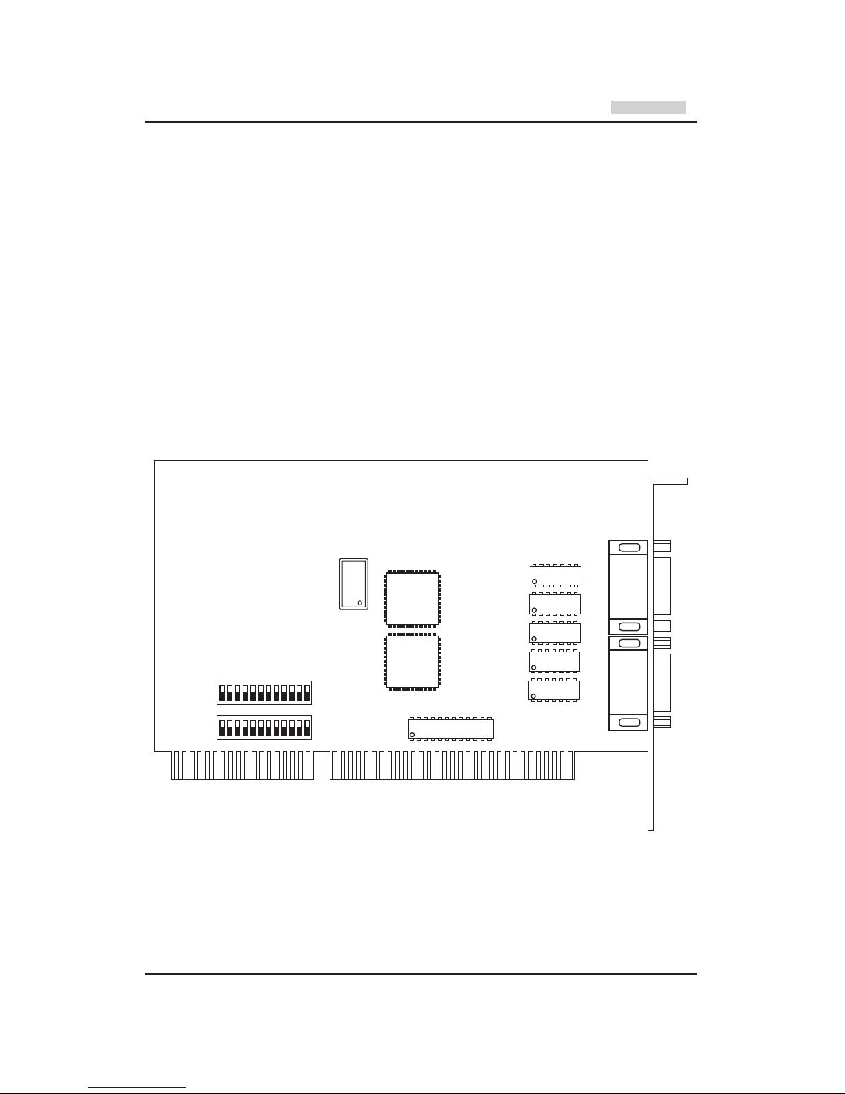
Configuring the card
The base address and the required interrupt line can be set by DIP switches at the lower edge of the card.
Port 2 Port 1
20V8
SW1
SW2
UART
Port 2
UART
Port 1
XTAL
PC card 2 x RS232
#13801
Page 5
- 22 -
W&T
WWW.WuT.DE
Base addresses
The I/O base addresses of the two ports can be set independently by DIP switches to 03F8H, 02F8H, 03E8H or
02E8H. Serial ports at these base addresses are recognized by almost all modern BIOS versions upon startup of
the PC, and are written to the BIOS RAM of the computer. Some older BIOS versions recognize only two serial ports
at the base addresses for COM1 and COM2. In these rare cases, a separate program is needed to search the
computer for installed serial ports and write the COM3 and COM4 ports to BIOS RAM. The necessary software can
be obtained from W&T on request. Setting both ports to the same base address should be strictly avoided. Please
see the following tables for an explanation of the address DIP switch settings:
Since the address is decoded by means of GALs, customizing of the I/O address is no problem. This option makes
it possible to employ more than 4 serial ports on a computer, if the software permits the use of additional I/O
addresses.
Interrupt settings
The W&T serial PC Cards permit use of the standard interrupts IRQ3 and IRQ4 for the serial ports COM1 and
COM2, and interrupts IRQ5 and IRQ7 for the parallel ports LPT1 and LPT2 if the system has no parallel ports or if
the built-in parallel ports do not operate in interrupt mode. Since it is a long card, the PC Card 16201 also supports
interrupts IRQ9..IRQ12 of the second interrupt controller. Please see the following tables for an explanation of the
IRQ DIP switch setting:
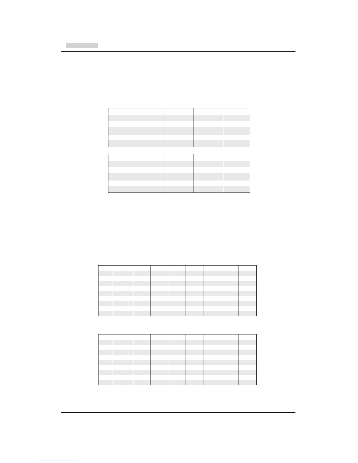
Interrupt setting port 1
Interrupt setting port 2
Port 1 SW 1.9 SW 1.10 SW 1.11
Disabled X X OFF
COM1 03F8H OFF OFF ON
COM2 02F8H ON OFF ON
COM3 03E8H OFF ON ON
COM4 02E8H ON ON ON
Port 2 SW 2.9 SW 2.10 SW 2.11
Disabled X X OFF
COM1 03F8H OFF OFF ON
COM2 02F8H ON OFF ON
COM3 03E8H OFF ON ON
COM4 02E8H ON ON ON
IRQ SW 1.1 SW 1.2 SW 1.3 SW 1.4 SW 1.5 SW 1.6 SW 1.7 SW 1.8
- OFF OFF OFF OFF OFF OFF OFF OFF
3 OFF OFF OFF ON OFF OFF OFF OFF
4 OFF OFF OFF OFF ON OFF OFF OFF
5 OFF OFF OFF OFF OFF ON OFF OFF
7 OFF OFF OFF OFF OFF OFF ON OFF
9 OFF OFF OFF OFF OFF OFF OFF ON
10 OFF OFF ON OFF OFF OFF OFF OFF
11 OFF ON OFF OFF OFF OFF OFF OFF
12 ON OFF OFF OFF OFF OFF OFF OFF
IRQ SW 2.1 SW 2.2 SW 2.3 SW 2.4 SW 2.5 SW 2.6 SW 2.7 SW 2.8
- OFF OFF OFF OFF OFF OFF OFF OFF
3 OFF OFF OFF ON OFF OFF OFF OFF
4 OFF OFF OFF OFF ON OFF OFF OFF
5 OFF OFF OFF OFF OFF ON OFF OFF
7 OFF OFF OFF OFF OFF OFF ON OFF
9 OFF OFF OFF OFF OFF OFF OFF ON
10 OFF OFF ON OFF OFF OFF OFF OFF
11 OFF ON OFF OFF OFF OFF OFF OFF
12 ON OFF OFF OFF OFF OFF OFF OFF
SW 2.12 has
no function
SW 1.12 has
no function
PC card 2 x RS232
#13801
Page 6

- 23 -
W&T
WWW.WuT.DE
Connectors and pin assignment
The two ports of the W&T RS232 PC card 13801 use DB9 male connectors with identical pin configuration. The
connector pin assignments are shown in the table below:
Technical data
base adresses: 03F8H, 02F8H, 03E8H, 02E8H
interrupts: IRQ3, IRQ4, IRQ5, IRQ7
IRQ9, IRQ10, IRQ11, IRQ12
Baudrate: 50..115200 Baud
data format: any data format
insulation: no insulation
ESD protection: up to 15 kV according to IEC 801-2, level 4
supply current: approx. 200mA @5V, 30mA @12V, 30mA @-12V
RS232 interface: DB 9 male connector
dimensions: 165 x 106 mm
weight: approx. 150 g
packing list: 1 x RS232 PC card, type 13801
function
DCD
RxD
TxD
DTR
GND
DSR
RTS
CTS
RI
pin#
1
2
3
4
5
6
7
8
9
pin assignment
RS232 interface
PC card 2 x RS232
#13801
Page 7

- 24 -
W&T
WWW.WuT.DE
PC card 2 x RS232
#13802
Function
The W&T PC card 13802 equip your PC with two independent RS232 serial interfaces with an insulation of up to
1000 Volts.
Both serial ports are equipped with type 16C550 FIFO UARTs; this makes them functionally compatible with
standard RS232 interfaces, so that the cards can easily be used with your available software. Following a reset, the
type 16550 elements are in standard UART operating mode, so that there is no need to worry about existing
software. The FIFO mode has to be activated explicitly by the software.
DMA operation of the 16550 UARTs is not supported by the hardware of the W&T port cards.
Insulation and ESD protection
The two ports of the W&T serial PC card 13802 are insulated both from each other and from the PC with a dielectric
strength of 1000 volts. The signals are isolated by means of high-speed opto-couplers; energy is supplied to the
driver and receiver elements by means of an isolated DC/DC converter. Please note that the shielding of the port
connectors is directly connected to the case of the PC by the metallic back panel.
All interface signal lines of the PC card 13802 are protected against electrostatic discharge of up to 15 kV according
to IEC 801-2, level 4.
Configuring the card
The base address and the required interrupt line can be set by DIP switches at the lower edge of the card.
Port 2 Port 1
20V8
SW1
SW2
UART
Port 2
UART
Port 1
XTAL
Page 8
- 25 -
W&T
WWW.WuT.DE
Base addresses
The I/O base addresses of the two ports can be set independently by DIP switches to 03F8H, 02F8H, 03E8H or
02E8H. Serial ports at these base addresses are recognized by almost all modern BIOS versions upon startup of
the PC, and are written to the BIOS RAM of the computer. Some older BIOS versions recognize only two serial ports
at the base addresses for COM1 and COM2. In these rare cases, a separate program is needed to search the
computer for installed serial ports and write the COM3 and COM4 ports to BIOS RAM. The necessary software can
be obtained from W&T on request. Setting both ports to the same base address should be strictly avoided. Please
see the following tables for an explanation of the address DIP switch settings:
Since the address is decoded by means of GALs, customizing of the I/O address is no problem. This option makes
it possible to employ more than 4 serial ports on a computer, if the software permits the use of additional I/O
addresses.
Interrupt settings
The W&T serial PC Cards permit use of the standard interrupts IRQ3 and IRQ4 for the serial ports COM1 and
COM2, and interrupts IRQ5 and IRQ7 for the parallel ports LPT1 and LPT2 if the system has no parallel ports or if
the built-in parallel ports do not operate in interrupt mode. Since it is a long card, the PC Card 16201 also supports
interrupts IRQ9..IRQ12 of the second interrupt controller. Please see the following tables for an explanation of the
IRQ DIP switch setting:
Interrupt setting port 1
Interrupt setting port 2
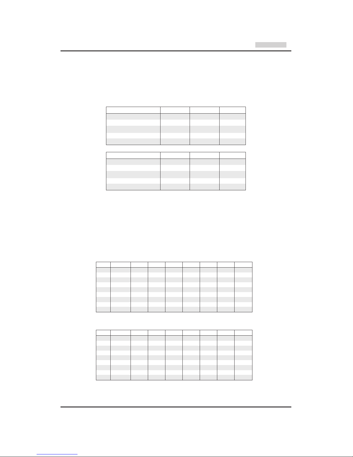
Port 1 SW 1.9 SW 1.10 SW 1.11
Disabled X X OFF
COM1 03F8H OFF OFF ON
COM2 02F8H ON OFF ON
COM3 03E8H OFF ON ON
COM4 02E8H ON ON ON
Port 2 SW 2.9 SW 2.10 SW 2.11
Disabled X X OFF
COM1 03F8H OFF OFF ON
COM2 02F8H ON OFF ON
COM3 03E8H OFF ON ON
COM4 02E8H ON ON ON
IRQ SW 1.1 SW 1.2 SW 1.3 SW 1.4 SW 1.5 SW 1.6 SW 1.7 SW 1.8
- OFF OFF OFF OFF OFF OFF OFF OFF
3 OFF OFF OFF ON OFF OFF OFF OFF
4 OFF OFF OFF OFF ON OFF OFF OFF
5 OFF OFF OFF OFF OFF ON OFF OFF
7 OFF OFF OFF OFF OFF OFF ON OFF
9 OFF OFF OFF OFF OFF OFF OFF ON
10 OFF OFF ON OFF OFF OFF OFF OFF
11 OFF ON OFF OFF OFF OFF OFF OFF
12 ON OFF OFF OFF OFF OFF OFF OFF
IRQ SW 2.1 SW 2.2 SW 2.3 SW 2.4 SW 2.5 SW 2.6 SW 2.7 SW 2.8
- OFF OFF OFF OFF OFF OFF OFF OFF
3 OFF OFF OFF ON OFF OFF OFF OFF
4 OFF OFF OFF OFF ON OFF OFF OFF
5 OFF OFF OFF OFF OFF ON OFF OFF
7 OFF OFF OFF OFF OFF OFF ON OFF
9 OFF OFF OFF OFF OFF OFF OFF ON
10 OFF OFF ON OFF OFF OFF OFF OFF
11 OFF ON OFF OFF OFF OFF OFF OFF
12 ON OFF OFF OFF OFF OFF OFF OFF
SW 2.12 has
no function
SW 1.12 has
no function
PC card 2 x RS232
#13802
Page 9

- 26 -
W&T
WWW.WuT.DE
PC card 2 x RS232
#13802
Connectors and pin assignment
The two ports of the W&T RS232 PC card 13802 use DB9 male connectors with identical pin configuration. The
connector pin assignments are shown in the table below:
Technical data
base adresses: 03F8H, 02F8H, 03E8H, 02E8H
interrupts: IRQ3, IRQ4, IRQ5, IRQ7
IRQ9, IRQ10, IRQ11, IRQ12
Baudrate: 50..115200 Baud
data format: any data format
insulation: min. 1000 volts
ESD protection: up to 15 kV according to IEC 801-2, level 4
supply current: approx. 200mA @5V, 80mA @12V
RS232 interface: DB 9 male connector
dimensions: 165 x 106 mm
weight: approx. 200 g
packing list: 1 x RS232 PC card, type 13802
function
DCD
RxD
TxD
DTR
GND
DSR
RTS
CTS
RI
pin#
1
2
3
4
5
6
7
8
9
pin assignment
RS232 interface
Page 10
- 27 -
W&T
WWW.WuT.DE
Function
The W&T PC card 13401 equip your PC with two independent 20mA serial interfaces with an insulation of up to
1000 Volts.
Both serial ports are equipped with type 16C550 FIFO UARTs; this makes them functionally compatible with
standard RS232 interfaces, so that the cards can easily be used with your available software. Following a reset, the
type 16550 elements are in standard UART operating mode, so that there is no need to worry about existing
software. The FIFO mode has to be activated explicitly by the software.
DMA operation of the 16550 UARTs is not supported by the hardware of the W&T port cards.
Insulation and ESD protection
The two ports of the W&T serial PC card 13401 are insulated both from each other and from the PC with a dielectric
strength of 1000 volts. The signals are isolated by means of high-speed opto-couplers; energy is supplied to the
driver and receiver elements by means of an isolated DC/DC converter. Please note that the shielding of the port
connectors is directly connected to the case of the PC by the metallic back panel.
All interface signal lines of the PC card 13401 are protected against electrostatic discharge of up to 15 kV according
to IEC 801-2, level 4.
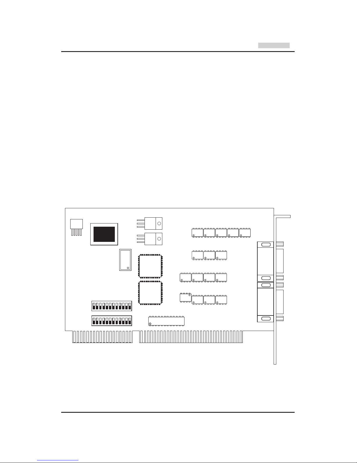
Configuring the card
The base address and the required interrupt line can be set by DIP switches at the lower edge of the card.
Port 2 Port 1
20V8
SW1
SW2
UART
Port 2
UART
Port 1
XTAL
PC card 2 x 20mA
#13401
Page 11
- 28 -
W&T
WWW.WuT.DE
Base addresses
The I/O base addresses of the two ports can be set independently by DIP switches to 03F8H, 02F8H, 03E8H or
02E8H. Serial ports at these base addresses are recognized by almost all modern BIOS versions upon startup of
the PC, and are written to the BIOS RAM of the computer. Some older BIOS versions recognize only two serial ports
at the base addresses for COM1 and COM2. In these rare cases, a separate program is needed to search the
computer for installed serial ports and write the COM3 and COM4 ports to BIOS RAM. The necessary software can
be obtained from W&T on request. Setting both ports to the same base address should be strictly avoided. Please
see the following tables for an explanation of the address DIP switch settings:
Since the address is decoded by means of GALs, customizing of the I/O address is no problem. This option makes
it possible to employ more than 4 serial ports on a computer, if the software permits the use of additional I/O
addresses.
Interrupt settings
The W&T serial PC Cards permit use of the standard interrupts IRQ3 and IRQ4 for the serial ports COM1 and
COM2, and interrupts IRQ5 and IRQ7 for the parallel ports LPT1 and LPT2 if the system has no parallel ports or if
the built-in parallel ports do not operate in interrupt mode. Since it is a long card, the PC Card 16201 also supports
interrupts IRQ9..IRQ12 of the second interrupt controller. Please see the following tables for an explanation of the
IRQ DIP switch setting:
Interrupt setting port 1
Interrupt setting port 2
Port 1 SW 1.9 SW 1.10 SW 1.11
Disabled X X OFF
COM1 03F8H OFF OFF ON
COM2 02F8H ON OFF ON
COM3 03E8H OFF ON ON
COM4 02E8H ON ON ON
Port 2 SW 2.9 SW 2.10 SW 2.11
Disabled X X OFF
COM1 03F8H OFF OFF ON
COM2 02F8H ON OFF ON
COM3 03E8H OFF ON ON
COM4 02E8H ON ON ON
IRQ SW 1.1 SW 1.2 SW 1.3 SW 1.4 SW 1.5 SW 1.6 SW 1.7 SW 1.8
- OFF OFF OFF OFF OFF OFF OFF OFF
3 OFF OFF OFF ON OFF OFF OFF OFF
4 OFF OFF OFF OFF ON OFF OFF OFF
5 OFF OFF OFF OFF OFF ON OFF OFF
7 OFF OFF OFF OFF OFF OFF ON OFF
9 OFF OFF OFF OFF OFF OFF OFF ON
10 OFF OFF ON OFF OFF OFF OFF OFF
11 OFF ON OFF OFF OFF OFF OFF OFF
12 ON OFF OFF OFF OFF OFF OFF OFF
IRQ SW 2.1 SW 2.2 SW 2.3 SW 2.4 SW 2.5 SW 2.6 SW 2.7 SW 2.8
- OFF OFF OFF OFF OFF OFF OFF OFF
3 OFF OFF OFF ON OFF OFF OFF OFF
4 OFF OFF OFF OFF ON OFF OFF OFF
5 OFF OFF OFF OFF OFF ON OFF OFF
7 OFF OFF OFF OFF OFF OFF ON OFF
9 OFF OFF OFF OFF OFF OFF OFF ON
10 OFF OFF ON OFF OFF OFF OFF OFF
11 OFF ON OFF OFF OFF OFF OFF OFF
12 ON OFF OFF OFF OFF OFF OFF OFF
SW 2.12 has
no function
SW 1.12 has
no function
PC card 2 x 20mA
#13401
Page 12
- 29 -
W&T
WWW.WuT.DE
PC card 2 x 20mA
#13401
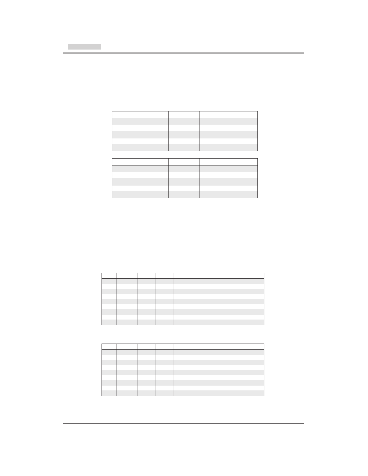
Connectors and pin assignment
The two ports of the W&T 20 mA PC card 13401 use DB9 male connectors with identical pin configuration. The
connector pin assignments are shown in the table below:
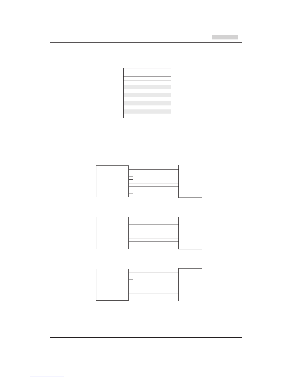
Applications
The PC card 13401 can be used as an active or passive 20mA component. In the active mode, the card supplies
the current required by the respective 20mA loop, while in the passive mode the loop current must be supplied by
the connected device. The operating mode can be selected for both loops separately. Examples of card-switching
into active/passive mode are shown in the following drawings:
RxD +
RxD -
TxD +
TxD -
active / passive
20mA device
Active Tx and passive Rx current loop application
20mA interface
PC with 13401
1
2
3
4
6
7
8
9
Data Out 20mA
Data Out+
Data Out -
Data Out GND
Data In 20mA
Data In+
Data In -
Data In GND
RxD +
RxD -
TxD +
TxD -
active
20mA device
Passive Tx and passive Rx current loop application
20mA interface
PC with 13401
1
2
3
4
6
7
8
9
Data Out 20mA
Data Out+
Data Out -
Data Out GND
Data In 20mA
Data In+
Data In -
Data In GND
RxD +
RxD -
TxD +
TxD -
passive
20mA device
Active Tx and active Rx current loop application
20mA interface
PC with 13401
1
2
3
4
6
7
8
9
Data Out 20mA
Data Out+
Data Out -
Data Out GND
Data In 20mA
Data In+
Data In -
Data In GND
function
Data Out 20 mA
Data Out +
Data Out Data Out GND
n.c.
Data In 20 mA
Data In +
Data In Data In GND
pin#
1
2
3
4
5
6
7
8
9
pin assignment
20mA interface
Page 13

- 30 -
W&T
WWW.WuT.DE
Technical data
base adresses: 03F8H, 02F8H, 03E8H, 02E8H
interrupts: IRQ3, IRQ4, IRQ5, IRQ7
IRQ9, IRQ10, IRQ11, IRQ12
baudrate: 50..57600 Baud
data format: any data format
operation modes: 20mA active mode / 20mA passive mode
independently selectable for Tx and Rx current loop
insulation: min. 1000 volts
ESD protection: up to 15 kV according to IEC 801-2, level 4
supply current: approx. 200mA @5V, 60mA @12V
20mA interface: DB9 male connector
dimensions: 165 x 106 mm
weight: approx. 200 g
packing list: 1 x 20mA PC card, type 13401
PC card 2 x 20mA
#13401
Page 14

- 31 -
W&T
WWW.WuT.DE
Function
The W&T PC card 13601 equip your PC with two independent RS422/RS485 serial interfaces with an insulation of
up to 1000 Volts.
Both serial ports are equipped with type 16C550 FIFO UARTs; this makes them functionally compatible with
standard RS232 interfaces, so that the cards can easily be used with your available software. Following a reset, the
type 16550 elements are in standard UART operating mode, so that there is no need to worry about existing
software. The FIFO mode has to be activated explicitly by the software.
DMA operation of the 16550 UARTs is not supported by the hardware of the W&T port cards.
Insulation and ESD protection
The two ports of the W&T serial PC card 13601 are insulated both from each other and from the PC with a dielectric
strength of 1000 volts. The signals are isolated by means of high-speed opto-couplers; energy is supplied to the
driver and receiver elements by means of an isolated DC/DC converter. Please note that the shielding of the port
connectors is directly connected to the case of the PC by the metallic back panel.
All interface signal lines of the PC card 13601 are protected against electrostatic discharge of up to 15 kV according
to IEC 801-2, level 4.
Configuring the card
The base address and the required interrupt line can be set by DIP switches at the lower edge of the card.
Port 2 Port 1
20V8
SW1
SW2
UART
Port 2
UART
Port 1
XTAL
PC card 2 x RS422/485
#13601
Page 15

- 32 -
W&T
WWW.WuT.DE
Base addresses
The I/O base addresses of the two ports can be set independently by DIP switches to 03F8H, 02F8H, 03E8H or
02E8H. Serial ports at these base addresses are recognized by almost all modern BIOS versions upon startup of
the PC, and are written to the BIOS RAM of the computer. Some older BIOS versions recognize only two serial ports
at the base addresses for COM1 and COM2. In these rare cases, a separate program is needed to search the
computer for installed serial ports and write the COM3 and COM4 ports to BIOS RAM. The necessary software can
be obtained from W&T on request. Setting both ports to the same base address should be strictly avoided. Please
see the following tables for an explanation of the address DIP switch settings:
Since the address is decoded by means of GALs, customizing of the I/O address is no problem. This option makes
it possible to employ more than 4 serial ports on a computer, if the software permits the use of additional I/O
addresses.
Interrupt settings
The W&T serial PC Cards permit use of the standard interrupts IRQ3 and IRQ4 for the serial ports COM1 and
COM2, and interrupts IRQ5 and IRQ7 for the parallel ports LPT1 and LPT2 if the system has no parallel ports or if
the built-in parallel ports do not operate in interrupt mode. Since it is a long card, the PC Card 16201 also supports
interrupts IRQ9..IRQ12 of the second interrupt controller. Please see the following tables for an explanation of the
IRQ DIP switch setting:
Interrupt setting port 1
Interrupt setting port 2
PC card 2 x RS422/485
#13601
Port 1 SW 1.9 SW 1.10 SW 1.11
Disabled X X OFF
COM1 03F8H OFF OFF ON
COM2 02F8H ON OFF ON
COM3 03E8H OFF ON ON
COM4 02E8H ON ON ON
Port 2 SW 2.9 SW 2.10 SW 2.11
Disabled X X OFF
COM1 03F8H OFF OFF ON
COM2 02F8H ON OFF ON
COM3 03E8H OFF ON ON
COM4 02E8H ON ON ON
SW 2.12 has
no function
SW 1.12 has
no function
IRQ SW 1.1 SW 1.2 SW 1.3 SW 1.4 SW 1.5 SW 1.6 SW 1.7 SW 1.8
- OFF OFF OFF OFF OFF OFF OFF OFF
3 OFF OFF OFF ON OFF OFF OFF OFF
4 OFF OFF OFF OFF ON OFF OFF OFF
5 OFF OFF OFF OFF OFF ON OFF OFF
7 OFF OFF OFF OFF OFF OFF ON OFF
9 OFF OFF OFF OFF OFF OFF OFF ON
10 OFF OFF ON OFF OFF OFF OFF OFF
11 OFF ON OFF OFF OFF OFF OFF OFF
12 ON OFF OFF OFF OFF OFF OFF OFF
IRQ SW 2.1 SW 2.2 SW 2.3 SW 2.4 SW 2.5 SW 2.6 SW 2.7 SW 2.8
- OFF OFF OFF OFF OFF OFF OFF OFF
3 OFF OFF OFF ON OFF OFF OFF OFF
4 OFF OFF OFF OFF ON OFF OFF OFF
5 OFF OFF OFF OFF OFF ON OFF OFF
7 OFF OFF OFF OFF OFF OFF ON OFF
9 OFF OFF OFF OFF OFF OFF OFF ON
10 OFF OFF ON OFF OFF OFF OFF OFF
11 OFF ON OFF OFF OFF OFF OFF OFF
12 ON OFF OFF OFF OFF OFF OFF OFF
Page 16

- 33 -
W&T
WWW.WuT.DE
Connectors and pin assignment
The two ports of the W&T RS422/RS485 PC card 13601 use DB9 male connectors with identical pin configuration.
The connector pin assignments are shown in the table below:
Operating mode
The RS422/RS485 interface of the W&T PC card 13601 can be set for five different operating modes by DIP switch
setting. The selectable operating modes are briefly described here:
RS422, RS485 4 wire bus master application
One data channel and one handshake channel in each direction are available. The RS422/RS485 receivers and
transmitters are always active in this operating mode.
RS485 4-wire application / RS485 2-wire application with echo, handshake control
One data channel in each direction is available. The RS485 output driver is switched on with DTR or RTS = “ON”,
while DTR or RTS = “OFF” forces the driver to high impedance state. The RS485 receiving channel is always active
in this operating mode.
RS485, 2 wire application without echo, handshake control
One data channel in each direction is available. The RS485 output driver is switched on with DTR or RTS = “ON”,
while DTR or RTS = “OFF” forces the driver to high impedance state. The RS485 receiving channel is deactivated
when the driver is on, but is switched on when the driver is in the high impedance state.
RS485, 4 wire application / RS485 2-wire application with echo, automatic control
One data channel in each direction is available.The RS485 output driver is activated automatically with each
transmission of data, and goes to the high impedance state again after the end of transmission. The RS485
receiving channel is always active in this operating mode.
RS485, 2 wire application without echo, automatic control
One data channel in each direction is available.The RS485 output driver is activated automatically with each
transmission of data, and goes to the high impedance state again after the end of transmission. The RS485
receiving channel is deactivated when the driver is on, but is switched on when the driver is in the high impedance
state
PC card 2 x RS422/485
#13601
function
data out A (-)
data in A (-)
handshake out A (-)
handshake in A (-)
signal GND
data out B (+)
data in B (+)
handshake out B (+)
handshake in B (+)
pin#
1
2
3
4
5
6
7
8
9
pin assignment
RS422/RS485 interface
Page 17

- 34 -
W&T
WWW.WuT.DE
Please see the following table for an explanation of the operating mode DIP switch:
Termination
For all RS485 operating modes it is essential that the bus system be terminated with a termination network which
assures a defined rest state in the high-impedance phases of bus operation.
The bus system can be connected to a termination network by closing switches #6 and #7:
120Ω
+5V
SW6
SW7
Data In B
Data In A
330Ω330Ω
Applications
RxD A (-)
RxD B (+)
TxD A (-)
TxD B (+)
CTS A (-)
CTS B (+)
RTS A (-)
RTS B (+)
RS422
device
RS422 hardware handshake application
Data Out A
Data Out B
Data In A
Data In B
Handshake Out A
Handshake Out B
Handshake In A
Handshake In B
RS422/485 interface
PC with 13601
1
6
2
7
3
8
4
9
Data Out A
Data Out B
Data In A
Data In B
Handshake Out A
Handshake Out B
Handshake In A
Handshake In B
RS422/485 interface
PC with 13601
1
6
2
7
3
8
4
9
RxD A (-)
RxD B (+)
TxD A (-)
TxD B (+)
RxD A (-)
RxD B (+)
TxD A (-)
TxD B (+)
RS485
device
RS485
device
RS485 4 wire bus master application
Bus A (-)
Bus B (+)
Bus A (-)
Bus B (+)
RS485
device
RS485
device
RS485 2 wire application
Data Out A
Data Out B
Data In A
Data In B
Handshake Out A
Handshake Out B
Handshake In A
Handshake In B
RS422/485 interface
PC with 13601
1
6
2
7
3
8
4
9
PC card 2 x RS422/485
#13601
operating mode SW1 SW2 SW3 SW4 SW5
RS422, RS485, 4 wire bus master, DTR handshake OFF OFF OFF ON OFF
RS422, RS485, 4 wire bus master, RTS handshake OFF OFF OFF OFF ON
RS485, 4 wire / 2-wire with echo, DTR control OFF OFF ON ON OFF
RS485, 2-wire without echo, DTR control ON OFF ON ON OFF
RS485, 4 wire / 2-wire with echo, RTS control OFF OFF ON OFF ON
RS485, 2-wire without echo, RTS control ON OFF ON OFF ON
RS485, 4 wire / 2-wire with echo, automatic control OFF ON OFF ON OFF
RS485, 2-wire without echo, automatic control ON ON OFF ON OFF
SW8 has
no function
Page 18

- 35 -
W&T
WWW.WuT.DE
Technical data
base adresses: 03F8H, 02F8H, 03E8H, 02E8H
interrupts: IRQ3, IRQ4, IRQ5, IRQ7
IRQ9, IRQ10, IRQ11, IRQ12
baudrate: 50..115200 Baud
data format: any data format
operation mode: RS422
RS485, 2 wire and 4 wire applications
automatic and handshake control
insulation: min. 1000 volts
ESD protection: up to 15 kV according to IEC 801-2, level 4
termination: switchable termination network
for RS485 modes (330 Ohms / 120 Ohms / 300 Ohms)
supply current: approx. 200mA @5V, 150mA @12V
RS422/485 interface: DB9 male connector
dimensions: 165 x 106 mm
weight: approx. 200 g
packing list: 1 x RS422/RS485 PC card, type 13601
PC card 2 x RS422/485
#13601
Page 19

- 36 -
W&T
WWW.WuT.DE
Serial PC card
Module mainboard #13001
Function
The W&T serial module mainboard equip your PC with two independent serial interfaces with an insulation of up
to 1000 Volts. The integration of interface specific components in the form of exchangeable interface modules offer
the possibility of an optional card equipment with various types of interfaces. This makes it possible to concentrate
the connections of a RS232-COM1: for a mouse and a 20mA-COM2: for a control device on one card.
Both serial ports are equipped with type 16C550 FIFO UARTs; this makes them functionally compatible with
standard RS232 interfaces, so that the cards can easily be used with your available software. Following a reset, the
type 16550 elements are in standard UART operating mode, so that there is no need to worry about existing
software. The FIFO mode has to be activated explicitly by the software.
DMA operation of the 16550 UARTs is not supported by the hardware of the W&T port cards.
Insulation
The two ports of the W&T serial module mainboard are insulated both from each other and from the PC with a
dielectric strength of 1000 volts. The signals are isolated by means of high-speed opto-couplers; energy is supplied
to the driver and receiver elements by means of an isolated DC/DC converter. Please note that the shielding of the
port connectors is directly connected to the case of the PC by the metallic back panel.
Configuring the card
The base address and the required interrupt line can be set by DIP switches at the lower edge of the card.
Port 2
interface module
socket
Port 1
interface module
socket
20V8
XTAL
SW1
SW2
UART
Port 2
UART
Port 1
16
7
12
Page 20

- 37 -
W&T
WWW.WuT.DE
Serial PC card
Module mainboard #13001
Base addresses
The I/O base addresses of the two ports can be set independently by DIP switches to 03F8H, 02F8H, 03E8H or
02E8H. Serial ports at these base addresses are recognized by almost all modern BIOS versions upon startup of
the PC, and are written to the BIOS RAM of the computer. Some older BIOS versions recognize only two serial ports
at the base addresses for COM1 and COM2. In these rare cases, a separate program is needed to search the
computer for installed serial ports and write the COM3 and COM4 ports to BIOS RAM. The necessary software can
be obtained from W&T on request. Setting both ports to the same base address should be strictly avoided. Please
see the following tables for an explanation of the address DIP switch settings:
Since the address is decoded by means of GALs, customizing of the I/O address is no problem. This option makes
it possible to employ more than 4 serial ports on a computer, if the software permits the use of additional I/O
addresses.
Interrupt settings
The W&T serial PC Cards permit use of the standard interrupts IRQ3 and IRQ4 for the serial ports COM1 and
COM2, and interrupts IRQ5 and IRQ7 for the parallel ports LPT1 and LPT2 if the system has no parallel ports or if
the built-in parallel ports do not operate in interrupt mode. Since it is a long card, the PC Card 16201 also supports
interrupts IRQ9..IRQ12 of the second interrupt controller. Please see the following tables for an explanation of the
IRQ DIP switch setting:
Interrupt setting port 1
Interrupt setting port 2
Port 1 SW 1.9 SW 1.10 SW 1.11
Disabled X X OFF
COM1 03F8H OFF OFF ON
COM2 02F8H ON OFF ON
COM3 03E8H OFF ON ON
COM4 02E8H ON ON ON
Port 2 SW 2.9 SW 2.10 SW 2.11
Disabled X X OFF
COM1 03F8H OFF OFF ON
COM2 02F8H ON OFF ON
COM3 03E8H OFF ON ON
COM4 02E8H ON ON ON
SW 2.12 has
no function
SW 1.12 has
no function
IRQ SW 1.1 SW 1.2 SW 1.3 SW 1.4 SW 1.5 SW 1.6 SW 1.7 SW 1.8
- OFF OFF OFF OFF OFF OFF OFF OFF
3 OFF OFF OFF ON OFF OFF OFF OFF
4 OFF OFF OFF OFF ON OFF OFF OFF
5 OFF OFF OFF OFF OFF ON OFF OFF
7 OFF OFF OFF OFF OFF OFF ON OFF
9 OFF OFF OFF OFF OFF OFF OFF ON
10 OFF OFF ON OFF OFF OFF OFF OFF
11 OFF ON OFF OFF OFF OFF OFF OFF
12 ON OFF OFF OFF OFF OFF OFF OFF
IRQ SW 2.1 SW 2.2 SW 2.3 SW 2.4 SW 2.5 SW 2.6 SW 2.7 SW 2.8
- OFF OFF OFF OFF OFF OFF OFF OFF
3 OFF OFF OFF ON OFF OFF OFF OFF
4 OFF OFF OFF OFF ON OFF OFF OFF
5 OFF OFF OFF OFF OFF ON OFF OFF
7 OFF OFF OFF OFF OFF OFF ON OFF
9 OFF OFF OFF OFF OFF OFF OFF ON
10 OFF OFF ON OFF OFF OFF OFF OFF
11 OFF ON OFF OFF OFF OFF OFF OFF
12 ON OFF OFF OFF OFF OFF OFF OFF
Page 21

- 38 -
W&T
WWW.WuT.DE
Serial PC card
Module mainboard #13001
Connectors and pin assignment
The serial TTL interfaces of the W&T serial module mainboard use pin header connectors with identical pin
configuration. The connector pin assignments are shown in the table below:
Pin 1 of the pin head connector has a square pad while the other pins have round pads.
Technical data
base adresses: 03F8H, 02F8H, 03E8H, 02E8H
interrupts: IRQ3, IRQ4, IRQ5, IRQ7
IRQ9, IRQ10, IRQ11, IRQ12
baudrate: 50..115200 Baud
data format: any data format
insulation: min. 1000 volts
TTL interface: 2mm pin header connector
dimensions: 165 x 106 mm
weight: approx. 200 g
packing list: PC card, type 13001
TTL interface
pin#
1
2
3
4
5
6
7
8
9
10
11
12
function
power supply
input
input
output
n.c.
input
output
input
output
input
power supply
signal ground
signal
5V
RI
RxD
TxD
n.c.
CTS
DTR
DSR
RTS
DCD
12V
GND
 Loading...