


W&T
Handbuch
RS232 Multi Computer Adapter
RS232/RS422/RS485 Multi Computer Adapter
Typ RS232(/RS422/RS485)
Multi Computer Adapter
Modell 85603/85604
Release 1.5

W&T
© 04/2009, Wiesemann & Theis GmbH
Irrtum und Änderung vorbehalten:
Da wir Fehler machen können, darf keine unserer Aussagen
ungeprüft verwendet werden. Bitte melden Sie uns alle Ihnen
bekannt gewordenen Irrtümer oder Missverständlichkeiten,
damit wir diese so schnell wie möglich erkennen und beseitigen können.
Führen Sie Arbeiten an bzw. mit W&T Produkten nur aus, wenn
sie hier beschrieben sind und Sie die Anleitung
vollständig gelesen und verstanden haben. Eigenmächtiges
Handeln kann Gefahren verursachen. Wir haften nicht für die
Folgen eigenmächtigen Handelns. Fragen Sie im Zweifel
lieber noch einmal bei uns bzw. Ihrem Händler nach!

W&T
Der auf den folgenden Seiten beschriebene W&T RS232 Multi
Computer Adapter, erlaubt eine automatisch
gesteuerte, bidirektionale Verbindung zweier Datenquellen mit
einem Peripheriegerät.
Mit diesem Gerät können sich z.B. zwei PCs, einen seriellen Drucker, einen Plotter, einen Handscanner oder einen
Kartenleser teilen, ohne dass es zur Umschaltung eines
manuellen Eingriffs des Benutzers bedarf: Die automatische
Umschaltung erfolgt nach dem Prinzip „Wer zuerst kommt,
erhält den Zugriff“.
Alle Schnittstellen sind unabhängig voneinander konfigurierbar, so dass eine Konvertierung von Baudrate, Datenformat und
Handshake-Protokoll kein Problem darstellt.
Weitere Informationen zu W&T Produkten und zu Neuentwicklungen finden Sie im Internet unter
http://www.wut.de oder in
den Email-Kurzinfos des W&T Interface-Clubs, zu dem Sie sich
auf der W&T Homepage anmelden können.

W&T
Inhalt
Überblick ............................................................................. 6
Spannungsversorgung .......................................................... 6
Mechanik und Gehäuse ......................................................... 7
Anschlussbelegung RS232 (#85603) .....................................7
Anschlussbelegung RS232/RS422/RS485 (#85604) ............... 9
Anzeige- und Bedien-Elemente ............................................ 12
Konfiguration der seriellen Schnittstellen ............................. 12
Serielles Format .................................................................. 13
Handshake-Verfahren ......................................................... 13
Einstellung der DIL-Schalter ................................................. 14
Betriebsarten ...................................................................... 15
Manueller Modus ................................................................ 15
Standardmodus .................................................................. 16
Transparentmodus ............................................................. 17
Splittermodus ..................................................................... 17
Einstellung der Betriebsarten ............................................... 18
Diagnosefunktionen ........................................................... 18
Einstellungs-Dump ............................................................. 19
Anschluss-Beispiel ............................................................. 21
Technische Daten ............................................................... 22

W&T

6
W&T
RS232(/RS422/RS485) Multi Computer Adapter
Überblick
Der W&T Multi Computer Adapter ermöglicht die bidirektionale
Verbindung zweier serieller Datenquellen mit einem Peripheriegerät. Die automatische Umschaltung zwischen beiden Sendern
erfolgt in einem zeitgesteuerten Betrieb: Der Datensender, der
zuerst etwas ausgeben
möchte, blockiert automatisch die Ausgaben der anderen Quelle. Legt der Datensender eine Pause ein, so sind nach
einer einstellbaren Timeout-Zeit beide Eingänge wieder
empfangsbereit. Zwei Leuchtdioden an der Front des
Umschalters zeigen an, welcher der beiden Eingangskanäle gerade aktiviert ist.
Spannungsversorgung
Die Spannungsversorgung des RS232 Multi Computer Adapters
erfolgt über einen integrierten Schaltregler. Dieser Regler besitzt
einen variablen Eingangsspannungsbereich und erlaubt die Versorgung des Umschalters über das mitgelieferte Steckernetzteil
oder alternativ mit einer beliebigen Gleich- oder Wechselspannung zwischen 12 und 24 Volt. Die Zuführung der
Versorgungsspannung ist verpolungssicher ausgeführt und erfolgt über die beiliegende steckbare Schraubklemme.
Bei Fremdversorgung des Umschalters muss
1 sichergestellt sein, dass die verwendete Versorgungs-
spannung potentialfrei zur Verfügung steht. Spannungsquellen mit Massebezug können den Umschalter und/oder
die angeschlossenen seriellen Geräte beschädigen. Wir empfehlen daher unbedingt, das zum Lieferumfang gehörende
Netzteil einzusetzen.
7
W&T
RS232(/RS422/RS485) Multi Computer Adapter
Irrtum und Änderung vorbehalten
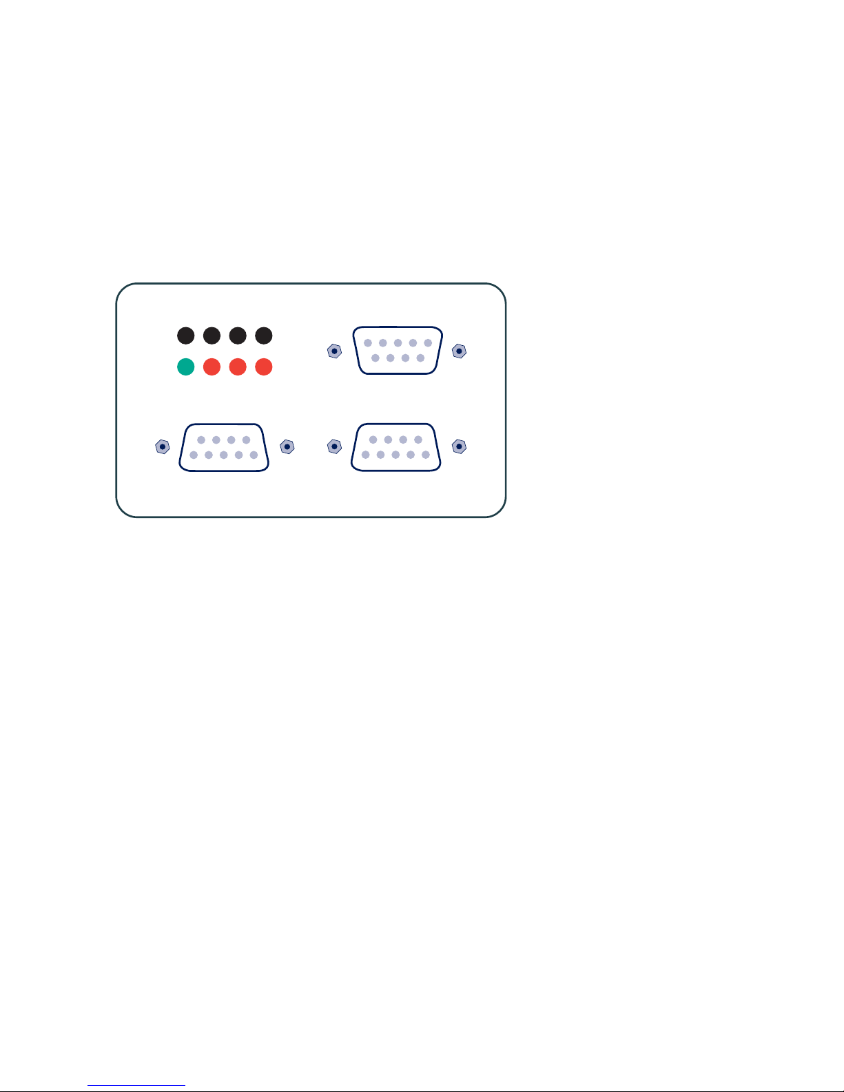
Mechanik und Gehäuse
Der Umschalter besitzt drei 9-polige serielle Schnittstellen und
ist in ein 45mm breites Kunststoffgehäuse zur Montage des Gerätes auf Normschienen nach DIN EN 50022-35
integriert.
Port A Port B
Port C
Power Error A B
Clear Dump
Zur Konfiguration der seriellen Schnittstellen und
1 der Umschalter-Betriebsarten muss das Gehäuse des
Gerätes geöffnet werden. Zu diesem Zweck empfiehlt es
sich, einen SUB-D-Stecker mit Gehäuse auf eine Schnittstelle
des Umschalters zu schrauben und den Gehäuse-Deckel mit
Hilfe des angeschraubten Steckers aus dem Gehäuse-Korpus
zu ziehen.
Anschlussbelegung RS232 (#85603)
Die RS232-Ports A und B sind als SUB-D-Buchse mit DCEBelegung, der Port C ist als SUB-D-Stecker mit DTE-Belegung
ausgeführt. Durch diese Anordnung ist gewährleistet, dass der
Umschalter in der Mehrzahl der Anwendungsfälle mit Standard
1:1-Kabeln in die Applikation eingeschleift werden kann. Zusätzlich erleichtert dieses Pinout die Inbetriebnahme der Installation, da der Datentransfer zunächst ohne Beteiligung des Umschalters durch einfaches Zusammenstecken der Kabel getestet werden kann.
8
W&T
RS232(/RS422/RS485) Multi Computer Adapter
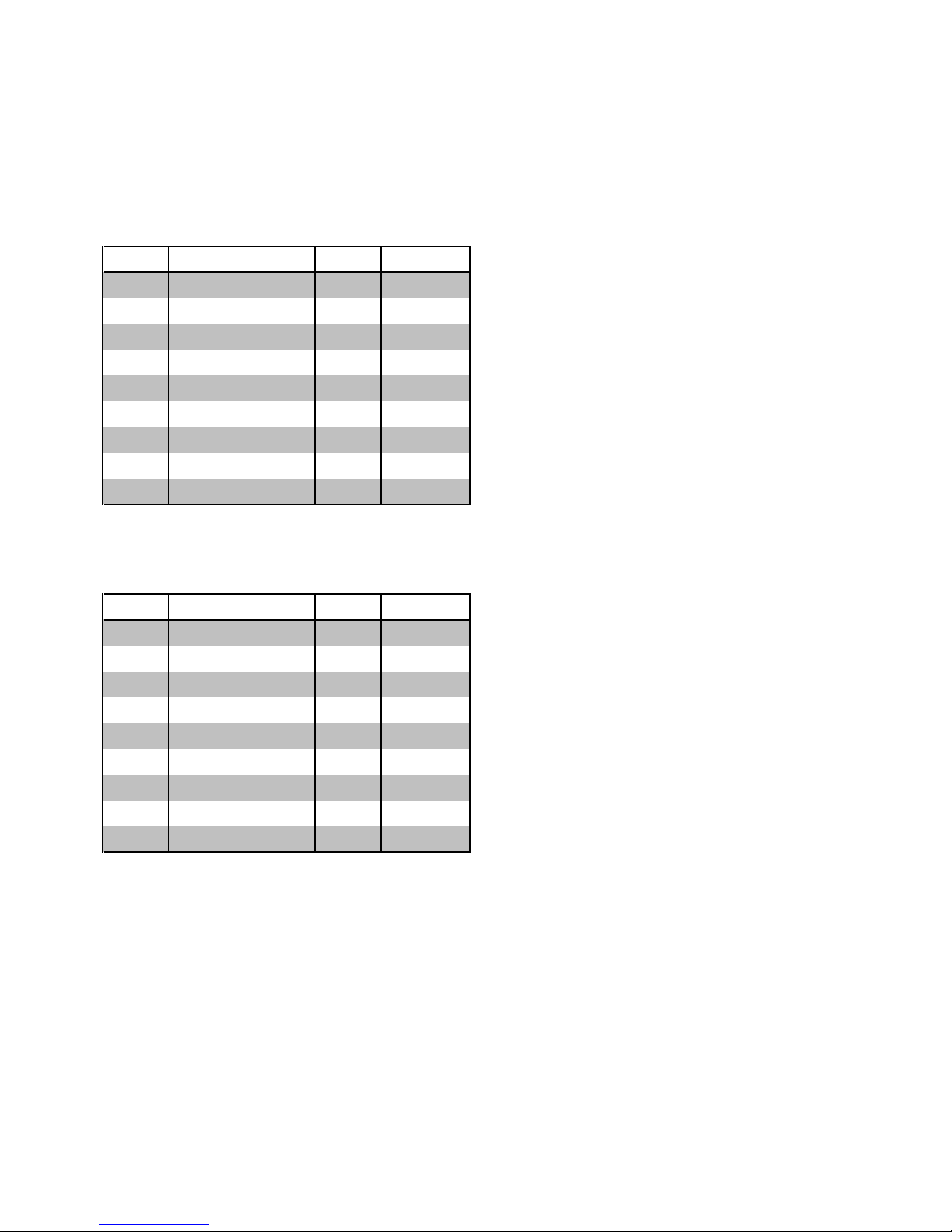
Das Pinout der einzelnen Schnittstellen können Sie den
folgenden Tabellen entnehmen.
RS232-Eingang Port A und B mit DCE-Belegung:
Pin# Funktion Signal Richtung
1 Freigabe-Pegel DCD Ausgang
2 Data out RxD Ausgang
3 Data In TxD Eingang
4 Handshake In DTR Eingang
5 Signalmasse GND GND
6 Handshake Out DSR Ausgang
7 unbelegt RTS Eingang
8 Handshake Out CTS Ausgang
9 Inaktiver Pegel RI Ausgang
RS232-Ausgang Port C mit DTE-Belegung:
Pin# Funktion Signal Richtung
1 unbelegt DCD Eingang
2 Data In RxD Eingang
3 Data Out TxD Ausgang
4 Handshake Out DTR Ausgang
5 Signalmasse GND GND
6 unbelegt DSR Eingang
7 Freigabepegel RTS Ausgang
8 Handshake In CTS Eingang
9 unbelegt RI Eingang
9
W&T
RS232(/RS422/RS485) Multi Computer Adapter
Irrtum und Änderung vorbehalten
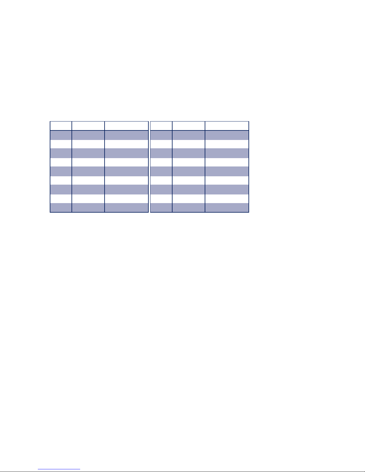
Anschlussbelegung RS232/RS422/RS485 (#85604)
Der RS232-/RS422-/RS485-Anschluss der Module ist als
9-poliger SUB-D-Stecker ausgeführt. Die Belegung der Steckverbinder können Sie den folgenden Tabellen entnehmen:
RS232-Schnittstelle RS422/RS485-Schnittstelle
Pin# Signal Funktion
1 DCD Eingang
2 RxD Eingang
3 TxD Ausgang
4 DTR Ausgang
5 GND Signal-Masse
6 DSR Eingang
7 RTS Ausgang
8 CTS Eingang
9 RI Eingang
Pin# Signal Funktion
1 TXD A Ausgang
2 RxD A Eingang
3 DTR A Ausgang
4 CTS A Eingang
5 GND Signal-Masse
6 TXD B Ausgang
7 RxD B Eingang
8 DTR B Ausgang
9 CTS B Eingang
Betriebsarten
Die Interface-Module sind über DIL-Schalter auf den einzelnen
Modulen auf verschiedene Betriebsarten einstellbar, die im Folgenden kurz beschrieben werden:
RS232
Das Schnittstellenmodul setzt alle verfügbaren TTL-Daten- und
Handshakesignale in RS232-Signale um. Es stehen in dieser
Betriebsart je ein Datenkanal (RxD und TxD) in jede Richtung,
sowie sechs Handshake-Kanäle (RTS, CTS, DSR, DCD, DTR und
RI) zur Verfügung.
RS422
Das Interface-Modul unterstützt je einen Daten- und einen
Handshake-Kanal (wahlweise DTR- oder RTS-HandshakeAusgang) in jede Richtung. Die RS422-Sender- und Empfängerbausteine sind immer aktiv.
RS485
In allen RS485-Betriebsarten steht jeweils ein Datenkanal in jede
Richtung zur Verfügung. Die Betriebsmodi unterscheiden sich

10
W&T
RS232(/RS422/RS485) Multi Computer Adapter
lediglich in der Art der Steuerung der RS485-Treiber- und
Empfängerbausteine.
RS485 4-Draht-Bus-Master
In dieser Betriebsart sendet der Master über ein Aderpaar
Requests an die Slaves, die auf einem weiteren, gemeinsamen
Aderpaar ihre Antworten an den Master senden. Die RS485Treiber und Empfänger sind in dieser Betriebsart, in der der
Master jederzeit senden kann und permanent auf die Slaves
hört, jederzeit aktiv.
RS485 4-Draht-Betrieb mit Handshake-Steuerung
Der RS485-Treiberbaustein wird mit einem TTL-Low-Pegel auf
der "DTR" oder "RTS"-Leitung eingeschaltet, während ein TTLHigh-Pegel auf dieser Leitung den Treiber in hochohmigen
Zustand bringt. Der Empfangskanal ist in dieser Betriebsart
immer aktiv.
RS485 2-Draht-Betrieb mit Handshake-Steuerung
Der RS485-Treiberbaustein wird mit einem TTL-Low-Pegel auf
der "DTR" oder "RTS"-Leitung eingeschaltet, während ein TTLHigh-Pegel auf dieser Leitung den Treiber in hochohmigen
Zustand bringt. Der Empfangskanal ist bei eingeschaltetem
Treiber deaktiviert, bei hochohmigem Treiber dagegen eingeschaltet.
RS485 4-Draht-Betrieb mit automatischer Steuerung
Der RS485-Treiberbaustein wird mit jeder Datenausgabe automatisch aktiviert und nach Ende der Datenausgabe wieder in
den hochohmigen Zustand gebracht. Der Empfangskanal ist in
dieser Betriebsart immer aktiv.
RS485 2-Draht-Betrieb mit automatischer Steuerung
Der RS485-Treiberbaustein wird mit jeder Datenausgabe automatisch aktiviert und nach Ende der Datenausgabe wieder in
den hochohmigen Zustand gebracht. Der Empfangskanal ist bei
eingeschaltetem Treiber deaktiviert, bei hochohmigem Treiber
dagegen eingeschaltet.
11
W&T
RS232(/RS422/RS485) Multi Computer Adapter
Irrtum und Änderung vorbehalten
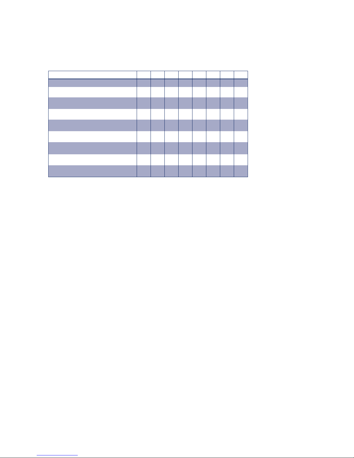
Die Bedeutung des Betriebsart-DIL-Schalters entnehmen Sie
bitte der folgenden Tabelle:
Betriebsart SW1 SW2 SW3 SW4 SW5 SW6 SW7 SW8
RS232 OFF OFF OFF OFF OFF OFF OFF ON
RS422, RS485, 4-Draht Bus-Master,
DTR-Handshake
OFF OFF OFF ON OFF
**
OFF
RS422, RS485, 4-Draht Bus-Master,
RTS-Handshake
OFF OFF OFF OFF ON
**
OFF
RS485, 4-Draht / 2-Draht mit Echo
DTR-Steuerung
OFF OFF ON ON OFF
**
OFF
RS485, 2-Draht ohne Echo
DTR-Steuerung
ON OFF ON ON OFF
**
OFF
RS485, 4-Draht / 2-Draht mit Echo
RTS-Steuerung
OFF OFF ON OFF ON
**
OFF
RS485, 2-Draht ohne Echo
RTS-Steuerung
ON OFF ON OFF ON
**
OFF
RS485, 4-Draht / 2-Draht mit Echo
Automatik-Steuerung
OFF ON OFF ON OFF
**
OFF
RS485, 2-Draht ohne Echo
Automatik-Steuerung
ON ON OFF ON OFF
**
OFF
*) Terminierung des Bussystems, falls erforderlich.
Die Terminierungs-DIL-Schalter SW6 und SW7 dürfen bei RS232Betrieb des Moduls unter keinen Umständen eingeschaltet
werden. Dies bewirkt eine stark erhöhte Stromaufnahme des
Moduls und kann zum Ausfall des RS232-Treibers führen.
Terminierung
Alle RS485-Betriebsarten erfordern zwingend den Abschluss
des Bussystems mit einem Terminierungsnetzwerk. Diese auf
dem Modul integrierte Widerstands-Kombination erfüllt in
RS485-Applikationen zwei Aufgaben:
1. Die angeschlossene Leitung wird in der Größenordnung
ihres Wellenwiderstandes abgeschlossen, wodurch Signalreflektionen an den Enden des Kabels verhindert werden.
2. In den hochohmigen Phasen des Busbetriebs wird ein
definierten Ruhezustand sicherstellt.
Die Verbindung des Bussystems mit dem Terminierungsnetzwerk darf ausschließlich im RS485- und RS422-Betrieb, jedoch nicht im RS232-Betrieb vorgenommen werden.

12
W&T
RS232(/RS422/RS485) Multi Computer Adapter
Durch Schließen der DIL-Schalter 6 und 7 auf dem Schnittstellen-Modul werden die Busanschlüsse mit dem
Widerstandsnetzwerk verbunden.
Anzeige- und Bedien-Elemente
Der Umschalter verfügt über vier Leuchtdioden, von denen die
grüne „Power“-LED die korrekte Spannungsversorgung und die
mit „A“ und „B“ gekennzeichneten LEDs den jeweils
aktiven Eingangskanal signalisieren. Die mit „Error“ gekennzeichnete LED zeigt das Auftreten von Paritäts- oder Rahmenfehlern im laufenden Datenverkehr an und kann lediglich
explizit durch Drücken der „Clear“-Taste gelöscht werden.
Mit Hilfe der „Clear“-Taste wird der Umschalter in seinen Grundzustand zurückgesetzt und alle internen Daten- und Fehlerspeicher gelöscht.
Bei Betätigung der „Dump“-Taste im Einschaltmoment des
Gerätes wird am per DIL-Schalter ausgewählten seriellen Port die
aktuelle Einstellung des Umschalters ausgegeben. Weitere Informationen zu dieser Funktion finden Sie im Kapitel
Diagnosefunktionen > Einstellungs-Dump.
Konfiguration der seriellen Schnittstellen
Alle drei Ports des Umschalters sind hinsichtlich Übertragungsrate, Datenformat und Handshakeverfahren völlig
unabhängig voneinander konfigurierbar. Durch diese
Eigenschaft lassen sich auch Endgeräte verbinden, die unterschiedliche seriellen Datenformate verwenden.
Der modulare Aufbau des Umschalters ermöglicht durch den
Einbau anderer Schnittstellenmodule zusätzlich eine Konvertierung des Schnittstellentyps innerhalb des Gerätes.
Speziell bei größeren Stückzahlen ist die Umrüstung des
Umschalters mit anderen Schnittstellenmodulen eine
wirtschaftliche Alternative zu den sonst erforderlichen
13
W&T
RS232(/RS422/RS485) Multi Computer Adapter
Irrtum und Änderung vorbehalten
externen Konvertern. Fragen Sie Sonderversionen des Umschalters bei Bedarf bitte bei uns an.
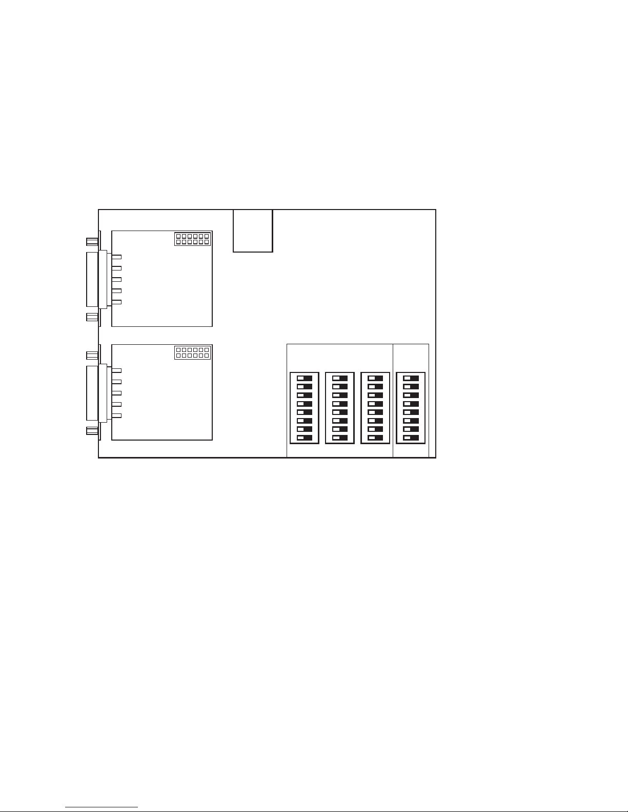
Die Einstellung der seriellen Parameter geschieht über drei DILSchalterbänke SW1..SW3 im Inneren des Gerätes. Die
Position und Zuordnung der DIL-Schalterbänke zum
jeweiligen Port können Sie der folgenden Skizze entnehmen:
SW1 SW2 SW3 SW4
Serielle Parameter
Port A Port B Port C
Modus
Port B
Port A
Serielles Format
Baudrate, Anzahl der Datenbit und ein eventuell verwendetes
Paritätsbit können getrennt für jede Schnittstelle des
Umschalters konfiguriert und damit dem Format des
angeschlossenen Endgerätes angepasst werden.
Handshake-Verfahren
Alle seriellen Schnittstellen des Umschalters können
unabhängig voneinander wahlweise auf Hardware-Handshake
oder auf XON-/XOFF-Handshake eingestellt werden. Ein
Betrieb des Umschalters ohne Handshake wird nicht empfohlen.

14
W&T
RS232(/RS422/RS485) Multi Computer Adapter
Wenn einer der internen Buffer des Umschalters fast vollständig mit Daten gefüllt ist, so wird an der entsprechenden
Schnittstelle ein XOFF-Code (13H) ausgegeben bzw. beim
nächsten empfangenen Zeichen der Hardware-Handshake
Ausgang auf 'Sperren' (negativer Pegel) gesetzt. Hat sich der
Buffer wieder etwas geleert, so wird ein XON-Code (11H)
ausgegeben bzw. der Hardware-Handshake-Ausgang auf 'Freigabe' (positiver Pegel) gesetzt.
Empfängt der Umschalter einen XOFF-Code oder erkennt er auf
dem Hardware-Handshake-Eingang einen Sperr-Pegel
(negativer Pegel), so stoppt er die Datensendung auf der
entsprechenden Schnittstelle spätestens ein Byte nach
Erkennen dieses Zustandes. Empfängt der Umschalter einen
XON-Code oder erkennt er am Hardware-Handshake-Eingang einen Freigabe-Pegel (positiver Pegel), so setzt er die
Datensendung fort.
Die XON- und XOFF-Codes dienen ausschließlich dem
Handshake, diese Codes sind also keine Daten und dürfen auch
nicht in den Nutzdaten enthalten sein. Wird allerdings Hardware-Handshake verwendet und der Umschalter entsprechend
konfiguriert, so werden die XON- und XOFF-Codes als normale
Daten behandelt.
Bei offenen oder falsch beschalteten Hardware-HandshakeEingängen sendet der Umschalter also ggf. keine Daten auf der
betreffenden Schnittstelle. Falls Sie nur SoftwareHandshake verwenden und den Umschalter entsprechend konfigurieren, tritt dieses Problem natürlich nicht auf.
Einstellung der DIL-Schalter
Die DIL-Schalterbänke SW1, SW2 und SW3 haben für alle drei
Schnittstellen einen identische Funktionsumfang: Die
einzelnen Schalter bestimmen die Übertragungsgeschwindigkeit, die Anzahl der Datenbit, die verwendete Parität und das Handshake-Verfahren der jeweiligen Schnittstelle.
DieFunktion der einzelnen Schalter ist in der folgenden Tabelle
erläutert:

15
W&T
RS232(/RS422/RS485) Multi Computer Adapter
Irrtum und Änderung vorbehalten
Handshake
S1
Datenbits
S6
Hardware-Handshake
off
7 Datenbit
off
Software-Handshake
ON
8 Datenbit
ON
Parität
S7 S8
Keine Parität
X off
Ungerade Parität
off ON
Gerade Parität
ON ON
Baudrate S2 S3 S4 S5
150 Baud off off off off
300 Baud ON off off off
600 Baud off ON off off
1200 Baud ON ON off off
2400 Baud off off ON off
4800 Baud ON off ON off
9600 Baud off ON ON off
19200 Baud ON ON ON off
38400 Baud off off off ON
57600 Baud ON off off ON
64000 Baud off ON off ON
76800 Baud ON ON off ON
115200 Baud off off ON ON
Betriebsarten
Der RS232 Multi Computer Adapter 85603 verfügt über vier
Betriebsmodi, die im folgenden beschrieben werden.
In allen Betriebsarten zeigen die LEDs „A“ und „B“ an der Front
des Umschalters an, welcher verfügbare Datenpfad gerade aktiviert ist.
Manueller Modus
Die einfachste aller Betriebsarten erlaubt die manuelle
Umschaltung der bidirektionalen Verbindung zwischen Port A
und Port C bzw. zwischen Port B und Port C.

16
W&T
RS232(/RS422/RS485) Multi Computer Adapter
Durch Betätigung der Taste unterhalb der LED A wird der
Signalweg Port A <> Port C durchgeschaltet, während die Taste
unterhalb der LED B den Pfad Port B <> Port C
aktiviert. Nach einem Reset des Umschalters ist grundsätzlich
der Kanal Port A <> Port C aktiv. LED A und B zeigen den jeweils
durchgeschalteten Kanal an.
Der Umschalter sperrt über ein Handshake-Stopsignal oder ein
XOFF-Zeichen automatisch den Datenfluss auf dem nicht aktiven Kanal.
Standardmodus
In dieser Betriebsart erfolgt die automatische Umschaltung
zwischen beiden Datenquellen in einem zeitgesteuerten
Betrieb: Der Datensender, der zuerst etwas ausgeben
möchte, sperrt über ein vom Umschalter erzeugtes HandshakeStopsignal oder ein XOFF-Zeichen automatisch die
Ausgabe der anderen Quelle.
Legt der erste Datensender eine Pause ein, so ist nach einer einstellbaren Umschalt-Zeit auch der zweite Eingang wieder
empfangsbereit.
Der Multi Computer Adapter regelt in dieser Betriebsart den
Datenfluß automatisch über das an der jeweiligen Schnittstelle
eingestellte Handshake-Verfahren.

17
W&T
RS232(/RS422/RS485) Multi Computer Adapter
Irrtum und Änderung vorbehalten
Transparentmodus
Der Datensender, der zuerst etwas ausgeben möchte, wird
sofort mit dem seriellen Endgerät verbunden. Alle am
anderen Eingang des Umschalters empfangenen Daten
werden verworfen, solange das Endgerät mit dem ersten
Datensender verbunden ist. Zur Freischaltung des zweiten Eingangs müssen zwei Bedingungen erfüllt sein:
. Die erste Datenquelle hat seit einer einstellbaren Umschalt-
zeit keine Daten mehr gesendet.
. Am zweiten Eingang wurden seit einer ebenfalls konfigurier-
baren Timeout-Zeit keine Daten empfangen.
Dieser Mechanismus verhindert, dass der Eingang mitten in
einem Protokollblock aktiviert wird und somit ein bruchstückhafter Datensatz den Empfänger erreicht.
In dieser Betriebsart unterstützt der Multi Computer Adapter
ausschließlich die beiden Datenleitungen RxD und TxD. Der
Umschalter greift in dieser Betriebsart nicht in den Datenfluss
ein, sondern reicht die empfangenen Zeichen transparent vom
Sender zum jeweiligen Empfänger durch. Eine eventuell erforderliche Steuerung des Datenflusses müssen die Endgeräte mit
einem geeigneten Protokoll selbst sicherstellen.
Splittermodus
In dieser Betriebsart werden alle an Port C eingehenden Daten
an die Ports A und B weitergeleitet (C r A und C r B).
An A und B eingehende Daten werden an C weitergeleitet. In
diese Richtung kann allerdings immer nur eine
Kommunikationsstrecke aktiv sein (A r C oder B r C). Voraussetzung für das Zustandekommen eines solchen Rückkanals
ist, dass seit der eingestellten Umschaltzeit am konkurrierenden Port (B oder A) keine Daten eingegangen sind.
Ist ein Rückkanal durchgeschaltet (A r C oder B r C), werden
alle am konkurrierenden Port (B oder A) empfangenen Daten

18
W&T
RS232(/RS422/RS485) Multi Computer Adapter
verworfen. Auch bei aktivem Rückkanal werden an C empfangene Daten an A und B weitergeleitet. Der Abbau der Verbindung
erfolgt, wenn für die eingestellte Umschaltzeit keine Daten am
aktiven Port empfangen wurden.
Die LEDs „A“ und „B“ auf der Front des Gerätes zeigen einen aktiven Kommunikationsweg an.
Diese Betriebsart unterstützt weder Hard- noch Soft-
1 warehandshake.
Einstellung der Betriebsarten
Die Betriebsarten des Umschalters werden mit DIL-Schalterbank
SW4 ausgewählt und parametriert.
Die Funktion der einzelnen DIL-Schalter der Schalterbank SW4
entnehmen Sie bitte der folgenden Tabelle.
Betriebsart S1 S2 Dump-Ausgabe S3 S4
Manueller Modus off off Port A off off
Standardmodus ON off Port B ON off
Transparentmodus off ON Port C off ON
Splittermodus ON ON alle Ports ON ON
Umschaltzeit S5 S6 Timeout-Zeit S7 S8
5 Sekunden off off 0 Millisekunden off off
15 Sekunden ON off 30 Millisekunden ON off
30 Sekunden off ON 90 Millisekunden off ON
120 Sekunden ON ON 500 Millisekunden ON ON
Diagnosefunktionen
Die Inbetriebnahme einer RS232-Schnittstelle bereitet häufig
Schwierigkeiten, da sowohl Pin-Belegung als auch die Übertragungsparameter stimmen müssen, um eine fehlerfreie

19
W&T
RS232(/RS422/RS485) Multi Computer Adapter
Irrtum und Änderung vorbehalten
Datenübertragung zu ermöglichen. Zur Überpüfung der
Konfiguration hat der RS232 Multi Computer Adapter 85603 mit
dem Einstellungs-Dump eine Funktion integriert, die bei der Installation sehr hilfreich sein kann.
Einstellungs-Dump
Als erster Test im Zuge der Inbetriebnahme kann der im Umschalter integrierte Einstellungs-Dump dienen, bei dem der Umschalter selbständig einen Text generiert, der alle programmierten Einstellungen des 85603 wiedergibt.
Der Einstellungs-Dump hat mehrere Funktionen:
. Testen von Datenleitungen und Signalmasse
. Testen der Übertragungs-Parameter
. Übersichtliche Ausgabe aller Einstellungen
. Handshake-Test für Datenausgang aus dem 85603
Um auch bei fehlerhaften Handshake-Bedingungen den Einstellungs-Dump erzeugen zu können, wird bei gesperrter Schnittstelle der Dump ebenfalls ausgegeben, jedoch mit
einer sehr niedrigen Geschwindigkeit. Es gilt also:
. Handshake freigegeben r schnelle Ausgabe des Dump
. Handshake gesperrt r langsame Ausgabe des Dump
Halten Sie den „Dump“-Taster gedrückt und verbinden Sie anschließend den Umschalter mit seiner Spannungsversorgung.
Nach Loslassen des Tasters wird auf dem mit den DIL-Schaltern
SW4.3 und SW4.4 eingestellten Port die folgende Ausgabe generiert:

20
W&T
RS232(/RS422/RS485) Multi Computer Adapter
PU 40,6000;;SI 0.2,0.3;DT
LB
LB RS232 MULTI COMPUTER ADAPTER, 0MBYTE
LB VERSION 1.4
L B TRANSPARENT MODE (TIMEOUT MODE)
LB
LB PORT A: BAUD 9600
LB DATA 8
LB PARITY NO
LB
LB HANDSHAKE HARD
LB
LB PORT B: BAUD 9600
LB DATA 8
LB PARITY NO
LB
LB HANDSHAKE HARD
LB
LB PORT C: BAUD 9600
LB DATA 8
LB PARITY NO
LB
LB HANDSHAKE HARD
LB

21
W&T
RS232(/RS422/RS485) Multi Computer Adapter
Irrtum und Änderung vorbehalten
Anschluss-Beispiel
Verbindung 2 PC <> 1 Peripheriegerät mit HardwareHandshake
1:1 - Kabel
1:1 - Kabel
PC 2
COM-Port
RS232
PC 1
COM-Port
RS232
Port A
(DB9-Buchse)
Port B
(DB9-Buchse)
RS232 Multi
Computer Adapter, #85603
Port C
(DB9-Stecker)
Peripheriegerät
mit
DTE-Belegung
23458
2(3) 3(2) 5(8) 7(5) 20(4)
Data In
Data Out
Hands. Out
Hands. In
Signal GND
TxD
RxD
CTS
GND
DTR
DB25 (DB9)

22
W&T
RS232(/RS422/RS485) Multi Computer Adapter
Technische Daten
Serielle Schnittstellen: #85603: 3 x RS232 (Port A u. B:
Buchse, Port C: Stecker)
#85604: 3 x RS232/422/485 (Port
A, B u. C: Stecker)
alle Ports unabhängig voneinander
konfigurierbar
Baudrate: 150 .. 115.200 Baud
Datenformat: 7, 8 Datenbit, No, Even, Odd Parity
Unterstützte Signale: RxD, TxD, CTS, DTR
Handshake: wahlweise Hardware- oder
XON-/XOFF-Handshake
Betriebsarten: Standard- & Transparentmodus
Umschaltzeiten: Einstellbar in Schritten von
5, 15, 30, 120 Sekunden
(geänderte Werte auf Anfrage)
Stromversorgung: Steckernetzteil oder potential-
freie 12-24V AC/DC
Leerlauf-Stromaufnahme: typ. 25 mA @24V DC
ESD-Festigkeit: bis 15kV nach IEC 801-2,Stufe 4
Umgebungstemperatur: Lagerung: -40..+70°C
Betrieb: 0..+60°C bei
externer 24V-Versorgung
Gehäuse / Abmessungen: Kunststoff-Gehäuse für Norm-
schienen-Montage nach DIN
EN 50022-35, 105 x 75 x 45mm
Gewicht: ca. 500g inkl. Netzteil

W&T
Manual
RS232 Multi Computer Adapter
RS232/RS422/RS485 Multi Computer Adapter
Typ RS232(/RS422/RS485)
Multi Computer Adapter
Modell 85603/ 85604
Release 1.5

W&T
© 04/2009, Wiesemann & Theis GmbH
Subject to error and alteration:
Since it is possible that we make mistakes, you mustn’t use any
of our statements without verification. Please, inform us of any
error or misunderstanding you come about, so we can identify
and eliminate it as soon as possible.
Carry out your work on or with W&T products only to the
extent that they are described here and after you have completely read and understood the manual or guide. We are not liable
for unauthorized repairs or tampering. When in doubt, check
first with us or with your dealer.

W&T
The W&T Multi Computer Adapter model permits automatically
controlled, bi-directional connection of two data sources to one
peripheral device.
With this unit two PCs, a serial printer, a plotter, a portable
scanner or a card reader for example can be shared without requiring manual intervention to switch them: automatic selection is on the first come, first served principle.
The interfaces of the Multi Computer Adapter can be
configured independently of each other, so that converting the
baud rate, data format and handshake procedure is no problem.
Additional information about W&T products and new developments can be found on the Internet at
http://www.wut.de or are
available in the e-mail infograms offered by the W&T Interface
Club, which you can sign up for at the W&T homepage.

W&T
Contents
Overview ..............................................................................6
Supply voltage ..................................................................... 6
Mechanical features and enclosure ........................................ 7
Wiring assignments RS232 (#85603) ..................................... 7
Wiring assignments RS232/RS422/RS485 (#85604) ................ 9
Display and control elements .............................................. 12
Configuring the serial ports ................................................. 12
Serial format ....................................................................... 13
Handshake procedure ......................................................... 13
Setting the format - DIL switches .......................................... 14
Modes ............................................................................... 15
Manual mode ..................................................................... 15
Standard mode ................................................................... 16
Transparent mode .............................................................. 16
Splitter mode ...................................................................... 17
Setting the modes .............................................................. 17
Diagnostic functions .......................................................... 18
Settings dump .................................................................... 18
Connection example ........................................................... 20
Technical Data ................................................................... 21

W&T

6
W&T
Overview
The W&T Multi Computer Adapter permits a
bi-directional connection of two serial data sources to a
peripheral device. Automatic switching between the two
senders is done on a time-controlled basis: The data sender
that wants first to output something automatically blocks the
outputs from the other source. If the data sender implements a
pause, both inputs are again ready to receive after a
configurable timeout time. Two LEDs on the front panel of the
switch indicate which of the two input channels is
currently active.
Supply voltage
The supply voltage for the RS232 Multi Computer Adapter is
provided by an integrated switched-mode power supply. This
features a variable input voltage range and allows the T-switch
to be powered using the AC adapter provided or alternately by
any AC or DC voltage between 12 and 24V. The supply connection is reverse polarity protected and is made using the
included plug-in screw terminal.
When powering the Multi Computer Adapter e x -
1 ternally you must ensure that the supply voltage used
is potential-free. Voltage sources with a ground reference
can damage the device and/or the connected serial devices.
We therefore recommend using the power supply included
in the scope of delivery.

7
W&T
RS232(/RS422/RS485) Multi Computer Adapter
Subject to error and alteration
Mechanical features and enclosure
The Multi Computer Adapter comes with three 9-pin serial ports
and is integrated into a 45mm wide plastic housing for
mounting on standard rails conformal with DIN EN 50022-35.
Port A Port B
Port C
Power Error A B
Clear Dump
Configuring the serial ports and device operating
1 modes requires opening the housing of the device.
For this purpose it is advantageous to screw a SUB-D plug
with body to one port on the Multi Computer Adapter and
use the attached plug to assist in pulling off the housing
cover.
Wiring assignments RS232 (#85603)
The RS232 ports A and B are implemented as SUB-D female
connectors with DCE pin functions, and port C as a SUB-D male
connector with DTE pin functions. This design ensures that the
device can be wired into the majority of applications with standard 1:1 cables. In addition, this pin configuration make installation and startup easier, since the data transfer can be tested
first without involving the T-switch by simply connecting the
cables together.

8
W&T
RS232(/RS422/RS485) Multi Computer Adapter
The pinout for the individual ports can be found in the following tables.
RS232 input Port A and B with DCE pin functions:
Pin# Function Signal Direction
1 always "on" DCD output
2 data out RxD output
3 data in TxD input
4 handshake in DTR input
5 signal GND GND GND
6 handshake out DSR output
7 not connected RTS input
8 handshake out CTS output
9 always "off" RI output
RS232 output Port C with DTE pin functions:
Pin# Function Signal Direction
1 not connected DCD input
2 data in RxD input
3 data out TxD output
4 handshake out DTR output
5 signal GND GND GND
6 not connected DSR input
7 always "on" RTS output
8 handshake in CTS input
9 not connected RI input

9
W&T
RS232(/RS422/RS485) Multi Computer Adapter
Subject to error and alteration
Wiring assignments RS232/RS422/RS485 (#85604)
The RS232/RS422/RS485 connection for the modules is
configured as a 9-pin male SUB-D connector. Refer to the following tables for connector pin assignments:
RS232 interface RS422/RS485 interface
pin# signal function
1 TXD A output
2 RxD A input
3 DTR A output
4 CTS A input
5 GND GND
6 TXD B output
7 RxD B input
8 DTR B output
9 CTS B input
pin# signal function
1 DCD input
2 RxD input
3 TxD output
4 DTR output
5 GND GND
6 DSR input
7 RTS output
8 CTS input
9 RI input
Operating modes
The Interface Modules are configurable for the following
modes using DIL switches, which are mounted on the modules:
RS232
The Interface Module converts all available TTL data and handshake signals into RS232 signals. This mode provides one RxD
and TxD channel each in the respective direction, along with
six handshake channels (RTS, CTS, DSR, DCD, DTR and RI).
RS422
The Interface Module supports one data and one handshake
channel each (selectable DTR or RTS handshake output). The
RS422 sender/receivers are always active.
RS485
One data channel in each direction is always available in all
RS485 modes. These modes differ only in how the RS485
transceivers are controlled.
RS485 4-wire bus master
In this mode the master uses a conductor pair to send
requests to the slaves, which in turn send their replies to the

10
W&T
RS232(/RS422/RS485) Multi Computer Adapter
master on an additional common conductor pair. The RS485
transceivers are always active in this mode, whereby the master
can always send and is constantly listening for the slaves.
RS485 4-wire mode with handshake control
The RS485 driver chip is turned on with a TTL Low level on the
„DTR“ or „RTS“ line, whereas a TTL High level on this line puts
the driver in a high-impedance state. The receiving channel in
this mode is always active.
RS485 2-wire mode with handshake control
The RS485 driver chip is turned on with a TTL Low level on the
„DTR“ or „RTS“ line, whereas a TTL High level on this line puts
the driver in a high-impedance state. The receiving channel is
deactivated when the driver is on, and enabled when the driver
is in the high-impedance state.
RS485 4-wire mode with automatic control
The RS485 driver chip is automatically activated whenever data
are output and brought to the high-impedance state when data
output is finished. The receiving channel in this mode is always
active.
RS485 2-wire mode with automatic control
The RS485 driver chip is automatically activated when data are
output and brought to the high-impedance state when data
output is finished. The receiving channel is deactivated when
the driver is turned on, and enabled when the driver is in the
high-impedance state.

11
W&T
RS232(/RS422/RS485) Multi Computer Adapter
Subject to error and alteration
The DIL switch settings can be found in the following table:
Operating mode SW1 SW2 SW3 SW4 SW5 SW6 SW7 SW8
RS232 OFF OFF OFF OFF OFF OFF OFF ON
RS422, RS485, 4-wire bus master
DTR handshake
OFF OFF OFF ON OFF
**
OFF
RS422, RS485, 4-wire bus master
RTS handshake
OFF OFF OFF OFF ON
**
OFF
RS485, 4-wire / 2-wire with echo
DTR control
OFF OFF ON ON OFF
**
OFF
RS485, 2-wire without echo
DTR control
ON OFF ON ON OFF
**
OFF
RS485, 4-wire / 2-wire with echo
RTS control
OFF OFF ON OFF ON
**
OFF
RS485, 2-Draht without echo
RTS control
ON OFF ON OFF ON
**
OFF
RS485, 4-wire / 2-wire with echo
automatic control
OFF ON OFF ON OFF
**
OFF
RS485, 2-wire without echo
automatic control
ON ON OFF ON OFF
**
OFF
*) Terminating the bus system when required.
The terminating DIL switches SW6 and SW7 must never be in
the ON position when using the module in RS232 mode. This
will result in a significant increase in the current draw and may
cause the RS232 driver to fail.
Termination
All RS485 modes require termination of the bus system with a
termination network. The resistor combination integrated in the
module performs two tasks in RS485 applications:
1. The connected line is terminated corresponding to its
impedance, which prevents signal reflections at the cable end.
2. In the high-impedance phases of bus operation a defined
quiescent state is ensured.
The bus system is allowed to be terminated with the termination network only in RS485 and RS422 modes, but not in RS232
mode.
Closing DIL switches 6 and 7 on the Interface Module
connects the bus terminals to the resistance
network.

12
W&T
RS232(/RS422/RS485) Multi Computer Adapter
Display and control elements
The device uses four LEDs, a green „Power“ for indicating
correct supply voltage and the LEDs marked „A“ and „B“ to indicate which input channel is active.
The LED marked „Error“ indicates the presence of parity or
framing errors in running data traffic and can only be
cleared explicitly by pressing the „Clear“ key. The „Clear“ key
resets the T-switch and deletes all internal data and error
memories.
Pressing the „Dump“ key when the device is turned on
outputs the current setting of the T-switch on whichever
serial port has been selected using the DIL switches.
Additional information about this function can be found in the
section Diagnostic functions > Setting-dump.
Configuring the serial ports
All three ports on the T-switch can be configured for
transmission rate, data format and handshake procedure completely independently of each other. This feature allows you to
connect the T-switch to terminal devices which use different
serial data formats.
The modular construction of the T-switch allows you to
incorporate other interface modules to convert the interface
type within the device. Especially when larger quantities are
involved changing over the T-switch with other interface
modules represents an economical alternative to the
external converters otherwise commonly used. Please contact
us with any requirements for special versions of the T-switch.
You set the serial parameters using three DIL switch banks
SW1..SW3 inside the device. The position and arrangement of
the DIL switch banks with respect to the corresponding port can
be seen in the following sketch.

13
W&T
RS232(/RS422/RS485) Multi Computer Adapter
Subject to error and alteration
SW1 SW2 SW3 SW4
Serial Port Settings
Port A Port B Port C
Operat.
Mode
Port B
Port A
Serial format
Baud rate, number of data bits and any parity bit which may be
used can be configured separately for each port on the
T-switch, so that the format can be adapted to any connected
terminal device.
Handshake procedure
All serial ports on the T-switch can be set to hardware
handshake or XON/XOFF handshake independently of each
other. Operating the T-switch with no handshake is not
recommended.
When one of the internal buffers in the T-switch is nearly filled
with data, an XOFF code (13H) is output on the corresponding
port and for the next received character the hardware handshake output is set to ‚Block‘ (negative level). Once the buffer
has been emptied again, an XON code (11H) is output and the
hardware handshake output is set to ‚Enable‘ (positive level).

14
W&T
RS232(/RS422/RS485) Multi Computer Adapter
If the T-switch receives an XOFF code or detects a block level
(negative level) on the hardware handshake input, it stops
sending data on the corresponding port no later than one byte
after this state is detected. If the T-switch receives an XON code
or detects an enable level (positive level) on the hardware
handshake input, it resumes sending data.
The XON and XOFF codes are used only for the handshake;
these codes are not data and are also not allowed to be
contained in the user data. If a hardware handshake is used
however and the T-switch is correspondingly configured, the
XON and XOFF codes are treated as normal data.
When hardware handshake inputs are open or improperly wired,
the T-switch may send no data on the affected port.
If you use only software handshake and configure the
T-switch accordingly, this problem will of course not occur.
Setting the format - DIL switches
The DIL switch banks SW1, SW2 and SW3 have the same
scope of functions for all three ports: the individual switches
determine the transmission speed, the number of data bits, the
parity and the handshake procedure of the respective port. The
function of the individual switches can be seen in the following
tables:
handshake
S1
data bit
S6
hardware handshake
off
7 data bit
off
software handshake
ON
8 data bit
ON
parity
S7 S8
no parity
X off
odd parity
off ON
even parity
ON ON

15
W&T
RS232(/RS422/RS485) Multi Computer Adapter
Subject to error and alteration
baudrate S2 S3 S4 S5
150 Baud off off off off
300 Baud ON off off off
600 Baud off ON off off
1200 Baud ON ON off off
2400 Baud off off ON off
4800 Baud ON off ON off
9600 Baud off ON ON off
19200 Baud ON ON ON off
38400 Baud off off off ON
57600 Baud ON off off ON
64000 Baud off ON off ON
76800 Baud ON ON off ON
115200 Baud off off ON ON
Modes
The RS232 Multi Computer Adapter model 85603 offers
four operating modes, which are described in the following.
In all operating modes the LEDs „A“ and „B“ on the front panel
of the Multi Computer Adapter are used to indicate which data
path is currently active.
Manual mode
The simplest of all operating modes enables manual toggling
of the bi-directional connection between Port A and Port C or
between Port B and Port C.
Pressing the key below LED A opens path Port A <> Port C,
whereas pressing the key below LED B activates the path
Port B <> Port C. After the selector switch is reset the Port A <>
Port C channel is always active. LEDs A and B indicate which
channel is active.
The selector switch uses a handshake signal ir an XIFF
character to automatically block data flow on the non-active
channel.

16
W&T
RS232(/RS422/RS485) Multi Computer Adapter
Standard mode
In this mode switching between both data sources is
automatic on a time basis: the data sender that wants to send
something first uses a handshake stop signal or XOFF character generated by the T-switch to automatically block sending
from the other source.
If the first data sender inserts a pause, then the second input is
again ready to receive after a settable switching time. The multi-computer adapter automatically controls the data flow in this
mode using the handshake procedure set on the respective
port.
Transparent mode
The data sender that wants to send something first is
immediately connected to the serial terminal device. All data received on the other input of the T-switch are rejected as long
as the terminal device is connected to the first data
sender. Two conditions must be met in order to enable the second input:
. The first data source has sent no more data since a
settable switching time.
. No more data have been received on the second input
since a likewise configurable timeout time.
This mechanism prevents the input from being activated in the
middle of a protocol block and thereby a fragmented data
record from reaching the receiver.
In this mode the Multi Computer Adapter supports only the two
data lines RxD and TxD. The T-switch does not interfere in the
data flow in this mode, but rather transparently
passes the received data from the sender to the respective receiver. The terminal devices themselves must provide for any
required control of the data flow.

17
W&T
RS232(/RS422/RS485) Multi Computer Adapter
Subject to error and alteration
Splitter mode
In this mode all data arriving at Port C are passed to Ports A
and B (C r A und C r B).
Data arriving at A and B are passed to C. Only one
communications line may however be active in this direction (A
r C oder B r C). The prerequisite for establishing such
feedback channel is that no data have arrived at the competing
port (B or A) since the set reverse time.
If feedback channel is open (A r C oder B r C), all data received
at the competing port (B or A) are rejected. Even is a feedback
channel active, data received at C are passed to A and B. The
connection is closed if no date are received at the active port
during the set reverse time.
LEDs „A“ and „B“ on the front panel indicate an active
communications path.
This mode supports neither hard- nor software hand-
1 shake.
Setting the modes
The modes of the device are selected and configured using the
DIL switch bank SW4.
The function of the individual DIL switches in switch bank SW4
is shown in the following table.

18
W&T
RS232(/RS422/RS485) Multi Computer Adapter
Operating mode S1 S2 Dump-Output S3 S4
Manual mode off off Port A off off
Standard mode ON off Port B ON off
Transparent mode off ON Port C off ON
Splitter mode ON ON all ports ON ON
Switching time S5 S6 Timeout S7 S8
5 seconds off off 0 milliseconds off off
15 seconds ON off 30 milliseconds ON off
30 seconds off ON 90 milliseconds off ON
120 seconds ON ON 500 milliseconds ON ON
Diagnostic functions
Starting up an RS232 port is often accompanied by difficulties,
since both the pin assignments as well as the transmission
parameters need to agree in order to enable errorless data
transmission.
The RS232 Multi Computer Adapter 85603 has a settings dump
function integrated that allows you to check the configuration,
which can be quite useful during installation.
Settings dump
As a first test the settings dump integrated in the T-switch can
be used to automatically generate a text which shows all the
programmed settings in the 85603.
The settings dump has multiple functions:
. Testing the data and ground line connection
. Testing the transmission parameters
. Concise output of all settings
. Handshake test for data output from the 85603

19
W&T
RS232(/RS422/RS485) Multi Computer Adapter
Subject to error and alteration
To be able to generate the settings dump even under improper
handshake conditions, the dump is even output if the port is
blocked, though at a very slow speed. This means:
. Handshake enabled r Fast dump output
. Handshake blocked r Slow dump output
Hold down the „Dump“ key and then connect the T-switch to
its power supply. After releasing the key the port set on the DIL
switches SW4.3 and SW4.4 generates the following
output:
PU 40,6000;;SI 0.2,0.3;DT
LB
LB RS232 MULTI COMPUTER ADAPTER, 0MBYTE
LB VERSION 1.4
L B TRANSPARENT MODE (TIMEOUT MODE)
LB
LB PORT A: BAUD 9600
LB DATA 8
LB PARITY NO
LB
LB HANDSHAKE HARD
LB
LB PORT B: BAUD 9600
LB DATA 8
LB PARITY NO
LB
LB HANDSHAKE HARD
LB
LB PORT C: BAUD 9600
LB DATA 8
LB PARITY NO
LB
LB HANDSHAKE HARD
LB

20
W&T
RS232(/RS422/RS485) Multi Computer Adapter
Connection example
Two computers share a peripheral device using a hardware
handshake connection
Extension cable
Extension cable
PC 2
RS232
COM port
PC 1
RS232
COM port
Port A
9-pin female
connector
Port B
(9-pin female
connector)
RS232 Multi
Computer Adapter, #85603
Port C
(9-pin male
connector)
Peripheral
device with
DTE pinout
23458
2(3) 3(2) 5(8) 7(5) 20(4)
Data In
Data Out
Hands. Out
Hands. In
Signal GND
TxD
RxD
CTS
GND
DTR
DB25 (DB9)
9-pin male
connector
9-pin male
connector

21
W&T
RS232(/RS422/RS485) Multi Computer Adapter
Subject to error and alteration
Technical Data
Serial ports: #85603: 3 x RS232 (port A u. B:
female, port C: male)
#85604: 3 x RS232/422/485 (port
A, B u. C: male)
all ports independently
configurable
Baud rate: 150 .. 115.200 baud
Data format: 7, 8 data bits, No, Even, Odd Parity
Supported signals: RxD, TxD, CTS, DTR
Handshake: Optional hardware or
XON-/XOFF handshake
Operating modes: Standard and transparent mode
Switchover time: Settable switchover time of 5, 15,
30, 120 seconds
(other values on request)
Supply voltage: AC adapter or potential-free
12-24V AC/DC
No-load current: typ. 25 mA @24V DC
ESD compatibility: up to15kV per IEC 801-2, Level 4
Ambient temperature: Storage: -40..+70°C
Operating: 0..+60°C with
external 24V supply
Housing / Dimensions: Plastic housing for standard rail
mount per DIN EN 50022-35,
105 x 75 x 45mm
Weight: approx. 500g incl. power supply
 Loading...