


Release 1.2, March 2002
Model 58210, 58220
58610, 58620
Manual
LAN-Modem
W&T

W&T
© 03/2002 by Wiesemann und Theis GmbH
Subject to error and alteration:
Since it is posssible that we make mistakes, you mustn’t use
any of our statements without verification. Please, inform us
of any error or misunderstanding you come about, so we can
identify and eliminate it as soon as possible.
Carry out your work on or with W&T products only to the
extent that they are described here and after you have
completely read and understood the manual or guide. We are
not liable for unauthorized repairs or tampering. When in
doubt, check first with us or with your dealer.
W&T
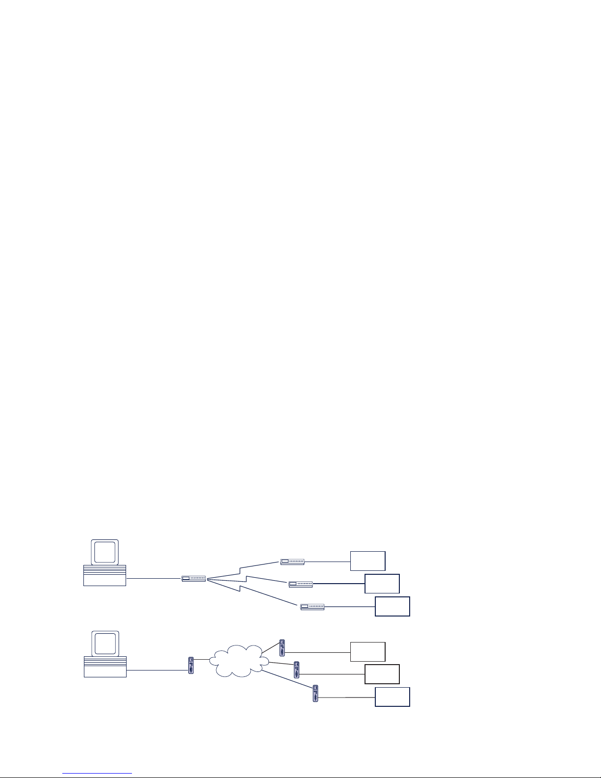
Introduction
The LAN-Modem permits devices that require dial-up
modems for communicating to use the Intranet or
Internet instead of the telephone system. On a serial
interface, the LAN-Modem behaves in a way this is
compatible with standard modems for the telephone
system; the only difference is that the dial-up number is
replaced by an IP address.
Modem
Intranet /
Internet
“ATDT <Tel. No.>”
RS232
RS232
RS232
RS232
before:
LAN Modem
LAN Modem
RS232
“RING”
now:
serial
device
serial
device
serial
device
RS232
Modem
Modem
Modem
RS232
“RING”
serial
device
serial
device
serial
device
“ATDT <IP. No.>”
RS232

4
W&T
Contents
1 Quick Installation 7
1.1 Installation in flow chart form 8
2 Connections and Displays 9
2.1 Ethernet connection 10
2.2 The RS232 connection 12
2.3 Supply voltage 13
2.3.1 5V supply voltage (58210, 58220) 13
2.3.2 12–24V supply voltage (58611, 58620) 13
2.4 LED displays 14
3 TCP/IP Configuration 15
3.1 Assigning the IP using the „ARP“ command 16
3.2 Assigning the IP through the serial port 18
3.2.1 Serially deactivating the DHCP-/BOOTP-Client 19
3.3 Assigning the IP using an RARP server 20
3.4 Assigning the IP using DHCP-/BOOTP protocol 21
3.4.1 Deactivating the DHCP-/BOOTP protocol 22
3.5 Configuring the subnet mask and gateway 24
4 Modem Operation 27
4.1 Serial transmission parameters 28
4.2 Command syntax 29
4.3 Command and data mode 30
4.4 All AT commands 31
4.4.1 A (ATA) 32
4.4.2 D (ATD[IP address]) 33
4.4.3 E (ATE[0|1]) 36
4.4.4 H (ATH) 36
4.4.5 In (ATI[0–8]) 36
4.4.6 O (ATO) 37
4.4.7 Q (ATQ0|1) 37
4.4.8 Sn? (ATS[0-40]?) 37
4.4.9 Sn=x (AT[0–40]=[0–255]) 38
4.4.10 Vn (ATV[0|1]) 39
4.4.11 Zn (ATZ[0|1]) 40
4.4.12 &C (AT&C[0|1]) 40
4.4.13 &D (AT&C[0|1|2|3]) 41

5
W&T
Subject to error and alteration
4.4.14 &Fn (AT&F[0|1]) 41
4.4.15 &K (AT&K[0|3|4|5|6]) 42
4.4.16 &Sn (AT&S[0|1]) 43
4.4.17 &Vn (AT&V[0|1|2]) 43
4.4.18 &Wn(AT&W[0|1]) 44
4.4.19 &Yn (AT&Y[0|1]) 44
4.4.20 &Zn=x (AT&Z[0|1|2|3]=[IP address]) 45
4.4.21 %Bn (AT%B[2-8]) 45
4.4.22 %Dn (AT%D[7|8]) 46
4.4.23 %Pn (AT%P[0|1|2]) 46
4.4.24 %Sn (AT%S[1|2]) 47
4.4.25 %Nn (AT%N[0|1]) 47
4.4.26 ** (AT**) 48
5 Firmware-Update 49
5.1 Where do I get the latest firmware? 50
5.2 Serial update of the AT command interpreter 51
5.3 Network update of the AT command interpreter 52
Example with Telnet client under Windows 95/98/NT 52
5.4 Updating the TCP/IP-Stack 54
Appendix 57
Reading/Sending Configuration Profiles 58
The Modem Protocol on the TCP Level 59
Virtual Modem Ports under Windows NT/2000/XP 60
Technical Data 61
Declaration of conformity 62

6
W&T

7
W&T
Subject to error and alteration
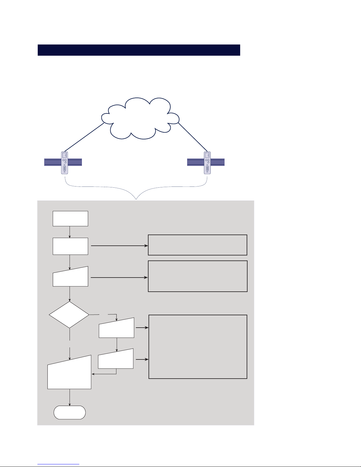
1 Quick Installation
■ LAN-Modem installation in flow chart form
8
W&T Schnellinstallation
1.1 Installation in flow chart form
The following diagram shows the essential installation
steps for any LAN-Modem installation.
LAN-Modem
Intranet /
Internet
Ethernet
LAN-Modem (x)
Standortwahl
Anschluß der
Hardware
Verbindung
über Router /
Bridge ?
nein
ja
Einstellung der
IP-Adresse
ENDE
Modemanwendung
bzw. ser. Gerät:
Ersatz der Tele-
fonnummer durch
IP-Adresse
Einstellung des
Gateways
Einstellung der
Subnet-Mask
1.) Telnet-Session auf den Konfigurationsport des LAN-Modem:
Telnet [LAN-Modem] 1111
2.) Menüpfad Subnet-Mask-Konfiguration :
-> 2 SETUP System
-> 2 Setup TCP/IP
-> 2 Subnet Mask -> [neue Subnet Mask]
3.) Menüpfad Gateway-Konfiguration:
-> 2 SETUP System
-> 2 Setup TCP/IP
-> 3 Gateway -> [Router-IP-Adresse]
- Anschluß der Spannungsversorgung
- Netzwerk-Anschluß über Patchkabel
- Verbindung der seriellen Schnittstellen
1.) Statischer Eintrag in ARP-Cache eines
Rechners im selben Subnet:
arp -s [IP-Adresse] [Ether.-Adr. LANModem]
2.) ping [IP-Adresse]

9
W&T
Subject to error and alteration
2 Connections and Displays
■ Pin Assignments
■ Supply Voltage
■ LED displays

10
W&T Connections and Displays
2.1 Ethernet connection
The location of the LAN-Modem must be selected such that
on the network side a maximum cable length of 100 meters
is not exceeded.
For the network connection, an IEEE 802.3 compatible
terminal on a shielded RJ45 plug is provided on the front
panel. With a shielded patchcable the LAN-Modem can be
connected through here to a hub or switch. Pin assignments
conform to a standard MDI interface (AT&T258), so that you
can use here a 1:1 cable with a length of max. 100 meters.
1 = Tx+
2 = Tx-
3 = Rx+
4 = nc 5 = nc
6 = Rx-
7 = nc
8 = nc
RJ45-Buchse (Belegung AT&T256)
Depending on the LAN-Modem model, the following
standards are supported:
10BaseT (Typ 58210, 58610)
These devices operate conformal with the 10BaseT
standard at 10MBit/s. It is also possible however to link
into a 100BaseTx network using an autosensing hub or
switch. Such an autosensing component automatically
adjusts to the transmission rates supported by the
terminal device.
10/100BaseT autosensing (Models 58220, 58620)
These devices support both 10BaseT as well as the
100BaseTx standrad at a bit rate of 100Mbit/s and offer
full-duplex transmission. Switching between the two
network speeds is done using the autosensing function
of the LAN-Modem according to the capabilities of the
hub or switch used. The prerequisite for operating at

11
W&T Connections and Displays
Subject to error and alteration
100MBit/s is appropriate cabling (Cat 5/ISO Class D or
better).
The current link status is indicated by the Error LED on
the front panel: If it blinks at 1-2 second intervals, there
is no connection to the hub, or the connection is faulty.

12
W&T Connections and Displays
2.2 The RS232 connection
The pin assignments for the RS232 port are identical with
that of a dialup modem, which means that standard cable
can be used. Make sure that the prots for the LAN-Modem
and the serial terminal device are configured for identical
transmission parameters and handshake procedures.
RS232 Pin assignment and function, DB9 female
RS232, DB9 female
1 = NC
2 = TxD
3 = RxD
5 = GND
4 = DSR
8 = RTS
NC
7 = CTS
6 = DTR
The following table shows the factory configured
functions for the individual signals. These can be
modified using the respective AT commands.
Factory setting
Active for existing connection
Data output
Data input
If deactive, break connection and do not
accept new connection until active again
---
Always active
Hardware handshake input
Data output only when active
Hardware handshake output
active = ready to receive data
deactive = not ready to receive data
For incoming connection alternately 1s
active, 4s deactive until connection is
established; then deactive
Direction
Output
Output
Input
Input
---
Output
Input
Output
Output
Pin
1
2
3
4
5
6
7
8
9
AT command
AT&Cn
---
---
AT&Dn
AT&Sn
AT&Kn
AT&Kn
---

13
W&T Connections and Displays
Subject to error and alteration
2.3 Supply voltage
Depending on the hardware version, the LAN-Modems are
supplied either with a regulated +5V or with an AC/DC
voltage of between 12V and 24V.
2.3.1 5V supply voltage (58210, 58220)
The supply voltage for models 58210 and 58220 is
brought in through the power terminal located on the
underside of the housing. The supply voltage is 5V +/5%. The current consumption of the various models can
be found in the technical appendix.
2.3.2 12–24V supply voltage (58611, 58620)
The supply voltage for models 58610 and 58620 can also
be brought in through the power terminal for jack plugs
located on the housing underside. Both DC voltage of any
polarity as well as AC voltage may be used. Polarity
versal protection results in the following maximum and
minimum values for the supply voltage:
AC: 9Veff (-5%) – 24Veff (+5%)
DC: 12V (-5%) – 34V (+5%)
The current consumption of the various models can be found
in the technical appendix.

14
W&T Connections and Displays
2.4 LED displays
Status and error information is indicated by the LAN-Modem
using three LEDs having various blink codes.
• Power-LED
Indicates the presence of supply voltage. If the LED is
not full on, please check your power supply
connections.
• Status-LED
Flashes when there is network activity with the LANModem. Periodic flashing indicates that the port has
a connection to another station.
• Error-LED
The error LED uses various blink codes to indicate
error states on the device or serial port:
1 xflashing = Check network connection
The LAN-Modem is not receiving a link pulse from
a hub. Check the cable and hub.
2 x fhashing = Check serial basic configuration
Use the Telnet configuration to check the basic
settings of the LAN-Modem for Port 0:
SETUP Port 0 (serial) r UART Setup r Baud = 57600
SETUP Port 0 (serial) r UART Setup r Parity = NONE
SETUP Port 0 (serial) r UART Setup r Data Bits = 8
3 x flashing = Check serial basic configuration
Use the Telnet configuration to check the basic
settings of the LAN-Modem for Port 0:
SETUP Port 0 (serial) r UART Setup r Handshake = HARDWARE
All LEDs on = Self-test error
The self-test performed after each start or reset of
the LAN-Modem could not be correctly finished due
for example to an incomplete update of the
firmware. In this state the LAN-Modem is no longer
operational. Please return the unit for repair.
i
For additional
informatio on the
settings, please refer
to section 4 „Modem
Operation“

15
W&T
Subject to error and alteration
3 TCP/IP Configuration
Following the hardware installation, this section describes the logical
integration of the LAN-Modem into the TCP/IP network.
■ Assigning the IP address
■ Setting the Subnet-Mask and Gateway
You can obtain all the parameters from the system administrator of
your network. In contrast to the IP address, which is always required,
you may skip the setting of the subnet mask and gateway if the
communications partner for the LAN-Modem is located in the same
network.

16
W&T TCP/IP Configuration
3.1 Assigning the IP using the „ARP“ command
1
This method can only be used if the LAN-Modem does
not yet have an IP address, i.e. the current entry is
0.0.0.0. To change an IP address, use one of the other
methods described in this section or use the configuration
menu via TELNET.
The prerequisite is a computer located in the network
segment of the LAN-Modem and which has TCP/IP
protocol installed. Read the Ethernet address of the LANModem off from the sticker on the side of the housing:
58xxx [Model]
EN=00c03d004a05
OK xxxxxx
Ethernet address
Now use the following command line of the ARP table in
your computer to add a static entry:
arp -s [IP address] [MAC address]
Example under Windows:
arp -s 172.16.231.10 00-C0-3D-00-12-FF
Example under SCO UNIX:
arp -s 172.16.231.10 00:C0:3D:00:12:FF
Then use the following command line under Start
→
Run
to start a Telnet session to the configuration port of the
LAN-Modem with the desired IP address:
telnet 172.16.232.10 1111 [Return]
1
In Windows environments you must enter the IP
address without leading zeros. Otherwise the entry
will be improperly interpreted by the system and the LANModem will assign an incorrect IP address.
i
Older Windows
systems will only
accept a static entry
if a dynamic entry
was already present.
First send a PING to
another network
station.

17
W&T TCP/IP Configuration
Subject to error and alteration
i
Every IP address must
be used only once in
the network.
The LAN-Modem accepts the IP address of the first network
packet sent to it as its own and saves it in non-volatile RAM.
Only now is the Telnet connection established and the
configuration menu shown in the Telnet window. Now you
may sete the subnet mask and gateway (see section 3.5
Configuring the subnet mask and gateway).

18
W&T TCP/IP Configuration
3.2 Assigning the IP through the serial port
After the LAN-Modem has been reset, a time window of
approx. 1-2 seconds is provided during which you can
assign a new IP address by entering at least three „x“.
1
In contrast to the previously described using ARP,
this serial path works regardless of whether the
LAN-Modem already has an IP address or not. The
procedure can be repeated as often as desired. This
method is therefore recommended if you do not know the
IP address or have forgotten it.
First connect the serial port of the LAN-Modem to a
computer. For a standard PC or a laptop, you will require
a 1:1 modem cable (see section 2.2 The RS232 connection).
The serial transmission parameters of the terminal program
used are configured for 9600 Baud, no Parity, 8 bits, 1 stop
bit, no handshake. Interrupt the supply voltage to the LANModem to perform a reset. If the green Status LED comes on,
enter the letter „x“ at least three times on the terminal until
the LAN-Modem has returned the prompt „IPno.+<Enter>:“.
Use the usual format (xxx.xxx.xxx.xxx) to enter the IP
address and finish your entry by pressing <Enter>. If the
entry was accepted, this is acknowledged with the
assigned IP address. Otherwise a „FAIL“ message is
returned with the last current IP address.
All other settings such as the gateway address, subnet
mask, etc. are made using the Telnet configuration menu
(see section 3.5 Configuring the subnet mask and gateway).

19
W&T TCP/IP Configuration
Subject to error and alteration
3.2.1 Serially deactivating the DHCP-/BOOTP-Client
The DHCP-/BOOTP function of the LAN-Modem can be turned
off when serially assigning the IP address. We recommend
doing this in all cases where it is not absolutely necessary to
use DHCP/BOOTP to assign the IP.
To deactivate the DHCP-/BOOTP client, attach the option „-0“
directly after the IP address (no spaces) and confirm your
entry with <Enter>.
Example:
xxx -> Com-Server
IP no.+<ENTER>: <- Com-Server
172.17.231.99-0 -> Com-Server
172.17.231.99 <- Com-Server
You can always reactivate the function later using the
Telnet configuration under SETUP System
r SETUP TCP/IP r
BOOTP Client.

20
W&T TCP/IP Configuration
3.3 Assigning the IP using an RARP server
UNIX environments in particular often use the RARP protocol
for centralized assignment of IP addresses. This means that
TCP/IP devices that want to obtain an IP address send RARP
requests with their Ethernet address as a broadcast over the
network.
Activate the RARP server on the UNIX system and enter in
the file /etc/ethers the Ethernet address of the LAN-Modem,
and in the file /etc/hosts enter the IP address.
58xxx [Model]
EN=00c03d004a05
OK xxxxxx
Ethernet address
The LAN-Modem must be located in the same subnet as the
RARP server.
Example:
Your LAN-Modem has MAC address EN= 00C03D0012FF
(sticker on the unit). You want to give it IP address
172.16.231.10 and the alias name WT_1:
• Entry in the file /etc/hosts:
172.16.231.10 WT_1
• Entry in the file /etc/ethers:
00:C0:3D:00:12:FF WT_1
If the IP address for the LAN-Modem is 0.0.0.0 (=Factory
Defaults), RARP broadcasts are cyclically generated in
order to obtain a valid address from any existing RARPDaemon.
If the Com-Server already has a valid IP address, an RARP
broadcase is generated after every reset. If a reply comes
within 500ms, the IP addressed contained in it is
accepted. As in the case of assigning through the serial
port, this method also makes it possible to overwrite a
current IP address.

21
W&T TCP/IP Configuration
Subject to error and alteration
3.4 Assigning the IP using DHCP-/BOOTP protocol
Many network use DHCP (Dynamic Host Configuration
P rotocol) or BOOTP for centralized and dynamic
assignment of IP addresses. As far as the LAN-Modem is
concerned, it makes no difference which of the two
protocols is used, since DHCP is only a downwardcompatible expansion of BOOTP. DHCP servers thus also
use requests from BOOTP clients. The following
parameters can be assigned to the LAN-Modem using
these protocols
• IP address
• Subnet mask
• Gateway address
It is not possible to transfer other parameters or lease
time.
Function
To obtain an IP address, the LAN-Modem sends a
corresponding BOOTP request as a broadcast over the
network after each new start. The resulting reply from
the DHCP/BOOTP server contains in addition to the IP
address also the subnet mask and gateway address. The
LAN-Modem immediately loads this information into its
non-volatile memory.
To start up the LAN-Modem in DHCP/BOOTP networks,
consult with your systems administrator. If you are
assigning the address using DHCP, please indicate that
a reserved IP address is needed. For the purpose of
maintaining the respective address database, the
administrator will need the Ethernet address of the LANModem, which can be found on the sticker located on the
housing:
58xxx [Model]
EN=00c03d004a05
OK xxxxxx
Ethernet address

22
W&T TCP/IP Configuration
After the administrator has made the necessary entries, the
LAN-Modem will automatically obtain the desired IP address
after each reset. To ensure the availability of the LAN-Modem even should the DHCP/BOOTP server fail, the previous
IP address is kept if no reply comes.
1
In DHCP environments the IP address to be assigned
must be reserved by means of a fixed link to the
Ethernet address of the LAN-Modem. Under Windows NT this
is done in the DHCP manager under the menu item Reservations. Linux provides the file dhcpd.conf for this purpose, in
which a corresponding entry must be added.
3.4.1 Deactivating the DHCP-/BOOTP protocol
A DHCP server assigns IP addresses dynamically from an
address pool provided by the administrator. This means
that DHCP-compatible devices usually receive another IP
address after starting. Since a constantly changing IP
address is not something you want to have with the LANModem, the latter uses BOOTP protocol, which is based
on fixed Ethernet-to-IP address assignments. DHCP
servers should reply to BOOTP requests only if they have
an explicit IP reservation for the Ethernet address of the
sender.
Some DHCP servers (e.g. Windows 2000 servers) however
use both DHCP and BOOTP requests from their dynamic
address pool. To prevent the LAN-Modem from being
assigned unknown IP addresses in such environments,
the following options are available:
• A reservation must be made in the respective DHCP
server before connecting the LAN-Modem to the
network.

23
W&T TCP/IP Configuration
Subject to error and alteration
• The serial port is used to assign the IP address for the
LAN-Modem. By sending „xxx“ to the LAN-Modem during
a restart, you arrive at the input mode for a new IP
address. If you enter this followed by the string „-0“, the
BOOTP client of the LAN-Modem will be deactivated (see
section 3.2 Assigning the IP through the serial port).
In existing systems the BOOTP client of the LAN-Modem can
also be deactivated and activated whenever desired using the
Telnet configuration under „SETUP System
r SETUP TCP/IP r
BOOTP Client.
For an explanation of the basic terms and concepts for
addressing in the Internet, as well as information about
DHCP and BOOTP, please see our manual „TCP/IPEthernet and WEB-IO“.
i
Older Windows
systems will only
accept a static entry
if a dynamic entry
was already present.
First send a PING to
another network
station.

24
W&T TCP/IP Configuration
3.5 Configuring the subnet mask and gateway
When working in routed environments, the LAN-Modem must
be told the responsible router in addition to the subnet
mask which is valid for the respective network segment.
Valid values for both parameters can be obtained from your
systems administrator. The LAN-Modem provides a Telnet
configuration menu under port number 1111 for entering
this.
Under Windows 95/98/NT the Telnet client is started under
Start
r Run ... using the following command line:
telnet [IP address LAN-Modem] 1111
If the Telnet client is already active, you can establish a
connection under Connect
r Remote-System... . In the field
Host-Name enter the IP address and next to Port enter 1111.
If a connection could be established, the LAN-Modem will
display the following menu on your monitor:
****************************
* MINI Com-Server *
***************************
1. INFO System
2. SETUP System
3. SETUP Port 0 (Serial)
4. SAVE Setup

25
W&T TCP/IP Configuration
Subject to error and alteration
The entry fields for the subnet mask and the gateway
address are reached through the following menu path:
3. SETUP Port 0
Always save using
"SAVE Setup"
in order to activate
the new settings!
1. INFO Com Server
2. SETUP System
4. SAVE Setup
2. Set Password
3. Flash Update
4. Factory Defaults
5. Reset
Takes the selected parameters and saves all
settings in non-volatile memory (EEPROM)
of the LAN-Modem
1. Setup TCP/IP
1. IP-Address
2. Subnet Mask
3. Gateway
4. MTU (512-1024)
Once the settings have been made, they must be loaded into
the non-volatile memory of the LAN-Modem by selecing 4.
SAVE Setup. Then you may close the Telnet session.
The network-side configuration of the LAN-Modem is now
complete. You can PING to check whether all the settings
have been correctly made. In routed environments, the
LAN-Modems must also be reachable by other IP
networks that are incorporated into the infrastructure.

26
W&T

27
W&T
Subject to error and alteration
4 Modem Operation
After the netework configuration is complete, the LAN-Modem
behaves on the serial side just like a dial-up modem with an AT
command set, except that the TCP/IP LAN takes the place of the
telephone line. As far as the controlling application or controlling
device is concerned, all that needs to happen is that the previously
used telephone number is replaced by the IP address of the distant
terminal.
■ Serial transmission parameters
■ Command syntax
■ List and explanation of all AT commands

28
W&T Modem Operation
4.1 Serial transmission parameters
Unlike modems for the telephone network, the LAN-Modem is not able to automatically detect the baud rate of
the terminal. The following transmission format is
factory set:
Baud: 9600
Data bits: 8
Parity: none
Stop bits: 1
Flow control: RTS/CTS
The AT commands AT%Bn, AT%Dn, AT%Pn and AT%Sn
can be used to select the following alternate
transmission speeds and character formats:
Baud: 1200, 2400, 4800, 9600, 19200,
38400, 57600
Data bits: 7, 8
Parity: none, even, odd
Stop bit:s 1, 2
For additional information, refer to the detailed
description of the respective AT command.

29
W&T Modem Operation
Subject to error and alteration
4.2 Command syntax
The LAN-Modem accepts all the AT described in the
following sections as long as they corresponding to one
of the following patterns and are finished with a CR:
letter [number]
& letter [number]
% letter [number]
\ letter [number]
Non-supported AT commands, such as %V or L2 have no
effect and are simply ignored. Invalid commands on the
other hand generate an error message and in particular
end processing of the current command line. Example:
„AT&C0*H0Q1" would run command &C0 , but not Q1,
since the line is no longer considered starting with the
invalid command *H0.

30
W&T Modem Operation
4.3 Command and data mode
The LAN-Modem distinguishes on the serial side between two
mode states: command and data mode.
• Command mode
In this mode, which is activated after power-on, the
AT command interpreter operates on the serial
interface. The LAN-Modem is in this state ready to
receive and process AT commands. All data not
corresponding to AT syntax is ignored or
acknowledged with an error message. Nothing is
passed on to any communications partner in the
network. The command ATO can be used to switch
from command to data mode during any existing
network connection.
• Data mode (Online mode)
This mode is onlyh available while there is a
connection to a communications partner. The AT
command interpreter is now deactivated and all
incoming serial data are passed into the network
without any further processing. To switch back into
command mode, use the escape sequence „+++“. To
retain the binary transparency of data mode inspite of
the processing of this character string, the LAN-Modem only carries out the change if the following times
are observed:
minimum 1s no data received
r
Escape sequence r
1s no data received
If this procedure should be unusable in sepcial cases,
the S registers 2 and 12 can be used to modify the
Escape characters as well as the pause time (see
command Sn=x). As an alternative to use of the
Escape sequence, the RS232 input DTR can be
configured for switching into command mode. FOr
details, see the description of the AT command &Dn.

31
W&T Modem Operation
Subject to error and alteration
4.4 All AT commands
The LAN-Modem accepts all the commands in the table
whose processing is done according to the following
rules:
Befehl
Dx
A
O
H
Zn
En
Qn
Vn
In
Sn?
Sn=x
&Cn
&Sn
&Dn
&Kn
&Fn
&Vn
&Wn
&Yn
&Zn=x
%Bn
%Dn
%Pn
%Sn
%Nn
**n
Beschreibung
IP-Adresse anwählen und online gehen
Ankommenden Ruf annehmen
Zu einer bestehenden Verbindung zurückkehren
Verbindung beenden
Verbindung beenden und Modem zurücksetzen
lokales Echo ein|aus
Ergebniscodes unterdrücken ein|aus
Ergebniscodes als Text statt als Zahl
Firmwareinformation
S-Register auslesen
S-Register ändern
DCD nur bei Verbindung aktiv ein|aus
DSR nur im Online-Modus aktiv ein|aus
Funktion des DTR-Eingangs
Flußkontrolle zwischen Modem und Terminal
Werkseinstellungen wiederherstellen
Konfigurationsprofile/Verbindungsdaten anzeigen
Konfiguration im nichtflüchtigen Speicher ablegen
Standardprofil, das beim Einschalten aktiv ist
Ziel-IP (Telefonnummer) speichern
Baudrate zwischen Modem und Terminal
Anzahl der Datenbits zwischen Modem und Terminal
Paritätsbit zwischen Modem und Terminal
Anzahl der Stopbits zwischen Modem und Terminal
Fernwartung über Netzwerk erlauben
Firmware-Update starten
Parameter
IP-Adresse
---
---
---
n=0, 1
n=0, 1
n=0, 1
n=0, 1
n=0 - 8
n=0 - 40
n=0 - 255
n=0, 1
n=0, 1
n=0, 1, 2, 3
n=0, 3, 4, 5, 6
n=0, 1
n=0, 1, 2
n=0, 1
n=0, 1
n=0, 1, 2, 3
n=2 - 8 (5)
n=7, 8
n=0, 1, 2
n=1, 2
n=0, 1
n=0, 1

32
W&T Modem Operation
• No other command may follow A, D, O, Z and &Z in the
same command line. In the case of A, O and Z they are
ignored, and in the case of D and &Z they are considered
as part of the dialed number.
• Omitting a numerical parameter has the same effect
as indicating a 0.
• The boldface parameters are the standard values that
are created by AT&F.
In addition to these commands, A/ (without a preceding
AT or concluding <cr>) is accepted as an entry to
completely repeat the last command line again.
4.4.1 A (ATA)
= accept incoming call
If the serial application detects an incoming call by
means of the RING sequences send by the LAN-Modem,
the call can be picked up by sending this command. After the network connection with the communication
partner has been established, the LAN-Modem sends the
message „CONNECT“ over the serial interface and
automatically switches to data mode.
Along with each serial output of the „RING“ character
string, an incoming connection request causes the
interface signal RI (=Pin 9) to be set high for approx. 1s.

33
W&T Modem Operation
Subject to error and alteration
4.4.2 D (ATD[IP address])
= Dial command
The dial command is required for establishing a
connection with another LAN-Modem. Taking the place of
the dial-up number used in telephone networks is the IP
address of the desired LAN-Modem. To maintain
compatibility with existing modem applications, the LANModem accepts here the following formats:
D [Options] IP address [;]
D [Options] S=n [;]
DL [;]
• Options
Options may consist of any number of letters and
special characters; these characters have no effect on
the connection set-up. By this means it is possible to
continue using an application that employs at this
point for example a „T“ for using tone dialing.
• IP address
The IP address consists of four numbers between 0
and 255 in decimal format. These can be separated by
special characters (e.g. decimal point or comma).
Without separators it is assumed that each number
consists of exactly three digits. If additional digits
follow behind the last number, these are intereted as
TCP port numbers. If no port number is specified, port
number 8000 is implied. Valid entries would include
for example.:
172016232073
1720162320738000
172.16.232.73
172.16.232.73:8000

34
W&T Modem Operation
• S=0|1|2|3
The LAN-Modem has a non-volatile memory for up to four
destination IP addresses. By specifying a value between
0 and 3, the IP addresses stored here is used for the call
set-up. If only „S“ is entered without a numerical value,
the addresses stored in position 0 is used. The command
&Zn is used to write to the non-volatile address memory.
• L
When using „L“ instead of the IP address, the dial-up
is repeated using the last used values. If no address
has been dialed since the last reset of the LAN-Modem, the message „ERROR“ is returned.
• ; (Semicolon)
Entering a semicolon to terminate the dial-up command
causes the LAN-Modem not to automatically return to
data mode after a successful call set-up, but rather to
remain in command mode.
Example of dial-up command:
ATD172.16.1.1
ATD172016001001
ATDT172.16.001.001
All three commands have the same effect: An attempt is
made to set up a call to the LAN-Modem having IP
address 172.16.1.1.

35
W&T Modem Operation
Subject to error and alteration
Replies for the dial-up command
• CONNECT
The network connection with the desired destination
system was successfully made, and the serial
application connected therre accepted the call. If the dialup command was not terminated with a semicolon, the
LAN-Modem is now in data mode, i.e. all entries are sent
transparently to the communication partner
• NO CARRIER
The network connection to the desired
communication partner was able to be established,
but the serial application there did not pick up the
call. The time for which the LAN-Modem waits for the
counterpart to pick up the call is stored in Register S7
and is factory set to 50s.
• BUSY
No network connection to the desired communication
partner could be established. The cause of this may
be a station that is already busy with another
connection. In this case the attempt to establish a
connection is rejected. Another reason may be an
unreachable or incorrect IP address. For very slow
network routs to the destination system, the timeout
stored in Register S6 for the TCP connection set-up can
be set to a higher value. The factory setting is for 3s

36
W&T Modem Operation
4.4.3 E (ATE[0|1])
= local echo off|on
This command determines whether the data received on the
RS232 interface in command mode should lbe returned. The
factory setting is for echo on.
ATE0 = Echo off
ATE1 = Echo on
4.4.4 H (ATH)
= Quit connection
This command quits the connection. Both serial
communication partners receive the reply „NO CARRIER".
4.4.5 In (ATI[0–8])
= Read out firmware information
The I command is used to read out system information
for the LAN-Modem. Of a possible 0-8, only parameters 0
and 3 are presently used. The remaining even options are
reserved for later enhancements.
• ATI0
Returns product code „58210" from the LAN-Modem
• ATI8
Returns the firmware version of the AT command
interpreter

37
W&T Modem Operation
Subject to error and alteration
4.4.6 O (ATO)
= Switch to data mode
This command switches (when there is an existing
connection) from command to data mode. If you need for
example to change LAN-Modem parameters during a
connection, you must first use the Escape sequence to
switch to command mode. After the desired
reconfiguration you can then use the ATO command to
reactivate data mode.
For additional information: Section 4.3 „Command and
Data Mode"
4.4.7 Q (ATQ0|1)
= Modem replies on|off
Default setting: 0 = ON
Replies generated by the LAN-Modem such as „OK“ or
„CONNECT“ can be turned off by using the Q command:
• ATQ0
The LAN-Modem sends replies
• ATQ1
Reply messages are turned off.
4.4.8 Sn? (ATS[0-40]?)
= Read S register
This command is used to read the 41 S registers that
determine the operating behavior of the LAN-Modem.
Changing or writing to the S registers is done using the Sn=x
command shown below.
!

38
W&T Modem Operation
4.4.9 Sn=x (AT[0–40]=[0–255])
= Set S register
The LAN-Modem has 41 S registers (S0 to S40) which
determine its operating behavior. The command Sn=x is
used to overwrite the current contents, whereby „n“ specifies
the desired register and „x“ the value to write in decimal
format. Only the following registers presently have meaning
for the operation of the LAN-Modem:
Register
S0
S1
S2
S3
S4
S5
S6
S7
S9
S10
S12
S14
S21
S23
S25
S39
Description
Pick up after how many ring characters ? (0=never)
Ring counter
ESC character
Code for CR (Carriage Return)
Code for LF (Linefeed)
Code for BS (Backspace)
Wait time for TCP-connection set-up (seconds)
Waits until other party picks up (seconds)
Time base for carrier generation (1/10 seconds)
Allowed Carrier dropout (1/10 seconds)
Isolation time for ESC sequence (1/50 seconds)
Option bits from commands E, Q, V
Option bits from commands &C, &D, &S
Option bits from commands %B, %N
Allowed DTR-Dropout (1/100 seconds)
Handshake mode (command &K)
Default value
0
43 (=ASCII "+")
13
10
8
3
50
20
50
5
Note the following when writing to the S registers of the
LAN-Modem:
• The command Sn=x has only a temporary effect. The
changes can be loaded into the non-volatile memory
of the LAN-Modem by using the &W command. The
only exceptions are registers S3, S4 and S5. These
cannot be permanently stored.
• Registers S14, S21, S23 and S39 should not be accessed
by direct writing, but rather via the corresponding AT
commands.

39
W&T Modem Operation
Subject to error and alteration
The value of register S9 is adjusted to the value of S10
each time a connection is set up.
4.4.10 Vn (ATV[0|1])
= Result codes in plain text
Default setting: 1 = ON
This command specifies whether result returns from the
LAN-Modem are to be numerical or in plain text. The
following messages and result codes are possible:
0 = OK 1 = CONNECT
2 = RING 3 = NO CARRIER
4 = ERROR 4 = BUSY
• V0
Replies will be numerical in decimal format.
• V1
Replies will be in plain text.

40
W&T Modem Operation
4.4.11 Zn (ATZ[0|1])
= Reset the LAN-Modem
The Zn command quits any active connection and resets the
firmware of the LAN-Modem to the parameters stored in the
non-volatile memory. By specifying „0“ or „1“ you can select
one of the two available reset profiles (see also &Wn
command). Which profile is loaded after the LAN-Modem is
turned on is defined by the &Yn command.
• Z0
Load stored reset profile 0.
• Z1
Load stored reset profile 1.
4.4.12 &C (AT&C[0|1])
= DCD Option
Default setting: 1 = ON
This command defines the behavior of the DCD interface
output:
• &C0
DCD is always active regardless of the network-side
connection status.
• &C1
DCD is only active if there is a connection to a
communication partner.

41
W&T Modem Operation
Subject to error and alteration
4.4.13 &D (AT&C[0|1|2|3])
= Modem response to DTR option
Default setting: 2
Defines the effect of a level change on the DTR input on the
LAN-Modem. One of four functions may be selected:
• &D0
The LAN-Modem ignores the signal.
• &D1
If the LAN-Modem is in data mode,k an ON
r OFF change
places the modem in command mode. The ATO command
can be used to return to data mode.
• &D2
A change from ON
r OFF breaks the existing connection.
A new connection can only be established when an enable
level is present on DTR.
• &D3
Has the same function as &D2 but additionally it resets
the LAN-Modem. If the LAN-Modem is on data mode, a
level change on the DTR input is only recognized if it is
present for the time defined in S-register 25.
4.4.14 &Fn (AT&F[0|1])
= Restore
The LAN-Modem has two factory settings which can be
invoked using the commands AT&F and AT&F1. The
defaults specified by the individual commands refers
basically to the factory profile 0. Factory profile 1 differs
here in the function of the DTR input (&D0 instead of &D2)
and in the flow control (&K0 instead of &K3).

42
W&T Modem Operation
4.4.15 &K (AT&K[0|3|4|5|6])
= Flow control
Default setting: 3 = RTS/CTS
This command determines the flow control between the LANModem and the connected serial device:
• &K0 (no handshake)
Flow control is turned off. The LAN-Modem sends all data
to the serial device regardless of the status of the
handshake input RTS. In the opposite direction the LANModem has no way to report an impending overflow of
its input buffer through the CTS output, so that in this
case the serial applications are responsible for ensuring
data integrity.
• &K3 (RTS/CTS)
Flow control is handled by the port signals RTS and
CTS. The LAN-Modem sends serial data only when
there is an enable level on its RTS input. An
impending overflow of the serial input buffer is signaled
by the CTS output.
• &K4 (Xon/Xoff)
Flow control is handled by the control characters Xon
(hex 11) and Xoff (hex 13), whereby these characters
are filtered out from the user data stream. If the LANModem receives an Xoff, no additional data are sent
to the serial device until the latter has sent an Xon.
The LAN-Modem indicates its ready or not-ready status
likewise using an Xoff or Xon.
• &K5 (transparent Xon/Xoff)
As in the case of &K4 the flow control is handled by
Xon/Xoff. The control characters are now however not
filtered out, but rather sent transparent to the
communication partner.

43
W&T Modem Operation
Subject to error and alteration
• &K6 (RTS/CTS + Xon/Xoff)
Flow control is handled by RTS/CTS and Xon/Xoff. The
modem generates signals for both handshake
procedures and allows itself to be prevented from
continuing to send by means of Xoff or a returned RTS.
4.4.16 &Sn (AT&S[0|1])
= DSR Option Selection
Default setting: 0
This command defines the behavior of the DSR output:
• &S0
The DSR output is always enabled regardless of the
connection status and regardless of the mode
(command or data).
• &S1
DSR is only enabled if the LAN-Modem has an active
connection in data mode.
4.4.17 &Vn (AT&V[0|1|2])
= Display system information
This command causes the LAN-Modem to output its
configuration and connection data:
• &V0
Provides the current configuration data as well as the
data stored in non-volatile profiles 0 and 1. In
addition, the stored destination addresses are output.

44
W&T Modem Operation
• &V1
The LAN-Modem returns statistics for the last TCP/IP
connection.
• &V2
The LAN-Modem sends as a reply its complete
configuration coded in S record format. By sending this
data record to another modem, it is possible for example
to copy configurations over the network.
For additional information, see section 6 „Copying the
configuration data").
4.4.18 &Wn (AT&W[0|1])
= Active Profile Write
This command is used to write the two non -volatile
conofiguration profiles 0 and 1 which the LAN-Modem
provides. The current settings are written to the memory
location defined by „n“. The configuration profiles are
specified by the command Zn. Which of the two profiles
is active after the LAN-Modem is turned on is defined by
the command &Yn.
4.4.19 &Yn (AT&Y[0|1])
= Active Profile Read
This command specifies which of the two configurations
stored in the profiles the LAN-Modem uses after being
turned on or after a reset. Additional information can be
found in the following sections:
Zn: Reset modem to Profile 0 or 1
&V1: Read the configuration profiles
&Wn: Store the current settings in the specified profile

45
W&T Modem Operation
Subject to error and alteration
4.4.20 &Zn=x (AT&Z[0|1|2|3]=[IP address])
= Save destination IP address
The LAN-Modem can save up to 4 destination IP addresses in
its non-volatile memory, which can later be recalled using the
fast dial function (Sn=x) of the dial command.
Example: AT&Z1=172.16.2.2
IP address 172.16.2.2 is stored in memory location 1.
ATDS=1 can now be used to establish a connection with this
address.
4.4.21 %Bn (AT%B[2-8])
= Modem Port Bps Rate
Default setting: 5 (9600 Baud)
This command is used to set the baud rate. The following
speeds are available:
Command
%B2
%B3
%B4
%B5
%B6
%B7
%B8
Baudrate
1200
2400
4800
9600
19200
38400
57600
1
The %B command has a delayed effect. The first OK
reply is still with the old baud rate.
Successive commands in the same command line (such as &W
for saving) are ignored. This ensures that any inadvertent
change in the baud rate can be restored by resetting the
LAN-Modem.

46
W&T Modem Operation
4.4.22 %Dn (AT%D[7|8])
= Number of data bits per character
Default setting: 8
This command determines whether the serial character
format works with 7 or 8 data bits.
1
The %D command has a delayed effect. The first
OK reply is still with the old data format.
Successive commands in the same command line (such as
&W for saving) are ignored. This ensures that any
inadvertent change in the baud rate can be restored by
resetting the LAN-Modem.
4.4.23 %Pn (AT%P[0|1|2])
= Specifying the parity bit
Default setting: 0 = no parity
This command determines if and, if yes, what parity is used
for the serial data format.
• %P0 = no parity
• %P1 = odd parity
• %P2 = even parity
1
The %P command has a delayed effect. The first
OK reply is still with the old data format.
Successive commands in the same command line (such as
&W for saving) are ignored. This ensures that any
inadvertent change in the baud rate can be restored by
resetting the LAN-Modem.

47
W&T Modem Operation
Subject to error and alteration
4.4.24 %Sn (AT%S[1|2])
= Minimum number of stop bits between 2 characters
Default setting: 1= 1 stop bit
This command determines how many stop bits (minimum)
appear between 2 serial characters.
1
The %S command has a delayed effect. The first
OK reply is still with the old data format.
Successive commands in the same command line (such as
&W for saving) are ignored. This ensures that any
inadvertent change in the baud rate can be restored by
resetting the LAN-Modem.
4.4.25 %Nn (AT%N[0|1])
= Remote maintenance over the network allowed
Default setting: 1 = allowed
Loading firmware updates and copying configuration data is
possible either through the serial port or over the network.
To protect against misuse of network-side remote
maintenance, the &N command makes it possible to
suppress this functionality.
Additional information: Section 5 „Firmware-Update" and
Section 6 „Copying Configuration Data"

48
W&T Modem Operation
4.4.26 ** (AT**)
= Start flash update
Updating the firmware or sending a configuration file must
be introduced with the ** command. The LAN-Modem
generates the following message and then expects the
update data in Motorola S Record format. If no data are sent
within 30s, the mode is automatically quit.
MB90F562 bootloader v1.x W&T xx/xxxx
Invoked by software, ESC to cancel
Waiting (Port 0)...
Additional information: Section 5 „Firmware-Update" and
Section 6 „Copying Configuration Data".

49
W&T
Subject to error and alteration
5 Firmware-Update
The firmware for the LAN-Modem is divided into two function
modules whoses update methods differ.
■ Update the AT command interpreter serially or over the network
■ Update the TCP/IP-Stack over the network

50
W&T Firmware-Update
5.1 Where do I get the latest firmware?
The current firmware including the update tool and a
revision list is published on our Web site at the following
address: http://www.wut.de.
Before proceeding with the update, please write down
the 5-digit model number located on the LAN-Modem.
From our homepage you can now find the product
overview sorted by article numbers, from which you
arrive directly at the Web data sheet for the respective
LAN-Modem model. Then follow the link to the current
version of the firmware.
1
Never interrupt the update process by pulling the
power plug or pressing the reset key. The Com-Server will be made inoperable following an incomplete
update.
Never mix files having different version numbers in the
file name. This will make the device inoperable.
Transmit all the files in order. The Com-Server
automatically detects when all the files have been sent
and the new operating software is complete. It will then
automatically perform a reset.

51
W&T Firmware-Update
Subject to error and alteration
5.2 Serial update of the AT command interpreter
For this the LAN-Modem must have a serial connection to a
terminal program whose transmission parameters are
configured as follows:
Baud rate: same as the LAN-Modem
Data format: 8 data bits, no parity, 1 stop bit
Handshake: RTS/CTS (required)
The command AT** is used to place the LAN-Modem in
serial update mode, which is acknowledged with the
following message:
MB90F562 bootloader v1.x W&T xx/xxxx
Invoked by software, ESC to cancel
Waiting (Port 0)...
The function „Send text file" of the terminal program can
now be used to sent the mhx-file with the current
firmware. The LAN-Modem sends a continuous byte
counter during the transmission and returns the
message „OK“ after successful completion of the update.
The new firmware version can now be checked using the
command AT13.
1
You cannot use the binary data transmission
function offered by terminal programs, since this
uses additional protocols such as ZModem or Kermit.
The update mode is protected with a timeout of 30s. If no
data are transmitted within this time, the LAN-Modem
automatically resumes normal operating mode.

52
W&T Firmware-Update
5.3 Network update of the AT command interpreter
Updating the firmware over the network offers the advantage
of a higher speed compared with the serial method. The
prerequisite however is that network-side remote
maintenance be enabled by the command %N1.
After establishing a TCP socket connection to Port 8000 on
the LAN-Modem, the latter returns a short identifier. If this is
replied to within three seconds with the character „U“, update
mode is started with the following message.
MB90F562 bootloader v1.x W&T xx/xxxx
Invoked by software, ESC to cancel
Waiting (Port 1)...
As in the case of a serial update, the LAN-Modem now
expects the update data in S record format. Under
Windows the following method using a Telnet client and
pasting from the clipboard has proven useful.
Example with Telnet client under Windows 95/98/NT
1. Open the mhx file with the LAN-Modem firmware in an
editor and copy the entire contents to the clipboard.
2. From Start
r Run r telnet [IP address] 8000 on a Windows
machine having a TCP/IP stack, the network connection
to the LAN-Modem is established and the message
„Wxxxx" appears.
3. Entering a „U“ within the first three seconds activates
update mode, and the LAN-Modem sends the
corresponding reply.
4. Use Edit
r Paste to copy the firmware from the clipboard
to the LAN-Modem.
5. After a successful update the LAN-Modem breaks the TCP
connection. Any transmission errors are reported with
referenced to a checksum error.

53
W&T Firmware-Update
Subject to error and alteration
1
When starting update mode over the network, the
serially connected device is informed of the access
with a short message.
The update mode is protected with a timeout of 30s. If no
data are transmitted within this time, the LAN-Modem
automatically resumes normal operating mode.
If updating over the network is automated in any way,
you must ensure a pause of at least 0.5 seconds between
sending of othe „U“ and the start of firmware
transmission. The LAN-Modem needs this time to delete
the internal serial receive buffer when switching over to
update mode.

54
W&T Firmware-Update
5.4 Updating the TCP/IP-Stack
Prerequisite is a PC running under Windows 9x/NT/2000
with a network connection and an installed TCP/IP stack.
You need two files for the update process:
1. The Update-Tool (32-bit application for Windows9x/
NT/2000), used to perform the update, and
2. the file with the extension *.bin (e.g. C4r1_0.bin),
which contains the new operating software for the
LAN-Modem. This file is sent to the LAN-Modem.
The update process is described in steps below. Please
follow these instructions exactly. After an incomplete
update the device will no longer be operable!
1. Close all connections that may still be active on the
LAN-Modem. Before the update process all buffers and
their contents are deleted!
2. Start the remote configuration tool of the LAN-Modem
via Telnet
telnet [IP address] 1111
Select the following in the SETUP menu: System
r Flash
Update
r Net Update and confirm with y. The LAN-Modem
closes the Telnet connection, and the green status LED
indicates that it is now in update mode.
3. Now start the update tool. The menu path CS
programming
r Flash takes you to the input screen for
uploading the new firmware.
4. Enter the IP address for the LAN-Modem as well s the
name of the firmware file in the corresponding fields.

55
W&T Firmware-Update
Subject to error and alteration
IN the option field „Output“ please select only the item
„Firmware“.
5. Click on the Start button. The update will take several
secnds. It is only finished when a message window
reports the end of the update process.
6. Check in the configuration menu of the LAN-Modem to
verify that the new operating software was loaded. The
menu INFO System
r SOFTW Date/Rev must now show
the new version number of the firmware.
If the old version is still displayed, the file with the new
operating software is corrupted. Please contact your
dealer for assistance.
1
The procedure described here for the update only
applies to version 1.14 and higher of the TCP/IP
stack. LAN-Modems with a lower version of othe TCP/IP stack
must first be upgraded to 1.14 or higher. Note here that
only the destination IP address and the name of the new
firmware may be entered in the input screen for the update.
In the option field, however, both firmware and
configuration must be activated.

56
W&T

57
W&T
Subject to error and alteration
Appendix
■ Reading and sending complete configuration profiles
■ The modem protocol on the TCP level
■ Using with W&T COM Port Redirector and virtual modem ports
■ Technical Data

58
W&T Appendix
Reading/Sending Configuration Profiles
To simplify the configuration of the LAN-Modem when
using a greater number of devices, it is possible to copy
the configuration data. To do this, you must first
configure a LAN-Modem for the desired operating mode
using the AT commands. In the ext step you use &Wn to
save these configuration data in one of the two nonvolatile profiles. Then use the command &V2 to read the
entire conofiguration in S record format and store it in a
file.
The upload of the configuration data to other LAN-Modems can be done either over the serial interface or over
the network. The procedure is then identical to that
described in Section 5 for updating the AT command
interpreter.

59
W&T Appendix
Subject to error and alteration
The Modem Protocol on the TCP Level
Normally LAN-Modems will be used only to connect to
each other. It is however conceivable that an application
program uses TCP/IP programming to direct dial an
individual LAN-Modem or to be called by the LAN-Modem.
The information required for doing this can be obtained
on request.

60
W&T Appendix
Virtual Modem Ports under Windows NT/2000/XP
As is the case with standard dial-up modems, the LANModems are generally used in pairs, with one LAN-Modem used to dial-up another. If in a serial application this
involves an application running under Windows NTW,
2000 or XP, a LAN-Modem is not required on this side.
The COM Port Redirector for WIndows NTW/2000/XP
allows you to create virtual COM ports with an integrated
AT command interpreter. Whenever an application opens
such a virtual modem port, the latter behaves just like a
local COM port with an externally connected hardware
LAN-Modem. Both incoming and outgoing connectrions
are possible.
Where do I get the COM Port Redirector
The latest version can always be downloaded at no
charge from our Web site under the following address:
http://www.wut.de
Before proceeding with the update, please write down
the 5-digit model number located on the LAN-Modem.
From our homepage you can now find the product
overview sorted by article numbers, from which you
arrive directly at the Web data sheet for the respective
LAN-Modem model. Then follow the link to the current
version of the COM Port Redirector for Windows NT/
2000/XP.

61
W&T Appendix
Subject to error and alteration
Technical Data
typ. 270mA
typ. 455mA
typ. 80mA
typ. 175mA
0 - 60°C
0 - 60°C
0 - 60°C
0% - 95%
105 x 75 x 22mm
ca. 110g
max. 330mA
max. 575mA
max. 110mA
max. 225mA
Spannungsversorgung
Typ 58210:
Typ 58220:
Typ 58610@24V/DC:
Typ 58620@24V/DC:
zulässige Umgebungstemperatur bei
freier Luftzirkulation, nicht angereiht:
Typ 58210, 58220, 58610, 58620:
zulässige Umgebungstemperatur bei
angereihter Montage auf Hutschiene:
Typ 58210, 58610:
Typ 58220, 58620:
zulässige Luftfeuchtigkeit,
nicht kondensierend:
Abmessungen
58210, 58220, 58610, 58620:
Gewicht 58210, 58220, 58610, 58620:

62
W&T Appendix
Declaration of conformity

W&T
 Loading...