


W&T
Manual
Web-Thermometer
Web-Thermo-Hygrometer
Web-Thermo-Hygrobarometer
Web-Thermometer Relay
Web-Thermometer Air Quality
Typ 10/100BaseT, 12-24V
Modell 57713, 57714, 57715
57716, 57718, 57720
Release 1.03, Mar 2016

W&T
© 03/2016 by Wiesemann und Theis GmbH
Microsoft, MS-DOS, Windows, Winsock and Visual Basic
are registered trademarks of the Microsoft Corporation
Subject to errors and changes:
Since we can make mistakes, none of our statements should
be used without checking. Please let us know of any mistakes
or misunderstandings you are aware of, so that we can recognize and eliminate them quickly.
Perform work on and with W&T products only as described
here and only if you have read and understood the manual
fully. Unauthorized use can result in hazards. We are not liable for the consequences of unauthorized use. When in doubt,
check with us or consult your dealer!

W&T
Introduction
The W&T Web-Thermometer contains all functions in a box
to measure, store and display your climate data. Moreover,
the numerous alarm functions are available which can be integrated into your own applications or into available systems.
In this manual you find all information which you need for the
installation, configuration and the use of the Web-Thermometer.

W&T
Content
Introduction ................................................................... 3
1 Quick-Start/Commissioning ........................................ 7
1.1 Connecting the sensor (#57713, #57714, #57715,
#57718, #57720) ............................................................7
1.2 Connecting the PT100/PT1000 sensor and output confi-
guration (#57616) ...........................................................8
2 Online measurement storage inside the W&T Cloud . 14
2.1 Auto connect ................................................................14
2.2 Create a user account ...................................................14
2.3 Assign data by 4-digit access code in the cloud ............15
2.4 Assign measured data via user account in the device ....15
3.1 Configuring network parameters with WuTility ..... 16
3.1.1 Applications and prerequisites ...................................16
3.2 Assigning the IP using DHCP protocol ................... 19
3.2.1 Manual activation of DHCP .........................................19
3.2.2 System name .............................................................20
3.2.3 Lease time .................................................................20
3.3 Assigning the IP using the ARP command .............. 21
3.4 Assigning the IP using the serial port.................... 23
4 Supply voltage .......................................................... 25
4.1 Power over Ethernet ......................................................25
4.2 External supply .............................................................25
5 Ethernet interface ..................................................... 26
5.1 Link status ....................................................................26
5.2 10/100BaseT on RJ45 ...................................................26

5
W&T
6 Connecting the sensor .............................................. 27
6.1 NTC sensor measuring input (#57714) ..........................27
6.2 Pt100/1000 sensor measuring input (#57715) ..............27
6.3 Combined sensor measuring input (#57713, #57720) ..27
7 Configuration Using Web-Based Management ........... 29
7.1 Home ............................................................................29
7.2 Visualization .................................................................30
7.3 Own webpage ...............................................................31
7.4 Login ............................................................................31
8 Basic Settings ............................................................ 33
8.1 Network ........................................................................33
8.2 Sensors .........................................................................34
8.3 Date/Time ....................................................................34
8.4 Language/Infos .............................................................34
8.5 Data storage .................................................................35
8.6 Password ......................................................................35
9 Communication paths ............................................... 36
9.1 Web pages ....................................................................36
9.2 Mail ..............................................................................39
9.3 Cloud............................................................................39
9.4 RSS ...............................................................................39
9.5 SNMP/Syslog .................................................................39
9.6 FTP ...............................................................................40
9.7 Socket access ...............................................................40
10 Alarms/Messages ................................................... 41
11 Diagnosis ................................................................ 43
12 Device information ................................................. 44
13 Maintenance ............................................................ 45
13.1 LED Test .....................................................................45
13.2 Reboot ........................................................................45
13.3 Factory defaults ..........................................................45
13.4 Save configuration ......................................................46
13.5 Restore configuration .................................................46

6
W&T
14 Individual request of measurement values ............. 47
14.1 Request via TCP/IP ......................................................47
14.2 Requesting via UDP .....................................................48
14.3 Requesting via SNMP ...................................................49
15 Firmware Update ..................................................... 52
15.1 Where is the latest firmware available? ........................52
15.2 Firmware update over the network under Windows .....52
16 Hardware-Reset to factory defaults ........................ 54
17 Technical data ......................................................... 55
17.1 Technical data for the articles 57714 and 57715 ........55
17.2 Technical data for the articles 57713 and 57720 ........56
17.3 Technical data for the article 57716 ............................57
17.4 Technical data for the article 57718 ............................58
18 Disposal ........................................................................59
7
W&T
1 Quick-Start/Commissioning
Just a few steps are required to start up your W&T Web-Thermometer and to make it visible in your network.
Power-over-Ethernet
The Web-Thermometers are designed for use in PoE (Powerover-Ethernet) environments in accordance with IEEE802.3af.
Power is provided by the network infrastructure using the
RJ45 terminal. The devices support both phantom power
using data pairs as well as power feed using the unused wire
pairs s. Power Supply).
!
Use of the Web-Thermometer is also possible in networks
without PoE power supply. In this case simply use an
external power supply attached to the screw terminal as
described in the chapter Power Supply. No additional configurations or settings are necessary.
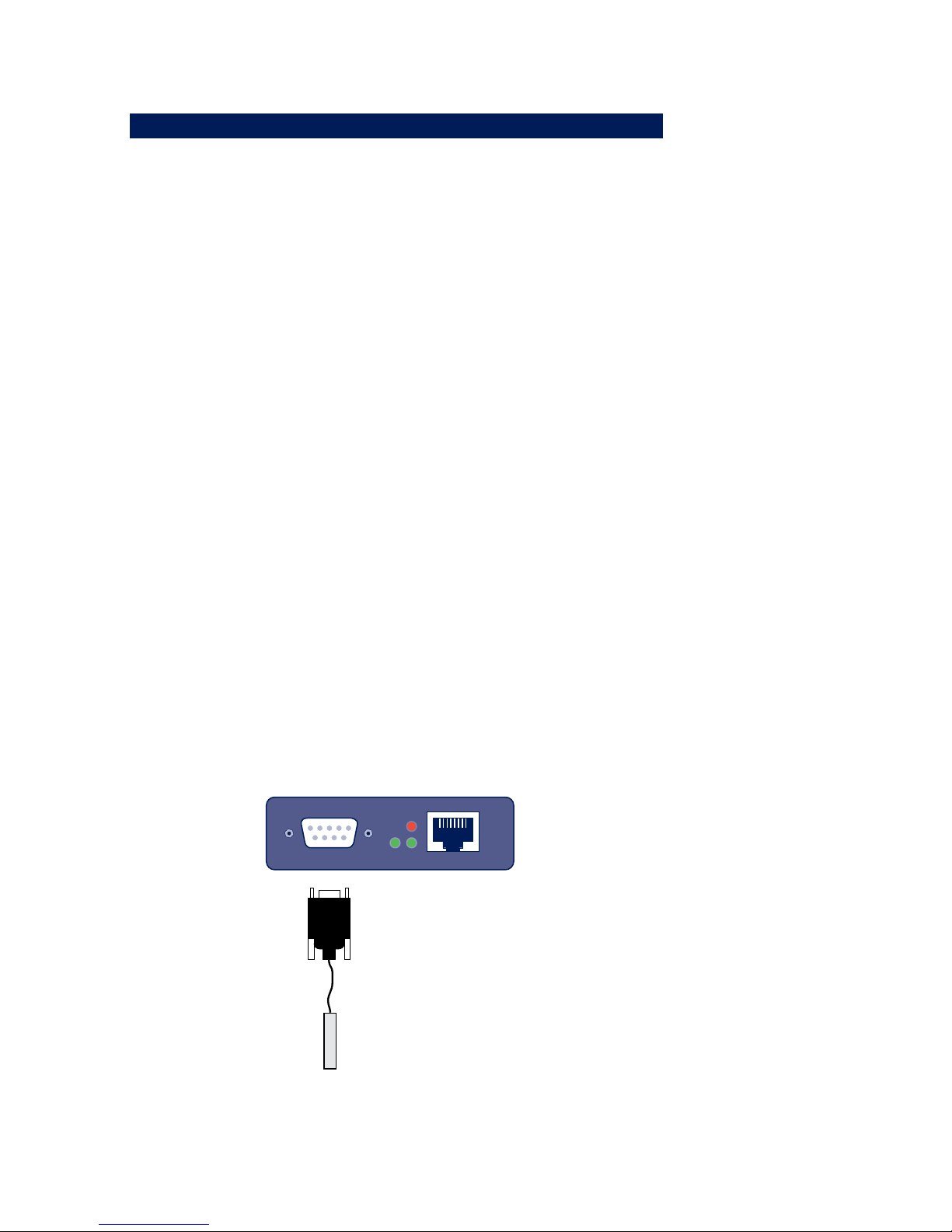
1.1 Connecting the sensor (#57713, #57714, #57715,
#57718, #57720)
8
W&T
Plug the sensor included in the scope of delivery into the
9-pin IO terminal on the unit.
Information for Web-Thermometer Air Quality, #57718:
!
The measuring of the VOC value begins after an initialization time of 15 minutes after powering on the device.
In this time a VOC value of 450ppm will be displayed.
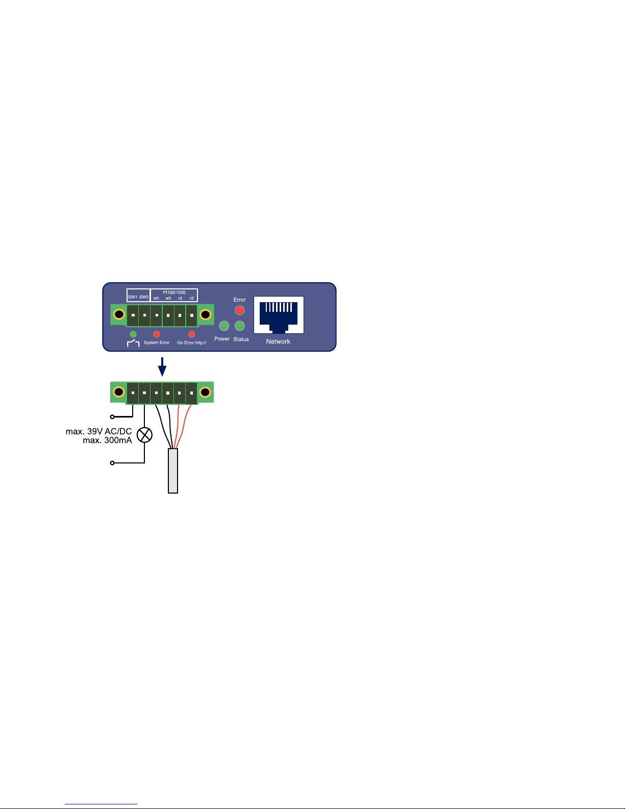
1.2 Connecting the PT100/PT1000 sensor and output
configuration (#57616)
The output of the Web-Thermograph Relay is switched internally using a relay contact (normally open). The consumer
is connected to the screw terminals 1 and 2. The maximum
switchable DC or AC voltage is 39V, with a maximum current
flow of 300mA.
The PT100 or PT1000 temperature sensor is connected to
screw terminals 3, 4, 5 and 6, whereby the wires of the same
color must lie adjacent to each other.
9
W&T
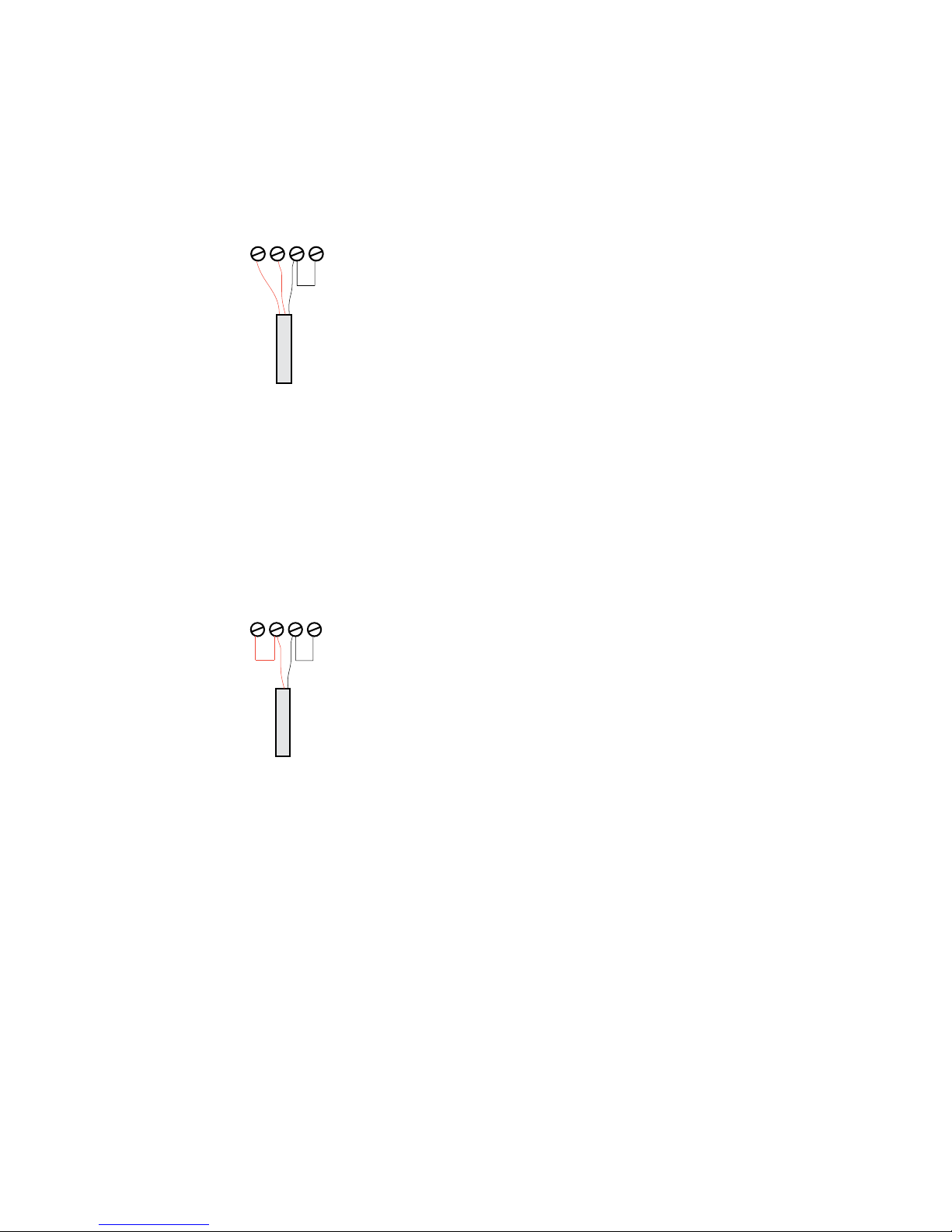
The incoming line to the PT100 4-wire sensor may be of virtually any practical length.
Connecting a PT100 3-wire sensor:
When connecting a PT100 3-wire sensor the same-color wires
are connected to the terminals marked with the corresponding colors. A jumper to the remaining free terminal is required for the single wire.
Connecting a PT100 2-wire sensor:
When connecting a PT100 2-wire sensor, one wire is brought
to the red terminal and the other to the black terminal. Jumpers must be placed here to the free terminals.
10
W&T
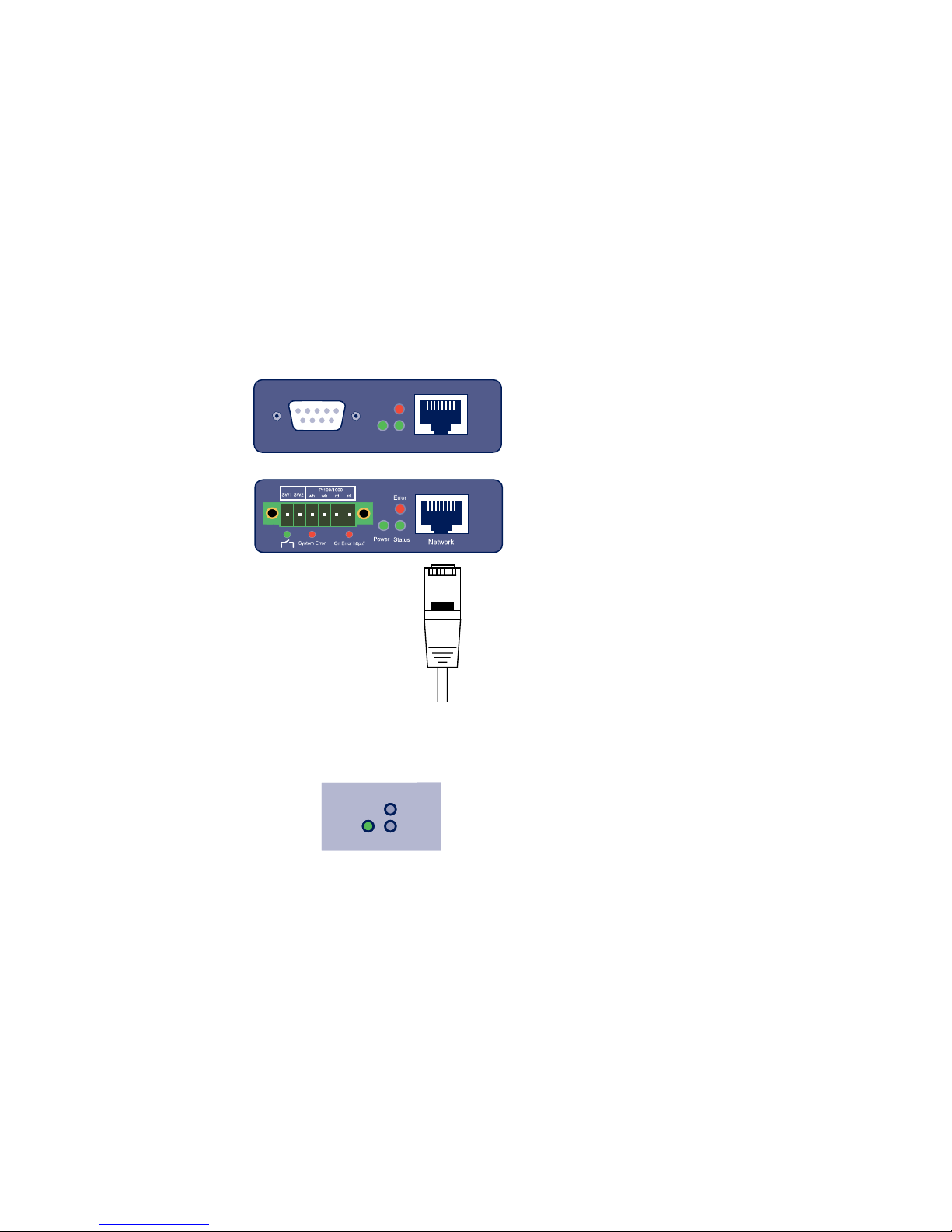
1.3 Ethernet connection (#57713, #57714, #57715,
#57716, #57718, #57720)
The Web-Thermometer incorporates an IEEE802.3-compatible
network interface on a shielded RJ45 connector. The pin assignments correspond to an MDI port, so that the connection
to the hub or switch is accomplished using a 1:1 shielded
patch cable.
1.4 LED-displays
Power Status
Error
Power-LED
OFF: There is no power present. Check the correct connection of the supply (PoE or the external power supply)
ON: Power is present (PoE or the external power supply).

11
W&T
Power Status
Error
Status-LED
Rapid continuous flashing = bootup, no IP
Rapid continuous flashing (approx. 3x/s) indicates that
the device is in the bootup phase and/or has not yet been
assigned an IP address. Please use WuTility for example to
assign the device an IP address.
Slow continuous flashing = connection
Periodic flashing indicates that the port has a valid connection to another network station. After the IP configuration you can open the homepage of the device with a web
browser.
Power Status
Error
Error-LED
The Error-LED shows errors of the device.
All LEDs on = Self-test error
The self-test performed after each start or reset of the
device could not be correctly finished. This error can occur
when you have prematurely broken off a software update
and the full operating software could not be transferred.
The device is no longer capable of being operated in this
condition. Repeat the software update over the network
(see Firmware update), and address the device using its
assigned IP address. If this does not eliminate the error or
should the error occur irrespective of any prior software
update, please return the unit to W&T for service.

12
W&T
Speed
Link/Activity
Speed (yellow)
OFF: Simultaneous illumination/flashing of the Link/Activity LED means there is a link to a device at a rate of 10
MBit/s (10BaseT).
ON: Simultaneous illumination/flashing of the Link/Activity LED means there is a link to a device at a rate of 100
MBit/s (100BaseT).
Speed
Link/Activity
Link/Activity (green)
OFF: The device is not detecting a Link pulse from a hub
or switch. Check the cable or the hub port.
ON: The device has a valid link to a hub or switch. The
Speed LED indicates the data rate in this case.
Flashing: The device is receiving or sending network pakkets.
Additional LEDs (internal: #57713, #57714, #57715,
#57718, 57720, external: #57716)
■ on error http://xxx.xxx.xxx.xxx/diag -LED: Indicates inter-
nal configuration errors. For troubleshooting, please open
the page http://xxx.xxx.xxx.xxx/diag in the device.
■ system error: Serious hardware error. Attempt to start the
device up again by interrupting supply voltage. If the condition persists, please return the unit for inspection.
!
If the Web-Thermometer has no IP address or
Address 0.0.0.0, the on error and system error LEDs
remain on! The system error LED flashes 3x after a brief
time. The LEDs do not turn off until an IP address has been

13
W&T
assigned.

14
W&T
2 Online measurement storage inside the W&T Cloud
With the cloud service W&T offers a comprehensive solution
that enables the backup of data in online storage in addition
to the long-term documentation of temperature and humidity
measurement data in the internal data logger. The measurement data will be sent directly from the measuring point to
the cloud, and is available online.
2.1 Auto connect
The cloud functionality is enabled by default on delivery. If
the device receives its network parameters via DHCP, or you
allow the device Internet access by entering the network parameters, it immediately begins the transmission of the collected values in the cloud.
The measuring data is first not assigned to a user account
and will be stored in an enclosed part of the cloud until
further use.
2.2 Create a user account
To personalize the measurement data, first a user account for
the cloud access must be created. To do this, go to the cloud
homepage
http://cloud.wut.de
and click on „create user account“.
After entering your e-mail address and a password you will
get access to the cloud.

15
W&T
2.3 Assign data by 4-digit access code in the cloud
Log in with your user account to http://cloud.wut.de and
enter the access code included with the device. The collected
data are now associated with your account and are available
for you immediately.
Alternative:
2.4 Assign measured data via user account in the device
After you have created a cloud user account, open the configuration menu of your device and login as admin user. Navigate to the page
Communication Paths -> Cloud
and enter your user data for the cloud access. After clicking
on the button „Bind“ all measurement data of this device,
from this moment, is stored into your user account.
By clicking on the button „Unbind“ the allocation of the data
from this moment is separated and no further values will be
stored in your account.
Click again on „Bind“ and a new series of measurements is
created in the cloud for your user account that contains all
the unassigned values of the sensor.
!
For further information about the service of the Cloud
functions you find instructions on http://cloud. wut. de

16
W&T
3.1 Configuring network parameters with WuTility
WuTility is the central inventorying and management tool for
all W&T network devices. In addition to convenient assigning
of the IP parameters, WuTility also provides quick access to
device configurations, the ability to perform firmware updates, managing configuration profiles, etc.
WuTility can be directly installed from the included product
CD. Current versions are always available on our website at
http://www.wut.de. From there you can navigate using the
menu tree on the left side.
Downloads r Web-Graphr Software-Tools
After extracting the ZIP file you install WuTility by doubleclicking on the file wutility_***.msi. Start WuTility using
Start r All Programs r W&T Software Toolkit r WuTility
3.1.1 Applications and prerequisites
IP assignment using WuTility works regardless of the current
network parameters of the device and the computer used.
This means that even if the device does not have IP parameters consistent with the respective network, WuTility can be
used to overwrite them. Likewise, WuTility can be used to
assign any values not consistent with the network the PC is
located in.
• The PC and device must be located in the same physical
network. This means you cannot assign values through a
router.
• Any firewalls and network security packages installed on
the PC must allow communication between WuTility and
the device based on UDP broadcasts. If necessary these
must be correspondingly configured or temporarily turned
off.
17
W&T
• If the device does not have its factory default settings and
there is a system password assigned, this must be known
in order to make changes using WuTility.
Step 1: Start the assignment dialog
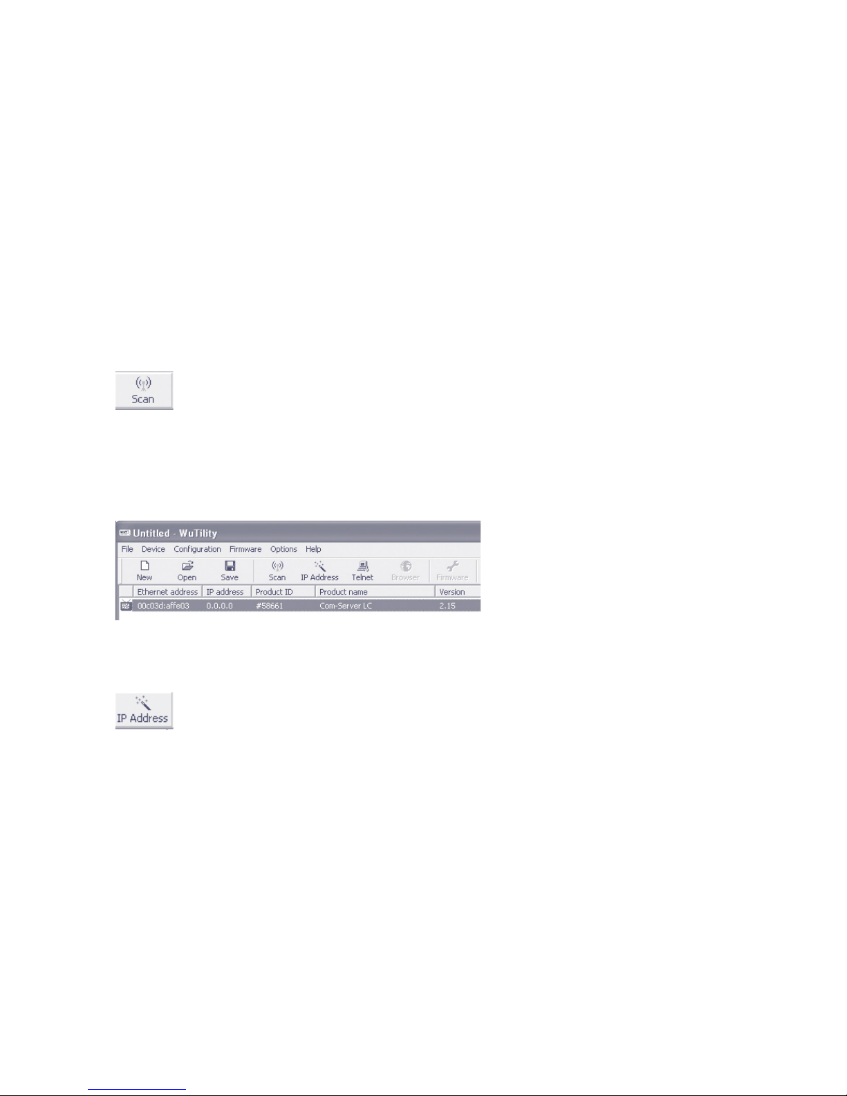
WuTility automatically searches the local network for connected W&T network devices and creates an inventory list. This
search process can be repeated manually as often as desired
by clicking on the Scan button:
Within the inventory list you can identify the desired device based on its MAC address. For initial installations its IP
address is 0.0.0.0.
Select the device and click on the IP address button:
18
W&T
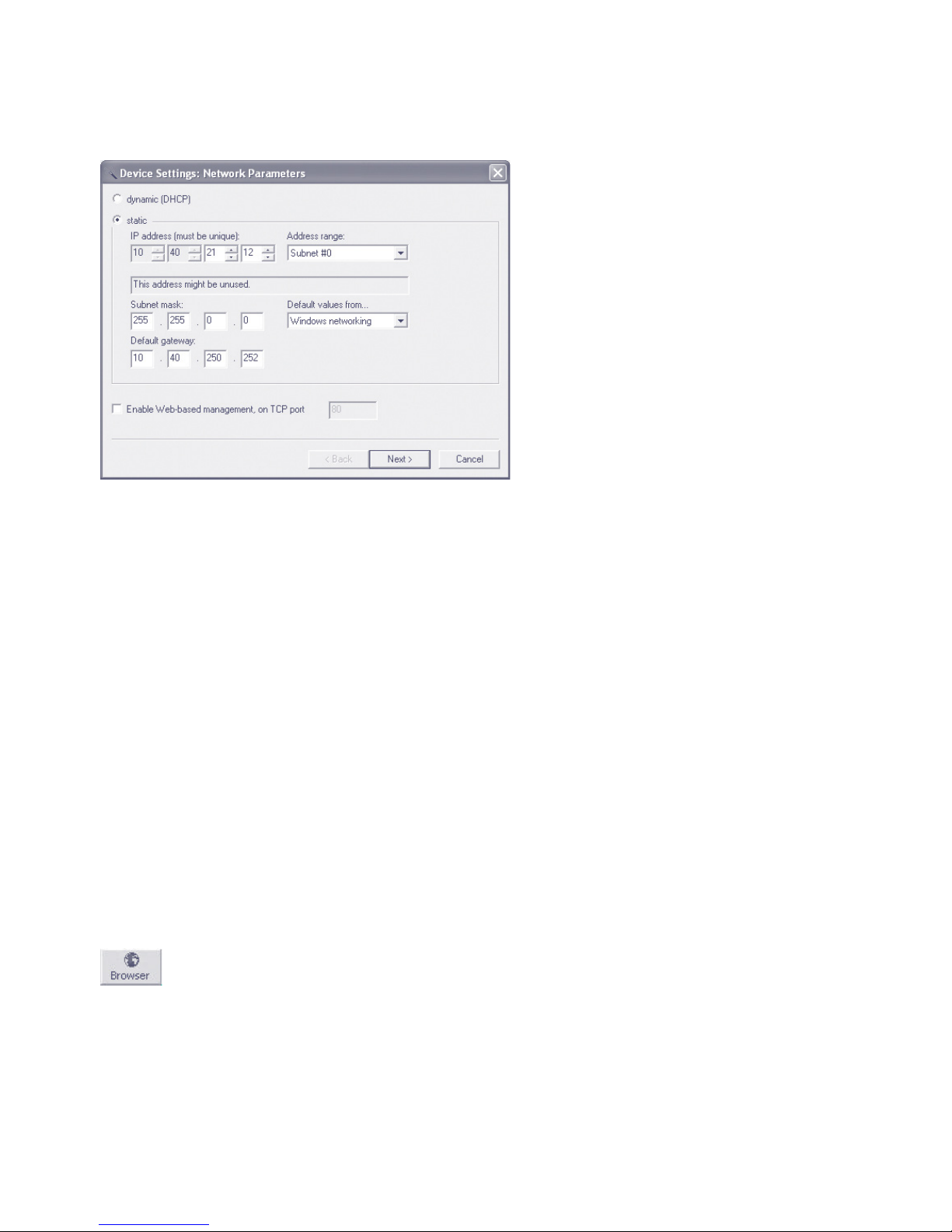
Step 2: Assign the IP parameters
The Static option allows you to assign fixed basic parameters
while simultaneously disabling the DHCP protocol in the device. Enter the desired values for IP address, subnet mask and
gateway address in the corresponding entry fields. The DHCP
option enables DHCP protocol in the device, and operation
with a static IP address is no longer possible (see IP Assign-
ment using DHCP Protocol for detailed information).
Clicking on the Next button assigns the network parameters
to the device. After acknowledging the resulting message, all
the columns in the WuTility device list are filled in with information.
If necessary, the remaining configuration of the device is done
using Web-Based-Management. Click on the Browser button.
Browser:
Additional information can be found in the section Configuration Accesses for the Web-Thermometer.

19
W&T
3.2 Assigning the IP using DHCP protocol
DHCP protocol is activated by the factory default settings, so
that in network environments dynamic IP assignment is sufficient for connecting the device to the network. The following
parameters can be assigned using DHCP:
• IP address
• Subnet mask
• Gateway address
• DNS-Server
3.2.1 Manual activation of DHCP
To prevent unintended address assignments or address changes, DHCP protocol is automatically deactivated when using
all other methods for assigning the IP parameters. The following methods are then available for later activation of DHCP.
• Management-Tool WuTility
Select the desired device from the device list and click on
the IP Address button. In the following dialog check the
option DHCP and then click on Next.
• WBM configuration
In the menu branch Basic settings r Network r TCP/IP
Settings you can activate DHCP protocol.
1
A set static IP address is deleted after DHCP is
activated and the associated automatic reset. The device
automatically sets this to 0.0.0.0 and starts sending DHCP
requests.

20
W&T
3.2.2 System name
To support any automatic updating of the DNS system by
the DHCP server, the device identifies itself within the DHCP
protocol with its system name. The factory default setting
for this is WEBIO- followed by the last three places of the
Ethernet address. For example the factory set system name of
a device with the Ethernet address 00:c0:3d:01:02:03 is WE-
BIO-010203. The system name of the device can be changed
in the configuration. For additional information refer to the
section Menu: Basic Settings r Language/Infos.
3.2.3 Lease time
The lease time determined and transmitted by the DHCP
server specifies the Time-To-Live of the assigned IP address.
After half the lease time has expired, the device attempts to
extend the time for the assigned DHCP server and up update
the address. If this is not possible by the time the lease time
expires, for example because the DHCP server can no longer
be reached, the device deletes the IP address and starts a new
cyclical search for alternate DHCP servers for the purpose of
assigning a new IP address.
Because of the absent clock, the lease time associated with
the current IP address is no longer available after a reset.
After the restart therefore a corresponding update request is
issued with the original DHCP server. If the latter is not resolvable at this point in time, the device deletes the IP address
and starts a new cyclical search for alternate DHCP servers.
If DHCP is activated, the remaining lease time together with
the current IP address is displayed in the menu item device
Information using the format hh:mm:ss.

21
W&T
3.3 Assigning the IP using the ARP command
Requirements
This method can only be used if the device does not already
have an IP address, i.e. the entry is 0.0.0.0. To change an
IP address, use one of the other methods described in this
section or use the configuration menu over web based management. If the device has any other value, this access is
disabled.
When the factory setting is in effect as well as after a manual
changeover from static to DHCP, the method for assigning
the IP described in this section functions only after a delay of
approx. 2 minutes after a reset or after power-up.
This method does not work across networks, e.g. through
routers. This means the PC and device used for assigning
must be connected to the same physical network segment.
Only IP addresses whose Net-ID is identical to that of the assigning computer can be assigned.
1
To avoid unintended changes to the IP address, the
DHCP client of the Com-Server is automatically deactivated when configuring using a static ARP entry.
Step 1
Read off the Ethernet address of the device from the sticker
on the side of the housing.
58xxx [Typ]
EN=00c03d004a05
OK xxxxxx
Ethernet address
Insert a static entry into the ARP table of the computer using
the following command line:
arp -s [IP address] [Etherenet address]

22
W&T
E.g. under Windows:
arp -s 172.16.231.10 00-C0-3D-00-12-FF
E.g under UNIX/Linux:
arp -s 172.16.231.10 00:C0:3D:00:12:FF
1
The IP addresses must be without leading zeros in
all Windows environments. Otherwise the entry is incorrectly interpreted by the system and an incorrect IP address
is assigned to the device. In Windows Vista and newer the
prompt cmd.exe necessary for invoking the ARP command
must be started using Administrator rights.
Step 2
Use the following command line to ping the device with the
desired IP address:
ping 10.40.21.12
The device takes the IP address of the first network packet
sent to it as its own and saves it in non-volatile memory. The
ping requests of the PC are then replied.
It is not possible to configure the subnet mask and gateway
address using a static ARP entry. These need to be set in a
separate Telnet configuration session (see section Basic Confi-
guration of the device).

23
W&T
3.4 Assigning the IP using the serial port
After a device reset a time window of around 1-2 seconds is
available, during which you can assign a new IP address, subnet mask and gateway address by entering at least 3 „x“.
In contrast to other methods described above, this serial
method functions regardless of whether the device already
has an IP address, a password or not. The procedure can be
repeated as often as desired.
1
To avoid unintended changes to the IP address, the
DHCP client of the device is automatically deactivated
when configuring using the serial port.
Preparations/requirements
First connect the serial port A of the device to a computer. For
a standard PC or laptop, you will need a crossed RS232 cable
where only the pins 2,3, and 5 are connected.
Any serial terminal program can be used for assigning. The
following transmission parameters must be set regardless of
any other settings in the device:
9600 baud, no parity, 8 data bits, 1 Stop bit, no Handshake
Start the serial configuration mode
Reset the device by interrupting the power. While the device
is starting up, use the terminal program to send the letter x
at least three times. The device will then return the prompt
IPno.+<Enter>:.
Assigning the IP settings
Use the usual format (xxx.xxx.xxx.xxx) to enter the IP
address, and end the entry by pressing <Enter>. If the entry was accepted, the acknowledgement is the assigned IP
address. Otherwise you will get a FAIL message followed by
the last current IP address.

24
W&T
Together with the IP address, the subnet mask and gateway
address can also be assigned serially. The entry is separated
by commas and follows the IP address. Entering as shown in
the following example will assign IP address 172.17.231.99,
subnet mask 255.255.255.0 and gateway 172.17.231.52 to
the device.
Exampel: Assigning the IP address:
IP no.+<ENTER>: <- Web-Thermometer
172.17.231.99 -> Web-Thermometer
Example: Assigning IP address, Subnet mask and gateway
IP no.+<ENTER>: <- Web-Thermometer
172.17.231.99, 255.255.255.0,172.17.231.1 -> Web-Thermometer
3 Spannungsversorgung

25
W&T
4 Supply voltage
The Web-Thermometer can also be operated either using PoE
or from an external power supply.
The current draw can be found in the technical appendix.
4.1 Power over Ethernet
In PoE environments (Power-over-Ethernet, IEEE802.3af) power
is provided by the network infrastructure. The device supports both phantom power using data pairs 1/2 and 3/6 as
well as power feed using the unused wire pairs 4/5 and 7/8.
The Web-Thermometer is a device in PoE Power Class 1 (power consumption 0.44 to 3.84W).
4.2 External supply
As an alternative to PoE power supply the device can also be
powered by an external power supply connected to the screw
terminals on the underside of the housing. A half-wave rectifier makes the input reverse polarity protected. AC or DC
power may be used, whereby the following limit values must
be observed:
• AC: 18Vrms (- 10%) - 30Vrms (+10%)
• DC: 12V (-10%) - 48V (+10%)
(before SN 2283238 24V (-10%) - 48V (+10%))
When powering with DC voltage polarity must be observed:
L+M
+12-48V DCGND

26
W&T
5 Ethernet interface
The Web-Thermometer incorporates an IEEE 802.3-compatible
network interface.
5.1 Link status
The Link status is indicated on the two LEDs built into the
RJ45 jack.
• Link/Activity (green)
ON indicates a valid link to a hub or switch port. The LED
flashes when there is data traffic.
• Speed (yellow)
ON indicates a 100MBit/s-link (100BaseT). OFF indicates
10MBit/s (10BaseT)
5.2 10/100BaseT on RJ45
The Web-Thermometer has a 10/100BaseT network interface
on a shielded RJ45 connector. The pin assignments shown
below correspond to an MDI interface, so that the connection
to the hub or switch is made using a max. 100m long 1:1
shielded patch cable.
Speed Link/
Activity
1 2 3 4 5 6 7 8
The network connection is galvanically isolated with respect
to the supply voltage as well as the serial interface(s) for at
least 1,5kV
rms
.
Auto Negotiation: 10/100BaseT, Full/Half Duplex
The device is factory set to operate in Auto-Negotiation mode
on the network side. The data transmission speed and duplex
are automatically negotiated with the connected switch/hub
and set accordingly.

27
W&T
6 Connecting the sensor
6.1 NTC sensor measuring input (#57714)
The cable of the sensor is not extendable. Please, use exclusively the added sensor.
6.2 Pt100/1000 sensor measuring input (#57715)
Die Zuleitung des Messsensors kann nahezu beliebig verlängert werden. Sofern eine Verlängerung gewünscht ist, wird
empfohlen möglichst gut geschirmte Leitungen zu verwenden
um Störeinflüssen vorzubeugen. Wenn Sie einen alternativen
PT100/PT1000-Messfühler anschließen möchten, oder die Zuleitung verlängern möchten, ist die Steckerbelegung wie folgt:
6.3 Combined sensor measuring input (#57713, #57720)
The provided sensor uses a digital measuring value transfer.
A lengthening is possible up to a total length of 20 m (2 m of
sensor cable + 18 m of lengthening).
We recommend a DB9 plug connector for a connection to the
provided sensor for the lengthening.
we recommend the use of a data cable with the least specification Cat. 5 (shielded) or better and the following pin
allocation:

28
W&T
29
W&T
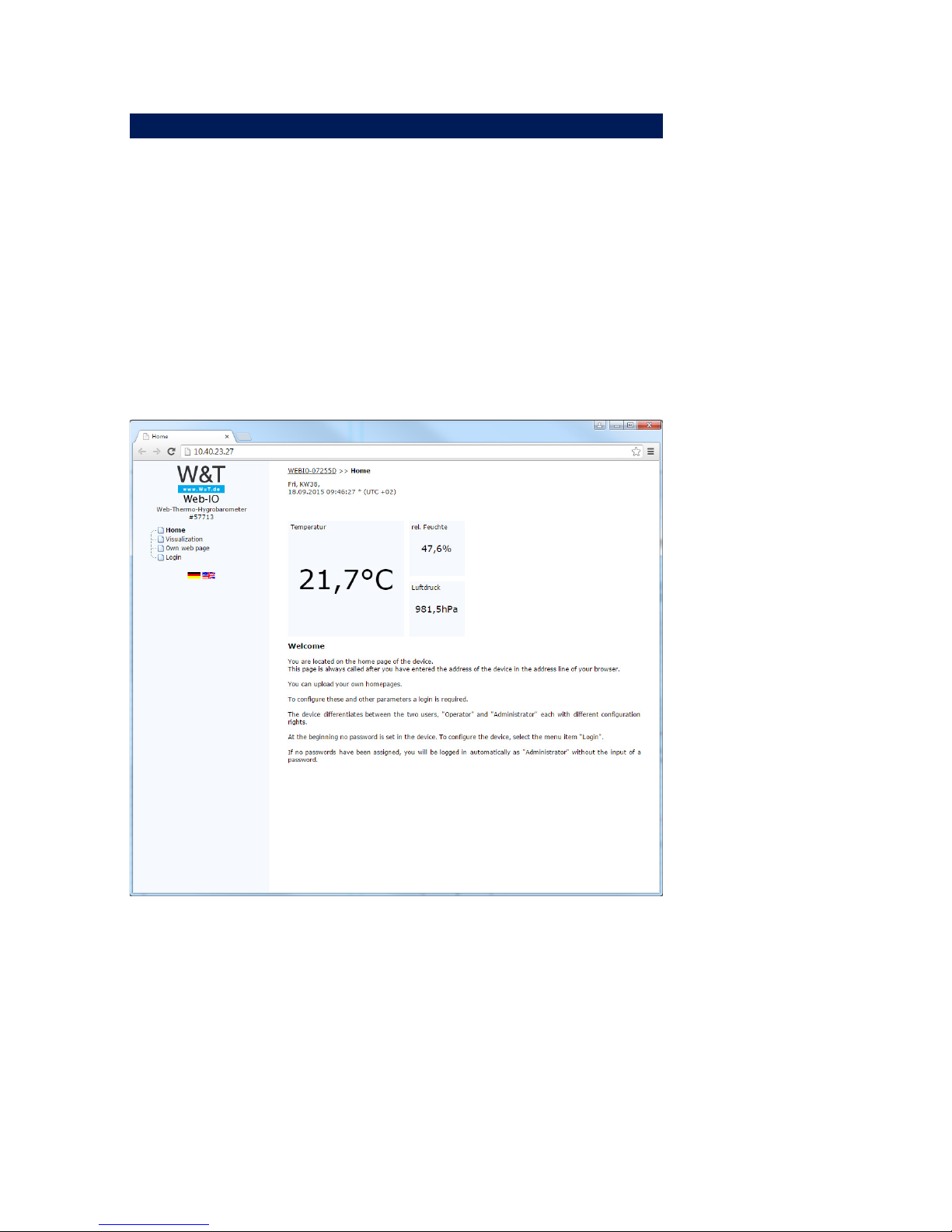
7 Configuration Using Web-Based Management
The remaining configuration is done using the web page of
the device. To open this, enter the assigned IP address in the
address line of your web browser:
http://<IP-adresse>
7.1 Home
The following pages are also available:

30
W&T
7.2 Visualization
This page shows you a graphical display of the stored measurement values.
The displayed control elements enable you to adapt this display temporarily, as long as you are on this page. A non-temporary change can be made from the configuration menu (s.
Communication paths >> Web pages).

31
W&T
7.3 Own webpage
This page can be individually adjusted or replaced and serves
as an example. Here you are also able to take a look at the
data logger of the device.
7.4 Login

32
W&T
The Login dialog gives you access to the device configuration. The device differentiates between an administrator and a
standard user with different access rights.
As shipped the device has no password configured. Select the
administrator or user and click on “Login“.
The menu tree with all the configuration parameters is now
shown.
To get additional information about the respective configuration parameter, click on the Info button on the right border of
the corresponding parameter.

33
W&T
8 Basic Settings
This configuration area is where you make all the settings
needed for the various operating modes.
8.1 Network
Here is where you set the network basic parameters. You can
choose between automatic address assignment per DHCP or
manual configuration of the parameters. If you wish to configure communication parameters with names instead of IP
addresses in the further configuration, you can configure additional DNS servers here in addition to any DNS server which
is assigned via DHCP.

34
W&T
8.2 Sensors
Here among other things you are able to configure the labels
for the sensors and, for temperature sensors, the units.
If you want to make an adjustment to the sensors, you can
choose between 1-point compensation, whereby a correction
value is added to or subtracted from the measurement value,
or 2-point compensation, in which a straight line is calculated
over the measuring range
8.3 Date/Time
The device time is necessary for obtaining plausible time
stamps for storing the measurement values.
Enter the time manually or use the convenience of the automatic time-of-day compensation using a time server.
Here you can also enable or disable the use of daylight savings time.
8.4 Language/Infos
Here you configure the standard language of the device.
This is automatically used when device pages are opened.
The standard language can be dynamically switched during
operation using the flags below the configuration menu. This
switch is temporary and not saved.
On this page you can change information and device labels
and upload an individual logo, which is displayed above the
configuration menu.

35
W&T
8.5 Data storage
Configure at what time interval the measurement data should
be saved in the internal data logger and which sensors should
be included.
!
A change to these settings will clear the entire data
logger and the measurement recording will begin over
again.
In addition, you can download the contents of the data logger
as a CSV file for further processing. On this page you can also
clear the data logger.
8.6 Password
Set up optional password protection for access to the configuration.
You can set a password for an administrator-user and for an
operator-user.
The operator-user has no access rights to system settings for
the device, such as changing network parameters etc.
!
If you assign an administrator password, it must be
stored for IP address changes via WuTility or firmware
updates.

36
W&T
9 Communication paths
This device can communicate over various network protocols
and services. Here you configure all the parameters necessary
for this.
9.1 Web pages
This device has three preset pages which can be selected as
the start page.
The default homepage shows you the current values of the
individual sensors, which are updated cyclically.
The visualization page makes it possible to represent the
measurement values graphically.
The user page can be individually designed. To do this it can

37
W&T
be downloaded from the device, edited by you and again
uploaded.
To display the measurement values on the user.htm page you
can use the following tags in the source text, which are replaced with the corresponding values when the page is opened:
<w&t_tags=t1>
Shows the current temperature (°C) of the first temperature
sensor. When multiple sensors are used this index is numbered in sequence.
<w&t_tags=h1>
Shows the current relative humidity (%) for models 57713 and
57720.
<w&t_tags=ah>
Shows the current absolute humidity (g/m³) for models 57713
and 57720.
<w&t_tags=pa>
Shows the absolute air pressure (hPa) for model 57713.
<w&t_tags=pNN>
Shows the calculated air pressure (hPa) above sea level for
model 57713 (meteorlogical value).
<w&t_tags=al>
Shows the set altitude of the location of the device for model
57713. (m)
<w&t_tags=time>
Inserts the current time of day.
Background color:
For values shown in tables you use use corresponding background colors depending on the sensor state:
<w&t_tag=bct>
Describes a background color (BGColor), which depends on
the alarm status of the temperature sensor. If a limit has been

38
W&T
violated, this color is red. Otherwise the tag does not describe
any explicit color. This tag is necessary for example for showing limit violations in red in the log table. (°C)
<w&t_tag=bch>
Background color for the relative humidity value
<w&t_tag=bcah>
Background color for the absolute humidity value
<w&t_tag=bcrc>
Background color for the current rate of change
<w&t_tags=sensorx>
Inserts the name of sensor x in the page.
<w&t_tags=device_name>
Inserts the assigned device name.
<w&t_tags=device_text>
Inserts the freely configurable, descriptive text for the device.
<w&t_tags=location>
<w&t_tags=contact>
Inserts the respective text blocks which can be configured
under Language/Infos.
This page also provides all the parameters needed for adjusting the visualization.

39
W&T
9.2 Mail
The e-mail function allows you to send messages to one or
more e-mail recipients. Here you configure the access parameters for your mail server.
9.3 Cloud
The W&T cloud service is a complete solution which not only
allows long-term documentation of measurement data in the
internal data logger but also makes it possible to save the
data in online storage.
Measurement data are passed directly from the measurement
point to the cloud, where they are then available online.
A user account is required for the W&T cloud. This can be created on the web pages at:
http://cloud.wut.de
9.4 RSS
The device provides an RSS feed which can be subscribed to
by feed readers. Here you configure the necessary channel
settings.
9.5 SNMP/Syslog
Here is where you make the SNMP and syslog basic settings.
The device can be incorporated into your existing automation
system via SNMP or syslog.
Retrieve device and sensor data using corresponding OIDs or
send messages via SNMP trap or syslog.
An MIB is available for direct downloading at

40
W&T
http://<ip-address>/mib.zip
9.6 FTP
Measurement data can be stored directly on an FTP server for
archiving and checking. Here you configure the basic settings
for the FTP server.
9.7 Socket access
You can obtain measurement data directly from the device
using a socket access.
In the simplest case you send the command “GET/Single” to
the device to retrieve all the measurement data from the device.
Here you configure the setting for access via HTTP and UDP.

41
W&T
10 Alarms/Messages
Messages for limit violations are received as soon as they
occur via e-mail or SNMP trap. Here you select the desired
trigger and configure the desired messaging type. You can
configure up to 12 different messages.
Clicking on the button a new message. Enter
the desired parameters and select the type of messages. After
creating the message using the button
,moni-
toring of the triggering condition is immediately active.
You can find the created message both in the configuration
menu and on the overview page for messages. Here you
are also able to test messages by clicking on the button
. To rescind the trigger condition for the test,
click on
.
The button
deletes the message. This change
becomes effective immediately after a security prompt.

42
W&T
To incorporate measurement values into the message texts
the following tags are used which are replaced within the text
by the available values.
Function
comma s
p
elling (##,#) dot spelling (##.#)
<T1> <t1>
Temperature: Displays the
current tem
p
erature.
<H1> <h1>
Humidity: Displays the current
relative humidit
y.
<AH> <ah>
Absolute humidity: Displays
the current absolute humidity.
<RC> <rc>
Rate of change: Displays the
rate of change from the last 5
minutes.
<PA> <pa>
Absolute air pressure: Displays
the current absolute air
p
ressure.
<PN> <pn>
Sea-Level air pressure:
Displays the air pressure
counted back to Mean Sea
Level.
<V> <v>
VOC: Displays the current air
quality value. (#57618)
<O1> <o1>
Output: Shows the current
output state (ON, OFF)
(#57616
)
Alarm active: Shows all alarms
(numbers, komma separatet)
which are currently active.
Alarm sensor number:Shows
all sensors (numbers, komma
separated) which match with
the configured alarm values
per alarm.
Alarm sensor name: see above,
but with sensor names (komma
separated)
Device Name: S hows the
device name.
Displays the actual time and
date as a string.
Year (####): Displays the year.
Month (##): Displays the
month.
Day (##): Displays the day.
Hour (##): Displays the hour.
Minute (##): Displays the
minute.
Second (##): Displays the
second.
W&T tag value
W&T tag date + time
<AA>
<AN>
<AS>
<DN>
<$i>
<$s>
<Z>
<$y>
<$m>
<$d>
<$h>

43
W&T
11 Diagnosis
Here you will find all the runtime errors which the device has
generated.
Errors which have occurred but which are no longer current
can be found in the diagnostics archive.
Errors occurring while entering parameters do not appear on
this page, but rather are displayed directly on the parameter.
44
W&T
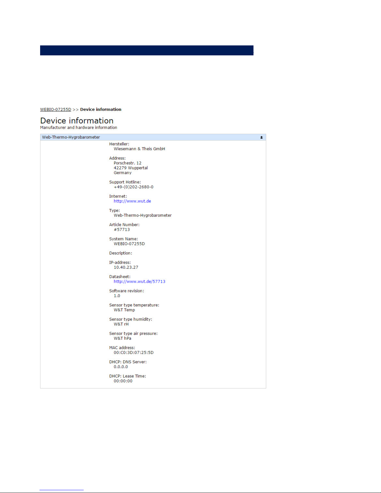
12 Device information
Here you find descriptive information about your device and
manufacturer’s descriptions. The contents of this information
can be changed in the basic settings under Language/Infos.

45
W&T
13 Maintenance
13.1 LED Test
After clicking on this button both the internal LEDs of the device come on for 2 seconds. This serves to identify the device.
13.2 Reboot
Restarts the device and resets all network connections.
13.3 Factory defaults
The device is reset to the factory default settings. All configuration parameters and passwords are cleared. After a reset
you must start over with IP address assignment.

46
W&T
13.4 Save configuration
Clicking on the Download button downloads a file containing
the entire device configuration. This can be edited in a text
editor.
13.5 Restore configuration
Select a configuration file and upload it to the device. After
a restart all the configuration parameters are applied by the
device

47
W&T
14 Individual request of measurement values
14.1 Request via TCP/IP
It is possible to manually request the current measurement
values in CSV format (comma-separated data) through a sokket connection. This function is used for requesting individual
data without using the web interface.
To do this, send the following string to Port 80:
GET /Thermo.csv
This expression can also include additional parameters which
determine the contents:
start=ttmmjjjjThhmmss
Start-date and –time for the measurement data to be loaded
end=ttmmjjjjThhmmss
End-date and –time for the measurement data to be loaded
DTb=x&
Output interval, where x =
1 -> 15 Sek.
2 -> 30 Sek.
3 -> 1 Min.
4 -> 5 Min.
5 -> 15 Min.
6 -> 60 Min.
The expression must begin with “?” after the file name, where
the individual variables are separated by a “&”.

48
W&T
Example:
http://<ip-adresse>/thermo.csv?start=01012010T123000&end=30032010T200000&DTb=3&
The above expression generates a CSV file which contains
the measurement data from 01.01.2010, 12:30 p.m. until
03.30.2010, 8:00 p.m. in 1 minute intervals.
To request the individual current measurement value, send:
GET /Single1
for the 1st measuring channel
GET /Single2
for the 2nd measuring channel, etc.
To receive an output for all measuring channels, send:
GET /Single
without Index.
14.2 Requesting via UDP
Open a UDP connection to the IP address of the device or
to the Net-ID as a broadcast and Port 42279 (preset can be
changed).
Then send one of the above GET /Single expressions to the
device and the device will return the measurement values on
the port you are using.
i
When using multiple devices it may make sense to also
have the name and IP address of the device included
with broadcast messages. To do this, select “Enable GET
Header” under “Communication paths >> Socket access”.

49
W&T
14.3 Requesting via SNMP
The sensors can be queried directly using SNMP instructions.
The paths of the different model variations are:
#57713 Web-Thermo-Hygrobarometer:
1.3.6.1.4.1.5040.1.2.37....
#57714Web-Thermometer NTC:
1.3.6.1.4.1.5040.1.2.38....
#57715 Web-Thermometer Pt100/Pt1000:
1.3.6.1.4.1.5040.1.2.39....
#57716 Web-Thermometer Relay:
1.3.6.1.4.1.5040.1.2.40....
#57718 Web-Thermometer Air Quality:
1.3.6.1.4.1.5040.1.2.41....
#57720 Web-Thermo-Hygrometer
1.3.6.1.4.1.5040.1.2.42....
Access the sensors through the following path:
<IP-Adresse> 1.3.6.1.4.1.5040.1.2.X.1.3.1.1.1 = First channel
with a decimal point with comma separation
<IP-Adresse> 1.3.6.1.4.1.5040.1.2.X.1.4.1.1.1 = First channel
as three place integer value, without comma separation
<IP-Adresse> 1.3.6.1.4.1.5040.1.2.X.1.8.1.1.1 = First channel
with one decimal place with decimal point separation

50
W&T
The last index describes the channel number you are
querying.
!
For querying indicate the configured SNMP read or read/
write community.
An MIB for incorporating into management applications is
available for downloading on the datasheet page of the device
on the W&T homepage http://www.wut.de or in the device
itself at http://<ip-address>/mib.zip.
If you wish to change device settings via SNMP (IP address,
subnet mask, etc.) you must first start a session on the device
using your SNMP manager.
Entering the administrator password in the variable
wtWebGraphThermoBaroSessCntrlPassword
opens a session. By reading the variable
wtWebGraphThermoBaroSessCntrlConfigMode
you can check whether the session was successfully opened.
1 = Session opened, device is in configuration mode.
0 = Opening of the session failed. Check whether an incor-
rect password was entered.
After successfully opening the session, you can make any
desired configuration changes using the variables defined in
the private MIB.
After configuration is finished, close the session by writing
the variables
wtWebGraphThermoBaroSessCntrlLogout
wtWebGraphThermoBaroSessCntrlLogout =

51
W&T
1 All changes are saved
2 Quit without saving
If while a session is open no SNMP communication takes place
for a period of 5 minutes, the device itself will close the session and all changes are discarded.
1
Opening an SNMP session has priority over an HTTP
login. This means: A user with operator or administrator rights loses his browser access as soon as an
SNMP session is opened.
The description of the individual SNMP variables, OIDs etc.
can be found in the private MIB.

52
W&T
15 Firmware Update
The operating software for the Web-Thermometer is being
continuously improved. The following section describes the
procedure for uploading new firmware.
. Where is the latest firmware available?
. Firmware update under Windows
15.1 Where is the latest firmware available?
The most current firmware including the available update
tools and a revision list are published on our website at the
following address: http://www.wut.de
Please first write down the 5-digit model number located on
the Web-Thermometer before downloading. From the homepage you can then reach the product overview sorted by
article numbers, which takes you directly to the datasheet for
the device. Here you follow the link to the current version of
the firmware.
15.2 Firmware update over the network under Windows
Prerequisite is a PC running Windows XP/Vista/7/8/8.1/10
with a network connection and activated TCP/IP stack. The
update process requires two files which are as noted above
are available for downloading on the homepage at http://
www.wut.de:
· The executable WuTility tool for sending the firmware to the
Web-Thermometer
· The file with the new firmware for sending to the device.
No special preparation of the Web-Thermometer is necessary
for the firmware update.

53
W&T
The WuTility tool used for the update detects all WuT devices
located in your network and is for the most part self-explanatory. If any questions arise, please use the associated documentation or go to online help.
!
Do not intentionally interrupt the update process by disconnecting power or pressing the Reset button if one is
present. The Web-Thermometer will be inoperable after
an incomplete update
Never mix files with different version numbers in file names.
This will cause the device to become inoperable.
The Web-Thermometer automatically detects when the transfer of the new operating software is complete and then performs an automatic reset.

54
W&T
16 Hardware-Reset to factory defaults
A reset of the device to its factory defaults can be done via
hardware. For this purpose the device has a jumper on the
board. For normal operation this jumper must be out. To set
the factory defaults, proceed as follows:
• Power off the device and open the enclosure
• Close the jumper and reconnect the supply voltage. An
internal self-test will be performed during which messages
will be issued on serial port. The Fail messages in the lines
Port A: and TP Test: can be ignored.
• The self-test will be finished in approx. 20s, at which point
the factory defaults are active.
• Turn off the device, open the jumper and close up the
housing again.
1
Resetting the non-volatile memory results in a loss
of all the settings which are different from the factory
defaults, including the IP address, passwords and all measured values.

55
W&T
17 Technical data
17.1 Technical data for the articles 57714 and 57715
Prod. No. 57714, 57715
Network: 10/100BaseT autosensin
g
Supply voltage:
Power-over-Ethernet or
12-48V DC (+/-10%) or
18Veff-30Veff AC (+/-10%) via screw
terminal
Measuring unit (57714)
Sensor: NTC 10k
Measuring range: -45°C...75°C
Resolution: 1/10°C
Measuring error: ±0,3°C, ±5,1%
Storage frequency: 15, 30 sec, 1, 5, 15, 60 min
Memory depth (4MB): min. 16 weeks, max. 20 years
Deviation of the internal clock: max. 1 min. / Month
M
easuring unit (57715)
Sensor: Pt100, Pt1000 connection, 2-, 3- or 4-conductor
Measuring range:
W&T sensor: -50°C...180°C
PT100/PT1000 measuring input: -200°C...650°C
Resolution: 1/10°C
Measuring error: ±0,3°C, ±0,2%
Storage frequency: 15, 30 sec, 1, 5, 15, 60 min
Memory depth (4MB): min. 16 weeks, max. 20 years
Deviation of the internal clock: max. 1 min. / Month
Power supply
typ. 62mA @24VDC, 80mA @20VAC,
max. 70mA @24VDC, 40mA @48VDC
PoE Class 1 (0,44 - 3,84W
)
Emergency access: serial port RS232, 9600 baud, 8 data bits, 1 stopbit,
no
p
arity
Housin
g
: Compact plastic housing, 105 x 75 x 22mm (lxwxh)
Wei
g
ht: approx. 200
g
Ambient storage temperature: -40..+70°C
Ambient operating temperature: non-row mounting:
0 .. +60°C
row mountin
g
:
0 ..+50°C
Current consumption:

56
W&T
17.2 Technical data for the articles 57713 and 57720
Prod. No. 57713, 57720
Thermo-Hygro Probe: I2C connection
Air
p
ressure probe: SPI connection (57713 only)
Network: 10/100BaseT autosensin
g
Supply voltage:
Power-over-Ethernet or
12-48V DC (+/-10%) or
18Veff-30Veff AC (+/-10%) via screw
terminal
M
easuring unit
Measuring range: -40°C...85°C, 0..100% rF, 10-1100 hPa (57713 only)
Resolution: 1/10 °C, 1/10% rF, 0.1 hPa
Measurin
g
error: Temperature:
t
yp
. @ 25°C ±0.3°C
max. @ -40..85°C ±1.5°C
Relative humidity:
t
yp
. @ -20..60°C (normal range) ±1.8%rH (10-90%rH)
max. @ -20..60°C (normal ran
g
e) ±4%rH (0-100%rH)
temporary @ -40..85°C (max range) +3%rH after 60h
O
p
eration outside normal range
Lon
g
-term stability typ. <0.5%rH / year
Atmos
p
heric pressure (57713 only):
t
yp
. @ 25°C ±0.8hPa (750..1100hPa)
max. @ 25°C ±2.5hPa (750..1100hPa)
max. @ -40..85°C: ±3.5hPa (300..1100hPa)
Lon
g
-term stability: typ. -1hPa / year
Stora
g
e frequency: 15, 30 sec, 1, 5, 15, 60 min
Memory depth (4MB): min. 7 weeks, max. 20 years (57713)
min. 12 weeks
,
max. 20 years (57720
)
Deviation of the internal clock: max. 1 min. / Month
Power suppl
y
typ. 62mA @24VDC, 80mA @20VAC,
max. 70mA @24VDC, 40mA @48VDC
PoE Class 1 (0,44 - 3,84W)
Emergency access: serial port RS232, 9600 baud, 8 data bits, 1 stopbit,
no parity
Housin
g
: Compact plastic housing, 105 x 75 x 22mm (lxwxh)
Wei
g
ht: approx. 200
g
Ambient storage temperature: -40..+70°C
Ambient operating temperature: non-row mounting:
0 .. +60°C
row mountin
g
:
0 ..+50°C
Current consumption:

57
W&T
17.3 Technical data for the article 57716
Prod. No.
57716
Thermo-Probe:
Pt100/Pt1000-Connection via screw terminal
Network: 10/100BaseT autosensin
g
Supply voltage:
Power-over-Ethernet or
12-48V DC (+/-10%) or
18Veff-30Veff AC (+/-10%) via screw
terminal
M
easurin
g
unit
Sensor: Pt100/Pt1000-Connection, 2-,3- or 4-wire
W&T Sensor: -50°C...180°C
PT100/PT1000-In
p
ut: -200°C...650°
C
Resolution:
1/10°C
Measurin
g
error:
Measurin
g
unit:
±0,3°C, ±0,2
%
PT100/1000 Sensor Class A:
±0,15°C, ±0,2
%
Storage frequency:
15, 30 sek, 1, 5, 15, 60 min
Memory depth (4MB): min. 16 weeks, max. 20
y
ears
Deviation of the internal clock: max. 1 min. / month
Semiconductor-Relaiy-Output
Digital output: 1
p
otential-free semiconductor-rela
y
max. switching current: typ. 300mA AC/DC (peak 500mA)
max. switching voltage: 39V AC/DV
max. power consumption: 11,7W AC/DC
Power supply
typ. 62mA @24VDC, 80mA @20VAC,
max. 70mA @24VDC, 40mA @48VDC
PoE Class 1 (0,44 - 3,84W)
Housin
g
: Plastic compact housing, 105x75x22mm
Wei
g
ht: approx. 200
g
Ambient storage temperature: -40..+70°C
Ambient operating temperature: non-row mounting:
0 .. +60°C
row mounting:
0.. +50°C
Measuring range:
Current consumption:

58
W&T
17.4 Technical data for the article 57718
Prod. No.57718
Thermo-H
yg
ro Probe:
I2C connection
VOC probe:
I2C connection
Network:
10/100BaseT autosensin
g
Supply voltage:
Power-over-Ethernet or
12-48V DC (+/-10%) or
18Veff-30Veff AC (+/-10%) via screw
terminal
Measurin
g
unit
Measuring range:
0°C...50°C, 5..95% rF, 450-2000ppm VOC/CO2Equivalent
Resolution: 1/10 °C, 1/10% rH
VOC sensor, detected substances: Alcohols
Aldehydes
aliphatic hydrocarbons
Amines
Aromatic hydrocarbons
CO, CH4, LPG
Ketones
Or
g
anic acids
Measuring error:
Temperature:
typ. @ 25°C ±0.3°C
max. @ 0..50°C ±1.2°
C
Relative humidity:
typ. @ 25°C ±3%rH
max. @ 0..50°C ±7%rH (0-100%rH
)
Long-term stability typ. <0.5%rH / year
Stora
g
e frequency:
15, 30 sek, 1, 5, 15, 60 min
Memory depth (4MB):
min. 7 weeks, max. 20 years
Deviation of the internal clock: max. 1 min. / month
Power su
pply
typ. 62mA @24VDC, 80mA @20VAC,
max. 70mA @24VDC, 40mA @48VDC
PoE Class 1 (0,44 - 3,84W)
Housin
g
:
Plastic compact housin
g
, 105x75x22mm
Wei
g
ht:
approx. 200
g
Ambient storage temperature:
-25+50°C
Ambient operating temperature: non-row mounting:
0 .. +60°C
row mountin
g
:
0 ..+50°C
Current consumption:

59
W&T
18 Disposal
This device contains a non-rechargeable lithium button battery type BR (lithium carbon monofluoride) for retaining the
time even when the device is turned off. This battery must
be disposed of after its useful life has expired. Take it to an
official collection site for recycling.
First disconnect all cables from the device and open the device.
The button battery is located on the circuit board. Remove it
from its holder and take it to a recycler.
 Loading...