


Manual
Web-IO Analog-In/Out PoE
W&T
Type 10/100BaseT, 12-24V
Model 57661, 57662
Release 1.63, Jun 2010

W&T
© 06/2010 by Wiesemann & Theis GmbH
Microsoft, MS-DOS, Windows, Winsock und Visual Basic
are registered trademarks of Microsoft Corporation
Subject to errors and modifications:
Since errors are always possible, none of this information should
be used without checking. Please let us know of any mistakes or
unclear descriptions so that we can become aware of them and
correct them as quickly as possible.
Perform work on and with W&T products only as described here
and after you have read and fully understood the manual. Improper
use may result in hazardous conditions. We are not liable for
improper use. If in doubt, please check first with us or with your
dealer!

W&T
Introduction
The W&T Web-IO Analog-In/Out models include all the
functions in a single box for capturing your analog
measurements (0..20mA or 0..10V), tunneling them through the
network, saving and displaying them. A variety of alarm
functions are also available which can be custom added to your
own applications or into existing systems.
This manual contains all the information you need for
installation, configuration and operation of the Web-IO AnalogIn/Out devices..

W&T
Content
Introduction ............................................................................................ 3
1 Quick-start, Commissioning ......................................................... 7
1.1.1 Connect to power ................................................... 7
1.1.2 PoE supply ............................................................. 8
1.2.1 Wiring the in- and outputs .......................................9
1.3 Network connection ...................................................... 12
1.4 Assigning the IP address using „WuTility“ ....................... 13
1.5Assigning the IP address using DHCP protocol ................15
1.5.1 Enabling/Disabling DHCP ...................................... 15
1.5.2 System Name ........................................................ 16
1.5.3 Lease-Time ........................................................... 17
1.5.4 Reserved IP addresses ........................................... 18
1.5.5 Dynamic IP addresses ............................................ 18
1.6 Start page ..................................................................... 19
1.7 Assigning the basic network parameters ......................... 21
2 Graphical Representation of the Measurements ..................24
2.1 Basic functions ............................................................. 24
2.2 Config-Menu ................................................................ 26
2.3 Table ............................................................................28
3 Other Basic Settings ....................................................................... 29
3.1 Configuring the port and device name ............................ 29
3.2 Specifying Output Mode ................................................ 32
3.3 Compensation of the output controller (57662 only) ....... 33
3.4 HTTP - Controlling outputs in the browser ...................... 36
3.5 HTTP - Controlling outputs using a command string ....... 37
3.6 HTTP - Polling inputs using a command string ................ 38
3.7 BINARY - Socket programs with binary structures ............ 39
3.7.1 Specifying the operating mode ...............................40
3.7.2 The Web-IO Analog-In/Out as Socket-Server ............ 41
3.7.3 The Web-IO as Socket-Client .................................. 45
3.7.4 The Web-IO as UDP-Peer ........................................ 48
3.7.5 Password protection ..............................................51
3.7.6 BINARY - The IO structures .................................... 53
3.7.7 Definition of the IO structures ................................ 54
3.7.8 Working with the IO structures ............................... 56

W&T
3.8Box-to-Box ................................................................... 60
3.8.1 Configuring the Slave Web-IO ................................ 60
3.8.2 Configuring the Master .......................................... 63
3.8.3 Determining Box-to-Box connection status ............. 67
3.8.4 Quitting Box-to-Box mode ..................................... 68
3.8.5 Quitting Box-to-Box mode only for the Slave Web-IO 69
3.9OPC - Standardized access ............................................. 71
3.9.1 Installing the OPC-Server ....................................... 71
3.9.2 Uninstalling .......................................................... 72
3.9.3 Configuring .......................................................... 72
3.9.4 Configuring the Web-IO as an OPC device ............... 76
3.9.5 Program options ................................................... 79
3.9.6 Data model for OPC Data Access ............................ 81
3.9.7 OPC variables for Web-IO Analog ........................... 82
3.9.8 OPC Alarms & Events ............................................ 83
3.10 Local time setting ........................................................ 85
3.10.2 Summertime ............................................................. 86
3.11 Automatic time setting using a network time service ...... 88
3.12 Configuring the data logger ......................................... 89
3.13 Configuring the graphics output .................................. 91
3.13.1 Basic Settings ..................................................... 91
3.13.2 Select Sensor ...................................................... 94
3.13.3 Scale Config ....................................................... 95
3.14 Calibration ..................................................................97
3.15 Browser access ........................................................... 98
3.16 Sending alarms via e-mail ............................................ 99
3.17 SNMP incl. alarm sending per Trap .............................. 108
3.18 Sending alarms per TCP (Client Mode) ........................ 112
3.19 Sending alarms per FTP (Client Mode) ......................... 113
3.20 Syslog messages incl. alarm sending .......................... 117
3.21 Time-based report ..................................................... 120
3.22 Check Alarm ............................................................. 120
3.23 ASCII command strings per TCP Port 80 ...................... 121
3.24 ASCII command strings per UDP ................................. 122
3.25 UP-/Download ........................................................... 123
Subject to errors and modifications
5

W&T
4 Individual Measurement Polling ............................................ 125
4.1 Polling via TCP/IP ........................................................ 125
4.2 Polling via UDP ............................................................ 125
4.3 Polling via SNMP .......................................................... 126
5 Including Measurements in your own Web Page ............. 129
6 Data Logger .................................................................................... 134
7 Appendix ......................................................................................... 135
7.1 Alternative IP address assigning ................................... 135
7.2 Example for creating your own Web pages .................... 138
7.3 Firmware update ......................................................... 145
7.3.1 Where is the current firmware available? ................ 145
7.3.2 Firmware update over the network under Windows . 145
7.3.3 LED indicators .................................................... 147
7.4 Emergency access ....................................................... 149
7.5 Technical data ............................................................ 150
7.6 Disposal ..................................................................... 151
W&T
1 Quick-start, Commissioning
To start up the W&T Web-IO Analog-In/Out and make it visible
in your network only a few steps are necessary.
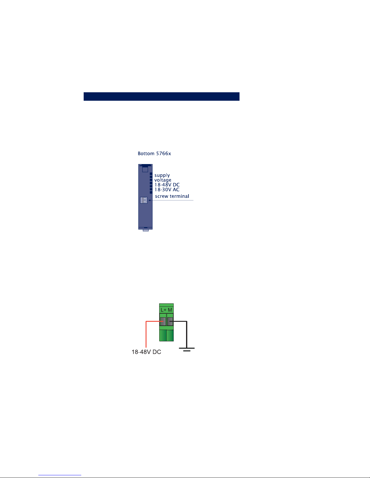
1.1.1 Connect to power
If you want to use a power supply, connect 18-48V DC or 1830V AC to the screw terminal provided. Polarity is uncritical
when connecting AC power supplies. When connecting DC power supplies please note the polarity as indicated on the screw
terminal adapter:
Subject to errors and modifications
7

W&T
To use the W&T model 11020 power supply, screw the power
supply plug into the screw terminal adapter:
1.1.2 PoE supply
The Web-IO Analog-In/Out can be used in PoE (Power-overEthernet) environments in accordance with IEEE802.3af. The
supply voltage is provided then by the network infrastructure
through the RJ45 terminal. The device supports both phantom
power using data pairs 1/2 and 3/6 as well as power on the unused
wire pairs 4/5 and 7/8.
To enable power management for the supplying components, the
W&T Web-IO Analog-In/Out is identified as a Power Class 1 device
with a power consumption of 0.44 to 3.8W.
As an alternative to PoE the device can also be powered externally
using the screw terminal located on the underside of the device.
Use of the W&T Web-IO Analog-In/Out is also possible in
networks wihtout PoE. In this casde simply use an external
!
power supply with the screw terminals as described above.
No additional configurations or settings are necessary.
8
W&T
1.2.1 Wiring the in- and outputs
Depending on the configuration the W&T Web-IO Analog-In/Out
can be wired as follows, whereby Ports 1 and 2 are indicated by
an „X“. The configuration is identical for both ports:
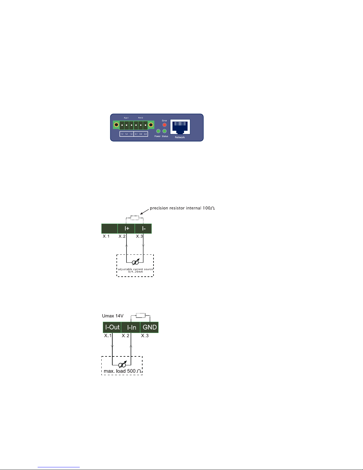
1.2.2 Current input 0..20mA, passive (#57661)
1.2.3 Current input 0..20mA, active (#57661)
Subject to errors and modifications
9
W&T
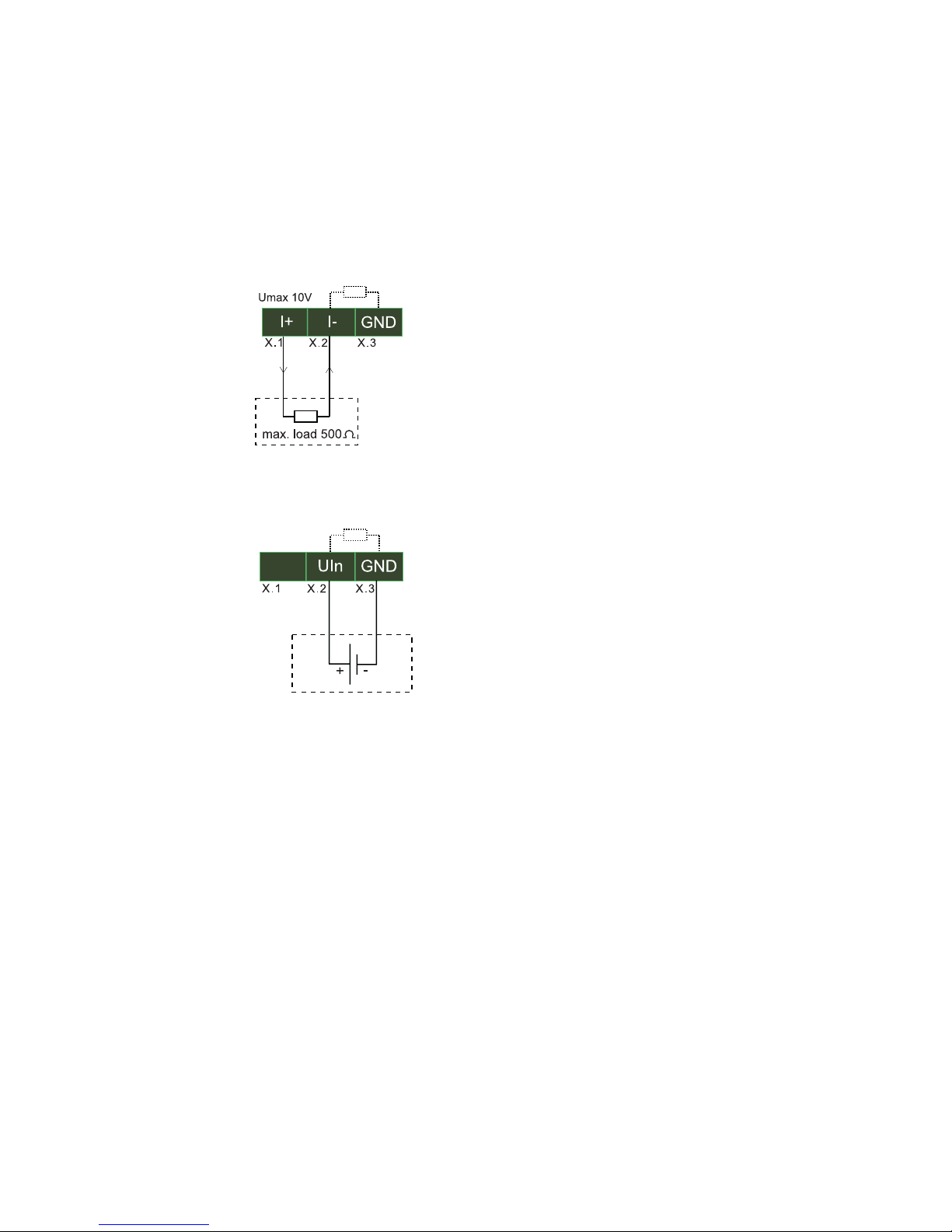
1.2.4 Current output 0..20mA (#57661)
1.2.5 Voltage input 0..10V (#57662)
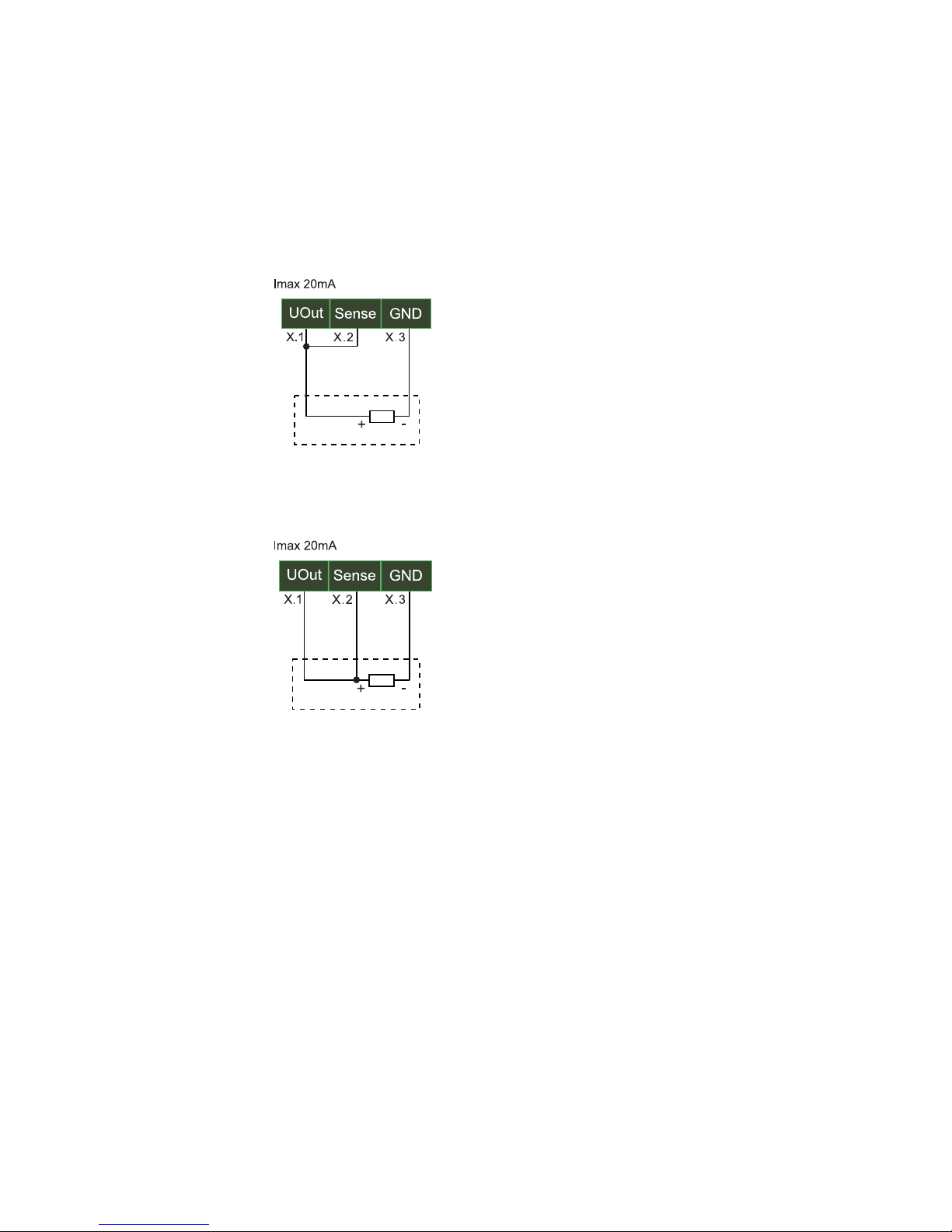
1.2.6 Voltage output (#57662)
The voltage output must be jumpered to the Sense input, which
can be used to measure and regulate the output voltage. This
jumper can be made either directly on the device or at the remote
end. For longer cable distances the jumper should be made on the
remote end so that fluctuations are automatically compensated for.
10
W&T
Jumper directly on the device:
Jumper at the remote end:
Subject to errors and modifications
11
W&T
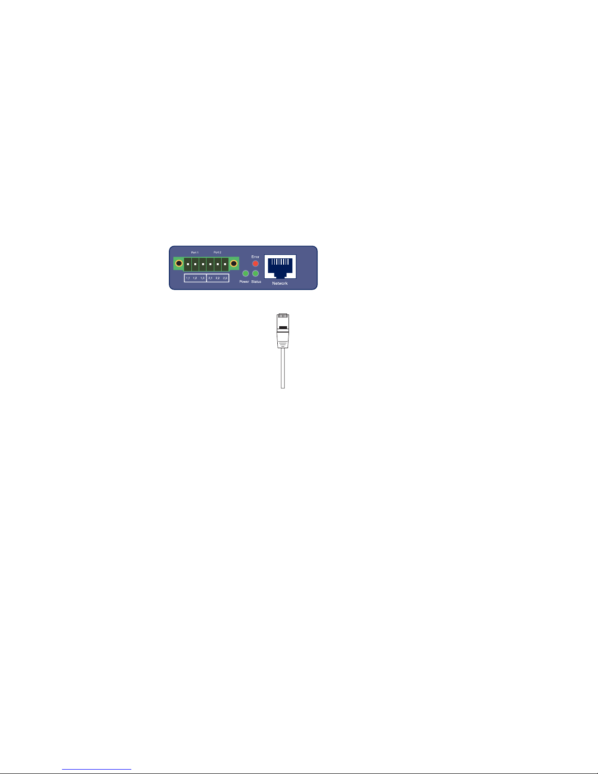
1.3 Network connection
The W&T Web-IO Analog-In/Out has an IEEE 802.3 compatible
network connection on a shielded RJ45 connector. The pin
configuration corresponds to an MDI interface, so that the
connection is made to the hub or swtich using a 1:1 shielded patch
cable..
U
Power-over-Ethernet
The W&T Web-IO Analog-In/Out can obtain its supply voltage
through the network interface in accordance with IEEE802.3af /
Power-over-Internet. The feed comes in over the data pairs or on
the wire pairs not used for 10/100BaseT (see PoE section).
.
12
W&T
1.4 Assigning the IP address using „WuTility“
Once the hardware has been connected to the power supply as
described above, the IP address needed for operating in a TCP/IP
network must be assigned. You should obtrain the correct value for
this parameter from your systems administrator.
The IP address must be unique in the network.
!
There are various ways of assigning the IP address. To make the
procedure as convenient as possible, we have developed the
„WuTility“ tool, which you can download from the WuT homepage
at http://www.wut.de. This procedure is described in the following.
A summary of the options for assigning the IP address can be
found in the Appendix of this manual..
Be sure that the PC you are using to assign the IP address is
located in the same subnet as the W&T unit and that both the PC
and the unit are connected to the network.
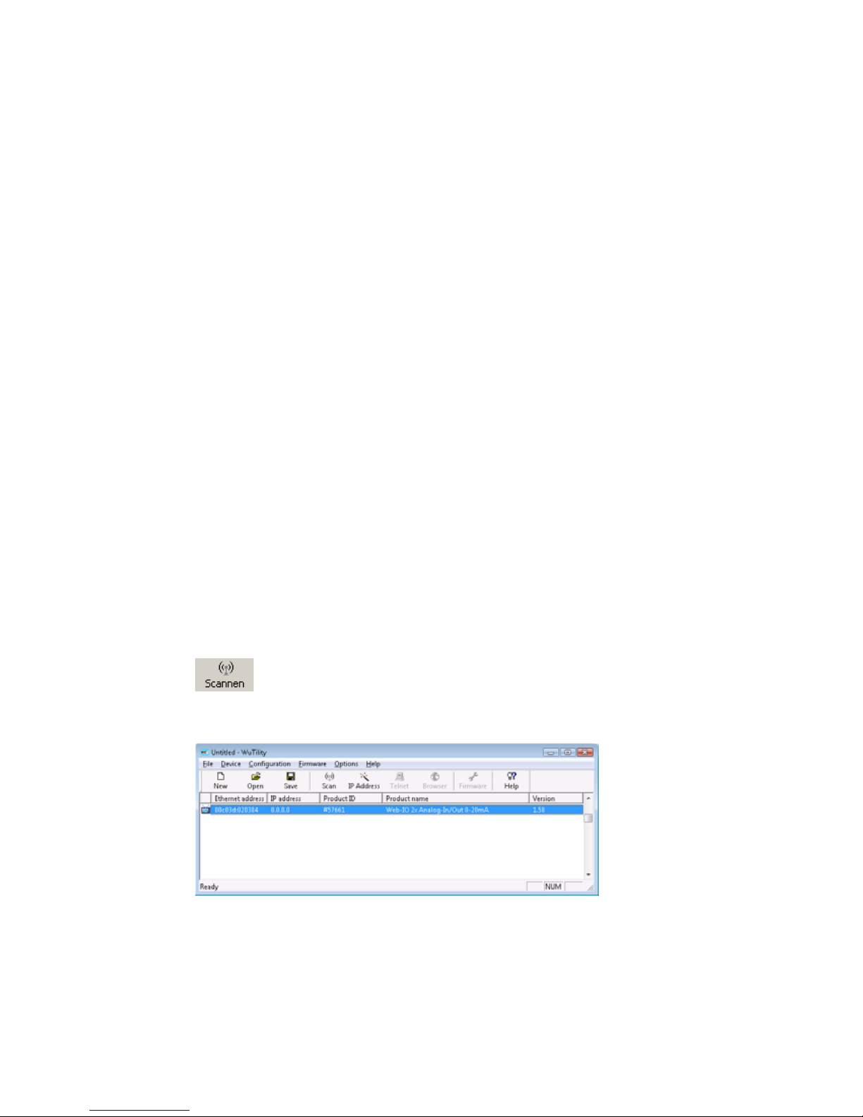
When first started, WuTility automatically searches the local
network for all connected W&T network devices and generates an
inventory list. This search process can be repeated as often as
desired by clicking on the Scan button:
Select your Web-IO from the displayed list based on its MAC
address:
Subject to errors and modifications
13
W&T
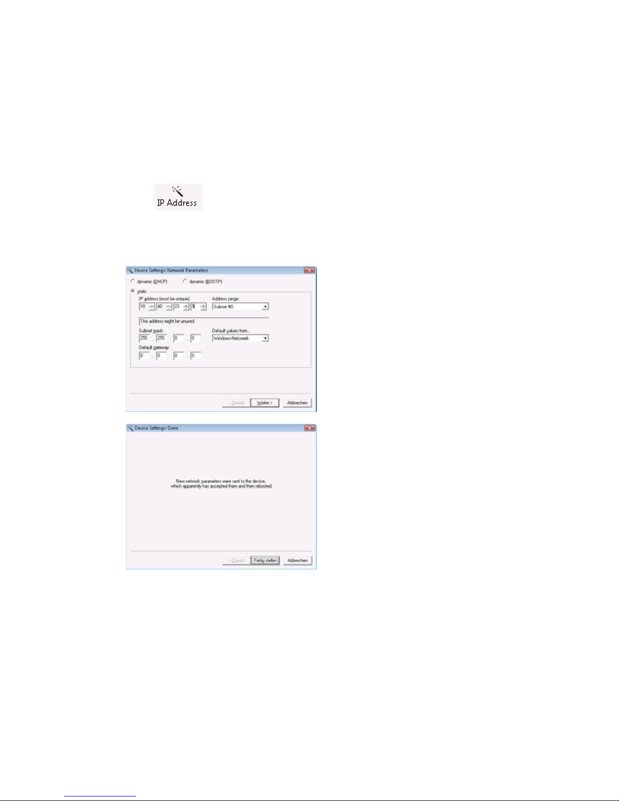
Click on the „IP address“ icon:
In the resulting window enter the desired network parameters for
the device. Clicking on the Next button assigns the network
parameters to the device.
All the columns in the WuTility device list are filled with information.
After clicking on the globe in the WuTIlity menu bar your standard
browser is opened and you see the start page of the device.
14

W&T
1.5 Assigning the IP address using DHCP protocol
Many networks use DHCP (Dynamic Host Configuration
Protocol) or the predecessor protocol BOOTP (described in the
following section) for centralized and dynamic assignment of
the network parameters. DHCP protocol is enabled by factory
default setting, so that in network environments wtih dynamic
IP assignment you need only to connect the W&T Web-IO Analog-In/Out to the network. The following parameters can be set
using DHCP:
• IP address
• Subnet mask
• Gateway address
• DNS server
• Lease time
To prevent unintended address assignments or address
1
changes, we recommend disabling DHCP, BOOTP and
RARP protocols unless they are expressly used in the respective
network environment. W&T Web-IO Analog-In/Out units with
incorrectly assigned IP addresses can be conveniently located and
reconfigured using the WuTility management tool.
1.5.1 Enabling/Disabling DHCP
The factory default setting is for DHCP protocol enabled. To
disable or enable it again later any of the following methods may
be used.
• WuTility management tool
From the device list select the desired W&T Web-IO AnalogIn/Out and click on the IP Address button. In the dialog box
enter the new network parameters you want to assign. Disable
the options BOOTP and DHCP. Click on Next to send the new
configuration data to the W&T Web-IO Analog-In/Out.
Subject to errors and modifications
15

W&T
• Web Based Management
In the menu path Config r Device r Basic Settings r Network the
protocols can be alternatingly enabled or disabled. For detailed
information see the section Assigning basic network parameters..
1.5.2 System Name
To suypport any automatic updating of the DNS system by the
DHCP server the W&T Web-IO Analog-In/Out identifies itself within
the DHCP protocol by its system name. The factory default setting
is WEBIO- followed by the last three places of the Ethernet
address. For example, the factory set system name of a W&T
Web-IO Analog-In/Out with Ethernet address 00:c0:3d:01.02.03 is
WEBIO-010203. The system name of the W&T Web-IO Analog-In/
Out can be changed using Web Based Management.
16

W&T
1.5.3 Lease-Time
The lease time determined and sent by the DHCP server
specifies the term of the assigned IP address. After half the lease time has expired the W&T Web-IO Analog-In/Out attempts to
extend or update the address. If this is not possible before the
lease time expires, for example because the DHCP server can
no longer be reached, the W&T Web-IO Analog-In/Out deletes
the IP address and begins a cyclical search for alternate DHCP
servers for assigning a new IP address.
The lease time associated with the current IP address is no
longer available after a reset. After restarting, therefore, a
corresponding update request is made by the original DHCP
server. If the server cannot be reached at this time the W&T WebIO Analog-In/Out deletes the IP address and begins a cyclical
search for alternate DHCP servers.
If DHCP is enabled, the remaining lease time together with the
current IP address is displaced in seconds in the menu path Home
r Doc r Property.
If the DHCP server is no longer accessible after expiration
1
of the lease time, the W&T Web-IO Analog-In/Out deletes its
IP address. All existing TCP/UDP connections between the W&T
Web-IO Analog-In/Out and other network clients are thereby
closed. To prevent such situations, we recommend configuring the
assigned lease time in the DHCP server to infinite whenever
possible.
Subject to errors and modifications
17

W&T
1.5.4 Reserved IP addresses
The W&T Web-IO Analog-In/Out provides services which can
make use of the other clients in the network as needed. Of course
the current IP address of the W&T Web-IO Analog-In/Out is
needed by these clients in order to open a connection, so that in
these cases it makes sense to reserve a particular IP address for
the W&T Web-IO Analog-In/Out. This is generally done by linking
the IP address to the unique Ethernet address of the unit, which
can be found on the sticker on the housing.
5xxxx [Typ]
EN=00c03d004a05
OK xxxxxx
1.5.5 Dynamic IP addresses
Fully dynamic address assignment, whereby the Web-IO Analog-In/Out is given a different IP address after each restartor
after the lease time expires, is only practical in network
environments with automatic cross-linking between the DHCP
and DNS services. This means when assigning a new IP address
to the Web-IO Analog-In/Out, the DHCP server automatically
updates the DNS system as well. The new address is assigned
to the respective domain name. For detailed information about
your network environment, consult your systems administrator
when in doubt.
Ethernet-address
For time server requests, sending e-mails or other client
applications where the device itself actively seraches for server
services located in the network, dynamic changing IP addresses
can also be used.
18
W&T
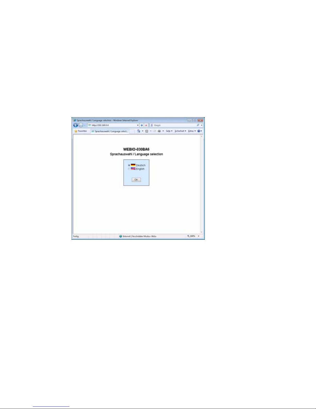
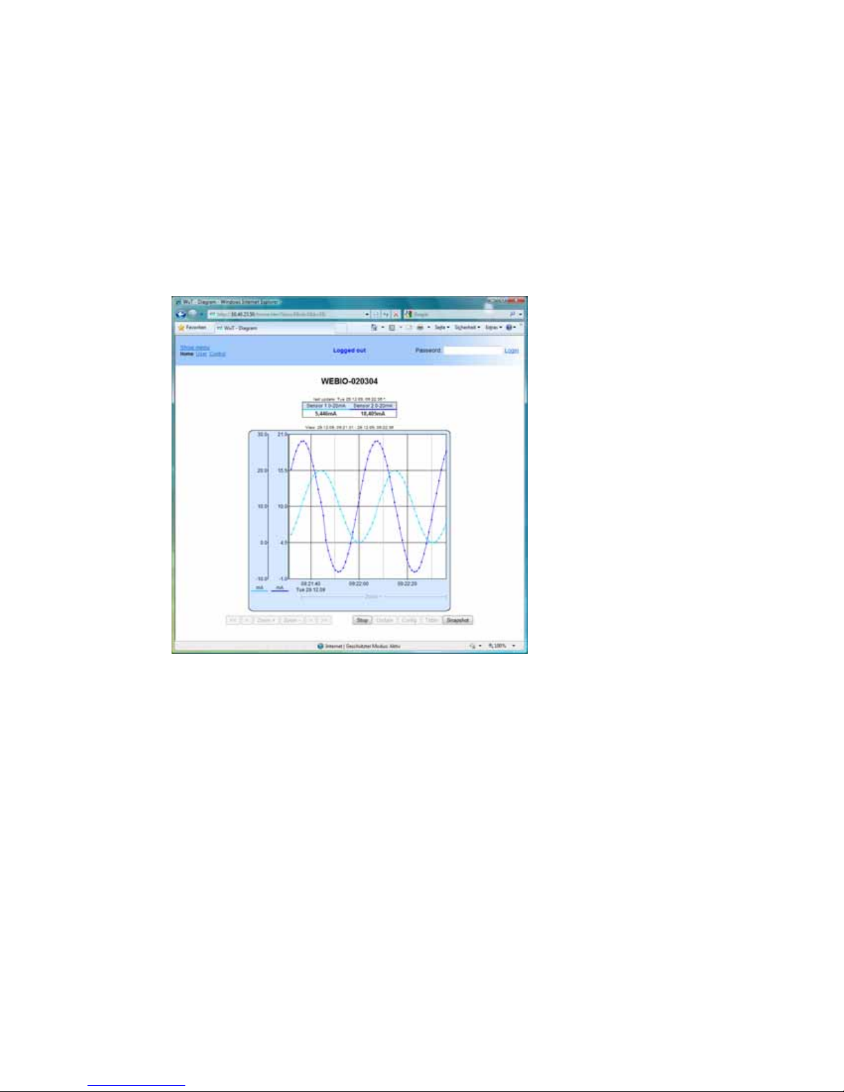
1.6 Start page
As soon as an IP address is assigned, the start page of the
device can be opened in the Web browser:
When first opened you must select the device language. Once
this is done, you are taken to the actual start page of the device.
Subject to errors and modifications
19
W&T
To get to the configuration menu, click above on the page on the
„Show menu“ link. If you assign a password later in the
configuration, you can login here.
Also on this page you can switch to the User page to directly read
out the data logger of the unit.
Display the menu to proceed with the rest of the configuration.
20
W&T
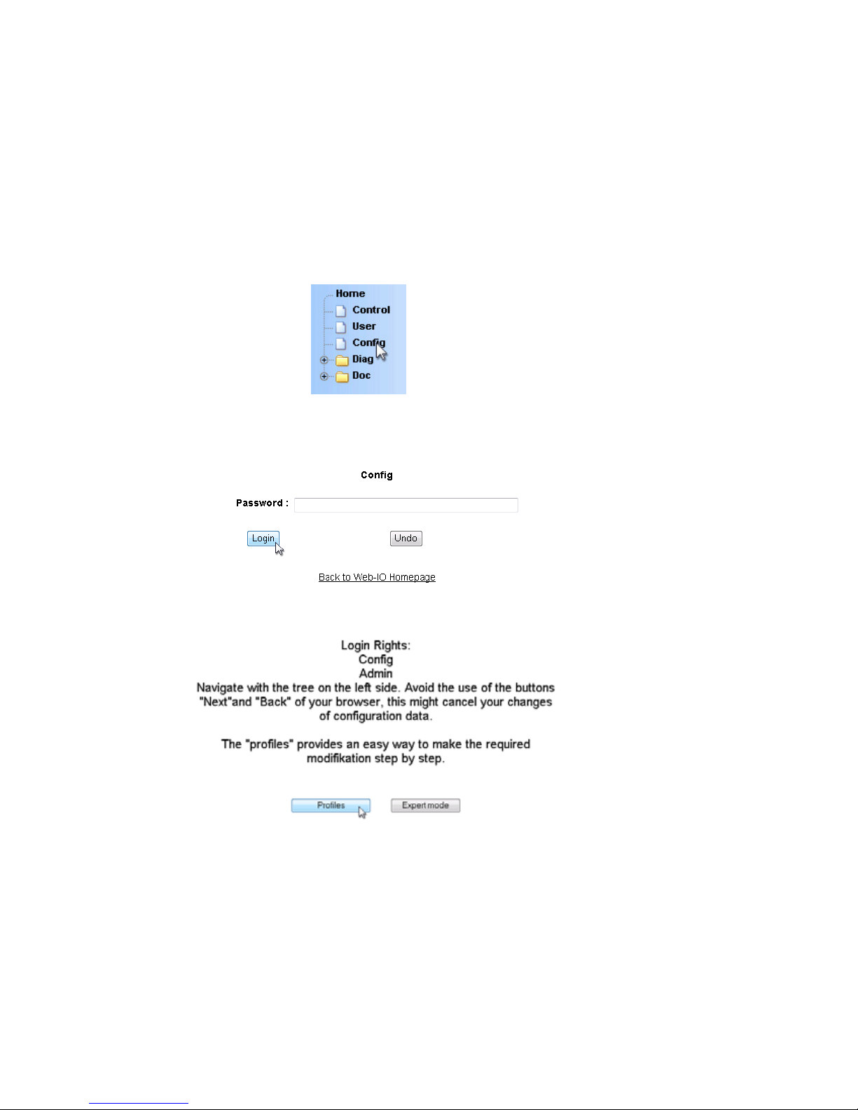
1.7 Assigning the basic network parameters
At left in the configuration tree click on „Config“.
You are now prompted to enter a password. The factory default
setting is for no password, so that you can simply click on the
Login button without entering a password.
On the next page select the configuration path using the profiles.
Select the profile „Network basic parameters“ and click on the
„Show profile“ button“.
Subject to errors and modifications
21

W&T
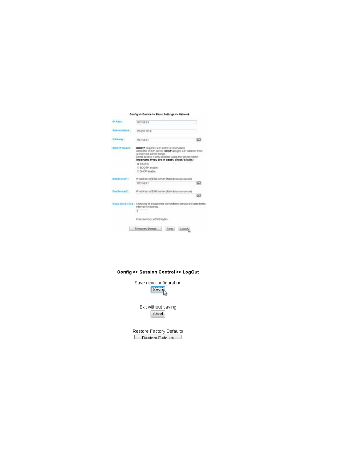
The device now automatically displays the necessary menu points
for this profile. In the configuration menu click on the entry
„Network“.
22
W&T
On the following page enter all the necessary network parameters
and then click on the „Logout“ button.
Clicking on the „Save“ button stores the settings in the device and
closes your configuration session. After the network parameters
are changed the device automatically performs a restart.
The device is now ready to use in your network. For ease of
handling use the additional profiles for adapting the device to your
needs.
Subject to errors and modifications
23
W&T
2 Graphical Representation of the Measurements
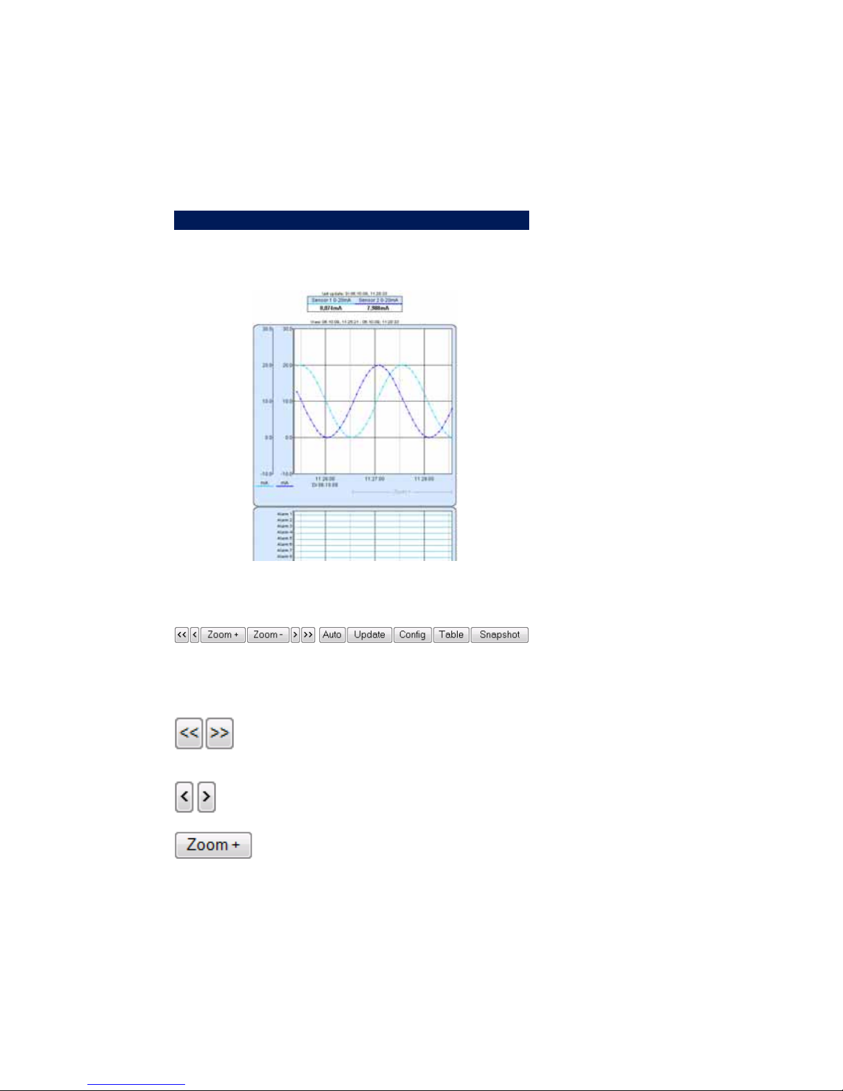
2.1 Basic functions
The device provides a table of the current values and a chart of
the current values on the home.htm page.
The navigation vuttons on the bottom provide the following control
functions.
Scrolls the chart to the right or left by the
size of the display interval.
Scrolls the chart right or left by one unit of
the x-axis.
Zooms in to the area of the chart indicated
by „Zoom +“ on the lower right edge.
24

W&T
Zooms out to the previous zoom level.
Activates automatic updating of the chart.
Updates the display.
Opens the configuration menu beneath the
chart
Displays the values current displayed in the
chart in table format
Opens a new page with a snapshot of the chart
display.
Measured value representation:
Large point: This value is stored in the data
logger of the device.
Small point: This value is a volatile one
which is used only for display and is not
stored in the data logger.
When exiting the zoom level these
values are lost. The connecting lines
!
are only displayed in the zoom level
which represents the memory.
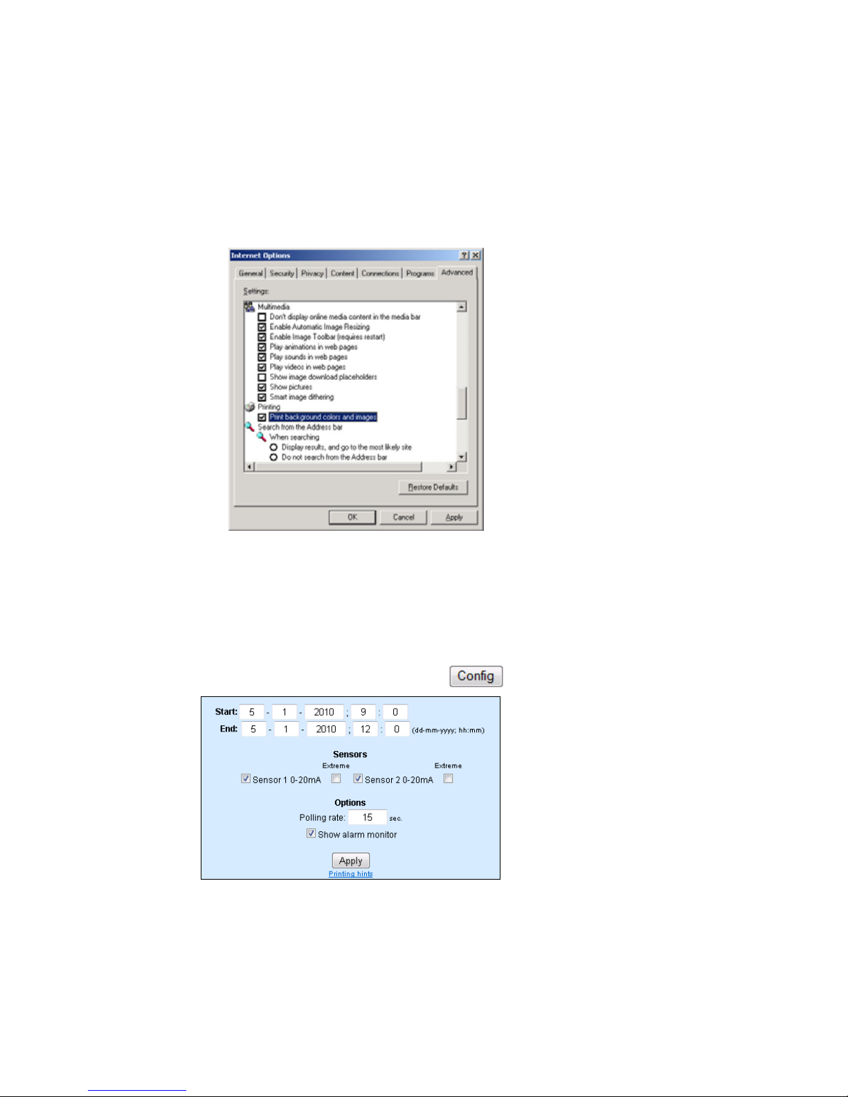
To print out the page containing the graphical display, you must
enable printing of background colors and images in the Internet
options. In Microsoft Internet Explorer this setting is found in
Subject to errors and modifications
25
W&T
Tools -> Internet options -> Advanced
The design and configuration of the graphical display can be
varied. For additional information, see the section Configuring the
graphical display.
2.2 Config-Menu
26

W&T
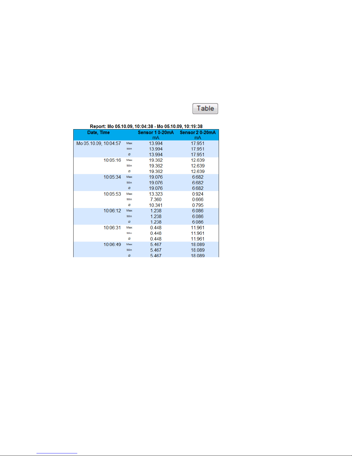
The following functions are available from the configuration menu
below the graphical display:
Start: Specify the starting time point for the x-axis
End: Specify the end time point for the x-axis.
Sensors: Turn individual sensors for the display on and off.
Polling Rate: Enter here the desired polling rate for the graphical
display. The device makes a new value available no sooner than
0.5 seconds. Entering a value of less than 0,.5 has no effect.
Extreme: If in the graphical display a zoom level is selected in
which a display point represents a measurement interval and not
an individual measuring point, this function is used to display the
maximum and miminum measured during this interval. If the zoom
level is selected so that every measurement is displayed, this
function has no effect. If the function is turned off, the average of
the displayed interval is displayed.
Show alarm monitor: Uses a bar graph to show whether the alarm
monitor is active or inactive for the respective alarm.
Apply: The changes made are immediately applied to the graphical
display.
Subject to errors and modifications
27
W&T
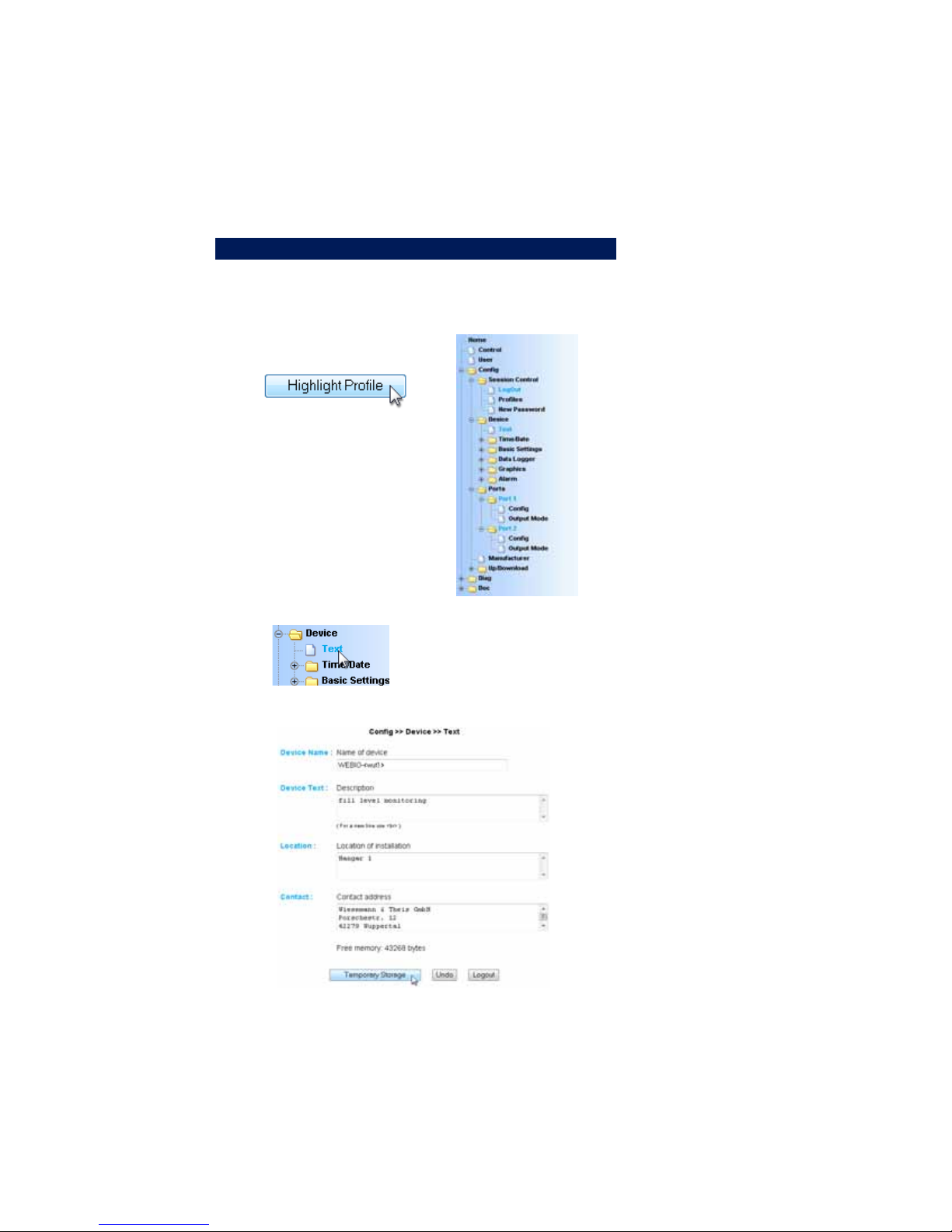
2.3 Table
This function uis used to show the currentlyh displaye dvalues
in table format. As soon as not all the stored values can be
displayed, the following values for the sensor are shown in the
table:
Max: The maximum value in the displayed interval
Min: The minimum value in the displayed interval
Ø: The average value of the displayed interval
28
W&T
3 Other Basic Settings
3.1 Configuring the port and device name
3.1.1 Text
Enter your personal descriptions in the fields and then click on
„Apply“.
Subject to errors and modifications
29
W&T
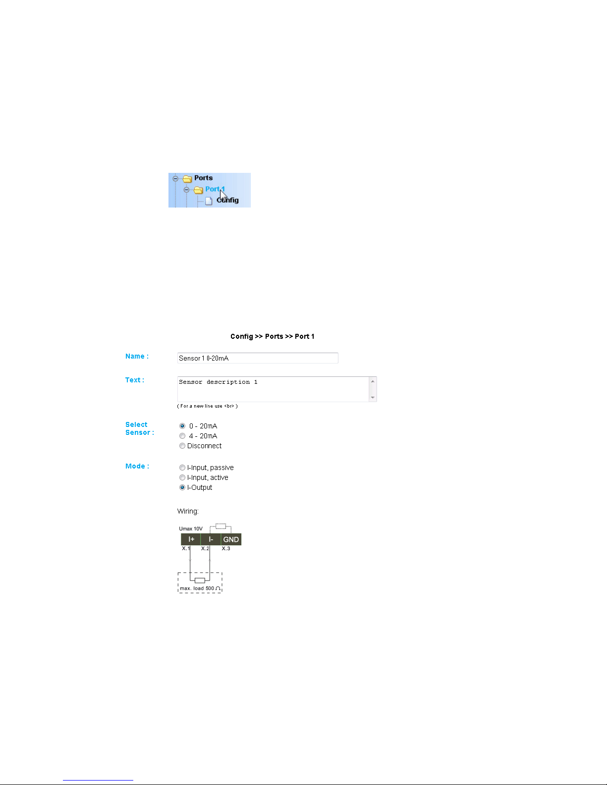
3.1.2 Ports
Port 1..2:
First enter a name and a descriptive text for the port and select
the measuring range for adapting the input wiring for your
measuring point (For model 57661 only: Measuring range 0..20mA
or 4..20mA). To disable the port, select „Disconnect.“
Configuring the current input and output (Model 57661):
30

W&T
Configuring the voltage input and output (Model 57662):
Subject to errors and modifications
31

W&T
3.2 Specifying Output Mode
You must specify which mode you want each individual output to
operate in. The corresponding configuration can be made under
Config >> Ports >> PortX >> Output Mode.
Output Mask:
Here you specify which operating mode is used for each
output. The factory default setting for all ports is HTTP.
Please note that for most of the modes you must make a few
other settings in addition to output mode, such as enabling the
operating mode. Additional information can be found in the
description for the respective operating mode.
32

W&T
Safety State / Timeout / Value
If no network activity is detected for the timeout time set here,
the Web-IO Analog-In/Out sets the outputs to a configurable
value (Safety Value).
After selecting the output modes click on Apply to sent the
settings to the device. Use the Logout button to activate the
settings and then click on Save.
3.3 Compensation of the output controller (57662 only)
During the use of applications, which have a high entrance
capacity, it is necessary to compensate the voltage regulator
to prevent an overshooting of the output value.
Example: Output regulation with entrance capacity of 100µF,
without compensation:
Subject to errors and modifications
33

W&T
This overshooting can be avoided with a compensation value
between 0 and 1000. This value can be configured manually,
or determined automatically. The device adjusts two test pulses
with 80% amplitude at the output. To start the automatic
determination of the compensation click on the button „send
test pulses “.
Please make sure that no sensitive devices are attached
1
to the output to avoid inadvertent output levels.
After clicking the button the device begins with the automatic
compensation. The test pulses with a capacity of 100µF appear
as follows:
34

W&T
Value: The device enters the determined compensation value
automatically. This value is valid immediately. The value can
also be set manually. Subsequently, the desired value which was
present before the determination will be adjusted again.
Mode:
Auto adaptive enable: The device determines the compensation
at run-time. Here no compensation value must be registered.
The disadvantage here is in the fact that constantly changing
capacities must be measured first, until the initial value fits
again correctly.
Use saved value at power on: If this function is activated, the
adjusted compensation value is used immediately after starting
the device.
Example: Output regulation with entrance capacity of 100µF,
with compensation:
Subject to errors and modifications
35

W&T
3.4 HTTP - Controlling outputs in the browser
Access from the browser is probably the simplest way of
working with the Web-IO Analog-In/Out.
To operate the outputs from the browser it is necessary to log
in as Administrator or with Config rights.
After successfuly logging in, the control elements for the
output are enabled using the Control menu point.
36

W&T
The Follow slider checkbox causes the selected output value to
be set as soon as the slide controller is released at a certain
point. At the same time the slide controller automatically
changes its position when the device changes its output value,
for example using TCP commands.
If the Follow slider checkbox is not selected, an input field and
a button appear which can be used to manually set the output.
The value in the input field can also be set using the slide
controller. The entered output value is set as soon as the Set
button is clicked.
3.5 HTTP - Controlling outputs using a command string
You can also use a TCP client in HTTP mode to set the outputs
using HTTP-GET commands. Here you use the expression:
GET /outputaccessX?PW=<password>&State=<value>&
X: Number of the output: 1=Port 1, 2= Port 2
password: If an Admin password is assigned, it must be entered
here in order to be able to set the output value. If no password is
assigned, leave this place blank (...?PW=&...)
Subject to errors and modifications
37

W&T
value: Here you enter the value you want to set on the
respective output. The unit of the value corresponds to the
scale settings you configured under Config >> Ports >> Port X
>> Config.
To set a value of 50 on Channel 2 without an assigned
password, use for example the expression:
GET /outputaccess2?PW=&State=50&
3.6 HTTP - Polling inputs using a command string
Similar to setting the output, both input channels can also be
polled using command strings. What is sent out depends on
the setting GET Header enable under Config >> Device >> Basic
Settings >> HTTP.
If this box is checked the evice sends its IP address in front in the
reply along with the system name and sensor name. If the box is
unchecked only the actual measurement values are output.
The expression for polling the respective port is:
GET /SingleX
X: Number of the input: 1=Port 1, 2= Port 2
Example, Display with option GET Header enable:
10.40.42.44;WEBIO-046EE9;Sensor 1 0-20mA;14.300 mA
Example, Display without option GET Header enable:
14.300 mA
38

W&T
When entering the command string
GET /Single
without a port number the device outputs the values for both
ports separated by semicolons:
10.40.42.44;WEBIO-046EE9;12,000 mA;5,000 mA
or
12.000 mA;5.000 mA
3.7 BINARY - Socket programs with binary structures
The Web-IO Analog-In/Out provides two independent socket
accesses, Binary 1 and Binary 2, for binary data exchange. Both
can be used and configured independently of each other.
Whether the device should use the respective BINARY socket as
a TCP server, TCP client or UDP peer depends on the desired
application
Here is an overview of applications and operating modes for the
Web-IO.
. Customer socket application (binary with password protection)
. TCP-Server
. TCP-Client
. UDP-Peer
. Customer socket application which uses the same structure as
the W&T Digital- EA-Com-Server 50xxx.
. TCP-Server
. TCP-Client
. UDP-Peer
Subject to errors and modifications
39

W&T
. Box-to-Box Master
. TCP-Client
. Box-to-Box Slave
. TCP-Server
. OPC-Device together with the W&T OPC-Server
. TCP-Server
Binary socket access
In this section you will learn how the Web-IO Analog-In/Out can
be accessed from your own professional applications using
sockets with binary structures.
Box-to-Box and OPC device modes are covered in
i
greater detail in the next sections.
3.7.1 Specifying the operating mode
First you must specify whether the Web-IO Analog-In/Out will
be be used in your application as a TCP client, TCP server or
UDP peer.
In the navigation tree Config >> Device >> Basic Settings >>
select Binary 1 if you want to configure the operation mode for
access through Binary 1.
m Necessary access rights: Administrator
40

W&T
After selecting the desired mode and setting Enable Binary send
the setting to the Web-IO Analog-In/Out by clicking on the Apply
button.
For access from your own application programs the developer is
provided with two levels of the socket programming.
1. Socket Device (password protected access)
2. Compatible 50xxx (This mode is compatible with the binary
structure which was alrelady used by the older W&T Digital I/O
Com-Servers.)
Both access options use the same binary structures and differ only
in the absence of password protection in Compatible 50xxx mode.
3.7.2 The Web-IO Analog-In/Out as Socket-Server
To operate the Web-IO Analog-In/Out as a socket server, a few
additional settings must be made.
In the navigation tree select Config >> Device >> Basic Settings
>> Binary 1>> TCP Server
m Necessary access rights: Administrator
Subject to errors and modifications
41

W&T
Local Port
The local port on the device is factory set to 49153. If your
application requires a different local port for the Web-IO, enter the
desired port number in the Local Port field.
Client HTTP Port
Is only relevant for OPC and Box2Box modes and specifies the
HTTP port on which a control line should open a connection to the
OPC server or slave box.
Unless otherwise specified, Port 80 should always be used here.
Binary Trigger
Enter here a hysteresis value for both ports which, when it is
reached or exceeded, should trigger sending of data to the client
application (important for event-triggered applications).
42

W&T
Application Mode
Select here:
. Socket Device - If you want access to the Web-IO password
protected.
. Compatible 50xxx - If you want access to the Web-IO using
applications which were programmed fo the older Digital I/O
Com-Servers. You can also use this mode for new applications
that do not require password protection.
A more detailed discussion of Box2Box Slave and
i
sections.
After all your settings have been made, send them to the Web-IO
by clicking on the Apply button.
In addition, the ports used must be enabled for Binary Mode.
In the navigation tree select Config >> Ports >> Port X >> Output
Mode and highlight the desired binary access.
OPC Device modes can be found in the corresponding
m Necessary access rights: Administrator
Subject to errors and modifications
43

W&T
After all the entries have been made, send the setting by
clicking on the Logout button. Click on the Save button to
activate the settings.
All configuration possibilities shown for Binary 1
i
may also be used for Binary 2.
44

W&T
3.7.3 The Web-IO as Socket-Client
To operate the Web-IO as a socket client, a few additional
settings must be made
In the navigation tree select Config >> Device >> Basic Settings
>> Binary 1>> TCP Client
m Necessary access rights: Administrator
Local Port
The local port of the Web-IO is factory set to AUTO. If your
application requires a special local port for the Web-IO, enter the
desired port number in the Local Port field.
Subject to errors and modifications
45

W&T
Server PortServer Port
Server Port
Server PortServer Port
Enter here the port number the server application should use
to receive the connection.
Server HTTP Port
Is only relevant for Box2Box mode and specifies the HTTP port on
which a control line should open a connection to the slave box.
Unless otherwise specified, always use Port 80 here.
Server IP AddrServer IP Addr
Server IP Addr
Server IP AddrServer IP Addr
Enter here the IP address of the server.
Server PasswordServer Password
Server Password
Server PasswordServer Password
A server password only needs to be entered if the Web-IO is used
as a Box-to-Box Master or needs to access a different Web-IO as
a TCP client in Server mode. More about this in the Box-to-Box
section.
Inactive Timeout
Here a timer is configured. After the time expires, the Web-IO
closes the TCP connection. The value is entered in decimal land
in 100ms increments. The timer is reset during an active
connection when data are exchanged.
Example: The value 10 corresponds to one second. If no data
transfer is detected for one second, the Web-IO closes the
connection.
If no value is entered, automatic connection closing is disabled..
Binary TriggerBinary Trigger
Binary Trigger
Binary TriggerBinary Trigger
Here you select the ports whose status change should act as a
trigger for opening the TCP connection and sending data to the
server (important for event-triggered applications).
Interval
If you want the status of the inputs to be sent cyclically to the
server application, you can enter here the interval iln 100ms
increments.
46

W&T
Example: A value of 300 corresponds to 30 seconds.
Please note that for connections using fee-based dial-up
1
connections too small an interval may result in the
connection not being closed, in turn resulting in permanent fees!
Mode
Select here:
. Socket Device - If you want access to the Web-IO password
protected.
. Compatible 50xxx - If you want access to the Web-IO using
applications which were programmed fo the older Digital I/O
Com-Servers. You can also use this mode for new applications
that do not require password protection.
More detailed information about Box2Box Master mode can be
found in the Box-to-Box section.
After all your settings have been made, send them to the Web-IO
by clicking on the Apply button.
In addition you must enable the used outputs for Binary mode.
Now in the navigation tree select Config >> Ports >> Port X >>
Output Mode and highlight the desired Binary access.
m Necessary access rights: Administrator
Subject to errors and modifications
47

W&T
After you have made all your settings, send them by clicking
on the Logout button. Clicking on the Save button activates the
settings.
3.7.4 The Web-IO as UDP-Peer
To use the Web-IO as a UDP peer a few additional settings must
be made.
In the navigation tree select Config >> Device >> Basic Settings
>> Binary 1>> UDP Peer
m Necessary access rights: Administrator
48

W&T
Local Port
The local port on the device is factory set to 45889. If your
application requires a different local port for the Web-IO, enter the
desired port number in the Local Port field..
Remote Port
Enter here the port number you want the UDP application to use
for receiving data when communicating with the Web-IO.
Remote IP Addr
Enter here the IP address of the communication partner.
Binary Trigger
Enter here the inputs whose change of state should be used as
the trigger for sending a UDP datagram (important for eventtriggered applications).
Interval
If you want the status of the inputs to be sent cyclically to the
communication partner, enter here the interval in 100ms
Subject to errors and modifications
49

W&T
increments.
Example: A value of 300 corresponds to 30 seconds.
Please note that for connections using fee-based dial-up
1
connections too small an interval may result in the
connection not being closed, in turn resulting in permanent fees!
Application Mode
In the configuration as UDP peer there is no difference between
Socket Device and Compatible 50xxx modes.
After all your settings have been made, send them to the Web-IO
by clicking on the Apply button.
In addition you must enable the used outputs for Binary mode.
Now in the navigation tree select Config >> Ports >> Port X >>
Output Mode and highlight the desired Binary access.
m Necessary access rights: Administrator
After you have made all your settings, send them by clicking on
the Logout button. Clicking on the Save button activates
settings.
50

W&T
3.7.5 Password protection
As already mentioned earlier, the Web-IO enables you in TCP
server mode to protect access through the application using a
password.
Before the actual connection to the Web-IO is opened, the BinInfo
structure defined here must be sent over a separate TCP
connection to the HTTP port (factory set to Port 80) on the WebIO.
For the reply the Web-IO also uses the structure BinInfo.
BinInfo BYTE[n]0 HTTPlogin n = 14 bytes + password
(PC <-> Web-IO WORD dummy always 0
The individual variables of the structure are filled in as follows:
BYTE type type of request
BYTE subtype additional information
LONG srcip source ip-address
WORD srcport source port
WORD destport destination port
HTTPLogin[n]
Ist ein Bytefeld bzw. String, der sich aus einem Loginstring und
dem verwendeten Administrator-Passwort zusammen setzt.
GET /bin?LPW=
<Administator Passwort>
&
n stands for the number of bytes used and corresponds to 14 +
the length of the password. The length of the password is limited
to 31 characters.
In the reply from the Web-IO HTTPLogin is always 8 characters in
length and contains the following string:
GET /bin
Dummy
Slash between the ASCII and the binary section of the structure.
Subject to errors and modifications
51

W&T
Is always = 0x00
Type
Determines the type in which Binary mode is used.
The application must enter 0x04 here in order to open a TCP
connection.
In its reply the Web-IO enters
0x02 if the connection request was accepted
0x03 if the connection request was denied.
SubType
Provides more details about the status of the connection request.
The application always sends 0x00.
The Web-IO replies with
0x01 BINSUBTYPE_OK, // wenn die Verbindungsanforderung akzeptiert wurde.
0x02 BINSUBTYPE_NO_ACCESS,// wenn bereits eine Verbindung besteht
0x04 BINSUBTYPE_WAIT, // wenn die Verbindung erst nach einem
// Timeout hergestellt werden darf
0x07 BINSUBTYPE_PW_MISMATCH, // bei falschem Passwort
0x08 BINSUBTYPE_DEST_PORT_MISMATCH, // bei falschem Destination Port
0x09 BINSUBTYPE_MODUS_MISMATCH, // bei falschem Modus
If 0x01 or 0x04 was received, the actual data connection can be
opened.
SrcPort
The client application alwlays enters a 0 here.
The Web-IO returns here the opened server port (e.g. 49153 for
Binary 1). If the login attempt has failed, the Web-IO enters 80.
52

W&T
DestPort
The client application enters here which port will be used for the
connection (e.g. 49153 for Binary 1 or 49154 for Binary 2).
The Web-IO always returns 0
The connection through which the BinInfo structure was
transmitted is automatically closed by the Web-IO.
3.7.6 BINARY - The IO structures
To enable simple communication between the user program on
the computer and the Web-IO, there are a limited number of
structures (variable fields) which define the format and content
of the data exchanged between the user program and the WebIO.
IO structures are provided for the following functions:
. Reading the inputs
. Setting the outputs
. Parameterizing the cyclical and automatic messaging when
there is a status change
The user program uses the easy to use socket4 interface
(Windows: WinSock, UNIX, Linux: Berkley
Sockets) for exchanging data in the form of these IO structures
with the Web-IO over the network via TCP/IP.
The IO structures do not depend on the network protocol used
(TCP or UDP).
Socket-Schnittstelle
Ethernet-Header Ethernet-Nutzdaten
IP-Header
IP-Nutzdaten
IO-Strukturen
UDP-/TCP-NutzdatenUDP-/TCP-Header
Which of the two protocols are used, UDP or TCP, depends on
the type of application. Both protocols offer advantages and
Subject to errors and modifications
53

W&T
disadvantages which must be considered depending on the
application you want to create.
Help with socket programming including the basics of
i
TCP/IP can be found in a short and clear form in our
manual „Ready in 1 day for TCP/IP Sockets“. Program examples
for client/server applications under TCP/IP are located on our
homepage at http://www.wut.de.
3.7.7 Definition of the IO structures
To be able to unambiguously identify and process the contents
of a packet, in BINARY mode all the data must be sent to the
Web-IO in the form of these IO structures regardless of whether
50xxx-compatible or Socket Client mode is used..
All structures begin with the same header which consists of the
following 4 WORDS (16bit_Integer):
Structure-Header WORD send_sequence always 0
send_sequence, rec_sequence
For compatibilty reasons with respect to older Digital I/O ComServers send_sequence and rec_sequence are provided but not
used. Both values are always 0.
54
WORD rec_sequence always 0
WORD struct_type identifies the structure
WORD length length of the structure in bytes

W&T
struct_type
The value struct_type identifies which structure is being used.
Both the PC application and the Web-IO decide when the data
are received how the structure should be processed based on
the value struct_type.
length
length indicates the total length of the structure in bytes, i.e.
including the first 4 WORDs.
The result is the following packet structure:
Structure buildup WORD send_sequence always 0
Note: The following applies for all IO structures
WORD rec_sequence always 0
WORD struct_type identifies the structure
WORD length length of the structure in bytes
Variable ............... depends on the function
............... ............... additional variables
1
A WORD corresponds to 16bit_integer (unsigned)
A BYTE corresponds to one byte (8 bits)
A LONG corresponds to a 232bit_integer (unsigned)
Hexadecimal format 0x in front of the value
When sending and receiving, the following applies for
1
all structure variables: Low-Byte first.
The following structure
Example WORD send_sequence 0x0000
would look as follows when sent on the network:
send_sequence rec_sequence struct_type length
low byte high byte low byte high byte low byte high byte low byte high byte
00 00 00 00 01 00 08 00
WORD rec_sequence 0x0000
WORD struct_type 0x0001
WORD length 0x0008
Subject to errors and modifications
55

W&T
3.7.8 Working with the IO structures
In the next section we will explain the individual structures and
the corresponding values of the variables send_sequence,
rec_sequence, struct_type and length, which are used to begin
each packet.
IO-Structure ReadRegister
Sending this structure to the Web-IO causes it to send the status
of the port to the user program. The packet consists only of these
four WORDs. This structure is used only by the user program, and
the Web-IO always responds by sending the structure
AnalogRegisterState.
ReadDiagnosis WORD send_sequence always 0
(PC -> Web-IO) WORD rec_sequence always 0
IO-Structure AnalogRegisterState
The Web-IO Analog-In/Out uses this structure to lsend the
state of both ports. This structure is sent when the user program has sent the structure ReadRegister to the Web-IO, or
when this structure was used to set an output value.
WORD struct_type 0x00D1
WORD length 0x0008
AnalogRegisterState WORD send_sequence always 0
(Web-IO <-> PC) WORD rec_sequence always 0
WORD struct_type 0x01B8
WORD length 0x0014
LONG word_anz 2
LONG Port 1 Port1 State (in 1/1000 %)
LONG Port 2 Port2 State (in 1/1000 %)
This structure is also used for sending the output value of the port
for the Web-IO Analog-In/Out. When the user program sends this
structure to the Web-IO, the Web-IO sets the outputs according to
the value sent on Port 1 and Port 2. Here the value is not
transmitted in the configured units, but rather always in 1/1000 %
of the current or voltage present. An output value of 15.4mA must
be sent as 77000 x 1/1000 %, or 0x012CC8.
When the Web-IO sends this structure to the user program, Port 1
and Port 2 have the value correspolnding to the input state.
56

W&T
foff
f
f
IO structure Send Mode
This structure determines the trigger conditions the Web-IO
Analog-In/Out uses to send the state of the ports to the user
program. The trigger can be configured for state changes on both
ports. The respective hysteresis for the trigger must be set in the
Web configuration
SendMode WORD send_sequence always 0
(PC -> Web-IO) WORD rec_sequence always 0
The following combinations can be configured as input_trigger
variables:
WORD struct_type 0x0010
WORD length 0x000C
WORD input_trigger 0x0000 - 0x0003
WORD interval Intervall data packets in 100ms
0x0000 of
0x0001 on of
0x0002 of
0x0003 on on
Port 1 Port 2
on
IO structure ReadDiagnosis
If the Web-IO detects a communications or system error, the error
is listed on the HTML page and can be read from the browser.
Since error management via browser is not always available for
program-controlled applications, the error status of the Web-IO can
be polled using the structure ReadDiagnosis.
ReadDiagnosis WORD send_sequence always 0
(PC -> Web-IO) WORD rec_sequence always 0
WORD struct_type 0x00D1
WORD length 0x0008
In reply the Web-IO sends a Diagnosis type structure.
IO structure Diagnosis
The Web-IO sends the Diagnosis structure in reply to the
ReadDiagnosis structure.
Subject to errors and modifications
57

W&T
Diagnosis WORD send_sequence always 0
(Web-IO -> PC) WORD rec_sequence always 0
The variable diag_error_count returns how many different errors
are currently in the error log. The Web-IO differentiates a variety
of different error states, whereby each set bit in the variables
diag_errorbits0, diag_errorbits1 and diag_errorbits2 stands for an
error type.
The exact text description can be opened using TCP Port 80.
IO structure ClearDiagnosis
This structure is used to clear the error log in the Web-IO.
ClearDiagnosis WORD send_sequence always 0
(PC -> Web-IO) WORD rec_sequence always 0
WORD struct_type 0x00D0
WORD length 0x001C
LONG word_anz in this version 4
LONG diag_error_count quantity of pending errors
LONG diag_errorbits0 binary error encoding
LONG diag_errorbits1
LONG diag_errorbits2
WORD struct_type 0x00D2
WORD length 0x0008
IO structure Options
This structure is used to set certain options in the Web-IO. 32 bits
are available for this in the options variable.
Options WORD send_sequence always 0
(PC -> Web-IO) WORD rec_sequence always 0
WORD struct_type 0x01F0
WORD length 0x0010
LONG word_anz in this version 1
LONG options binary option encoding
In the current version of the Web-IO only Bit 0 in the options
variable is used.
58

W&T
Bit 0 = 1 //The Web-IO returns the structure
AnalogRegisterState when an output value is set.
Bit 0 = 0 //The Web-IO sends no reply whyen an output
value is set.
To reliably receive the state in the reply after setting the output
value(s), a time of at least 150ms should be kept between two
output changing accesses.
Subject to errors and modifications
59

W&T
3. 8 Box-to-Box
In this mode the inputs of a Web-IO Analog are transferred to
the outputs of a second Web-IO and vice-versa. In this way you
can for example send signals from one location to another ove
a WAN connection.
With Box-to-Box connections a Web-IO assumes the function
of the Master.
The second Web-IO operates as a Slave. The Slave waits for the
Master to open the connection.
Both the Master and the Slave Web-IO need to be correspondingly
configured.
3.8.1 Configuring the Slave Web-IO
m Necessary access rights: Administrator
In the navigation tree of the Slave Web-IO select Config >>
Device >> Basic Settings >> Binary 1
60

W&T
For Operation Mode set TCP-Server mode and activate Enable
Binary.
Then click on the Apply button to send the changes to the WebIO.
Now in the navigation tree select: Config >> Device >> Basic
Settings >> Binary1 >> TCP-Server.
Subject to errors and modifications
61

W&T
Local Port:
Unless your network administrator has informed you otherwise, the
factory default set Port 49153 may be used.
One reason for changing the factory default set local port may
be for example a fireweall which permits access only to a
particular port.
In any case the set local port on the Slave must be
1
identical to the Server Port entry for the Master.
Client HTTP Port
Specifies which HTTP port to be used for opening the control
connection to the Master box.
Unless otherwise specified, always use Port 80 here.
Binary Trigger:
Here you activate the inputs which are to set the corresponding
outputs on the Master.
The Web-IO Anaog-In/Out allows simultaneous access to
i
the inputs from various modes..
This means for example that the inputs which control the outputs
on the Master Web-IO can at the same time be read out over
HTTP.
Application Mode
Select Box2Box Slave
After all the parameters have been entered, confirm by clicking on
the Apply button.
Now in the navigation tree select: Config >> Ports >> Port 1 >>
Output Mode
62

W&T
Activate the outputs to be set by the corresponding inputs on
the Slave for Binary 1 and confirm by clicking on the Apply
button.
The outputs activated for Box-to-Box are no longer accessible
for other modes.
Next the new settings still need to be activated. Use the Logout
button or select Config >> Session Control >> LogOut.
3.8.2 Configuring the Master
m Necessary access rights: Administrator
In the navigation tree select: Config >> Device >> Basic Settings
>> Binary1
For Operation Mode select TCP-Client mode.
Subject to errors and modifications
63

W&T
Then click on the Apply button to send the settings to the Web-IO.
64

W&T
Now in the navigation tree select: Config >> Device >> Basic
Settings >> Binary1 >> TCP-Client.
The following parameters must be entered:
Local Port:
Unless otherwise specified by your network administrator, the
factory default setting AUTO can be used.
ServerPort:
Here the Local Port set for the Slave must be entered. Here again
the basic setting 49153 can be used unless otherwise specified by
the network administrator.
Local Port and Slave Port do not necessarily have to be
i
set the same as the factory default settings.
One reason for changing the factory default settings for Local and
Slave Port may be for example a fireweall which permits access
only to a particular port.
Server HTTP Port
Specifies the HTTP port on which the control connection is to be
opened to the Slave box.
Unless otherwise specified, always use Port 80 here.
Server IP Addr:
Enter here the IP address of the Web-IO to be used as a Slave.
Server Password:
Here the administrator password of the Slave-IO is entered. If no
password has been assigned for the Slave, this field remains
blank.
Inactive Timeout
This parameter has no function in Box-to-Box mode, since a
permanent connection is desired.
Subject to errors and modifications
65

W&T
Binary Trigger:
Activate here the inputs which the corresponding outputs
should set for the Slave.
The Web-IO Anaog-In/Out allows simultaneous access to
i
the inputs from various modes..
This means for example that the inputs which control the outputs
on the Master Web-IO can at the same time be read out over
HTTP.
Interval:
If no interval is entered, the state of the inputs is sent to the
outputs of the other respective Box-to-Box partner whenever there
is a change. By entering an interval the state is also sent cyclically
even when there is no change.
If two locations are connected to each other over a fee-
1
based ISDN line, use of an interval is discouraged since the
ISDN connection may either be never disconnected or often
reopened depending on the timeout and interval.
Application Mode
Select Box2Box Master
After all the parameters have been entered confirm by clicking on
the Apply button.
Now in the navigation tree select: Config >> Ports >> Port 1 >>
Output Mode
66

W&T
Activate here the outputs which are to be set by the
corresponding inputs on the Slave for Binary 1 and confirm by
clicking on the Apply button.
In contrast to the inputs, the outputs activated for Box-to-Box
mode are no longer accessible for other modes.
Now the new settings still need to be activated. Use the Logout
button or select Config >> Session Control >> LogOut.
After clicking on the Save button all the settings are updated in the
Web-IO and the start page is reopened in the default user mode.
The Master Web-IO attempts then to open a connection to the
Slaqve Web-IO. All functions described here for Binary 1 can of
course also be used under Binary 2. For example a Web-IO A in
the Binary 1 area can be configured so that Input 1 operates Box
to Box wi6th a Web-IO B. In the Binary 2 area Input 2 can then be
configured so that it works together Box-to-Box with another WebIO.
3.8.3 Determining Box-to-Box connection status
m Necessary access rights: Administrator
The connection status of a Box-to-Box connection can be
queried using the navigation tree under Diag >> Test >> Out-
put Config.
Here you are shown in which mode the individual inputs are
currently working. In addition the current status of a Box-to-Box
connection is displayed in the footer of the Web page.
Subject to errors and modifications
67

W&T
3.8.4 Quitting Box-to-Box mode
Box-to-Box mode only for the Master
m Necessary access rights: Administrator
Quitting Box-to-Box mode should always be done by configuring
the Master correspondingly. Master and Slave Web-IO must be
connected in the network. In the navigation tree select des Masters
: Config >> Device >> Basic Settings >> Binary1 >> TCP Client
and delete the entry for Server IP Addr. Also set Application Mode
to Socket Client.
Confirm by clicking on the Apply button.
Then set under Config >> Device >> Basic Settings >> Binary1
>> den Operation Mode to TCP Server .
Confirm by clicking on the Apply button.
Now in the navigation tree for the Master select: Config >> Ports
>> Port X >> Output Mode and set the outputs you want to operate
Box-to-Box to HTTP.
Confirm by clicking on the Apply button. Now the changed
settings still need to be activated. Use the Logout button or
select Config >> Session Control >> LogOut.
After clicking on the Save button all the settings are updated in
the Web-IO and the start page is reopened in the default user
mode.
Quitting Box-to-Box mode for the Slave Web-IO
m Necessary access rights: Administrator
In the navigation tree select des Slave: Config >> Device >> Basic
Settings >> Binary1 >> TCP Server and set Application Mode to
Socket Device.
Confirm by clicking on the Apply button.
68

W&T
Nun In the navigation tree select Config >> Ports >> Port X >>
Output Mode and set the outputs which are no longer to operate
Box-to-Box to HTTP.
Confirm by clicking on the Apply button. Now the changed
settings still need to be activated. Use the Logout button or
select Config >> Session Control >> LogOut.
After clicking on the Save button all the settings are updated in
the Web-IO and the start page is reopened in the default user
mode.
3.8.5 Quitting Box-to-Box mode only for the Slave Web-IO
If the Master is no longer available, for example because there
is no network connection but you still want to deactivate Boxto-Box mode for the Slave, in the navigation tree select
Config >> Session Control >> LogOut.
The configuration frame contains an addition button called
Stop Box2Box Slave.
Subject to errors and modifications
69

W&T
If this button is not displayed, first click on the Reset button.
The Web-IO is restarted.
After logging in again and opening Config >> Session
Control >> LogOut the Stopp Box2Box Slave button will be shown.
Clicking on the button resets the Slave to Box-to-Box mode.
70

W&T
3.9 OPC - Standardized access
OPC (OLE for Process Control) is a software interface for
accessing process data based on OLE technology from Microsoft.
Application programs such as visualization systems which use this
interface are called OPC clients. On the opposite side of the
interface are OPC servers. These are device drivers which
represent certain hardware in abstract form as a set of OPC
variables.
The OPC server used here implements the specifications OPC
Data Access 2.0 and Alarms & Events. The server controls devices
in the W&T Web-IO product families, but also serial Com-Servers
and the older Digital I/O Server.
In terms of the architecture this is a system service running in the
background and a monolithic application which contains the
operating elements for configuration and diagnostics.
3.9.1 Installing the OPC-Server
The OPC server can be found on the product CD included with
the Web-IO, in the Web-IO Digital section.
On our Web site www.WuT.de you will find at left the
„Article number search“ function. Enter here for example
g
article number 57661, select „Tools“ from the field below and
click on „Go.“. On the page that then opens select the link „OPCServer.“
For ease of downloading the required files are compressed in a Zip
file. Save the extracted file in any desired directory on your hard
drive (e.g. C:/Temp). Start the setup program by for example
selecting Run from the Start menu and then entering:
„C\Temp\opc_en.msi“ (choose the version for your language). This
installs and registers the OPC server on your computer.
The OLE server name which OPC clients will need to specify later
in order to connect to the server is: Wiesemann-Theis.Network-IO.
Subject to errors and modifications
71

W&T
The OPC server starts automatically upon such requests. To
configure the server you can also run it manually. A corresponding
entry W&T OPC-Server Version 4 can be found in the Start menu
under „Programs.“
3.9.2 Uninstalling
You can remove the OPC server using the control panel
component „Software.“ It is listed there under OPC-Server for
network-I/O devices Version 4.
3.9.3 Configuring
First start the OPC server. For normal installations you will find
the corresponding start icon on your Windows interface under
Start >> Programs >> W&T OPC-Server Version 4
Click on the Web-IO icon or in the menu on Device >> New I/O
device.
The following window opens:
72

W&T
Host name or IP address: Must agree with the IP address which
was assigned to the unit. If there is also a DNS name for the
address, you can also use this instead of a number combination.
HTTP port: Should normally be 80
. The port number entered here is also used for opening the
external brows
er („Web-Browser“ button“)
Device type: In case of doubt the „Identify“ function can help to
select the proper type here. Some input fields with unneeded
parameters may be deactivated after a selection is made.
Passwort: Here you can enter the Config or the Administrator
password which was specified for the unit.
TCP-Port: The factory preset is for Port 49153. For the Web-IO
Analog In/Out check the corresponding setting in the Web menu
of the unit.
Subject to errors and modifications
73

W&T
OPC Device name: All OPC variables for a device begin with a
common (and unique) name component which you can specify
here.
Adjust timing:
The amount of network traffic between the OPC server and
devices depends essentially on the behavior of the OPC client: The
more frequently a client requests updating of DA items, the more
data must be sent over the network.
If there is a need to eliminate an undesirably high network load,
the OPC client would be the first place to start. There you could
select any unnecessarily high update rate and choose not to
subscribe to any OPC items which are not really essential. If this
does not help (or if the behavior of the OPC client cannot be
modified in these ways), a lower limit for the time between read
accesses can be specified in the OPC server. The default is
100ms, but depending on the device type a significantly
greater lower limit can be chosen. For example would be the
typically change of measurements of temperature very slowly.
For some types of OPC items (Example: the inputs on the WebIO Analog) the device itself reports all changes, so that the OPC
server does not need to perform any explicit read operations. But
it does exactly that from time to time, namely in order to obtain a
life sign from the device, since otherwise connection dropouts
would not be reliably detected. The upper limnit for the time
interval between read accesses determines how often (at
minimum) this occurs.
Processing multiple devices
74

W&T
You can also edit the timing parameters for multiple devices at
the same time. In dialog fields whose content is not the same
for all selected devices, a tilde („~“) is displayed. Fields in which
the tilde remains even when closing the dialog field retain their
various contents.
Subject to errors and modifications
75

W&T
3.9.43.9.4
3.9.4 Configuring the Web-IO as an OPC device
3.9.43.9.4
m Necessary access rights: Administrator
In the navigation tree of the Web-IO select Config >> Device
>> Basic Settings >> Binary 1
As Operation Mode set TCP-Server.
Then click on the Apply button to send the changes to the WebIO.
Now in the navigation tree select: Config >> Device >> Basic
Settings >> Binary1 >> TCP-Server.
76

W&T
Local Port:
Unless otherwise specified by your network administrator, the
factory default setting Port 49153 can be used.
One reason for changing the factory default local part setting may
be for example a firewall which only allows certain port accesses.
In any case the set local port on the Web-IO
I
must be identical with the corresponding settings in the OPC
server
Subject to errors and modifications
77

W&T
Client HTTP Port
Specifies the HTTP port on which the control connection to the
OPC server should be opened.
Unless otherwise specified, always use Port 80 here.
Binary Trigger:
Here you activate the inputs which should trigger a message to the
OPC server when there is a state change. The hysteresis
describes by how much the state must change in order for a
message to be triggered.
Application Mode
Select OPC Device
After all the parameters have been entered confirm by clicking on
the Apply button.
Now in the navigation tree select: Config >> Ports >> Port X >>
Output Mode
Activate here the output mask Binary 1 for the respective
output and confirm by clicking on the Apply button.
Now the new settings still need to be activated. Use the Logout
button or select Config >> Session Control >> LogOut.
78

W&T
After clicking on the Save button all the settings are updated in
the Web-IO and the start page is reopened in the default user
mode. The Web-IO can now be accessed by the OPC server.
3.9.5 Program options
After clicking on General options you can specify some details
about the behavior of the OPC server.
Release I/O devices: In this context „release“ means
disconnecting the network connections to the devices so that
other applications can again have access to them.
Watchdog (
VT_R8, R/W) is a global OPC variable, i.e. not
associated with any any particular I/O device. It contains a
seconds value which is continually counted down if this option is
enabled. As soon as a value of 0 is reached, the I/O devices are
released. Please note: Even if obviously only an OPC-DA client
can prevent the watchdog from being turned off (by writing over
and over a watchdog value other than zero, e.g. sending the value
15 every 10 seconds), both DA and A&E clients are also affected.
If no OPC clients are still connected: Depending on the
device type it may take a while (even several seconds for a WebIO Digital!) until a closed connection can be opened again and
the the OPC server resumes providing valid values.
Limit update rate: An attempt to read values from a device at a
faster rate than it can actually provide those values results in
the OPC interface always finding itself in timeout situations.
The affected DA variables then continually swing back and forth
between OPC_QUALITY_GOOD and OPC_QUALITY_BAD, which
makes them effectively useless. To avoid such a situation OPC
clients are prevented by this parameter from setting too fast an
update rate.
Subject to errors and modifications
79

W&T
We consider the standard default value of 800 ms to be a practical
compromise between reliability and speed. Enter a higher value if
the problems described still occur, or a lower value if you want to
try out the highest possible update rate (for your special
application case). The latter depends mainly on the device types
used: Web-IO Analog-In/Out and any devices to which a
permanent network connection is opened can be polled much
faster than for example a Web-Thermometer.
80

W&T
3.9.6 Data model for OPC Data Access
From the view of the OPC client an OPC-DA server provides a
collection of named variables which can be read or written. Each
variable is associated which a value, a time stamp and a signal
quality, all of which are continually refreshed. In addition, variables can have other attributes written to them, item properties
which for example may contain physical units or a general
comment text.
Naming OPC variables
The names of the OPC variables generally consist of several
components, separated by decimal points, whereby each of these
name components stands for a hierarchy level within a logical tree
structure. A typical name would be for example „Box1.Analog.2“:
„Box1“ is the device associated with the variable, „Analog“ refers
to the ports on the device, and „2“ represents the second of the
(numbered from 1 to 2) ports.
The device names are freely selectable, and if needed the other
name components can also be adapted to your own desires using
the menu point „Change OPC item name.“ In addition to the
variables for OPC-DA the dialog window „Edit OPC item names“
also shows for most devices the names of the event sources for
OPC-A&E.
Abbreviations
The variable names on the following reference pages are shown
abbreviated: The leading name component „Device name“, which
varies in any case and therefore serves at best as an example, is
always omitted. A variable shown as „Analog.1“ would in fact be
accessed, depending on what kind of a device it is located on, as
for example „Box1.Analog.1“.
Subject to errors and modifications
81

W&T
In addition, the following abbreviations are used for access rights
and OLE data types:
R/W: Read and wrote
VT_BOOL: Binary value
VT_I2, VT_I4: Whole number (16bit/32bit)
R: Read-only
VT_R8: Floating point number
W: Write-only
VT_BSTR: Character string
3.9.7 OPC variables for Web-IO Analog
Each Web-IO Analog has two ports for current and/or voltage
depending on the model. Configuration settings can also be used
to scale a connected sensor, and instead of current or voltage the
device then provides the measurement values of this sensor in any
other physical unit. The OPC server does not determine which unit
this is from the device until it is running, and correspondingly little
can be said ahead of time about the associated variables:
Analog.0 - 1 (VT_R8, R): Sensor measurement values. The unit
is user-definable. The OPC client can read it out during run time
as a text (e.g. „mA“) from the Item Properties.
Web-IO Analog-In/Out provides two sensor values.
82

W&T
Please note also the general notes for describing the OPC variables.
3.9.8 OPC Alarms & Events
Various device types (described individually below) provide not
only variables for OPC Data Access, but can also provide events
for OPC Alarms & Events. Common to all of them are the following
events which refer to the network connection between OPC server
and the device:
Event Category Message Event Type Severity Event Source
1 no network connection to the device Simple Event 200 Network
2 network connection established 180
Remarks
· The same applies to the names of the Event Sources as to the
data items of the OPC-DA server: Listed in the table are
abbreviated names where the leading name component
„Device Name“ is always omitted.
Subject to errors and modifications
83

W&T
· Message texts vary in the German and English version of
the OPC server and should therefore not be used as a filter
criterion.
· Whether the network connection to a particular device has a
fault can be determined by an A&E client only after it has first
received an event from this device, and you cannot know in
adavance when this will happen, or whether it will happen at
all. (It is not the case for examploe that newly connected clients
are automatically greeted with an event from Category 1 or 2
for each device.). If this information needs to be reliably made
available, it can be determined instead from the signal quality
of the OPC-DA item of the affected device.
84

W&T
3.10 Local time setting
3.10.1 Time zone
Define here the time zone where the device is located. The
settings refer to UTC (Universal Time Coordinated). Then click on
„Apply“.
Subject to errors and modifications
85

W&T
3.10.2 Summertime
If you want your device to automatically take daylight savings time
into account, first enter the offset to UTC. The standard value (e.g.
for Germany) is two hours. Enable this function using „Apply
Summertime“ and apply the settings.
Start/Stop
Define when summer time begins and ends. The parameters are
already preconfigured:
Start:
Last Sunday in March at 02:00
Stop:
Last Sunday in October at 03:00
86

W&T
3.10.3 Device Clock
If you do not wish to use a time server, you can set the clock
manually here. Then click on „Logout“ and save your settings.
Subject to errors and modifications
87

W&T
The device has an internal, battery-buffered clock, so
that
i
3.11 Automatic time setting using a network time service
the time remains stored even after a device is turned off
3.11.1 Time server
If you want to use a time server to adjust the time, enter the
necessary information here.
The preset addresses are only an example and do not necessarily
have to be used.
88

W&T
If you enter an address for a name, be sure that you have
first configured the gateway and DNS server so that the
!
device can resolve the addresses.
Click on the „Logout“ button and save your settings.
3.12 Configuring the data logger
Subject to errors and modifications
89

W&T
3.12.1 Select
Make the following settings:
Timebase: Defines at what time intervales the measurement data
are stored in the data logger. The device will in any case measure
a new value every four seconds.
Note: If Timebase or Select Sensor are
changed all the data in memory will be lost!
!
Select Sensor: The sensor selected here is used for storing the
values in the data logger
90

W&T
3.12.2 Clear
Clicking on the „Clear memory“ button clears the entire contents
of the data logger.
3.13 Configuring the graphics output
3.13.1 Basic Settings
Subject to errors and modifications
91

W&T
Enable:
Auto scroll enable: After opening the graphics display the
measurements are automatically refreshed. The navigation buttons
are not available for the Auto Scroll function.
Show table: Shows the current values in table form as well.
Show graph: Enables graph display of the measurements.
92

W&T
Show control buttons: Shows the navigation buttons.
Show config menu: Shows the configuration menu for the graph
display below the navigation buttons.
Show alarm monitor: Uses a bar graph to show whether the alarm
monitor for each alarm is active or inactive.
Width: Enter here the desired width of the graph display
Height: Enter here the desired height of the graph display.
Frame Color: Enter here the desired color for the frame of the
graph display, or select a color using the adjacent color selector:
Background Color: Here you select the color of the background
of the graph. This color is also used for the table display.
Polling Rate: Enter here the desired polling rate of the graph
display. The device provides a new value no sooner than every 0.5
seconds. Entering a value of less than 0.5 therefore has no
effect.
Subject to errors and modifications
93

W&T
3.13.2 Select Sensor
Graphics Selection:
The following parameters can be set for each sensor:
Sensor X enable/disable: (Checkbox blank/filled in)
Sensor Color: Enter the desired sensor color, or use the color
selector to choose.
Show extreme values: If a zoom level is selected in the graph
display where a display point represents a measurement interval
and not an individual measuring point, this function is used to show
the maximum and minimum measured in this interval. If the zoom
level is selected so that every measurement is shown, this function
has no effect. If the function is disabled, the average of the
displayed interval is represented.
Scale 1 2 ... x: For multi-channel devices you can show multiple
y-axes at the same time in the graph. These may represent for
example different measurands. Specify here which scale you want
to assign to the respective sensor.
94

W&T
3.13.3 Scale Config
Scale:
The following parameters can be associated with the scale:
unit: The unit to be shown for this scale.
min: The lower value shown for this scale
max: The upper value shown for this scale
auto scale: The lower and upper values for this scale are
automatically selected based on the measurement values, so that
an optimal, dynamic representation can be achieved. If this
function is enabled, the „min“ and „max“ parameters are ignored.
auto fit: If this function is enabled the scale is corrected so that
only whole-number values are shown on the display grid. Auto fit
automatically enables the auto scale function.
Subject to errors and modifications
95

W&T
Slider:
The following parameters can be applied to the sliders for direct
access using the Control page:
Pixel: Length of the slider in pixels
Start: Lowest value that can be set using the slider.
End: Highest value that can be set using the slider.
96

W&T
3.14 Calibration
The sensor can be calibrfated using single-point and two-point
reference measurements and corresponding entries for offset
values.
In single-point compensation the entered value is added to the
measured valuem, whereas in two-point compensation a straight
line is calculated for compensating the entire measuring range. To
retain calibration setting, the user can store a comment text.
Subject to errors and modifications
97

W&T
3.15 Browser access
3.15.1 HTTP
Startup: Specify here which HTML page you want displayed when
the device starts up.
98

W&T
HTTP Port: You can use this port to access the device. The factory
default setting is the standard HTTP port 80. If you want to use a
different port, this may need to be explicitly names when opening
the page:
http://webio:<PortNr>
3.16 Sending alarms via e-mail
3.16.1 Basic Settings -> Mail
Here the basic settings for e-mail sending are made.
Subject to errors and modifications
99

W&T
The e-mail function allows you to sent an information of alarm mail
to one or more e-mail or SMS recipients.
Name: Enter the name you want to appear for the e-mail
recipient.
ReplyAddr: The reply address the device uses to identify itself
MailServer: In the next step enter the IP address of your mail
server or its host name (for configured DNS servers) you want the
100
 Loading...