


W&T
Manual
USB-Interfaces
Release 1.7
Model 34201, 34211
36201
38201, 38211
38001, 38011

40
W&T USB Interfaces
© 08/2009 by Wiesemann & Theis GmbH
Microsoft, MS-DOS and Windows are registered trademarks of
the Microsoft Corporation
Subject to errors and changes:
Since we can make mistakes, none of our statements should be
used without checking. Please let us know of any mistakes or
misunderstandings you are aware of, so that we can recognize
and eliminate them quickly.
Perform work on and with W&T products only as described here
and only if you have read and understood the manual fully.
Unauthorized use can result in hazards. We are not liable for
the consequences of unauthorized use. When in doubt, check
with us or consult you dealer!

41
W&T
Subject to error and alteration
USB Interfaces
Wiesemann & Theis offers an entire family of USB interface
converters which are described on the following pages along
with their technical specifications and wiring examples.
For up-to-date information on new developments on the Internet, go to
http://www.wut.de or the e-mail short infos available
from the W&T Interface Club, which you can sign up for at the
W&T Homepage.

42
W&T USB Interfaces
Contents
Installation and Driver Software ............................................ 43
USB Interface Converter with USB power supply:
USB <> RS232 Interface Cable , #38001 ................................45
USB <> RS232 Interface Cable , #38011 ................................49
USB <> 20mA Interface, #34211 .......................................... 53
USB <> RS232/RS422/RS485 Interface, #38211 ....................57
USB Interface Converter with 24V power supply:
USB <> 20mA Interface, #34201 .......................................... 63
USB <> RS422/RS485 Interface, #36201 ............................... 67
USB <> RS232 Interface, #38201 .......................................... 73

43
W&T
Subject to error and alteration
USB Interfaces
Installation and Driver Software
Startup of USB devices has become a trouble-free procedure
thanks to automatic detection of newly connected hardware
offered in modern operating systems and by the mostly
automated process of driver installation.
Installing the hardware
The Interface is connected to the free USB port on a computer,
a USB hub or a USB device having hub functions using the
included USB cable.
In addition, the not USB powered Interfaces 34201, 36201 and
38201 must be connected to an external voltage source, since
the USB cannot itself provide the voltage of 12...24V required
to operate these interfaces.
The hot-plugging capability of USB makes it possible to
connect the Interface to the bus or unplug it again at any time.
Housing
The W&T USB Industry Interfaces are contained in a plastic
housing for mounting on standard rails according to EN 50022-
35.
To configure the RS485 / RS422 Interfaces, the enclosure must
be opened to set the mode type/termination DIL switches on
the interface module.
For this purpose we recommend threading a SUB-D connector
with connector body onto the Interface and use the threadedon connector to assist in removing the housing cover from the
housing body.
1

44
W&T USB Interfaces
Driver software
With the exception of Linux, the serial USB interfaces can be
accessed under the various operating systems only by using
special drivers. These drivers are in a constant state of development with respect to their technical features as well as the
number and type of compatible operating systems.
For this reason, W&T makes the current drivers and software
installation guides available on the datasheet pages of our Web
site at http://www.wut.de.
The driver installs on Windows 98, Me, 2000, XP, 2003 and
Vista systems virtual COM Ports through which the serial ports
of the Interfaces can be accessed.
Detailed information about installation and configuration of the
drivers under the various operating systems is found on the
enclosed W&T Product CD.
For reasons of compatibility between the W&T USB
Interface convertors and current drivers which the new
Windows versions provide, as well as with Linux and
Apple OS X systems, all Interfaces carry the uniform
product ID 0x6001 effective immediately.
This means that older drivers which require product ID
0xCB68 for Interface models 38011 and 38211 will no
longer be used.
Of course you can also find the required Windows
drivers on the current product CD which is included
with each W&T USB Interface.
Older model 38011 and 38211 Interfaces can be
updated using a small tool. The tool can be found along
with a description of how to use it on the W&T homepage on the datasheet page for the respective
Interface.
1

45
W&T
Subject to error and alteration
USB Interfaces
USB <> RS232 Interface Cable, #38001
The 38001 Interface Cable allows bi-directional connection of
RS232 devices to computers having an USB port.
The Interface supports all signals present on the 9-pin RS232
port. The converter is contained in a 9-pin SUB-D plastic
housing.
Power supply
The interface cable does not require an additional external
power supply, but rather receives its power through the USB.
The current consumption is approx. 60mA.
ESD protection
All RS232 signal lines are protected against static discharge up
to a voltage of 15kV according to IEC 801-2, Level 4.
46
W&T USB Interfaces
Wiring configuration
The USB connection is implemented as a USB Type A male
connector with 2m of cable, and the RS232 connection as a DB9
DTE male connector. The pin assignments for the connector
can be found in the following table:
Pin# Function Direction
1 DCD input
2 RxD input
3 TxD output
4 DTR output
5 GND GND
6 DSR input
7 RTS output
8 CTS input
9 RI input
47
W&T
Subject to error and alteration
USB Interfaces
Wiring examples
RS232 wiring example with hardware handshake
RS232 wiring example with software handshake
DB25 male DTEDB9 male DTE
TxD
RxD
GND
RTS
CTS
DSR
DCD
DTR
RI
PC
3
2
7
5
4
20
8
6
RxD
TxD
GND
CTS
RTS
DTR
DCD
DSR
38001
3
2
5
7
8
6
1
4
9
USB USB
DTE Device
2
3
7
4
5
6
8
20
22
DB9 male DTE DB25 male DCE
TxD
RxD
GND
RTS
CTS
DSR
DCD
DTR
RI
TxD
RxD
GND
PC
DCE Device
2
3
7
38001
3
2
5
7
8
6
1
4
9
USB USB
DB9 male DTE
DB25 male DTE
TxD
RxD
GND
RTS
CTS
DSR
DCD
DTR
RI
RxD
TxD
GND
PC
DTE Device
3
2
7
38001
3
2
5
7
8
6
1
4
9
USB USB
DB9 male DTE DB25 female DCE
TxD
RxD
GND
RTS
CTS
DSR
DCD
DTR
RI
TxD
RxD
GND
RTS
CTS
DSR
DCD
DTR
RI
PC
DCE Device
38001
3
2
5
7
8
6
1
4
9
USB USB

48
W&T USB Interfaces
Technical Data
Standard baud rates: 300..115.200 baud
Settable baud rates: Depending on the application and
operating system, up to 1 MBaud
Baud rate: 3 MHz/n , n = 3..16383
Data bits: 7 or 8
Stop bits: 1 or 2
Parity: no, even, odd, mark, space
Supported signals: RxD, TxD, RTS, CTS,
DSR, DCD, DTR, RI
Galvanic isolation: none
ESD rating: up to 15kV per IEC 801-2, Level 4
Supply voltage: 5V DC via USB
Operating current draw: approx. 60mA
USB connector: 2m cable with USB type A plug
RS232 connector: 9-pin SUB-D plug with DTE pinout
Ambient temperature: Storage: -40..+70°C
Operating: 0..+60°C
Housing / Dimensions: 9-pin plastic SUB-D housing
50 x 33 x 15 mm
Weight: 150g
Included: USB <> RS232 Interface Cable
Product CD with driver software

49
W&T
Subject to error and alteration
USB Interfaces
USB <> RS232 Interface Cable 2, #38011
The 38011 Interface Cable 2 allows bi-directional connection
of RS232 devices to computers having an USB port.
The Interface supports all signals present on the 9-pin RS232
port. The converter is contained in a 9-pin SUB-D plastic
housing.
Power supply
The interface cable does not require an additional external
power supply, but rather receives its power through the USB.
The current consumption is approx. 20mA.
ESD protection
All RS232 signal lines are protected against static discharge up
to a voltage of 15kV according to IEC 801-2, Level 4.

50
W&T USB Interfaces
Wiring configuration
The USB connection is implemented as a USB Type A male
connector with 2m of cable, and the RS232 connection as a DB9
DTE male connector. The pin assignments for the connector
can be found in the following table:
Pin# Function Direction
1 DCD input
2 RxD input
3 TxD output
4 DTR output
5 GND GND
6 DSR input
7 RTS output
8 CTS input
9 RI input

51
W&T
Subject to error and alteration
USB Interfaces
Wiring examples
RS232 wiring example with hardware handshake
RS232 wiring example with software handshake
DB25 male DTEDB9 male DTE
TxD
RxD
GND
RTS
CTS
DSR
DCD
DTR
RI
PC
3
2
7
5
4
20
8
6
RxD
TxD
GND
CTS
RTS
DTR
DCD
DSR
38011
3
2
5
7
8
6
1
4
9
USB USB
DTE Device
2
3
7
4
5
6
8
20
22
DB9 male DTE DB25 male DCE
TxD
RxD
GND
RTS
CTS
DSR
DCD
DTR
RI
TxD
RxD
GND
PC
DCE Device
2
3
7
38011
3
2
5
7
8
6
1
4
9
USB USB
DB9 male DTE
DB25 male DTE
TxD
RxD
GND
RTS
CTS
DSR
DCD
DTR
RI
RxD
TxD
GND
PC
DTE Device
3
2
7
38011
3
2
5
7
8
6
1
4
9
USB USB
DB9 male DTE DB25 female DCE
TxD
RxD
GND
RTS
CTS
DSR
DCD
DTR
RI
TxD
RxD
GND
RTS
CTS
DSR
DCD
DTR
RI
PC
DCE Device
38011
3
2
5
7
8
6
1
4
9
USB USB

52
W&T USB Interfaces
Technical Data
Standard baud rates: 300..115.200 baud
Settable baud rates: Depending on the application and
operating system, up to 1 MBaud
Baud rate: 3 MHz/n , n = 3..16383
Data bits: 7 or 8
Stop bits: 1 or 2
Parity: no, even, odd, mark, space
Supported signals: RxD, TxD, RTS, CTS,
DSR, DCD, DTR, RI
Galvanic isolation: none
ESD rating: up to 15kV per IEC 801-2, Level 4
Supply voltage: 5V DC via USB
Operating current draw: approx. 20mA
USB connector: 2m cable with USB type A plug
RS232 connector: 9-pin SUB-D plug with DTE pinout
Ambient temperature: Storage: -40..+70°C
Operating: 0..+60°C
Housing / Dimensions: 9-pin plastic SUB-D housing
50 x 33 x 15 mm
Weight: 150g
Included: USB <> RS232 Interface Cable 2
Product CD with driver software

53
W&T
Subject to error and alteration
USB Interfaces
USB <> 20mA Interface, #34211
The 34211 Interface permits galvanically isolated, bi-directional connection of active and passive 20mA devices with
computers having an USB port.
This Interface supports one data line in each direction and uses
galvanic isolation between the USB and the 20mA side in all
operating modes. The converter is contained in a plastic
housing for mounting on standardized rails according to EN
50022-35.
Power supply
The Interface requires no additional external power supply,
since it is powered through the USB. The current draw of the
device is max. 200mA.
To reduce the load of the supplying USB host or hub, the
Interface can however be powered by an external 5V power
supply. Suitable power supplies can be obtained from W&T
under article number 11053.
Galvanic isolation and ESD protection
Both ports on the Interface are galvanically isolated to 1kV from
each other. Galvanic isolation of the signals is accomplished
using fast opto-couplers; the driver and receiver chips on the
20mA side are supplied with power by a galvanically isolated
DC/DC converter.
All 20mA signal lines are protected against static discharge up
to a voltage of 15 kV according to IEC 801-2, Level 4.

54
W&T USB Interfaces
Wiring configuration
The 20mA termination of the Interface is implemented as a DB9
plug. The pin assignments for the connector can be found in
the following table as well as on a sticker applied to the unit.
Display elements
The interface has two green LEDs. The On Line LED indicates
that the interface has a connection to the driver software and
that the software has activated the serial interface circuitry. The
Data LED indicates data activity in both directions.
Modes
The Interface can be used both as an active and a passive 20mA
component. In active mode the Interface provides the loop
current for the respective 20mA loop, whereas in passive mode
the connected device must provide the loop current.
The mode can be selected separately over the external
configuration of the Interface. Examples for configuring the
Interface in active and passive mode can be found in the
following application examples.
A GND level signal on Pin 5 of the SUB-D connector will place
the module in half-duplex mode whereby an echo of the sent
signals is suppressed.
pin# signal
1 Data Out 20mA
2 Data Out +
3 Data Out -
4 Data Out GND
5 Half Duplex Control
6 Data In 20mA
7 Data In +
8 Data In -
9 Data In GND

55
W&T
Subject to error and alteration
USB Interfaces
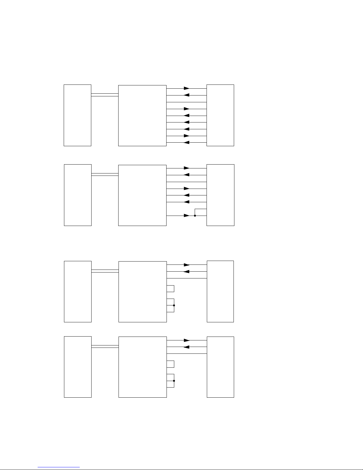
Wiring examples
34211
20mA
RxD +
RxD -
TxD +
TxD -
PC
active / passive
20mA device
Interface Tx loop active, interface Rx loop passive
1
2
3
4
6
7
8
9
Data Out 20mA
Data Out+
Data Out -
Data Out GND
Data In 20mA
Data In+
Data In -
Data In GND
34211
RxD +
RxD -
TxD +
TxD -
PC
active
20mA device
Interface Tx and Rx loop passive
1
2
3
4
6
7
8
9
Data Out 20mA
Data Out+
Data Out -
Data Out GND
Data In 20mA
Data In+
Data In -
Data In GND
20mA
34211
20mA
RxD +
RxD -
TxD +
TxD -
PC
passive
20mA device
Interface Tx and Rx loop active
1
2
3
4
6
7
8
9
Data Out 20mA
Data Out+
Data Out -
Data Out GND
Data In 20mA
Data In+
Data In -
Data In GND
USB USB
USB
USB
USB
USB

56
W&T USB Interfaces
Technical Data
Baud rate: 300..19.200 baud
Data bits: 7 or 8
Stop bits: 1 or 2
Parity: no, even, odd, mark, space
Supported signals: RxD, TxD
Modes: active or passive mode
full and half duplex mode
with or without echo suppression
Galvanic isolation: min. 1kV isolation voltage
ESD rating: up to 15kV per IEC 801-2, Level 4
Supply voltage: 5V DC via USB
Operating current draw: max. 200mA
USB connector: USB type B socket
20mA connector: 9-pin SUB-D plug
Ambient temperature: Storage: -40..+70°C
Operating: 0..+60°C
Housing / Dimensions: Plastic housing for rail mount
according to EN 50022-35,
105 x 75 x 22mm
Weight: approx. 170g
Included: USB <> 20mA Interface
USB cable A-B with ferrite core,
Product CD with driver software

57
W&T
Subject to error and alteration
USB Interfaces
Interface USB <> RS232/RS422/RS485, #38211
The W&T USB-Interface Model 38211 enables bi-directional
connection of computers having a USB port with RS232 and
RS422 devices as well as with RS485 bus systems. In RS232
mode the device supports all signals present on the 9-pin
RS232 interface, in RS422 mode one data and one handshake
signal respectively, and in RS485 mode one data signal in each
direction. The converter is integrated in a plastic housing for
mounting on EN 50022-35 standard rails.
Supply voltage
The Interface requires no additional external power supply,
since it is powered through the USB. The current draw of the
device is max. 200mA.
To reduce the load of the supplying USB host or hub, the
Interface can however be powered by an external 5V power
supply. Suitable power supplies can be obtained from W&T
under article number 11053.
Galvanic isolation and ESD protection
The Interface has galvanic isolation with an isolation voltage of
1kV DC between the USB and the serial side. All signal lines for
the Interface are protected against static discharge for a
voltage of up to 15kV per IEC 801-2, Level 4..

58
W&T USB Interfaces
Integrated overvoltage protection
The permissible voltages which are allowed to affect serial
interfaces in fault situations are limited to rather low values
according to the data sheets of the interface chips used here.
Voltages which exceed these values will inevitably result in
destruction of or damage to the interface components.
To prevent such effects, the USB Interface Model 38211 has
integrated overvoltage protection, which uses protection
diodes to limit the maximum voltages which can occur to
non-harmful values in a variety of applications.
This overvoltage protection of course is limited by the capacity
of the diodes used, which can carry a current of 20A for a brief
time, and cannot replace any major protection which might be
required for long cables used outdoors (e.g. in the mountains).
Wiring configuration
The serial connection on the Interface is configured as a
DB9 plug. The pin configuration can be found in the following
tables:
RS232 mode RS422/RS485 mode
pin# signal function
1 DCD input
2 RxD input
3 TxD output
4 DTR output
5 GND GND
6 DSR input
7 RTS output
8 CTS input
9 RI input
pin# signal function
1 TXD A output
2 RxD A input
3 DTR A output
4 CTS A input
5 GND GND
6 TXD B output
7 RxD B input
8 DTR B output
9 CTS B input

59
W&T
Subject to error and alteration
USB Interfaces
Operating modes
The combined RS232/RS422/485 port on the Interface can be
set to various operating modes using DIL switches inside the
unit, which are described in brief below:
RS232 mode
One data channel in each direction (RxD and TxD) is supported
as well as six handshake channels (RTS, CTS, DSR, DCD, DTR
and RI).
RS422 mode
The Interface supports one data and one handshake channel
(selectable DTR or RTS handshake output) in each direction.
The RS422 transceivers are always active in this mode.
RS485 mode
In all RS485 modes there is one data channel available in each
direction. The operating modes differ only in how the RS485
transceivers are controlled.
RS485 4-wire bus master
In this mode the Master sends requests to the Slaves over a
pair of wires, and the Slaves send their replies to the Master
over another common wire pair. The RS485 drivers and receivers are always active in this mode, whereby the Master can always send and is continuously listening for the Slaves.
RS485 4-wire mode / RS485 2-wire mode with echo
There is one data channel available in each direction. The
RS485 driver chips is automatically activated each time data is
sent and then switched to tristate at the end of data transmission. The receiver channel is always active in this mode.
RS485 2-wire mode without echo
There is one data channel in each direction available. The
RS485 driver is automatically activated each time data is sent
and switched to tristate after the end of data transmission. The
receive channel is deactivated when the driver is on, and on
when the driver is in tristate.

60
W&T USB Interfaces
Display elements
The interface has two green LEDs. The On Line LED indicates
that the interface has a connection to the driver software and
that the software has activated the serial interface circuitry. The
Data LED indicates data activity in both directions.
Terminating
All RS485 modes on the Interface require terminating the bus
system with a termination network which ensures a defined rest
state in the tristate phases of bus operation. The connection of
a bus system to a termination network can be accomplished by
closing DIL switches 6 and 7 inside the Interface.
120
+5V
SW6
SW7
Data In
Data In
330330
Operating mode SW1 SW2 SW3 SW4 SW5
SW6 SW7 SW8
RS232 OFF OFF OFF OFF OFF
OFF
OFF ON
RS422, DTR handshake OFF OFF OFF ON OFF
**
OFF
RS422, RTS handshake OFF OFF OFF OFF ON
**
OFF
RS485, 4-wire bus master OFF OFF OFF OFF OFF
**
OFF
RS485, 4-wire / 2-wire with echo
automatic control
OFF ON OFF OFF OFF
**
OFF
RS485, 2-wire without echo
automatic control
ON ON OFF OFF OFF
**
OFF
Setting the modes
The Interface mode is selected by setting the DIL switch bank
inside the unit. The meaning of the mode switches can be
found in the following table:

61
W&T
Subject to error and alteration
USB Interfaces
Wiring examples
Bus A (-)
Bus B (+)
Bus A (-)
Bus B (+)
RS485 2-wire application
Data Out A
Data Out B
Data In A
Data In B
RS485 interface
1
6
2
7
RS485
device
RS485
device
Data Out A
Data Out B
Data In A
Data In B
RS485 interface
1
6
2
7
RxD A (-)
RxD B (+)
TxD A (-)
TxD B (+)
RxD A (-)
RxD B (+)
TxD A (-)
TxD B (+)
RS485
device
RS485 4-wire bus master application
RS485
device
RxD A (-)
RxD B (+)
TxD A (-)
TxD B (+)
CTS A (-)
CTS B (+)
RTS A (-)
RTS B (+)
RS422
device
RS422 application with hardware handshake
Data Out A
Data Out B
Data In A
Data In B
Handshake Out A
Handshake Out B
Handshake In A
Handshake In B
RS422 interface
1
6
2
7
3
8
4
9
Modem
RS232 application with hardware handshake
DCD
RxD
TxD
DTR
GND
DSR
RTS
CTS
RI
RS232 interface
1
2
3
4
5
6
7
8
9
DCD
RxD
TxD
DTR
GND
DSR
RTS
CTS
RI
8
3
2
20
7
6
4
5
22
38211
PC
USB USB
38211
PC
USB USB
38211
PC
USB USB
38211
PC
USB USB

62
W&T USB Interfaces
Technical Data
Modes: RS232, RS422, RS485 2-/4-wire,
with and without echo
Standard baud rates: 300..115.200 baud
Settable baud rates: Depending on application and
operating system up to 3 Mbaud
Baud rate: 3 MHz/n , n = 1..16383
Data bits: 7 or 8
Stop bits: 1 or 2
Parity: no, even, odd, mark, space
Supported signals: RS232: RxD, TxD, RTS, CTS,
DSR, DCD, DTR, RI
RS422: RxD A/B, TxD A/B,
CTS A/B, DTR A/B (RTS A/B)
RS485: RxD A/B, TxD A/B
RS485 switchover time: 1 bit time for switching from data
sending to receiving
Termination: Switchable termination network for
RS485 mode
Galvanic isolation: min. 1KV isolation voltage between
the interfaces
ESD rating: Up to 15kV per IEC 801-2,Level 4
Supply voltage: 5V DC via USB
Idle current draw: RS232: typ. 70mA
RS422/485: typ. 90mA
Operating current draw: max. 200mA
USB connection: USB TYP B - female
Serial connection: 9-pin SUB-D plug
Ambient temperature: Storage : -40..+70°C
Operating: 0..+60°C
Housing / Dimensions: Plastic housing for DIN rail mount
per EN 50022-35, 105x75x22mm
Weight: approx. 170g
Scope of delivery: Interface USB <> RS232/422/485
USB cable A-B with ferrite ring
Product CD with driver software

63
W&T
Subject to error and alteration
USB Interfaces
USB <> 20mA Interface, #34201
The 34201 Interface permits galvanically isolated, bi-directional connection of active and passive 20mA devices with
computers having an USB port.
This Interface supports one data line in each direction and uses
galvanic isolation between the USB and the 20mA side in all
operating modes. The converter is contained in a plastic
housing for mounting on standardized rails according to EN
50022-35.
Power supply
The supply voltage for the Interface is provided by means of an
integrated switching regulator. This regulator has a variable
input voltage range and allows the Interface to be supplied by
any DC or AC voltage between 12 and 24 volts. The supply
voltage line is polarity reverse protected and is connected using
the plug-in screw terminal provided.
It is unfortunately not possible to supply the Interface from the
USB, since a voltage of at least 12 V is required.
Galvanic isolation and ESD protection
Both ports on the Interface are galvanically isolated to 1kV both
from each other and from the supply voltage. Galvanic
isolation of the signals is accomplished using fast optocouplers; the driver and receiver chips on the USB and 20mA
side are supplied with power by a galvanically isolated DC/DC
converter.
All 20mA signal lines are protected against static discharge up
to a voltage of 15 kV according to IEC 801-2, Level 4.

64
W&T USB Interfaces
Wiring configuration
The 20mA termination of the Interface is implemented as a DB9
plug. The pin assignments for the connector can be found in
the following table as well as on a sticker applied to the unit.
Display elements
The Interface features two LED’s, with the Power LED indicating
correct supply voltage and the Data LED data communication
in both directions.
Modes
The Interface can be used both as an active and a passive 20mA
component. In active mode the Interface provides the loop
current for the respective 20mA loop, whereas in passive mode
the connected device must provide the loop current.
The mode can be selected separately over the external
configuration of the Interface. Examples for configuring the
Interface in active and passive mode can be found in the
following application examples.
pin# signal
1 Data Out 20mA
2 Data Out +
3 Data Out -
4 Data Out GND
5 Half Duplex Control
6 Data In 20mA
7 Data In +
8 Data In -
9 Data In GND

65
W&T
Subject to error and alteration
USB Interfaces
A GND level signal on Pin 5 of the SUB-D connector will place
the module in half-duplex mode whereby an echo of the sent
signals is suppressed.
Wiring examples
34201
20mA
RxD +
RxD -
TxD +
TxD -
PC
active / passive
20mA device
Interface Tx loop active, interface Rx loop passive
1
2
3
4
6
7
8
9
Data Out 20mA
Data Out+
Data Out -
Data Out GND
Data In 20mA
Data In+
Data In -
Data In GND
34201
RxD +
RxD -
TxD +
TxD -
PC
active
20mA device
Interface Tx and Rx loop passive
1
2
3
4
6
7
8
9
Data Out 20mA
Data Out+
Data Out Data Out GND
Data In 20mA
Data In+
Data In -
Data In GND
20mA
34201
20mA
RxD +
RxD -
TxD +
TxD -
PC
passive
20mA device
Interface Tx and Rx loop active
1
2
3
4
6
7
8
9
Data Out 20mA
Data Out+
Data Out Data Out GND
Data In 20mA
Data In+
Data In -
Data In GND
USB USB
USB
USB
USB
USB

66
W&T USB Interfaces
Technical Data
Baud rate: 300..19.200 baud
Data bits: 7 or 8
Stop bits: 1 or 2
Parity: no, even, odd, mark, space
Supported signals: RxD, TxD
Modes: active or passive mode
full and half duplex mode
with or without echo suppression
Galvanic isolation: min. 1kV isolation voltage between
the power supply and Interfaces
ESD rating: up to 15kV per IEC 801-2, Level 4
Supply voltage: 12..24V AC/DC
Operating current draw: approx. 175mA @12V DC
USB connector: USB type B socket
20mA connector: 9-pin SUB-D plug
Ambient temperature: Storage: -40..+70°C
Operating: 0..+60°C
Housing / Dimensions: Plastic housing for rail mount
according to EN 50022-35,
105 x 75 x 22mm
Weight: approx. 100g
Included: USB <> 20mA Interface
USB cable A-B with ferrite core,
Product CD with driver software

67
W&T
Subject to error and alteration
USB Interfaces
USB <> RS422/RS485 Interface, #36201
The 36201 Interface allows galvanically isolated, bi-directional
connection of RS422 and RS485 devices to computers having
an USB port.
The Interface supports one data and one handshake line each
in both directions and provides galvanic isolation between the
USB and the RS422/RS485 side. The converter is contained in a
plastic housing for mounting to standardized rails according
to EN 50022-35.
Power supply
The supply voltage for the Interface is provided by means of an
integrated switching regulator. This regulator has a variable
input voltage range and allows the Interface to be supplied by
any DC or AC voltage between 12 and 24 volts. The supply
voltage line is polarity reverse protected and is connected using
the plug-in screw terminal provided.
It is unfortunately not possible to supply the Interface from the
USB, since a voltage of at least 12 V is required.
Galvanic isolation and ESD protection
Both ports on the Interface are galvanically isolated to 1kV both
from each other and from the supply voltage. Galvanic
isolation of the signals is accomplished using fast optocouplers; the driver and receiver chips on the USB and RS422/
RS485 side are supplied with power by a galvanically isolated
DC/DC converter.
All RS422/RS485 signal lines are protected against static
discharge up to a voltage of 15kV according to IEC 801-2,
Level 4.

68
W&T USB Interfaces
Wiring configuration
The RS422/RS485 termination of the Interface is implemented
as a DB9 plug. The pin assignments for the connector can be
found in the following table as well as on a sticker applied to
the unit.
Display elements
The Interface features two LED’s, with the Power LED indicating
correct supply voltage and the Data LED data communication
in both directions.
Pin# Function
1 data out A (-)
2 data in A (-)
3 handshake out A (-)
4 handshake in A (-)
5 signal GND
6 data out B (+)
7 data in B (+)
8 handshake out B (+)
9 handshake in B (+)

69
W&T
Subject to error and alteration
USB Interfaces
Modes
The RS422/RS485 port of the Interface uses DIL switches to set
one of five operating modes, which are described in brief
below:
RS422, RS485 4-wire bus master
One data and one handshake channel in each direction. The
RS422/RS485 drivers and receivers are always active in this
mode.
RS485 4-wire/ 2-wire with echo, handshake control
One data channel in each direction. The RS485 driver chip is
switched on when DTR = „ON“, whereas DTR = „OFF“ places the
driver in high-impedance state. The receive channel is always
active in this mode.
RS485 2-wire without echo, handshake control
One data channel in each direction. The RS485 driver chip is
switched on when DTR = „ON“, whereas DTR = „OFF“ places the
driver in high-impedance state. The receive channel is deactivated when the driver is turned on, and activated when the
driver is in the high-impedance state.
RS485 4-wire/ 2-wire with echo, automatic control
One data channel in each direction. The RS485 driver chip is
automatically activated whenever data is sent out and placed in
the high-impedance state when data transmission is completed. The receive channel is always active in this mode.
RS485 2-wire without echo, automatic control
One data channel in each direction. The RS485 driver chip is
automatically activated whenever data is sent out and placed in
the high-impedance state when data transmission is completed. The receive channel is deactivated with the driver is turned
on, and activated when the driver is in the high-impedance
state.

70
W&T USB Interfaces
Setting the modes
For the meaning of the DIL switch settings, see the following
table:
Terminating
All RS485 modes require that the bus system be terminated with
a terminating network, which ensures a defined idle state.
The bus system can be connected to a terminating network in
the Interface by closing DIL switches 6 and 7 on the RS422/
RS485 module:
120
+5V
SW6
SW7
Data In
Data In
330330
Operating mode SW1 SW2 SW3 SW4 SW5 SW8
RS422, RS485, 4-wire bus master OFF OFF OFF ON OFF
OFF
RS485, 4-wire / 2-wire with echo,
handshake control
OFF OFF ON ON OFF
OFF
RS485, 4-wire / 2-wire without echo,
handshake control
ON OFF ON ON OFF
OFF
RS485, 4-wire / 2-wire with echo,
automatic control
OFF ON OFF ON OFF
OFF
RS485, 4-wire / 2-wire without echo,
automatic control
ON ON OFF ON OFF
OFF

71
W&T
Subject to error and alteration
USB Interfaces
Wiring examples
RS485
Bus A (-)
Bus B (+)
Bus A (-)
Bus B (+)
PC
36201
RS485
device
RS485
device
RS485 2-wire application
1
6
2
7
DOut A
DOut B
DIn A
DIn B
36201
RS485
RxD A (-)
RxD B (+)
TxD A (-)
TxD B (+)
RxD A (-)
RxD B (+)
TxD A (-)
TxD B (+)
PC
RS485
device
RS485
device
RS485 4-wire bus master application
1
6
2
7
DOut A
DOut B
DIn A
DIn B
1
6
2
7
3
8
4
9
DOut A
DOut B
DIn A
DIn B
HOut A
HOut B
HIn A
HIn B
RxD A (-)
RxD B (+)
TxD A (-)
TxD B (+)
CTS A (-)
CTS B (+)
RTS A (-)
RTS B (+)
RS422
PC
36201
RS422
device
RS422 hardware handshake application
USB USB
USB
USB
USB
USB

72
W&T USB Interfaces
Technical Data
Standard baud rates: 300..115.200 baud
Settable baud rates: Depending on the application and
operating system, up to 3 MBaud
Baud rate: 3 MHz/n , n = 1..16383
Data bits: 7 or 8
Stop bits: 1 or 2
Parity: no, even, odd, mark, space
Supported signals: RxD, TxD, CTS, DTR
Operating modes: RS422
RS485 2/4 wire mode with
automatic control
RS485 2/4 wire mode with
handshake control
Switchover delay: approx. 10µs from send to receive
for RS485 automatic control (can
be factory changed on request)
Termination: Switchable termination network for
RS485 mode
Galvanic isolation: min. 1KV isolation voltage between
the interfaces and between the
power supply and interfaces
ESD rating: up to 15kV per IEC 801-2, Level 4
Supply voltage: 12..24V AC/DC
Operating current draw: approx. 150mA @12V DC
USB connector: USB type B socket
RS422/RS485 connector: 9-pin SUB-D plug
Ambient temperature: Storage: -40..+70°C
Operating: 0..+60°C
Housing / Dimensions: Plastic housing for rail mounting
according to EN 50022-35,
105 x 75 x 22mm
Weight: approx. 100g
Included: USB <> RS422/RS485 Interface
USB cable A-B with ferrite core,
Product CD with driver software

73
W&T
Subject to error and alteration
USB Interfaces
USB <> RS232 Interface , #38201
The 38201 Interface allows galvanically isolated, bi-directional
connection of RS232 devices to computers having an USB port.
The Interface supports all signals present on the 9-pin RS232
port and has galvanic isolation between the USB and RS232
side. The converter is contained in a plastic housing for
mounting to standardized rails according to EN 50022-35.
Power supply
The supply voltage for the Interface is provided by means of an
integrated switching regulator. This regulator has a variable
input voltage range and allows the Interface to be supplied by
any DC or AC voltage between 12 and 24 volts. The supply
voltage line is polarity reverse protected and is connected using
the plug-in screw terminal provided.
It is unfortunately not possible to supply the Interface from the
USB, since a voltage of at least 12 V is required.
Galvanic isolation and ESD protection
Both ports on the Interface are galvanically isolated to 1kV both
from each other and from the supply voltage. Galvanic isolation
of the signals is accomplished using fast opto-couplers; the
driver and receiver chips on the USB and RS232 side are supplied with power by a galvanically isolated DC/DC converter.
All RS232 signal lines are protected against static discharge up
to a voltage of 15kV according to IEC 801-2, Level 4.

74
W&T USB Interfaces
Wiring configuration
The RS232 termination of the Interface is implemented as a DB9
plug. The pin assignments for the connector can be found in
the following table as well as on a sticker applied to the unit.
Display elements
The Interface features two LED’s, with the Power LED indicating
correct supply voltage and the Data LED data communication
in both directions.
Pin# Function Direction
1 DCD input
2 RxD input
3 TxD output
4 DTR output
5 GND GND
6 DSR input
7 RTS output
8 CTS input
9 RI input

75
W&T
Subject to error and alteration
USB Interfaces
Wiring examples
RS232 wiring example with hardware handshake
RS232 wiring example with software handshake
DB25 male DTEDB9 male DTE
TxD
RxD
GND
RTS
CTS
DSR
DCD
DTR
RI
PC
3
2
7
5
4
20
8
6
RxD
TxD
GND
CTS
RTS
DTR
DCD
DSR
38201
3
2
5
7
8
6
1
4
9
USB USB
DTE Device
2
3
7
4
5
6
8
20
22
DB9 male DTE DB25 male DCE
TxD
RxD
GND
RTS
CTS
DSR
DCD
DTR
RI
TxD
RxD
GND
PC
DCE Device
2
3
7
38201
3
2
5
7
8
6
1
4
9
USB USB
DB9 male DTE
DB25 male DTE
TxD
RxD
GND
RTS
CTS
DSR
DCD
DTR
RI
RxD
TxD
GND
PC
DTE Device
3
2
7
38201
3
2
5
7
8
6
1
4
9
USB USB
DB9 male DTE DB25 female DCE
TxD
RxD
GND
RTS
CTS
DSR
DCD
DTR
RI
TxD
RxD
GND
RTS
CTS
DSR
DCD
DTR
RI
PC
DCE Device
38201
3
2
5
7
8
6
1
4
9
USB USB

76
W&T USB Interfaces
Technical Data
Baud rate: 300..115.200 baud
Data bits: 7 or 8
Stop bits: 1 or 2
Parity: no, even, odd, mark, space
Supported signals: RxD, TxD, RTS, CTS,
DSR, DCD, DTR, RI
Galvanic isolation: min. 1kV isolation voltage between
the power supply and Interfaces
ESD rating: up to 15kV per IEC 801-2, Level 4
Supply voltage: 12..24V AC/DC
Operating current draw: approx. 150mA @12V DC
USB connector: USB type B socket
RS232 connector: 9-pin SUB-D plug with DTE pinout
Ambient temperature: Storage: -40..+70°C
Operating: 0..+60°C
Housing / Dimensions: Plastic housing for rail mount
according to EN 50022-35,
105 x 75 x 22mm
Weight: approx. 100g
Included: USB <> RS232 Interface
USB cable A-B with ferrite core,
Product CD with driver software
 Loading...