

Page 1

37
W&T
Serial PCI cards
Subject to error and alteration
Manual
Serial PCI Cards
Models 13011, 13410
13411, 13610
13611, 13812
Version 1.4
W&T
Page 2

38
W&T
Serial PCI cards
© 01/2005 by Wiesemann & Theis GmbH
Subject to errors and changes:
Since we can make mistakes, none of our statements should be
used without checking. Please let us know of any mistakes or
misunderstandings you are aware of, so that we can recognize
and eliminate them quickly.
Perform work on and with W&T products only as described here
and only if you have read and understood the manual fully. Unauthorized use can result in hazards. We are not liable for the
consequences of unauthorized use. When in doubt, check with
us or consult your dealer!
Page 3

39
W&T
Serial PCI cards
Subject to error and alteration
The gradual decline in ISA slots in modern PCs has made it necessary to make the functionality of ISA cards available for the
PCI bus as well.
W&T has responded by creating an entire family of serial PCI
interface cards which meet the needs of industrial automation
through integrated galvanic isolation of the PC ports and the
ability to equip the serial ports of the card with a variety of physical interfaces.
This PCI card family is described on the following pages along
with their technical specifications and wiring examples.
The inherent benefits of PCI with respect to easy installation
and automatic assigning of PC resources stand in contrast to
the fact that these cards are no longer supported by the operating system itself, but rather require driver software.
One exception is Linux, which in kernel version 2.4. and higher
supports the serial W&T PCI cards directly, without additional
driver software.
Current information on the new developments as well as the
newest driver releases can be found in the Internet at
http://www.wut.de or in the e-mail updates provided to members of the W&T Interface Club. Subscriptions to the Interface
Club can requested from the W&T homepage.
Page 4

40
W&T
Serial PCI cards
Contents
Inhalt
Serial Low Profile PCI Cards
General Characteristics ....................................................... 41
1x 20mA, 1kV isolated, #13410 .......................................... 45
1x RS232 / RS422 / RS485, 1kV isolated, #13610 ................. 49
Serial Standard PCI Cards
General Characteristics ....................................................... 55
Base board for interface modules, 1kV isolated, #13011 ........ 59
2x 20mA, 1kV isolated, #13411 .......................................... 61
2x RS422/RS485, 1kV isolated, #13611 .............................. 65
2x RS232, 1kV isolated, #13812 .......................................... 71
Page 5
41
W&T
Serial PCI cards
Subject to error and alteration
Low Profile PCI cards: General characteristics
Function
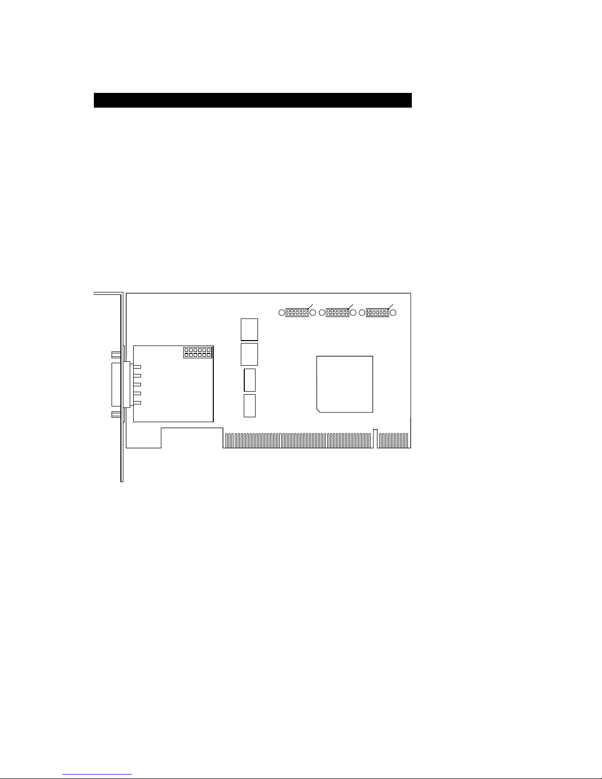
All serial Low Profile PCI cards add the functionality of maximum four additional serial ports to your PC. One of these ports
(Port 1) is integrated on the interface card, whereas three additional, optional ports (ports 2 through 4) are connected to the
circuit board through ribbon cable. These optional ports are
configured on the PCI card as serial TTL interfaces which can
be converted into any serial standard interface (RS232, RS422,
RS485 or 20mA) using W&T Interface Modules.
Adapting to the physical housing requirements
The serial interface cards are supplied with a short slot bracket
which enables installation in Low Profile PCI systems. A longer
slot bracket is provided for attaching the cards in standard PCI
systems; this is attached to the circuit board in place of the
short slot bracket.
To make the switch, remove the two threaded pins on the SUBD plug, remove the slot bracket and attach the new bracket to
the SUB-D plug using the threaded pins.
Port 2
Port 3
Port 4
Pin 1
Pin 1
Pin 1
Port 1
Page 6

42
W&T
Serial PCI cards
Galvanic isolation and ESD protection
Port 1 on all W&T Low Profile PCI interface cards is galvanically
isolated from the PC with an isolation voltage of at least 1kV
DC, whereas the optional ports 2 through 4 have no galvanic
isolation from the PC.
Galvanic isolation of the signals is implemented using fast
opto-couplers; driver and receiver chips are powered by a galvanically isolated DC/DC converter. Please note that the shielding for the port connectors has a direct connection to the
chassis ground of the PC using the metallic slot bracket.
The signal lines for the serial ports are protected against static
discharge for a voltage of up to 15kV per IEC 801-2, Level 4.
Driver and software installation
All the serial PCI interface cards are accessible under the various operating systems only using special drivers. These drivers are subject to continuous improvement both with respect
to their technical features and the number and type of supported operating systems.
For this reason W&T makes the current drivers and software installation manuals available on the data sheet pages for the PCI
cards in the Internet under http://www.wut.de.
Implementing optional ports 2 through 4
As an option all serial Low Profile interface cards are able to
also provide three additional serial ports in addition to the port
integrated on the card. These ports are configured on the card
as serial TTL interfaces which can be converted into the desired interface type by using interface modules.
It must be noted however that the optional ports 2 through 4
are not galvanically isolated from each other or from the PC, so
that these ports may be used only for connecting peripherals
Page 7

43
W&T
Serial PCI cards
Subject to error and alteration
where no ground potential differences can be expected. This
would include any peripherals which are located in the direct
vicinity of the PC and thus are powered from the same sub-division as well as peripherals which are inherently potential-free.
This generally applies to all devices which are powered from the
interface or by a plug-in power supply. In all other cases external galvanic isolation must be provided.
The additional interface modules are connected to the interface
card using 2mm ribbon cable and attached by means of a slot
bracket in the PC housing. Both components can be obtained
as a special accessory from W&T under article number 13014.
The ribbon cable connectors can be affixed to the interface card
as needed using standard cable ties.
1
Page 8

44
W&T
Serial PCI cards
Important notes
The serial W&T PCI cards may be equipped only with the 18x1x
series interface modules (e.g. 18811, 18813, 18611, 18411,
etc.) which have a supply voltage of 5V DC.
The use of 3.3V modules in the18x3x series (e.g. 18831,
18833, 18631, etc. ) will result in destruction of the interface
modules and/or the PCI card.
When installing you must ensure that the arrangement of the
ribbon cable and the interface modules corresponds to the drawing below. Otherwise the modules and/or the interface card
may be destroyed.
1
Port 3
Port 4
Pin 1
Pin 1
Interface
Module
Port 2
Interface
Module
Port 3
Pin 1
Optional fixing of
connectors by
cable straps
Pin 1
Pin 1
Interface
Module
Port 4
Pin 1
Port 2
Red Pin 1
Marking
Red Pin 1
Marking
Red Pin 1
Marking
Page 9

45
W&T
Serial PCI cards
Subject to error and alteration
Low Profile PCI card 1x 20mA, #13410
Function
The W&T PC card model 13410 provides a serial 20mA interface with galvanic isolation of 1kV DC on port 1. Ports 2 through 4 may also be used for any three, non-galvanically isolated serial ports.
Wiring configuration
The 20mA connection for the PC card is implemented as a DB9
plug. The connector pin assignments are shown in the following table:
Applications
A ground level signal on Pin 5 of the SUB-D connector can be
used to bring the 20mA interface into half-duplex mode, in
which there is echo suppression of the sent signals.
The PC card can be used as either an active or passive 20mA
component. In active mode the card provides the loop current
for the respective 20mA loop, whereas in passive mode the
connected device itself must provide the loop current.
pin# function
1 Data Out 20 mA
2 Data Out +
3 Data Out -
4 Data Out GND
5 Halfduplex control
6 Data In 20 mA
7 Data In +
8 Data In -
9 Data In GND
Page 10
46
W&T
Serial PCI cards
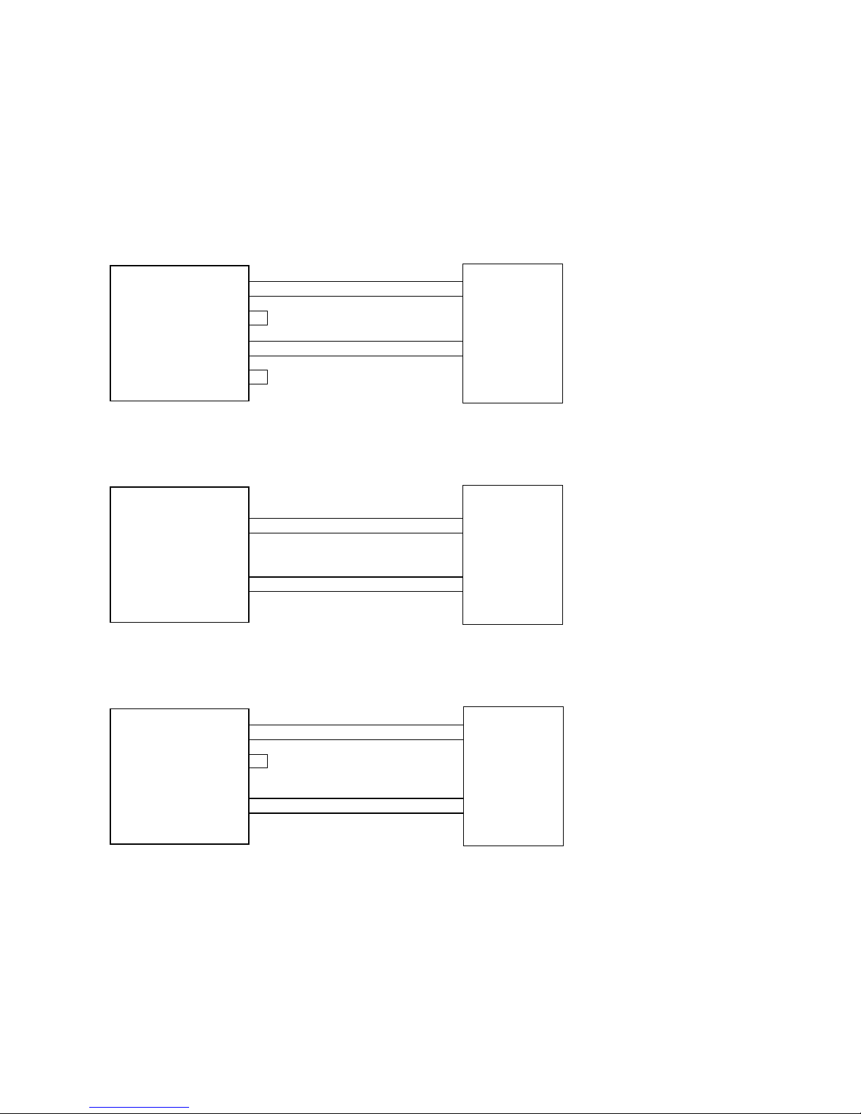
The operating mode can be set separately for both loops using
the external wiring of the card. Examples for wiring the PC card
in active/passive mode can be seen in the following drawings:
RxD +
RxD -
TxD +
TxD -
Active / Passive
20mA device
Active Tx and Passive Rx Current Loop Application
20mA Interface
1
2
3
4
6
7
8
9
Data Out 20mA
Data Out+
Data Out -
Data Out GND
Data In 20mA
Data In+
Data In -
Data In GND
RxD +
RxD -
TxD +
TxD -
Active
20mA Device
Passive Tx and Passive Rx Current Loop Application
20mA Interface
1
2
3
4
6
7
8
9
Data Out 20mA
Data Out+
Data Out -
Data Out GND
Data In 20mA
Data In+
Data In -
Data In GND
RxD +
RxD -
TxD +
TxD -
Passive
20mA Device
Active Tx and Active Rx Current Loop Application
20mA Interface
1
2
3
4
6
7
8
9
Data Out 20mA
Data Out+
Data Out -
Data Out GND
Data In 20mA
Data In+
Data In -
Data In GND
PCI card
13410
PCI card
13410
PCI card
13410
Page 11

47
W&T
Serial PCI cards
Subject to error and alteration
Technical Data
System bus: 32-bit bus / 33MHz
PCI standard: PCI2.2 / signal voltage: 5V
Serial ports: One galvanically isolated 20mA-port
Three non-isolated TTL-ports
Galvanic isolation: port 1: min. 1kV DC
port 2..4: No isolation
Modes: Active and passive mode
Full- and half-duplex mode
UART: 16950 with 128 bytes FIFO
Base addresses: automatic configuration
Interrupts: automatic configuration
Baud rate: 50..57.600 baud
Data format: any
Signals: RxD+, RxD-, TxD+, TxD-
Serial connections: 1x 9-pin. SUB-D plug
3x 12-pin. 2mm PCB plug
Supply voltage: +5V, typ. 180mA
Dimensions: 119.9 x 63.5 mm
Weight: approx. 110 g
Scope of delivery: Low Profile PCI card 1x 20mA
Standare slot bracket
Driver CD
Page 12

48
W&T
Serial PCI cards
Page 13

49
W&T
Serial PCI cards
Subject to error and alteration
Low Profile PCI card 1x RS232/RS422/RS485, #13610
Function
The W&T PC card model 13610 provides on port 1 a switchable
serial RS232/RS422/RS485 interface with 1kV DC galvanic isolation. Ports 2 through 4 can also be used for any three nongalvanically isolated serial interfaces.
Wiring configuration
The serial connection of the Low Profile PCI card is configured
as a DB9 plug. The connector pin assignments are shown in
the following table:
RS232 mode RS422/RS485 mode
Modes
The combined RS232/RS422/485 interface of the PCI card can
be set to various operating modes using the DIL switches located near the serial connector as described briefly below:
RS232 mode
This mode provides one data channel each (RxD and TxD) in
each direction as well as six handshake channels (RTS, CTS,
DSR, DCD, DTR and RI).
pin# signal function
1 DCD input
2 RxD input
3 TxD output
4 DTR output
5 GND GND
6 DSR input
7 RTS output
8 CTS input
9 RI input
pin# signal function
1 TXD A output
2 RxD A input
3 DTR A output
4 CTS A input
5 GND GND
6 TXD B output
7 RxD B input
8 DTR B output
9 CTS B input
Page 14

50
W&T
Serial PCI cards
RS422 mode
The PCI card supports one data and one handshake channel
each (selectable DTR or RTS handshake output) in each direction. The RS422 sender and receiver chips are always active.
RS485 mode
In all RS485 modes there is one data channel available in each
direction. The operating modes differ only in how the RS485
driver and receiver chips are controlled.
RS485 4-wire bus master
In this mode the Master uses a wire pair to send requests to the
Slaves, which send their replies to the Master on an additional
common wire pair. The RS485 drivers and receivers are always
active, whereby the Master can always send and is continuously listening for the Slaves.
RS485 4-wire mode / RS485 2-wire mode with echo,
handshake control
One data channel in each direction is available. The RS485 driver chip is turned „ON“ with RTS or DTR, whereas RTS or DTR =
„OFF“ switches the driver to tristate. The receive channel is always active in this mode.
RS485 2-wire mode without echo, with handshake control
One data channel in each direction is available. The RS485 driver chip is turned „ON“ with RTS or DTR, whereas RTS or DTR =
„OFF“ turns the driver into tristate. The receive channel is deactivated when the driver is turned on, and the channel is on when
the driver is in tristate.
Page 15

51
W&T
Serial PCI cards
Subject to error and alteration
RS485 4-wire mode / RS485 2-wire mode with echo,
automatic control
One data channel in each direction is available. The RS485 driver chip is automatically activated for each data transmission
and reset to tristate after data output is finished. The receive
channel is always active in this mode.
RS485 2-wire mode without echo, automatic control
One data channel in each direction is available. The RS485 driver chip is automatically activated for each data transmission
and reset to tristate after data output is finished. The receive
channel is deactivated when the driver is turned on, and the
channel is on when the driver is in tristate.
The DIL switch mode settings are shown in the following table:
Operating mode SW1 SW2 SW3 SW4 SW5 SW6 SW7 SW8
RS232 OFF OFF OFF OFF OFF OFF OFF ON
RS422, RS485, 4-wire bus master
DTR handshake
OFF OFF OFF ON OFF
**
OFF
RS422, RS485, 4-wire bus master
RTS handshake
OFF OFF OFF OFF ON
**
OFF
RS485, 4-wire / 2-wire with echo
DTR control
OFF OFF ON ON OFF
**
OFF
RS485, 2-wire without echo
DTR control
ON OFF ON ON OFF
**
OFF
RS485, 4-wire / 2-wire with echo
RTS control
OFF OFF ON OFF ON
**
OFF
RS485, 2-Draht without echo
RTS control
ON OFF ON OFF ON
**
OFF
RS485, 4-wire / 2-wire with echo
automatic control
OFF ON OFF ON OFF
**
OFF
RS485, 2-wire without echo
automatic control
ON ON OFF ON O FF
**
OFF
Page 16

52
W&T
Serial PCI cards
Terminating
All RS485 modes require terminating the bus system with a termination network which ensures a defined rest state in the tristate phases of bus operation. The bus system can be connected
to a termination network on the PC card by closing DIL switches 6 and 7:
+5V
SW6
SW7
Data In B
Data In A
Page 17

53
W&T
Serial PCI cards
Subject to error and alteration
Bus A (-)
Bus B (+)
Bus A (-)
Bus B (+)
RS485 2-wire application
Data Out A
Data Out B
Data In A
Data In B
RS485 interface
1
6
2
7
RS485
device
RS485
device
Data Out A
Data Out B
Data In A
Data In B
RS485 interface
1
6
2
7
RxD A (-)
RxD B (+)
TxD A (-)
TxD B (+)
RxD A (-)
RxD B (+)
TxD A (-)
TxD B (+)
RS485
device
RS485 4-wire bus master application
RS485
device
RxD A (-)
RxD B (+)
TxD A (-)
TxD B (+)
CTS A (-)
CTS B (+)
RTS A (-)
RTS B (+)
RS422
device
RS422 application with hardware handshake
Data Out A
Data Out B
Data In A
Data In B
Handshake Out A
Handshake Out B
Handshake In A
Handshake In B
RS422 interface
1
6
2
7
3
8
4
9
Modem
RS232 application with hardware handshake
DCD
RxD
TxD
DTR
GND
DSR
RTS
CTS
RI
RS232 interface
PCI card
13610
1
2
3
4
5
6
7
8
9
DCD
RxD
TxD
DTR
GND
DSR
RTS
CTS
RI
8
3
2
20
7
6
4
5
22
PCI card
13610
PCI card
13610
PCI card
13610
Applications
Page 18

54
W&T
Serial PCI cards
Technical Data
System bus: 32-bit bus / 33MHz
PCI standard: PCI2.2 / signal voltage: 5V
Serial ports: One galvanically isolated, selectable
RS232-/RS422-/RS485-port
Three non-isolated TTL-ports
Galvanic isolation: port 1: min. 1kV DC
port 2..4: No isolation
Modes: RS232
RS422
RS485 handshake control
RS485 automatic control
UART: 16950 with 128 bytes FIFO
Base addresses: automatic configuration
Interrupts: automatic configuration
Baud rate: RS232: 50..230.400 baud
RS422/RS485: 50..460.800 baud
Data format: any
Signals: RS232 mode:
RxD, TxD, RTS, CTS, DSR, DTR, DCD, RI
RS422/RS485 mode:
RxD A/B, TxD A/B, CTS A/B, DTR A/B
Serial connections: 1x 9-pin. SUB-D plug
3x 12-pin. 2mm PCB plug
Supply voltage: +5V, typ. 150mA
Dimensions: 119.9 x 63.5 mm
Weight: approx. 110 g
Scope of delivery: Low Profile PCI card
1x RS232/RS422/RS485
Standare slot bracket
Driver CD
Page 19

55
W&T
Serial PCI cards
Subject to error and alteration
Standard PCI cards: Common characteristics
Function
All W&T serial interface cards for PCI bus systems add the functionality of maximum four additional serial ports to your PC.
Two of these ports (port 1 and port 2) are integrated on the
interface card, whereas two additional, optional ports (ports 3
and 4) are connected to the circuit board through ribbon cable.
These 2 optional ports are configured on the PCI card as serial
TTL interfaces which can be converted into any serial standard
interface (RS232, RS422, RS485 or 20mA) using W&T Interface
Modules.
Port 1
Port 2
Port 3
Port 4
Pin 1
Pin 2
Page 20

56
W&T
Serial PCI cards
Galvanic isolation and ESD protection
Ports 1 and 2 on all W&T PCI interface cards are galvanically
isolated from each other and from the PC with an isolation voltage of at least 1kV DC, whereas the optional ports 3 and 4 have
no galvanic isolation from the PC.
Galvanic isolation of the signals is implemented using fast
opto-couplers; driver and receiver chips are powerd by a galvanically isolated DC/DC converter. Please note that the shielding
for the port connectors has a direct connection to the chassis
ground of the PC using the metallic slot bracket.
The signal lines for the serial ports are protected against static
discharge for a voltage of up to 15kV per IEC 801-2, Level 4.
Driver and software installation
All the serial PCI interface cards are accessible under the various operating systems only using special drivers. These drivers are subject to continuous improvement both with respect
to their technical features and the number and type of supported operating systems.
For this reason W&T makes the current drivers and software installation manuals available on the data sheet pages for the PCI
cards in the Internet under http://www.wut.de.
Implementing optional ports 3 and 4
As an option all serial interface cards are able to also provide
two additional serial ports (ports 3 and 4) in addition to the
two ports integrated on the card. These ports are configured
on the card as serial TTL interfaces which can be converted into
the desired interface type by using interface modules.
Page 21

57
W&T
Serial PCI cards
Subject to error and alteration
It must be noted however that the optional ports 3 and 4 are
not galvanically isolated from each other or from the PC, so that
these ports may be used only for connecting peripherals where
no ground potential differences can be expected. This would
include any peripherals which are located in the direct vicinity
of the PC and thus are powered from the same sub-division as
well as peripherals which are inherently potential-free. This generally applies to all devices which are powered from the interface or by a plug-in power supply. In all other cases external
galvanic isolation must be provided.
The additional interface modules are connected to the interface
card using 2mm ribbon cable and attached by means of a slot
bracket in the PC housing. Both components can be obtained
as a special accessory from W&T under article number 13013.
The ribbon cable connectors can be affixed to the interface card
as needed using standard cable ties.
1
Page 22

58
W&T
Serial PCI cards
Important notes
The serial W&T PCI cards may be equipped only with the 18x1x
series interface modules (e.g. 18811, 18813, 18611, 18411,
etc.) which have a supply voltage of 5V DC.
The use of 3.3V modules in the18x3x series (e.g. 18831,
18833, 18631, etc. ) will result in destruction of the interface
modules and/or the PCI card.
When installing you must ensure that the arrangement of the
ribbon cable and the interface modules corresponds to the drawing below. Otherwise the modules and/or the interface card
may be destroyed.
1
Port 3
Port 4
Pin 1
Pin 1
Interface
Module
Port 4
Interface
Module
Port 3
Pin 1
Red Pin 1
Marking
Red Pin 1
Marking
Pin 1
Page 23

59
W&T
Serial PCI cards
Subject to error and alteration
Function
The serial W&T module base board 13011 together with W&T
interface modules provides two independent serial interfaces
with galvanic isolation of 1kV DC as well as two serial interfaces
without galvanic isolation. Integration of the interface-specific
components on the cards in the form of interchangeable interface modules provides for an optional mixed configuration of
the cards with different interface types. This means for example you can easily implement an RS232 interface for connecting
a mouse and a 20mA interface for connecting a controller on a
single card.
Wiring configuration
The serial TTL interface on the base board is implemented as a
12-pin PCB connector. The connector pin assignments are
shown in the following table:
Pin 1 of the connector is indicated by a rectangular soldering
pad.
PCI card base board for Interface-Modules, #13011
pin# signal function
1 5V power supply
2 RI input
3 RxD input
4 TxD output
5 n.c. n.c.
6 CTS input
7 DTR output
8 DSR input
9 RTS output
10 DCD input
11 12V power supply
12 GND signal ground
Page 24

60
W&T
Serial PCI cards
Technical Data
System bus: 32-bit bus / 33MHz
PCI standard: PCI2.2 / signal voltage: 5V
Serial ports: Two galvanically isolated TTL ports
Two non-isolated TTL ports
Note: The card can be configured with
modules of various interface types
Galvanic isolation: port 1,2: min. 1kV DC
port 3,4: No isolation
UART: 16950 with 128 bytes FIFO
Base addresses: automatic configuration
Interrupts: automatic configuration
Baud rate: 50..460.800 baud
Data format: any
Signals: RxD, TxD, RTS, CTS, DSR, DCD, DTR, RI
Serial connections: 4x 12-pin. 2mm PCB plug
Supply voltage: +5V, +12V, depending on current draw
of the modules used
Dimensions: 120 x 106 mm
Weight: approx. 110 g
Scope of delivery: PCI card base board
Driver CD
Page 25

61
W&T
Serial PCI cards
Subject to error and alteration
PCI card 2x 20mA, #13411
Function
The W&T PC card model 13411 provides on port 1 and port 2
two independent serial 20mA interfaces with galvanic isolation
of 1kV DC. Ports 3 and 4 can be used also for any two nongalvanically isolated serial interfaces.
Wiring configuration
The 20mA connections on the PC card are implemented as DB9
plugs. The connector pin assignments are shown in the following table:
Applications
A ground level on Pin 5 of the SUB-D connector places the
20mA interface in half-duplex mode in which there is echo suppression of the sent signals.
The PC card can be used as either an active or passive 20mA
component. In active mode the card provides the loop current
for the respective 20mA loop, whereas in passive mode the
connected device itself must provide the loop current.
pin# function
1 Data Out 20 mA
2 Data Out +
3 Data Out -
4 Data Out GND
5 Halfduplex control
6 Data In 20 mA
7 Data In +
8 Data In -
9 Data In GND
Page 26

62
W&T
Serial PCI cards
The mode can be set independently for both loops using the
external wiring of the card. Examples for wiring the PC card in
active/passive mode are shown in the following drawings:
RxD +
RxD -
TxD +
TxD -
Active / Passive
20mA device
Active Tx and Passive Rx Current Loop Application
20mA Interface
PC with 13411
1
2
3
4
6
7
8
9
Data Out 20mA
Data Out+
Data Out -
Data Out GND
Data In 20mA
Data In+
Data In -
Data In GND
RxD +
RxD -
TxD +
TxD -
Active
20mA Device
Passive Tx and Passive Rx Current Loop Application
20mA Interface
PC with 13411
1
2
3
4
6
7
8
9
Data Out 20mA
Data Out+
Data Out -
Data Out GND
Data In 20mA
Data In+
Data In -
Data In GND
RxD +
RxD -
TxD +
TxD -
Passive
20mA Device
Active Tx and Active Rx Current Loop Application
20mA Interface
PC with 13411
1
2
3
4
6
7
8
9
Data Out 20mA
Data Out+
Data Out -
Data Out GND
Data In 20mA
Data In+
Data In -
Data In GND
Page 27

63
W&T
Serial PCI cards
Subject to error and alteration
Technical Data
System bus: 32-bit bus / 33MHz
PCI standard: PCI2.2 / signal voltage: 5V
Serial ports: Two galvanically isolated 20mA ports
Two non-isolated TTL ports
Galvanic isolation: port 1,2: min. 1kV DC
port 3,4: No isolation
Modes: Active and passive mode
Full- and half-duplex mode
UART: 16950 with 128 bytes FIFO
Base addresses: automatic configuration
Interrupts: automatic configuration
Baud rate: 50..57.600 baud
Data format: any
Signals: RxD+, RxD-, TxD+, TxD-
Serial connections: 2x 9-pin. SUB-D plug
2x 12-pin 2mm PCB plug
Supply voltage: +5V, typ. 200mA, +12V, typ. 100mA
Dimensions: 120 x 106 mm
Weight: approx. 110 g
Scope of delivery: PCI card 2x 20mA
Driver CD
Page 28

64
W&T
Serial PCI cards
Page 29

65
W&T
Serial PCI cards
Subject to error and alteration
PCI card 2x RS422/RS485, #13611
Function
The W&T PC card model 13611 provides on port 1 and port 2
two independent serial RS422/RS485 interfaces with galvanic
isolation of 1kV DC. Ports 3 and 4 can be used also for any two
non-galvanically isolated serial interfaces.
Wiring configuration
The RS422/RS485 connections on the PC card are implemented as DB9 connectors. The connector pin assignments are
shown in the following table:
Modes
The RS422/485 interface of the PCI card can be set to various
operating modes using the DIL switches located near the serial
connector as described briefly below:
pin# function
1 Data Out A (-)
2 Data in A (-)
3 Handshake Out A (-)
4 Handshake In A (-)
5 Signal GND
6 Data Out B (+)
7 Data In B (+)
8 Handshake Out B (+)
9 Handshake In B (+)
Page 30

66
W&T
Serial PCI cards
RS422, RS485 4-wire-Bus-Master
One data and one handshake channel each in each direction is
available. The RS422/RS485 driver and receiver chips are always
active in this mode.
RS485 4-wire mode / RS485 2-wire mode with echo,
handshake control
One data channel in each direction is available. The RS485 driver chip is turned „ON“ with RTS or DTR, whereas RTS or DTR =
„OFF“ turns the driver into tristate. The receive channel is always active in this mode.
RS485 2-wire mode without echo, handshake control
One data channel in each direction is available. The RS485 driver chip is turned „ON“ with RTS or DTR, whereas RTS or DTR =
„OFF“ turns the driver into tristate. The receive channel is deactivated when the driver is turned on and the channel is on when
the driver is in tristate.
RS485 4-wire mode / RS485 2-wire mode with echo,
automatic control
One data channel in each direction is available. The RS485 driver chip is automatically activated for each data transmission
and reset to tristate after data output is finished. The receive
channel is always active in this mode.
RS485 2-wire mode without echo, automatic control
One data channel in each direction is available. The RS485 driver chip is automatically activated for each data transmission
and reset to tristate after data output is finished. The receive
channel is deactivated when the driver is turned on, and the
channel is turned on when the driver is in tristate.
Page 31

67
W&T
Serial PCI cards
Subject to error and alteration
The DIL switch mode settings are shown in the following table:
Terminating
All RS485 modes require terminating the bus system with a termination network which ensures a defined rest state in the tristate phases of bus operation. The bus system can be connected
to a termination network on the PC card by closing DIL switches 6 and 7:
+5V
SW6
SW7
Data In B
Data In A
operating mode SW1 SW2 SW3 SW4 SW5
RS422, RS485, 4 wire bus master, DTR handshake OFF OFF OFF ON OFF
RS422, RS485, 4 wire bus master, RTS handshake OFF OFF OFF OFF ON
RS485, 4 wire / 2-wire with echo, DTR control OFF OFF ON ON OFF
RS485, 2-wire without echo, DTR control ON OFF ON ON OFF
RS485, 4 wire / 2-wire with echo, RTS control OFF OFF ON OFF ON
RS485, 2-wire without echo, RTS control ON OFF ON OFF ON
RS485, 4 wire / 2-wire with echo, automatic control OFF ON OFF ON OFF
RS485, 2-wire without echo, automatic control ON ON OFF ON OFF
Page 32

68
W&T
Serial PCI cards
RxD A (-)
RxD B (+)
TxD A (-)
TxD B (+)
CTS A (-)
CTS B (+)
RTS A (-)
RTS B (+)
RS422
Device
RS422 Hardware Handshake Application
Data Out A
Data Out B
Data In A
Data In B
Handshake Out A
Handshake Out B
Handshake In A
Handshake In B
RS422/485 Interface
PC with 13611
1
6
2
7
3
8
4
9
Data Out A
Data Out B
Data In A
Data In B
Handshake Out A
Handshake Out B
Handshake In A
Handshake In B
RS422/485 Interface
PC with 13611
1
6
2
7
3
8
4
9
RxD A (-)
RxD B (+)
TxD A (-)
TxD B (+)
RxD A (-)
RxD B (+)
TxD A (-)
TxD B (+)
RS485
Device
RS485
Device
RS485 4 Wire Bus Master Application
RS485 2 Wire Application
Data Out A
Data Out B
Data In A
Data In B
Handshake Out A
Handshake Out B
Handshake In A
Handshake In B
RS422/485 Interface
PC with 13611
1
6
2
7
3
8
4
9
Bus A (-)
Bus B (+)
RS485
Device
Bus A (-)
Bus B (+)
RS485
Device
Applications
Page 33

69
W&T
Serial PCI cards
Subject to error and alteration
Technical Data
System bus: 32-bit bus / 33MHz
PCI standard: PCI2.2 / signal voltage: 5V
Serial ports: Two galvanically isolated
RS422-/RS485 ports
Two non-isolated TTL ports
Galvanic isolation: port 1,2: min. 1kV DC
port 3,4: no isolation
Modes: RS422
RS485 handshake control
RS485 automatic control
UART: 16950 with 128 bytes FIFO
Base addresses: automatic configuration
Interrupts: automatic configuration
Baud rate: 50..460.800 baud
Data format: any
Signals: RxD A/B, TxD A/B, CTS A/B, DTR A/B
Serial connections: 2x 9-pin. SUB-D plug
2x 12-pin. 2mm PCB plug
Supply voltage: +5V, typ. 200mA, +12V, typ. 100mA
Dimensions: 120 x 106 mm
Weight: approx. 110 g
Scope of delivery: PCI card 2x RS422/RS485
Driver CD
Page 34

70
W&T
Serial PCI cards
Page 35

71
W&T
Serial PCI cards
Subject to error and alteration
PCI card 2x RS232, #13812
Function
The W&T PC card model 13812 provides on port 1 and port 2
two independent serial RS232 interfaces with galvanic isolation
of 1kV DC. ports 3 and 4 can be used also for any two nongalvanically isolated serial interfaces.
Wiring configuration
The RS232 connections on the PC card are implemented as DB9
plugs with standard PC pin assignments. The connector pin assignments are shown in the following table:
pin# function
1 DCD
2 RxD
3 TxD
4 DTR
5 GND
6 DSR
7 RTS
8 CTS
9RI
Page 36

72
W&T
Serial PCI cards
Technical Data
System bus: 32-bit bus / 33MHz
PCI standard: PCI2.2 / signal voltage: 5V
Serial ports: Two galvanically isolated RS232-ports
Two non-isolated TTL ports
Galvanic isolation: port 1,2: min. 1kV DC
port 3,4: No isolation
UART: 16950 with 128 bytes FIFO
Base addresses: automatic configuration
Interrupts: automatic configuration
Baud rate: 50..230.400 baud
Data format: any
Signals: RxD, TxD, RTS, CTS, DSR, DCD, DTR, RI
Serial connections: 2x 9-pin. SUB-D plug
2x 12-pin. 2mm PCB plug
Supply voltage: +5V, typ. 200mA, +12V, typ. 100mA
Dimensions: 120 x 106 mm
Weight: approx. 110 g
Scope of delivery: PCI card 2x RS232, 1kV isolated
Driver CD
 Loading...