

TReX User Manual v2.14 Firmware
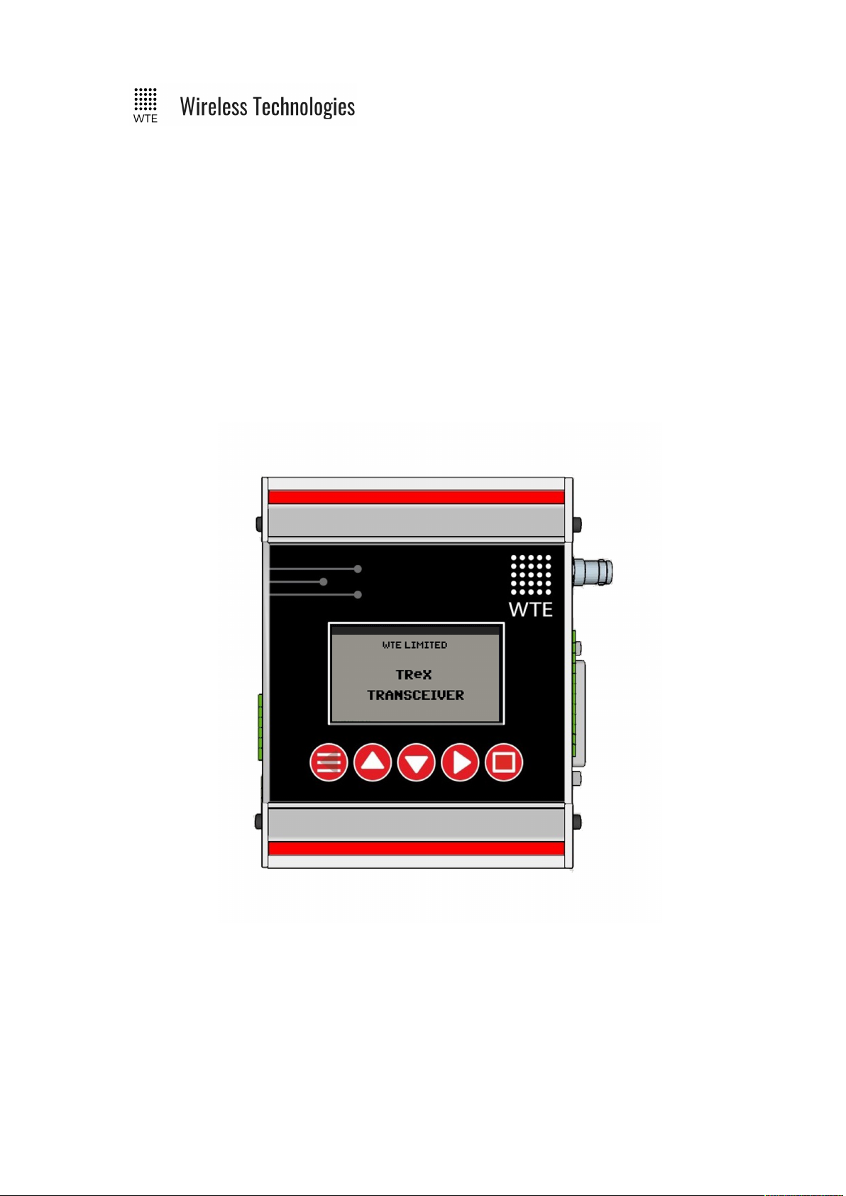
WTE TReX
TELEMETRY, DATA AND PAGING I/O
TRANSCEIVER
User Manual
© WTE Limited, 2018 – Christchurch New Zealand Page 1 of 158

TReX User Manual v2.14 Firmware
Table of Contents
Introduction...............................................5
TReX Features........................................5
TReX Versions........................................6
Safety Information.....................................8
Operation..................................................12
Buttons......................................................13
MENU/BACK:.....................................13
UP:........................................................13
DOWN:.................................................13
RIGHT:.................................................13
ENTER:................................................13
Main Screens............................................14
IO Screens.............................................15
TX Screens............................................17
RX Screens...........................................19
Site Configuration Tools..........................21
Spectrum Analyser................................21
Demodulated Signal Viewer.................22
Two-Way Paging......................................23
Configuration Methods...........................24
Front Panel Menu Configuration..........25
Web Browser Configuration.................27
Serial Command Configuration............29
MENU Configuration..............................31
SYSTEM Menu....................................33
TEST Sub Menu...................................36
FACTORY Sub Menu...........................37
TIME Sub Menu...................................38
SPECTRUM Menu...............................39
RX Menu...............................................41
FILTERS..........................................43
Protocol Menu.......................................46
TCP-IP Menu........................................47
Telemetry Menu....................................49
SERIAL LINK Menu............................51
STORE FWD Menu..............................52
Inputs Menu..........................................53
ADC CAL Sub-Menu...........................54
Input Config Sub-Menu...................56
Outputs Menu.......................................59
Output Config Sub-Menu.................61
DAC CAL Sub-Menu.......................62
Serial Command Configuration.............64
Main Commands...................................64
*REBOOT........................................64
*CONFIG.........................................64
*SAVE..............................................64
*LIST...............................................64
*DEFAULTS....................................64
*RSSI...............................................65
*USERPASS....................................65
*IO....................................................65
*TEMP.............................................66
*PWR...............................................66
*VER................................................66
*BYPASS.........................................66
*LAB................................................67
Transmit Commands.............................68
*TX_FREQ......................................68
*TX_PROTO...................................68
*TX_BAUD.....................................68
*TX_MODE.....................................68
*TX_LEVEL....................................69
*TX_CAP.........................................69
*TX_PERIODIC..............................69
*TX_PREAMBLE...........................69
*TX_LEAD......................................70
Receive Commands..............................71
*RX_ENABLE................................71
*RX_FREQ......................................71
*RX_BAUD.....................................71
*RX_PROTO...................................71
*RX_MODE....................................71
*RX_RANGE..................................72
*RX_BUSY......................................72
Store Forward Commands....................73
*STORE_FWD................................73
Input Commands...................................74
*IN_CONFIG_L..............................74
*IN_CONFIG_H..............................74
*IN_MSG_L....................................75
*IN_MSG_H....................................75
*IN_ANALOG.................................75
Output Commands................................77
*OUT_CONFIG...............................77
*UNIT_ID........................................77
System Commands...............................78
*TREX_LANG................................78
*TREX_BACKLIGHT....................78
*TREX_SOUND..............................78
*TREX_RS232_BAUD...................78
*TREX_RS422_BAUD...................79
© WTE Limited, 2018 – Christchurch New Zealand Page 2 of 158

TReX User Manual v2.14 Firmware
*TREX_ALERT_OUT....................79
*TREX_ALERT...............................79
*TREX_FILTERS............................79
*TREX_TELEMETRY....................80
*TREX_SCREEN............................80
*TREX_PIN.....................................80
*TREX_AN_CAL............................81
*TREX_MISMATCH......................81
TCP-IP Commands...............................83
*IP_ENABLE..................................83
*IP_HOST........................................83
*IP_ADD.........................................83
*IP_PORT........................................83
*IP_MASK.......................................84
*IP_GATE........................................84
*IP_DNS..........................................84
*IP_MAC.........................................84
Protocols...................................................85
WT Protocol..........................................85
Variable Content Macros..................88
Modbus.................................................89
Modbus RTU....................................89
Modbus TCP....................................89
Function Codes.................................89
Modbus Mapping Table...................90
Custom Protocol...................................92
Custom Protocol Response..............95
Custom Protocol Output...................95
RAW Protocol.......................................97
SCADA Support.......................................99
Terminology..........................................99
SCADA System Single TReX
Configuration......................................101
Unit Configuration.........................102
SCADA System Multiple TReX
Configuration......................................103
Units Configuration........................104
Viewing Multiple TReX Unit IO on the
MASTER Unit....................................106
SCADA Communication Between
MASTER and SLAVE........................107
IO Mirror Operation.............................108
Input Handling.......................................110
Output Handling....................................112
WTE Output Control Protocol.............113
Introduction.........................................113
Digital Output Format.........................113
Examples:.......................................113
Analog & Digital Output Format........114
WTE Ack and Confirm Protocol..........116
Introduction.........................................116
Store Forward Operation.....................120
Installation..............................................121
Cables Supplied..................................121
Connecting to the TReX.....................122
Connector Pin descriptions.................123
RHS (Right Panel)..........................123
LHS (Left Panel)............................125
Input Output Hardware Connection.. .127
Inputs..................................................127
Outputs................................................128
Serial Connections.................................129
RS-232................................................129
RS-422/RS-485...................................130
Point To Point Connection.............131
Multi-Point Connection..................131
2 Wire Connection..........................132
Bus Terminating Resistor...............132
RF Connections......................................134
Power Connections................................135
Ethernet Interface..................................136
TReX Firmware Upgrade.....................137
Firmware Upgrade Utility...................137
Upgrade Process.................................138
Physical Dimensions..............................139
Mounting Hardware..............................140
DIN Rail..............................................140
Mounting Channels.............................141
TOP Mount.........................................141
SIDE Mount........................................142
Bottom Mount.....................................143
Mount Bolts Dimensions....................144
Top and Bottom Drilling Template.....145
Side Drilling Template........................146
Omni or Directional Antenna...............147
Omni antenna......................................147
Directional antenna.............................147
Antenna Elevation.................................148
Disclaimer...............................................150
Manufacturing marking and labels.....151
Maintenance...........................................151
Product End Of Life..............................152
Product Warranty..................................153
Abbreviations and Glossary.................154
© WTE Limited, 2018 – Christchurch New Zealand Page 3 of 158

TReX User Manual v2.14 Firmware
Specifications..........................................155
© WTE Limited, 2018 – Christchurch New Zealand Page 4 of 158

TReX User Manual v2.14 Firmware
Introduction
Thank you for choosing the TReX.
The TReX is an Ethernet, Serial (RS232 plus RS485/RS422) and USB capable transceiver for
data, paging (one and two-way) and general telemetry use. The TReX can be configured
through; a simple integrated display and keypad, serial commands, TCP, USB or via a web
browser. The TReX is suitable for commercial, industrial and remotely managed
control/monitoring applications.
Use the TReX when high reliability, long range and high speed control or messaging is
required .
The TReX can be used to:
• Transmit and receive paging messages.
• Connect to third party SCADA control and monitoring systems using Modbus
protocols.
• Log messages to internal memory to meet auditing requirements.
• Mirror analog and digital inputs to a remote unit.
• Inspect potential site interference using the integrated spectrum analyser.
• Report system and installation errors, such as loss of communications, and battery
states.
• Detect antenna faults during normal operation.
• Transmit and receive serial and telemetry data at high data rates.
• Act as a repeater for forwarding telemetry and paging messages in poor coverage areas.
TReX Features
• Up to 4W power output.
• DIN rail mountable aluminium enclosure that also allows simple mounting from top,
bottom or sides.
• Data transmit rates from 512 baud to 32K baud. Supported channel spacing of 25kHz,
12.5kHz and 6.25kHz.
• Support for two-way paging. Provides receipt of delivery and optionally receipt for
accepted jobs.
• Supports 512, 1200, 2400, 4800 and 9600 baud POCSAG paging messages.
• Receives 1600 baud 2 level FLEX™ paging messages.
• Modbus RTU and TCP support for easy SCADA system integration.
• Paging store and forward repeater operation with configurable duplicate reject.
• 8 digital inputs and outputs.
• Two 0-10V/4-20mA analog outputs
• Two 0-10V analog inputs.
• Integrated spectrum analyser (optional).
© WTE Limited, 2018 – Christchurch New Zealand Page 5 of 158

TReX User Manual v2.14 Firmware
• Simple to configure back to back mirroring and monitoring of analog and digital IO.
• Extended SCADA system expansion supporting up to 11 wirelessly connected units per
system (optional).
• Optional logging to SD card of all received and transmitted messages.
• Graphics display shows all radio activity including I/O state.
• Multi language support (English and Spanish) and additional languages available on
request.
• Fully configurable via front panel without the need for an external PC connection.
• Configurable via serial port, direct USB connection or Ethernet.
• RS232, RS422 and RS485 (both 4 and 2 wire) support.
• USB connection allows downloading of message logs or direct access to configuration
files.
• Configured inputs can be programmed to output messages when triggered.
• Configured digital and analog outputs can be controlled via received messages.
• Any output can be assigned to indicate:
◦ Channel busy. The channel busy output level is configurable.
◦ Alert on filtered match of message payload.
◦ Comms link fail.
◦ Antenna fault.
◦ Low output power.
◦ High temperature.
• Periodic message support to ensure radio link integrity.
• Low battery messaging.
• Inclusion of the WTE “CUSTOM” protocol, that allows support of many existing
paging protocols without the need for new firmware.
• Support for additional protocols upon request and negotiation.
• Firmware upgradable.
• High stability oscillator ensuring a maximum of 80Hz drift (at 160MHz) over the entire
specified temperature range.
• Antenna mismatch detection capability.
• High sensitivity receiver.
• Internal real time clock.
• Long-life design uses no moving or electromechanical parts. No limited life
components such as electrolytic capacitors.
TReX Versions
TReX-460, TReX-461:
Telemetry, I/O and Messaging Transceiver
© WTE Limited, 2018 – Christchurch New Zealand Page 6 of 158

TReX User Manual v2.14 Firmware
TReX-460-P, TReX-461-P:
Ethernet Paging I/O Transceiver.
TReX-460-R, TReX-461-R:
Ethernet Paging I/O Receiver (no transmit capability)
The TReX can be supplied to operate within these bands:
• TReX-16x (142MHz to 175MHz)
• TReX-46x (421MHz to 480MHz). Variants TReX-460 (USA), TReX-461 (Europe, AU
and NZ).
© WTE Limited, 2018 – Christchurch New Zealand Page 7 of 158

TReX User Manual v2.14 Firmware
Safety Information
Read these instructions carefully, and look at the equipment to become familiar with the device
before trying to install, operate, or maintain it.
The following special messages may appear throughout this documentation or on the
equipment to warn of potential hazards or to call attention to information that clarifies or
simplifies a procedure.
!
This is the safety alert symbol. It is used to alert you to a potential personal
injury hazards. Obey all safety messages that follow this symbol to avoid
possible injury or death.
!WARNING
WARNING indicates a hazardous situation which, if not avoided, could result in death or serious
injury.
!CAUTION
CAUTION indicates a hazardous situation which, if not avoided, could result in minor or moderate
injury
NOTICE
NOTICE is used to address practices not related to physical injury.
© WTE Limited, 2018 – Christchurch New Zealand Page 8 of 158

TReX User Manual v2.14 Firmware
!WARNING
LOSS OF CONTROL
• The designer of any control scheme must consider the potential failure modes of control paths
and, for certain critical control functions, provide a means to achieve a safe state during and
after a path failure. Examples of critical control functions are emergency stop and over travel
stop.
• Separate or redundant control paths must be provided for critical control functions.
• System control paths may include communication links. Consideration must be given to the
implications of anticipated transmission delays or failures of the link.
Failure to follow these instructions can result in death or serious injury
!WARNING
THIS EQUIPMENT IS NOT INTENDED FOR MAINS VOLTAGES
• TReX was NOT designed to operate and/or be connected directly to live main voltages. The
TReX must be connected to a certified, suitably rated low voltage DC supply.
Failure to follow these instructions can result in death or serious injury
© WTE Limited, 2018 – Christchurch New Zealand Page 9 of 158

TReX User Manual v2.14 Firmware
NOTICE
HAZARD OF EQUIPMENT DAMAGE
• This product is not chemical resistant, detergent, alcohol, aerosol sprays, and/or petroleum products
may damage the front panel. Clean using a soft cloth moistened in water.
• The radio can be damaged if there is any potential difference between the chassis-ground,
Serial signal ground, power (-) input, or antenna coaxial shield. Before connecting any
wiring, ensure that all components are earthed to a common ground point.
• The antenna port will be damaged if signals greater than 13 dBm are injected/received.
• Do not connect any other transmitter to the RF connector or share the antenna with any
other device.
• Extreme Heat or High temperatures can damage TReX components. DO NOT expose or
operate the unit in extreme heat (above 70 degrees Celsius) or leave in direct sunlight or
any other UV source.
• Although this product is designed to be rugged, it will not survive excessive shock or
vibration abuse. The TReX is intended to be mounted permanently either in a land based
location or in a vehicle. When fitting in a vehicle, vibration damping mounts may be
required.
• The TReX IP rating is IP-51. TReX is not waterproof or dustproof. DO NOT directly
expose to rain or use in a condensation forming environment.
• When antennas are co-located on a community (shared) site the correct site engineering
must be performed to ensure that RF exposure limits are met.
NOTICE
CARE REQUIRED WHEN TRANSPORTING
Safety and care must be taken when transporting, handling, installing and/or replacing radio
equipment.
• Packaging should be adequate to ensure connectors are not damaged
• Store and handle the radio equipment in dry, clean safe environment
• Handle the equipment with care
• Avoid intrusion of any object/material into the radio case
• Care when stacking TReX boxes must be taken to not damage part of the radio, such
as connectors.
NOTICE introduction of foreign object into the TReX radio enclosure will void warranty.
© WTE Limited, 2018 – Christchurch New Zealand Page 10 of 158
TReX User Manual v2.14 Firmware
FCC NOTICE
This device complies with Part 15.247 of the FCC Rules.
Operation is subject to the following two conditions:
1. This device may not cause harmful interference and
2. This device must accept any interference received, including interference that may
cause undesired operation.
This device must be operated as supplied by the equipment supplier. Any changes or
modifications made to the device without the written consent of the equipment supplier may
void the user’s authority to operate the device.
End user products that have this device embedded must be installed by experienced radio and
antenna personnel, or supplied with non-standard antenna connectors, and antennas available
from vendors specified by the equipment supplier. Please contact the equipment supplier for
end user antenna and connector recommendations.
Exposure to RF energy is an important safety consideration. The FCC has adopted a safety
standard for human exposure to radio frequency electromagnetic energy emitted by FCC
regulated equipment as a result of its actions in General Docket 79-144 on March 13, 1996.
This equipment complies with the FCC RF radiation exposure limits set forth for an
uncontrolled environment. This equipment should be installed and operated with a
minimum distance of 43cm between the radiator and any part of your body.
NOTICE
This symbol on the product or its packaging indicates that this product must not be
disposed of with other waste.
Instead, it is your responsibility to dispose of your waste equipment by handing it
over to a
designated collection point for the recycling of waste electrical and electronic
equipment.
The separate collection and recycling of your waste equipment at the time of disposal will
help conserve natural resources and help ensure that it is recycled in a manner that protects
human health and the environment. For more information about where you can drop off your
waste equipment for recycling, contact the dealer from whom you originally purchased the
product.
© WTE Limited, 2018 – Christchurch New Zealand Page 11 of 158

TReX User Manual v2.14 Firmware
Operation
Once a 13.8V source has been connected to the power connector the TReX start-up status is
displayed on the LCD.
When the TReX is operating normally, the two green status LEDs flash briefly once every
second.
When decoding messages, the “A” green LED is held on for approximately one second.
The “C” red LED is held on for the duration of a transmission, while processing TCP data,
Modbus protocol commands and decoding received messages. Both the “C” and ‘D’ red LEDs
light while starting.
On start-up under normal operation there is a message sent out the serial port. The message
indicates the firmware revision, serial number other software related information.
After finishing the start-up procedure and loading of configuration settings the TReX enters its
receive and decode mode of operation. The TReX now waits for commands to be entered
serially for processing or inputs to be triggered. These may be either protocol messages to be
processed or commands related to the configuration of the device. Serial messages may arrive
on any serial port, or may also arrive through a TCP connection.
When messages are received and decoded, they are immediately sent out the serial port in the
format of the configured protocol in use.
Messages are transmitted as per the input configuration when inputs change state. Please refer
to Input Output Hardware Connection or Input Handling sections on this manual for
further information.
The TReX outputs are driven high or low, or for a particular period of time depending on
configuration. The outputs are controlled via the WTE Output Control Protocol message
received and decoded. Each output can be configured to operate under various error states
(Refer to Outputs).
© WTE Limited, 2018 – Christchurch New Zealand Page 12 of 158
TReX User Manual v2.14 Firmware
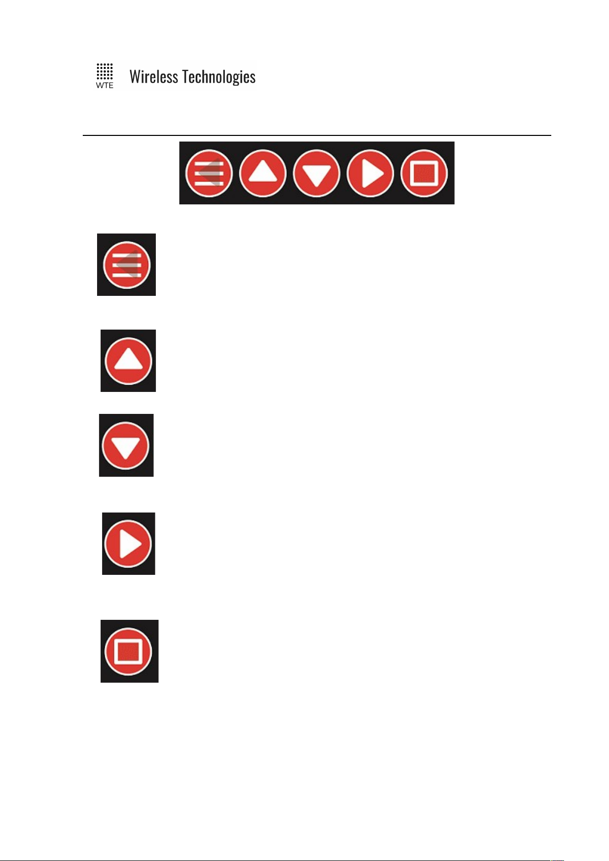
Buttons
MENU/BACK:
When on the MAIN SCREENS used to enter the MENU. When inside the
MENU, used to return back one level from within the MENU, until returning
back to the MAIN SCREENS.
UP:
When on the MAIN SCREENS used to cycle between sub-screens. When in
the MENU used to navigate or alter selected configuration items.
DOWN:
When on file related screens of the MAIN SCREENS shifts between entries.
When in the MENU used to navigate or alter selected configuration items.
RIGHT:
When on the MAIN SCREENS used to cycle between main screen. Within
the MENU used to enter sub MENU items or select items for configuration.
ENTER:
Used to select file related items from within the MAIN SCREENS.
© WTE Limited, 2018 – Christchurch New Zealand Page 13 of 158
TReX User Manual v2.14 Firmware
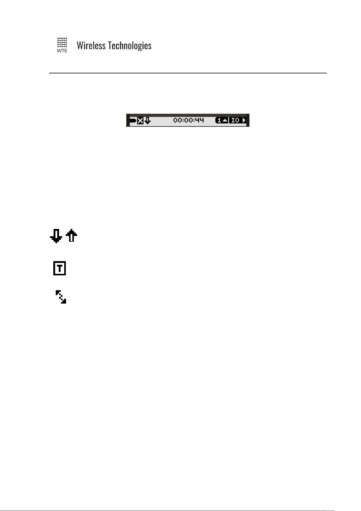
Main Screens
The TReX top icon bar provides information about the display screen and operating
status. .The far right text indicates the selected main screen. This is either “IO” (inputs and
outputs), “TX” (transmit) or “RX” (receive).
The far left icon indicates system voltage as a proportion of the configured high and low
battery levels (MENU->INPUTS->BATT HIGH/LOW V).
The “X” icon is visible when no messages have been received for 2 minutes and on start-up.
The time in the middle is the current RTC time (MENU->SYSTEM->TIME).
The “S” letter indicates that the master or slave SCADA telemetry modes are in operation.
The “M” letter, when present indicates that a Modbus telemetry request packet has been
processed within the last 2 seconds.
The “Incoming” down arrow indicates that the TReX is receiving (absent when
RX is DISABLED). The “Outgoing” up arrow indicates that the TReX is
transmitting (if a transmitter enabled TReX).
The Icon “T” below indicates the TReX has been configured for telemetry standalone “Back-to-Back Mirror Mode”.
The back to back arrows indicate the unit is operating in “Serial Link”
Telemetry mode.
© WTE Limited, 2018 – Christchurch New Zealand Page 14 of 158
TReX User Manual v2.14 Firmware
IO Screens
Screens that relate to inputs and outputs.
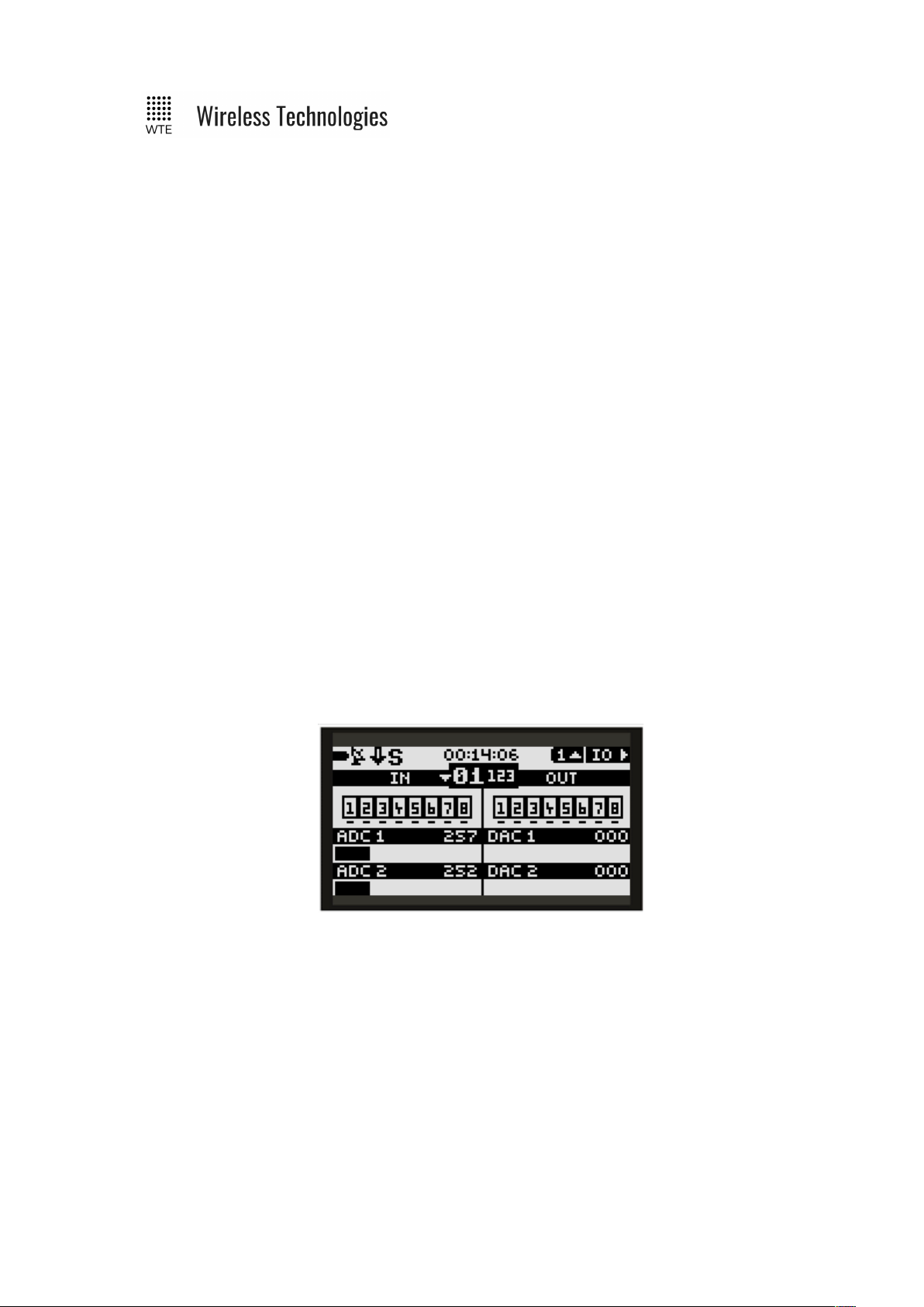
IO (1):
All input and output states. Each IO highlighted state changes if the IO level is HIGH or
LOW. There is a small line above each input or output if HIGH, and a line below if LOW. All
ADCs (analog inputs) and DACs (analog outputs) show a bar graph as a proportion of full
scale and display a raw count from 0-1023. When scaling has been applied to an analog
output, the DAC value shown is the unscaled value.
In the middle, shown in larger text is “01”. The number“01” in this case is the telemetry UNIT
ID. When TELEMETRY->MODE is configured to SCADA_MASTER a small down arrow
may be visible if the TELEMETRY->REMOTES have been configured to be more than 0.
Pressing the down arrow (when configured as a SCADA_MASTER) allows the UNIT ID to be
cycled to view the IO of each remote slave in the system – allowing a possible system of up to
88 digital IO, 22 ADCs and 22 DACs to be viewed.
Next to the UNIT ID is the smaller number “123”. Each TReX resets this number to the LINK
FAIL TIME each time a message is decoded. This “link count” reduces, and if reaches 0, the
link fail output can be operated.
SCADA_MASTER TReX units allow the “link count” to be viewed for all remote TReX
SCADA_SLAVE units.
© WTE Limited, 2018 – Christchurch New Zealand Page 15 of 158
TReX User Manual v2.14 Firmware
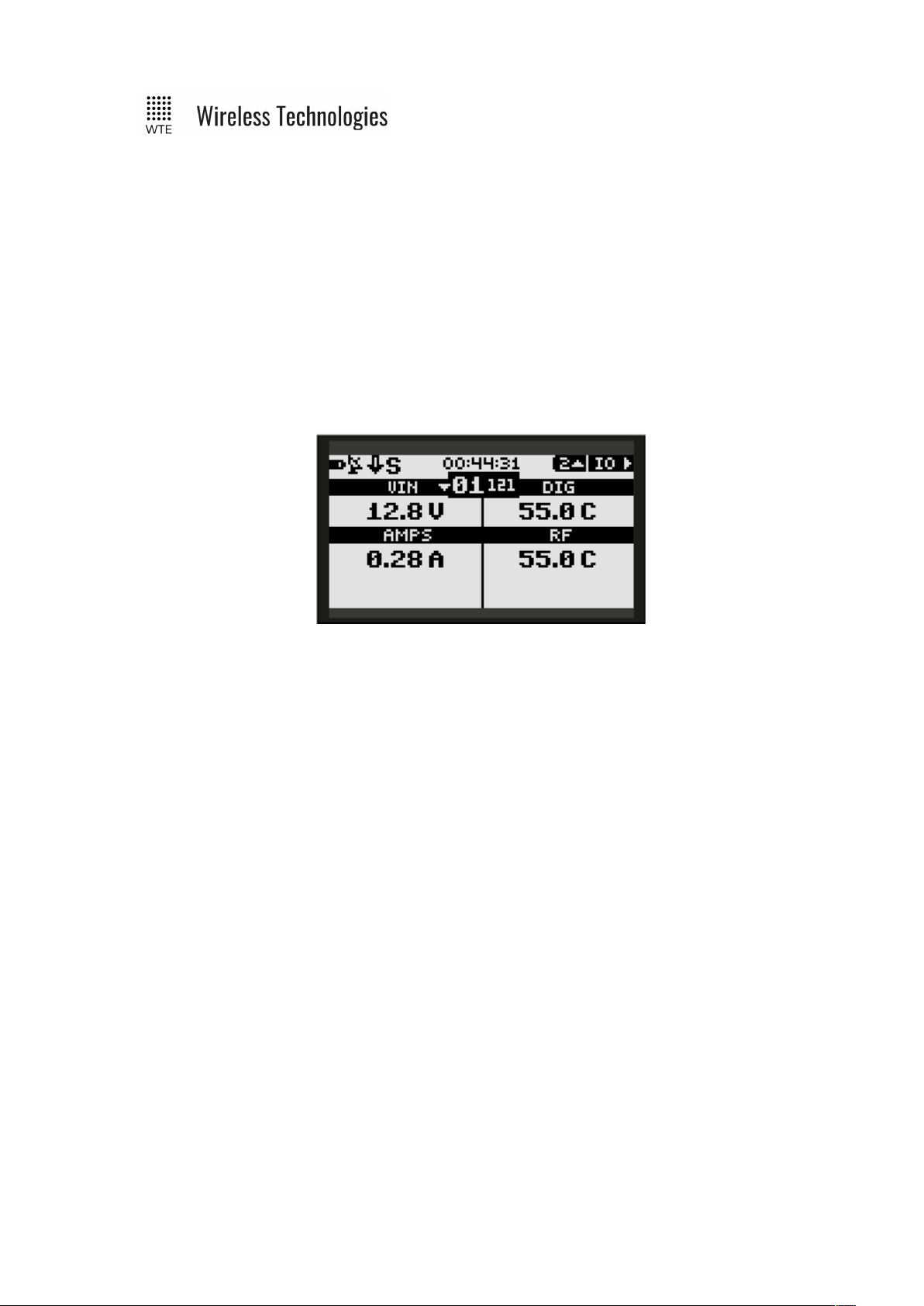
IO (2):
System voltage, current and internal operating temperature. RF is the temperature read directly
next to the RF power stage and will be higher than than the DIG board temperature while the
TReX is transmitting (not applicable for receiver only TReX units). Temperatures of the RF
power stage may reach 100 degrees Celsius under normal long term operation. These
temperatures are not the ambient temperature. The case of the TReX will NOT reach these
temperatures.
As with the previous IO screen, systems voltages and temperatures of all SCADA_SLAVE
TReX units (up to 10 SLAVE units) can be viewed by pressing the down button if the TReX is
configured to be a SCADA_MASTER.
© WTE Limited, 2018 – Christchurch New Zealand Page 16 of 158
TReX User Manual v2.14 Firmware
TX Screens
Screens that relate to messages transmitted.
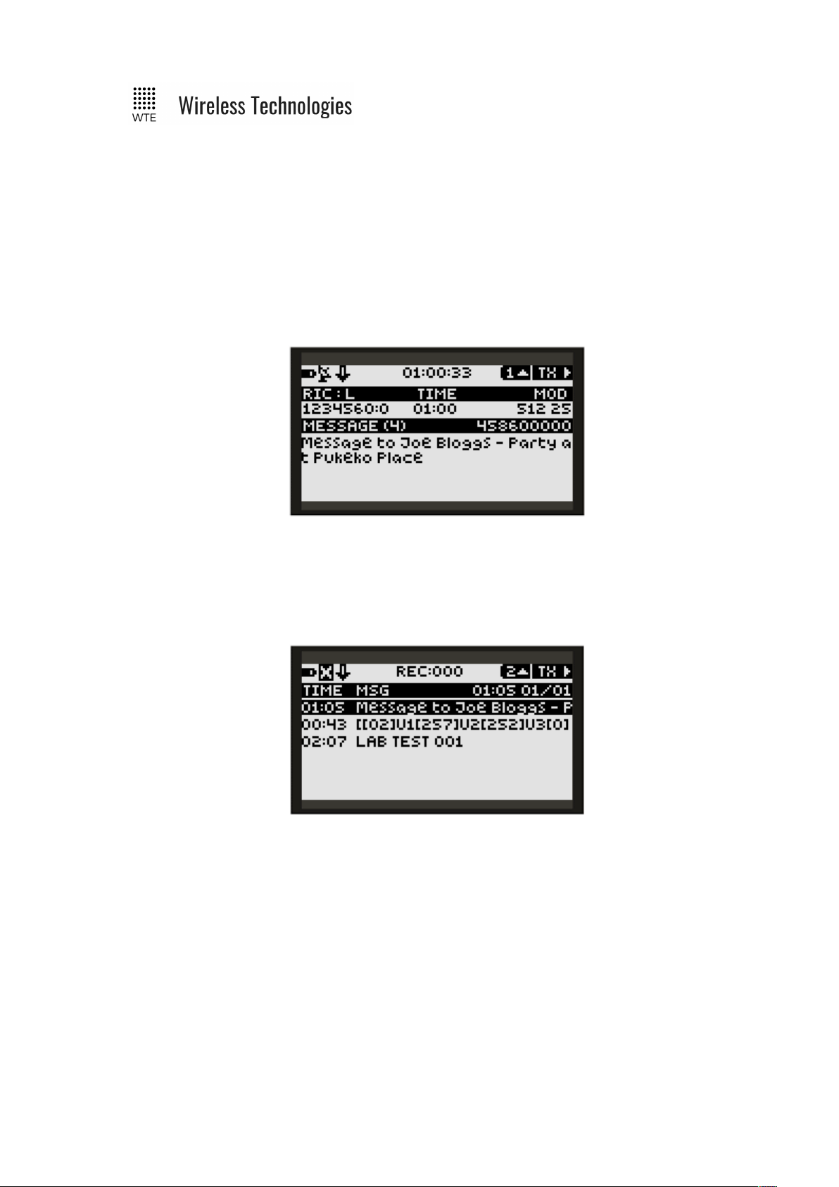
TX (1):
Last message transmitted. Includes the time the message was transmitted, message RIC (radio
identifying code/CAP Code) and level (0-3). To the right the modulation type and rate is
displayed also with the transmit frequency.
TX (2):
List of all time-stamped messages retrieved from internal storage. Most recent message
displayed at top. Next sub-screen can only be selected when top entry is displayed. Note that
messages are only available here when TX logging has been enabled (MENU->TX->MSG
LOG).
When an entry is selected pressing the UP/DOWN buttons, pressing the ENTER button
displays the entire message.
© WTE Limited, 2018 – Christchurch New Zealand Page 17 of 158
TReX User Manual v2.14 Firmware
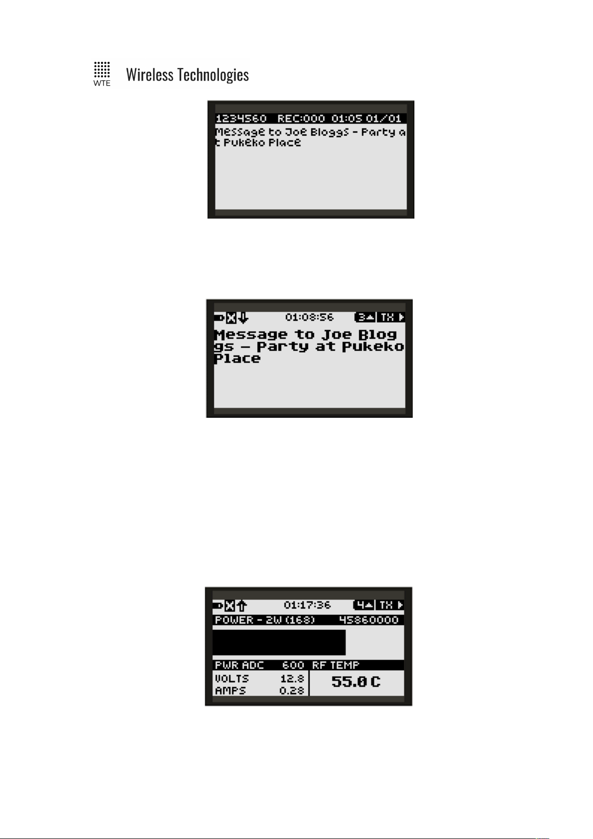
TX (3):
Displays the last transmitted message in large font. If the message exceeds the screen size, the
DOWN button allows scrolling.
TX (4):
A TX power bar graph is displayed as a proportion of full power during a message
transmission. Above the power bar is the text “POWER – 2W (168)”. “2W” relates to the
power setting in use. In brackets is the power amplifier DAC setting which is for factory use
only.
The POWER ADC count is used to indicate forward power. RF TEMP relates to the RF
amplifier temperature (not ambient) in degrees Celsius. VOLTS is the supply voltage and
AMPS is the total supply current.
© WTE Limited, 2018 – Christchurch New Zealand Page 18 of 158
TReX User Manual v2.14 Firmware
RX Screens
Screens that relate to messages received. Note, when messages are received, additional icons
may be displayed in the top bar.
The second left icon changes from the “X” icon to the satellite icon when a message has been
received. This indicates that the receiver is operational.
When the “BELL” icon is displayed with a following number, this means that system ALERTS
are enabled. See ALERTS for ALERT configuration and operation.
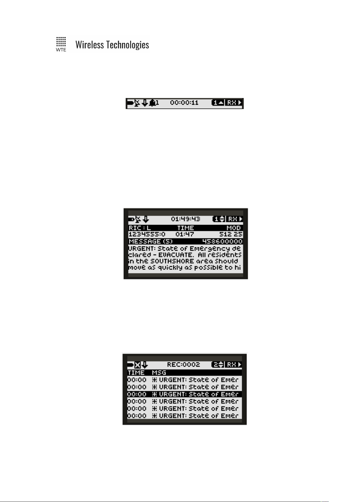
RX (1):
Basic summary of last received message. If the message is too large to fit on the screen the
DOWN arrow will be visible in the title bar. Pressing the DOWN button will now scroll
through the rest of the message.
RX (2):
List of all time-stamped received messages retrieved from internal storage. Most recent
message displayed at top. Next sub-screen can only be selected when top entry is displayed.
Note that messages are only available here when RX logging has been enabled (MENU->RX>MSG LOG).
Messages starting with “*” are messages that met the ALERT filter requirements, and were
eligible to operate the ALERT output when logged.
© WTE Limited, 2018 – Christchurch New Zealand Page 19 of 158
TReX User Manual v2.14 Firmware
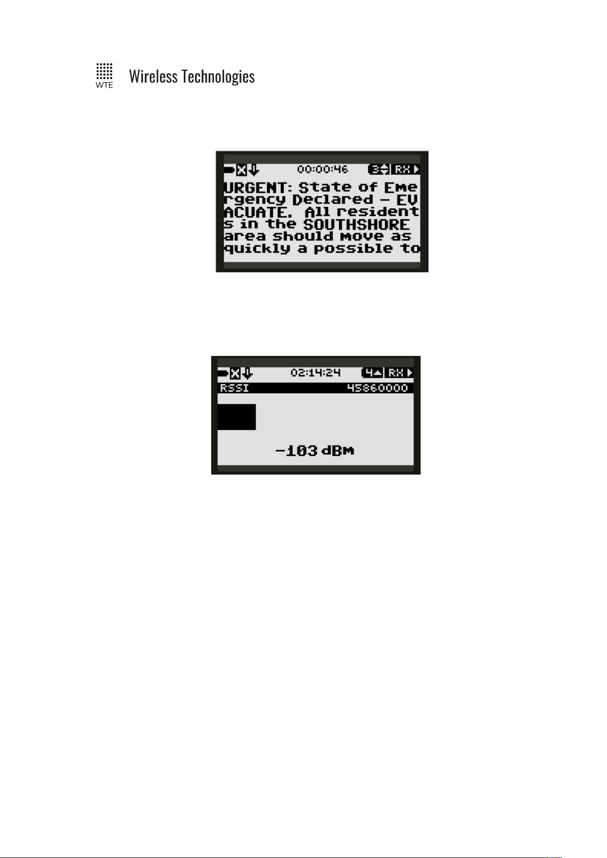
RX (3):
Displays the last received message in large font. If the message exceeds the screen size, the
DOWN button allows scrolling.
RX (4):
Displays the signal strength of the configured channel in real time. Displays signal strength
from -128dBm to 0dBm.
© WTE Limited, 2018 – Christchurch New Zealand Page 20 of 158
TReX User Manual v2.14 Firmware
Site Configuration Tools
The TReX includes tools to ensure suitability for use at the current location and quality of the
installation.
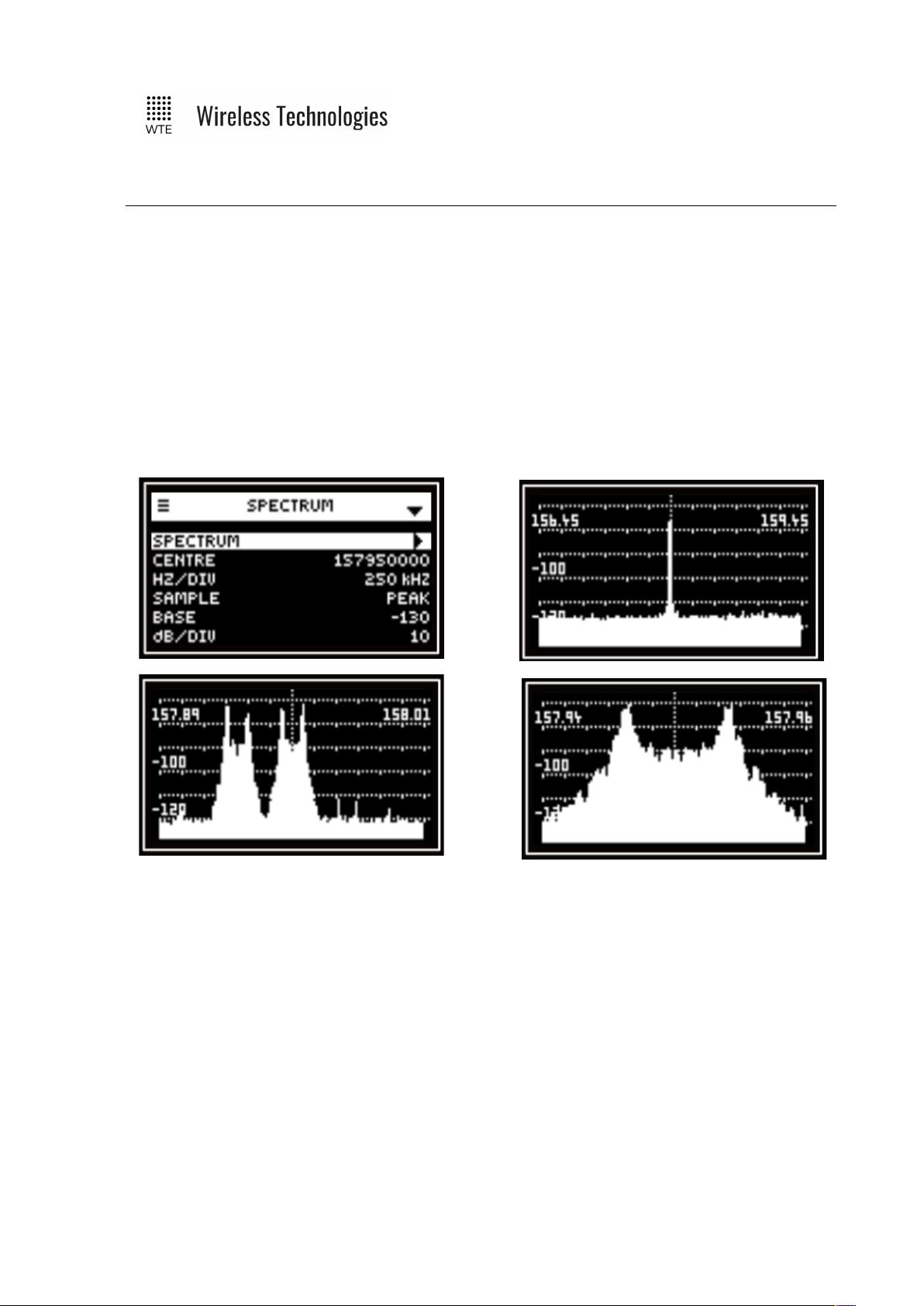
Spectrum Analyser
The optional spectrum analyser is a very simple to use tool that provides a span of either
3MHz, 120kHz or 24kHz around a configured test frequency. The receive bandwidth down to
500Hz is suitable for inspection of potentially interfering adjacent channel signals. The
analyser can display signals as low as -125dBm making and is suitable for site inspection. This
is an optional feature that requires a feature key to be purchased.
© WTE Limited, 2018 – Christchurch New Zealand Page 21 of 158
TReX User Manual v2.14 Firmware
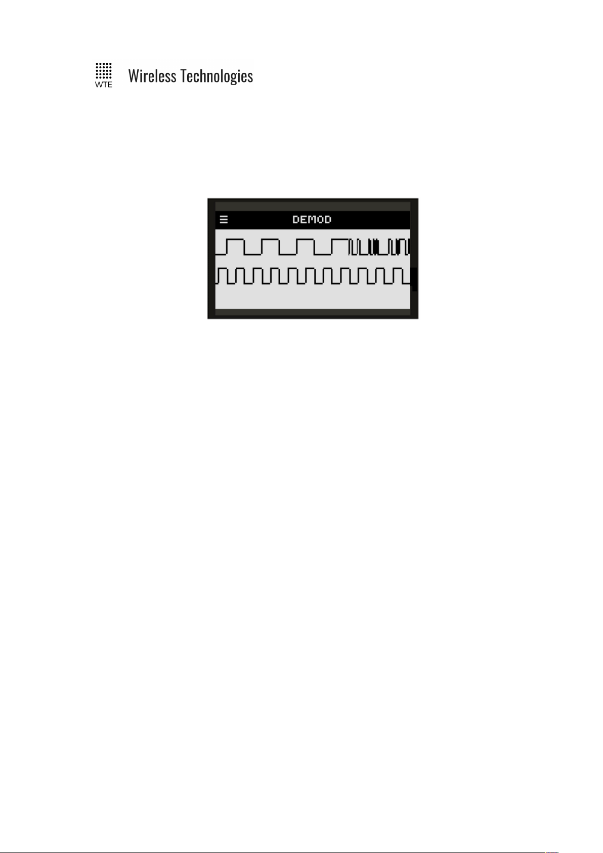
Demodulated Signal Viewer
The demodulated signal viewer allows inspection of raw demodulated data and the recovered
clock from that data. This is useful for viewing channel activity. This facility is available for 2
level modulation modes of operation. 4 level modulation modes will display as straight lines.
© WTE Limited, 2018 – Christchurch New Zealand Page 22 of 158
TReX User Manual v2.14 Firmware
Two-Way Paging
The TReX supports two-way paging. The TReX can return responses via serial or TCP
connections. Transmitter capable TReX units can additionally respond at high power across
the air.
Not only can acknowledgements be returned from the TReX, but confirmation of job
acceptance receipts can be returned. This means that messages can be sent to single or
multiple TReX units and clear details can be returned to notify if a message has been read or
an action is being performed.
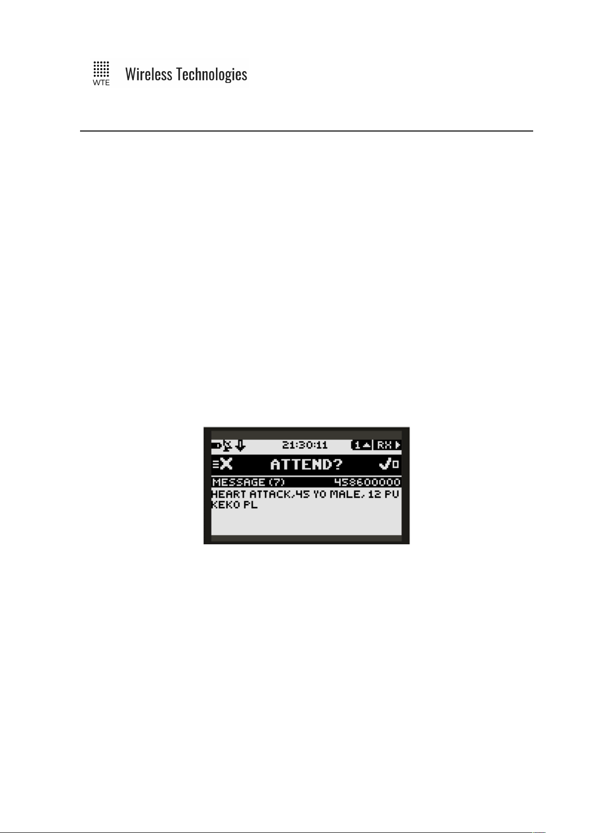
Example:
An emergency dispatch system may send a paging message to a group of ambulances for
attendance at an emergency. The message will be displayed on a TReX unit within the
ambulance with prompt to attend if possible. Accepting the job can be performed with a
simple keypress that will send receipt to the dispatch system that the vehicle is on-route.
See WTE Ack and Confirm Protocol for usage details.
With a single keypress, key messages can be responded to. Details of the responder are
returned and logged.
© WTE Limited, 2018 – Christchurch New Zealand Page 23 of 158

TReX User Manual v2.14 Firmware
Configuration Methods
There are several methods to configure the TReX unit, such as:
• Directly from the front panel
• Via a web browser
• Via Serial terminal over the RS232, RS422 and or RS485.
• Via a TCP terminal (either client or server).
• USB connection and editing of the WTE_CONF.INI configuration file.
© WTE Limited, 2018 – Christchurch New Zealand Page 24 of 158
TReX User Manual v2.14 Firmware
Front Panel Menu Configuration
All typical configuration items are accessible and configurable via the on-board menu system.
This includes the ability to configure input messages. Through the use of the menu system the
TReX is able to be set up and configured without any PC connection.
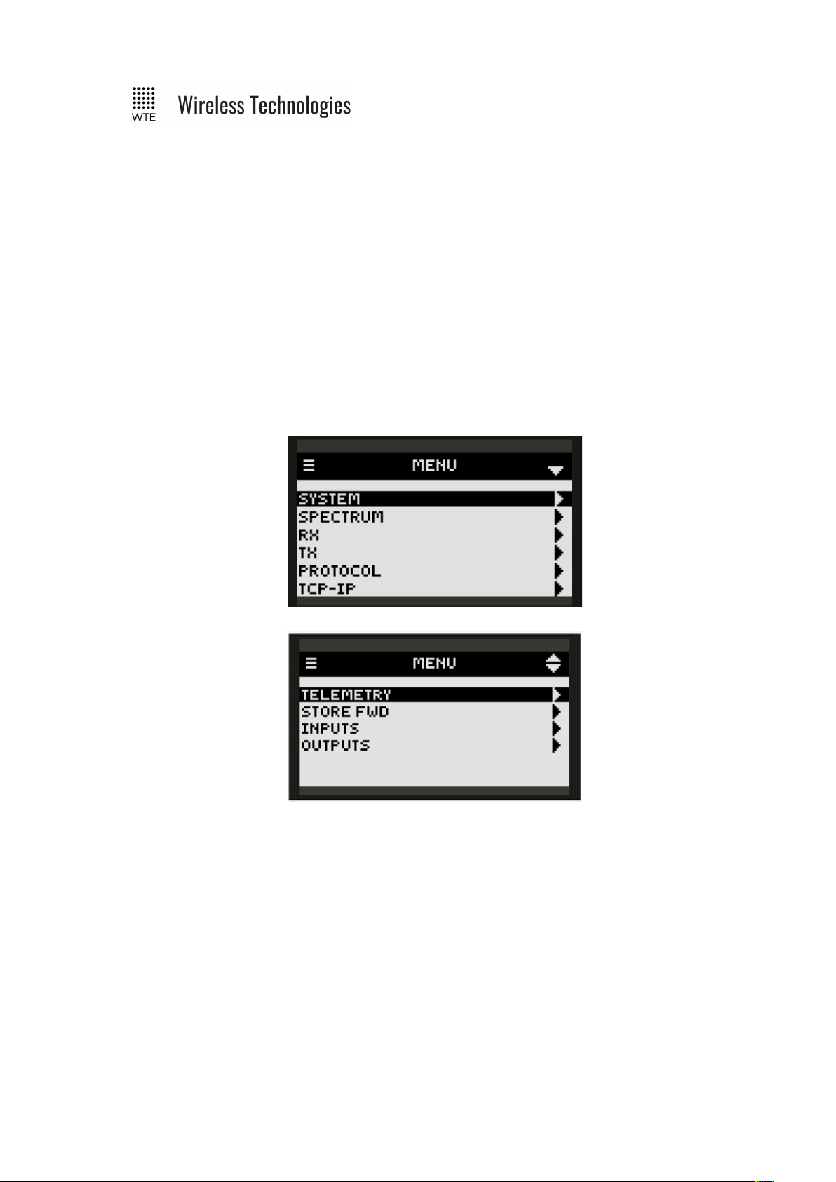
To enter the menu, press the MENU button. The top line icon bar shows when the DOWN
button can be used when the DOWN arrow is visible. When scrolling down and the DOWN
arrow disappears, then the end of the menu section has been reached. The UP arrow will be
visible when navigation in the up direction is permissible. The RIGHT arrow indicates that the
RIGHT button can be pressed to enter a MENU category when highlighted.
Pressing the MENU button again moves back one level, until the top is reached, and then the
TReX leaves the MENU mode. If any change has been made, changes will only be written to
internal storage when leaving the MENU mode.
© WTE Limited, 2018 – Christchurch New Zealand Page 25 of 158
TReX User Manual v2.14 Firmware
To edit any field, first move to the item, press RIGHT to select the field. Once highlighted, the
UP/DOWN arrows change the field. On completion, pressing RIGHT again will deselect the
field.
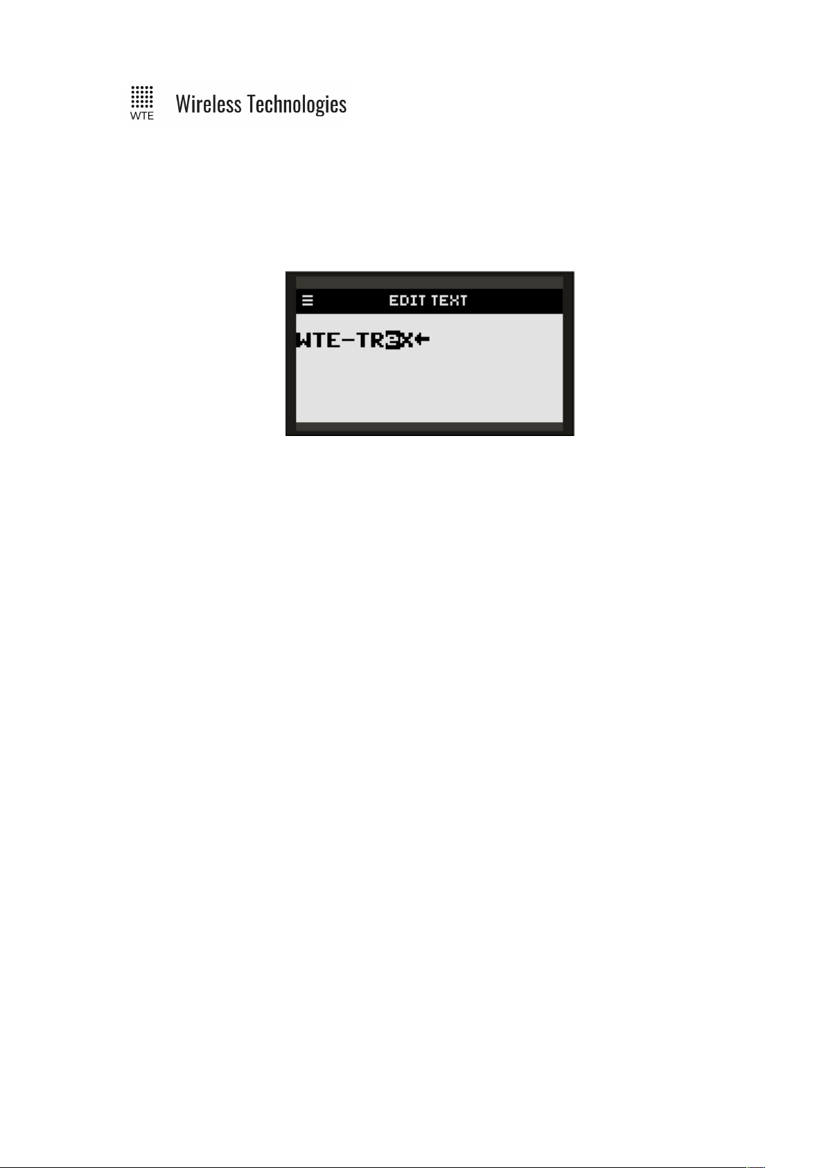
Some fields are text that can be edited. There is a built-in text editor. Fields that are edited by
the text editor are presented with the title “EDIT TEXT”.
Each character can be selected by pressing the RIGHT button. The selected character is
inverted. Pressing the UP/DOWN buttons allows the character to be changed to any printable
character. The BACK arrow indicates the end of the text. This arrow is not part of the actual
text but present as a marker. To make the text longer, highlight the BACK arrow and change
the character using the UP/DOWN buttons. To make the text shorter or to delete a character,
highlight the BACK arrow and press the ENTER button. Press the BACK button to exit the
editor.
© WTE Limited, 2018 – Christchurch New Zealand Page 26 of 158
TReX User Manual v2.14 Firmware
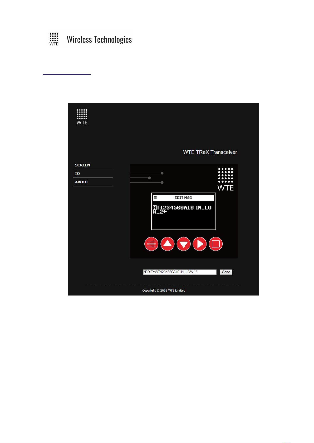
Web Browser Configuration
For web browser configuration to be possible (using browsers that support SVG such as
“Chrome”, “Firefox” etc.), the Ethernet/IP must be ENABLED via the menu (ENABLED by
default). This is located in SYSTEM->IP. In this menu section network parameters can be
configured such as the IP, Mask and gateway.
Only a single connection to the TReX should be allowed. Multiple connections will result in
impaired responsiveness.
© WTE Limited, 2018 – Christchurch New Zealand Page 27 of 158
TReX User Manual v2.14 Firmware
After the unit has been enabled to be use over the web, a web browser address matching the
configured IP should be used. e.g.
http://192.168.1.20
This IP address is shown as a pop-up each time the TReX starts up.
Using the web browser the TReX can be remotely configured. When moving to a text field,
the text box at the bottom of the browser is automatically loaded. Changes can now be made
and committed by pressing the SEND button. This text box can also be used to transmit
messages for a configured protocol.
© WTE Limited, 2018 – Christchurch New Zealand Page 28 of 158

TReX User Manual v2.14 Firmware
Serial Command Configuration
Parameters can be changed using any common serial terminal (available on request if required)
program using the RS232 or RS422/485 ports.
Start-up baud rate is determined by the baud rate as configured through the MENU.
All configuration commands always start with the asterisk ‘*’ character.
All messages that do not start with the * character are processed by the protocol decoder.
All messages are terminated by a Carriage Return character, shown in this manual as <CR>
All commands that accept a value, can have that value read back by using the ‘?’ suffix.
Typical usage:
*RX_FREQ?
Typical response:
*RX_FREQ=160000000
There are some commands that support multiple entries (such as the same command but for
different ranges). In this case the question mark can be followed by the parameter to be
interrogated. E.g.
*RX_RANGE?<CR>
Returns (lists all ranges)
*RX_RANGE=1:8,2000000
*RX_RANGE=2:0,0
*RX_RANGE=3:0,0
*RX_RANGE=4:0,0
*RX_RANGE=5:0,0
*RX_RANGE=6:0,0
*RX_RANGE=7:0,0
*RX_RANGE=8:0,0
To find the first range only:
Usage:
*RX_RANGE?1<CR>
Response:
*RX_RANGE=1:8,2000000
In order for any configuration changes made via serial to be saved the command *SAVE<CR>
must be sent to the TReX before removing power or restarting.
Note: Although most configuration changes are applied immediately, it is a good practice to
© WTE Limited, 2018 – Christchurch New Zealand Page 29 of 158

TReX User Manual v2.14 Firmware
restart the unit after changing configuration. This can be achieved by removing power to the
unit or sending the *REBOOT<CR> command.
© WTE Limited, 2018 – Christchurch New Zealand Page 30 of 158

TReX User Manual v2.14 Firmware
MENU Configuration
SYSTEM
Configures language, backlight, time, unit ID, sound, baud rates, factory test, main operating
screens and menu lockout.
TX
Transmitter configuration items. Includes frequency, baud rates and logging settings.
RX
Receiver configuration items. Includes frequency, baud rates and logging settings.
SPECTRUM
Configures and allows access to the spectrum analyser.
PROTOCOL
Control of the formatting in and out of the TReX for incoming and outgoing messages.
TCP-IP
Control of all aspects of internet connectivity. Allows remote configuration and operation
through the use of the “Chrome” or “Firefox” web browser, TCP client or TCP server.
TELEMETRY
© WTE Limited, 2018 – Christchurch New Zealand Page 31 of 158

TReX User Manual v2.14 Firmware
Determines if operation is on a controlled protocol basis, or autonomously operating input
states to a remote TReX device.
STORE FWD
Configuration of the paging store and forward repeater operation including duplicate reject.
INPUTS
Configuration of all inputs.
OUTPUTS
Configuration of all outputs. Also responsible for assigning of alerting functions to any output.
© WTE Limited, 2018 – Christchurch New Zealand Page 32 of 158

TReX User Manual v2.14 Firmware
SYSTEM Menu
LANGUAGE
Items ENGLISH plus others can be selected. To incorporate specific language support please
contact WTE Limited directly.
BACKLIGHT
The backlight setting is how long in seconds the backlight is lit after each key press and also
when a message is received. Setting to 0 disables the backlight completely.
TIME
Sets the internal clock.
© WTE Limited, 2018 – Christchurch New Zealand Page 33 of 158

TReX User Manual v2.14 Firmware
ID
This is the unit ID that is used by the WTE output control protocol. This can be any number of
alpha numeric description. e.g. “01” or “Unit-A”
SOUND
Allows control of system sounds that may be heard on an ALERT and also key beeps.
Items ON and OFF can be selected.
RS232 BAUD
Allows configuration of the RS232 port baud rate. All settings are N:8:1. Available rates are:
2400, 4800, 9600, 38400, 57600 and 115200.
Note: that for the most efficient transmission, the serial baud rate should be higher than the
transmit over the air baud rate.
RS422 BAUD
Allows configuration of the RS422 port baud rate. All settings are N:8:1. Available rates are:
2400, 4800, 9600, 38400, 57600 and 115200
Note: that for the most efficient transmission, the serial baud rate should be higher than the
transmit over the air baud rate.
MAIN SCREEN
This allows any page on any main screen to be set as the default main screen. This results in
this screen being the screen that is first seen when powering up the unit, or after any period of
inactivity the TReX will automatically revert to this screen.
Setting to DEFAULT will unset the last custom set screen and will return to the factory default
main screen. Setting to SET will set the screen to be the screen that was last used before
entering the menu.
MENU PIN
When the MENU PIN is set to a non-zero value, the MENU will be prevented from opening
until the PIN is entered. Prevents accidental or unauthorised misconfiguration. If the PIN is
ever forgotten, the PIN is visible using the command *CONFIG or viewing the
WTE_CONF.INI file through a USB connection. Once the MENU is unlocked, it will remain
unlocked until the unit is restarted.
FACTORY
Sub menu responsible for calibration screens and setting of feature unlock keys.
TEST
Test sub menu for generation of test messages and testing of outputs.
© WTE Limited, 2018 – Christchurch New Zealand Page 34 of 158

TReX User Manual v2.14 Firmware
REGULATORY
Regulatory items such as FCC-ID*.
*Note: Publication number 784748-D01, FCC-Part 90 allows for devices with integrated
display to not require a printed label on the device holding this information.
© WTE Limited, 2018 – Christchurch New Zealand Page 35 of 158

TReX User Manual v2.14 Firmware
TEST Sub Menu
1-8
Digital output to test. Pressing up pulls the output to ground for 60 seconds. Pressing down
releases the output.
© WTE Limited, 2018 – Christchurch New Zealand Page 36 of 158

TReX User Manual v2.14 Firmware
FACTORY Sub Menu
This menu is typically for factory use only or to return the unit to a factory new state.
DIAGNOSTICS
Debug for factory use only.
SERIAL NUM
Read only unit serial number.
KEY
The key used to unlock unit features. If features are purchased after sale, a new key may be
required to be entered here. They key is unique to the unit serial number.
SET DEFAULTS
Used to set the TReX back to factory defaults. Calibration data is not cleared. This may be
used at any time to restore the unit to a known starting point.
© WTE Limited, 2018 – Christchurch New Zealand Page 37 of 158

TReX User Manual v2.14 Firmware
TIME Sub Menu
HOUR, MIN, DAY, MONTH and YEAR
Configuration of the real time clock.
SOURCE
Determines how time is maintained in the TReX.
• RTC uses the internal real time clock to keep time.
• FLEX takes the time from the FLEX transmission time details (if present).
• SEQ TEST takes the time from national paging network (used in N.Z. only).
• NONE only uses the internal processor clock. This will only be the time since last
reset.
© WTE Limited, 2018 – Christchurch New Zealand Page 38 of 158

TReX User Manual v2.14 Firmware
SPECTRUM Menu
SPECTRUM
Displays the radio spectrum using the settings in this menu. Signals between -128dBm and
0dBm can be displayed. Power levels above 17dBm (50mW) will destroy the receiver
input.
CENTRE
Displays the centre frequency to be displayed on the screen.
HZ/DIV
Either 250kHz, 10kHz or 2kHz. The screen is 6 divisions wide in 120 steps.
The RBW (receiver bandwidth) and frequency span is automatically set when the Hz/Div
changes.
HZ/DIV
RBW Frequency Span
250kHz 25kHz 3MHz
10kHz 1kHz 120kHz
2kHz 500Hz 24kHz
SAMPLE
When set to CONT the spectrum analyser screen will be updated with new values
approximately twice a second. When set to PEAK only higher values will be written to the
screen. At any time, the ENTER button can be pressed on the SCREEN to clear the screen and
load new PEAK values.
BASE
Defines the base signal level on the screen. When set to -100, only signals with a strength
greater than -100 dBm will be displayed. Range is -130 dBm to -60 dBm.
dB/DIV
© WTE Limited, 2018 – Christchurch New Zealand Page 39 of 158

TReX User Manual v2.14 Firmware
Scales the signal level displayed. Either 10 dB/DIV or 20 dB/DIV can be set. When 20 is set a
dynamic range of 120 dB is possible.
© WTE Limited, 2018 – Christchurch New Zealand Page 40 of 158

TReX User Manual v2.14 Firmware
RX Menu
RX
When ENABLED the TReX receiver is enabled. When DISABLED an operating current
reduction of 50mA is typical.
FREQUENCY
Specifies the receive frequency in Hz (range limited to the variant of product).
MODULATION
Specifies modulation parameters. This includes whether the modulation is 2 or 4 levels GFSK
plus the channel width. 512_25 indicates 512 baud with 25kHz channel spacing (2 level
GFSK). 9600-4L_6 indicates 9600 baud with a 6.25kHz channel spacing (4 level GFSK).
Modulation rates from 512 baud to 48K baud can be set.
PROTOCOL
Specifies the protocol to apply for serial output, accepts WTE, CUSTOM, RAW and AUX.
Other protocols may be added and supported upon request.
MODE
© WTE Limited, 2018 – Christchurch New Zealand Page 41 of 158

TReX User Manual v2.14 Firmware
Specifies the transport mode of the receiver (how the information is received over the air).
• POCSAG_A must be used in order to receive alphanumeric messages.
• POCSAG_N must be used in order to receive numeric messages.
• WTE_EN must be used in order to receive 8 bit characters (POCSAG_A transmits 7
bit characters only).
• FLEX must be used in order to receive and decode 2 level 1600 baud FLEX messages.
MSG LOG
When ENABLED all received messages are written to RX-LOG.TXT on the SD card. Should
be set to DISABLED in critical applications when the SD card cannot be allowed to
completely filled (such as when unsupervised).
DISABLED:
Messages are not logged.
ENABLED:
All messages displayed are written to internal SD card and can be viewed on the message
history screen.
CLEAR:
Setting to CLEAR will result in RX-LOG.TXT being deleted when exiting the menu.
RIC RANGES
Specifies up to 8 RIC RX ranges for decoding. Messages received with RIC codes not allowed
with the RX_RANGE will be discarded by the receiver.
Note: When configuring the RIC RANGE, the LOW RIC must not be higher than the HIGH
RIC and the HIGH RIC must not be lower than the LOW. Any attempt to configure illegally
will reset the RIC RANGE to ensure these rules are not broken. Any RIC RANGE with a
LOW RIC set to 0000000 will NOT be used.
BUSY LEVEL
Specifies the busy level for the configured channel.
The configured value is the signal level from 0 to -130 (in dBm). If the signal strength on the
receiving channel is above this configured value, the channel will be considered to be busy.
Transmissions will not be possible if the channel is considered to be busy. After a period of 5
seconds of the channel being busy, the transmitter will transmit anyway.
Note: If the TReX continually reports BUSY, issue the command *RSSI<CR> (or view the
RSSI screen) to inspect the noise floor and adjust the busy level appropriately.
© WTE Limited, 2018 – Christchurch New Zealand Page 42 of 158

TReX User Manual v2.14 Firmware
LINK FAIL TIME
This is the number of seconds (up to 240) that is allowed to pass in-between received messages
without setting the LINK FAIL output (if LINK FAIL output is configured).
ALERT
Visual notification and repeating beep (at a configurable interval) when a message is received
that meets the conditions for raising an alert. See ALERT FILTER.
If the ALERT output is enabled the configured output will also operate.
Can be configured from 0-250 seconds. When set to 0 the alert is disabled.
DEMOD
Access to the raw signal demodulation screen allowing raw data and recovered clock signals to
be viewed in real time.
FILTERS
The TReX supports the use of message filters. These filters inspect the content of incoming
messages and then make decisions on whether to ignore or pay attention to these messages
based on filter setting.
There are 3 types of supported filters:
• Include filters (messages must include one or more of the matching entries).
• Exclude filters (messages must NOT include any of the matching entries).
• Alerts filters (Alerts are raised for message with any of the matching entries).
Alert filters take priority over Exclude filters. This means that if “PUKEKO” has been
specified in ALERT.TXT and “FIRE” is specified in EXCL.TXT then a message with “FIRE
AT PUKEKO PLACE”, although it would normally be excluded, would still raise an alert and
display the message.
Each of the filter matching entries are NOT case sensitive and can be part of a longer word or
phrase.
Entries are allowed to be more than one word e.g.
THIS IS A TEST
This will match on “ThiS is a TEST” but not the single words in the entry, unless they have
been added as separate match entries.
Up to 15 key words can be stored, each up to 20 characters in length. There must be no ASCII
© WTE Limited, 2018 – Christchurch New Zealand Page 43 of 158

TReX User Manual v2.14 Firmware
control characters within the key words used and each matching phrase must be on a new line.
ALERT FILTER
This filter option allows the use of a text file called “ALERT.TXT” to be stored and modified
on the SD card (accessible via the USB port). If the feature is enabled (ALERT set to value),
this file (if present) will be searched for key words. If any of these key words are found then
an alert is raised based on the alert configuration (beep plus operation of a configured output).
Example:
A text file named ALERT.TXT is added to the SD card root directory that has the following
contents:
TSUNAMI
MAJOR EMERGENCY
All messages WITH these key words will result in an alert being raised. These messages will
be displayed and logged normally as per the system configuration.
All other messages will still be decoded and displayed based on RIC range settings.
ALERT set to DISABLED:
Messages are not filtered to raise an alert. When DISABLED messages can still raise alerts
based on the alert settings within the menu.
ALERT set to a value:
Messages are filtered to raise an alert. When set to a value only the messages found in the
ALERT.TXT file will raise an alert. No other messages, even if displayed will raise an alert.
NOTE: Filtered messages must still fall within configured RIC ranges in order to be displayed.
NOTE: When the ALERT.TXT filter option has been set a value (enabled), alerts are raised by
matching key words in arriving messages that are within the specified RIC range. When this
option is ENABLED, only the messages matching these key words will raise an alert (beep and
or output changing state). All other incoming messages within the RIC range configured will
no longer raise any alert (as is the case when ALERT.TXT is absent).
NOTE: Restarting is required in order to load the ALERT.TXT settings. This applies both
when enabled via the serial port or from the menu.
INCL FILTER
This filter option allows the use of a text file called “INCL.TXT” to be stored and modified on
the SD card (accessible via the USB port). If the feature is ENABLED, this file (if present)
will be searched for key words. Any of these key words MUST be present in order for the
message to be processed.
NOTE: messages received for filtering must still fall within configured RIC ranges.
Example:
A text file named INCL.TXT is added to the SD card root directory that has the following
© WTE Limited, 2018 – Christchurch New Zealand Page 44 of 158

TReX User Manual v2.14 Firmware
contents:
FIRE
EMERGENCY
All messages WITHOUT these key words WILL BE DISCARDED. Even though non
matching messages are discarded, the receiver OK indicators and timers will continue to
operate normally.
INCL FILT set to DISABLED:
Messages are not filtered
INCL FILT set to ENABLED:
Messages are filtered
EXCL FILTER
This filter option allows the use of a text file called “EXCL.TXT” to be stored and modified on
the SD card (accessible via the USB port). If the feature is ENABLED, this file (if present)
will be searched for key words. Any of these key words MUST NOT be present in order for
the message to be processed.
Example:
A text file named EXCL.TXT is added to the SD card root directory that has the following
contents:
THIS IS A TEST
DISCARD
All messages WITH these key words WILL BE DISCARDED. Even though non matching
messages are discarded, the receiver OK indicators and timers will continue to operate
normally.
EXCL FILT set to DISABLED:
Messages are not filtered
EXCL FILT set to ENABLED:
Messages are filtered
© WTE Limited, 2018 – Christchurch New Zealand Page 45 of 158

TReX User Manual v2.14 Firmware
Protocol Menu
TX
Specifies the protocol to apply for serial input. Accepts WTE, CUSTOM, RAW, AUX and in
some cases others as required or specified.
RX
Specifies the protocol to apply for serial output. Accepts WTE, CUSTOM, RAW, AUX and in
some cases others as required or specified.
SENT RESP
This the response out the serial port at the completion of each transmitted message. By default
this is “Page Sent”.
Note: The default overriding response for WT protocol is “WT[xxx]”. To change the sent
response to “Page Sent” a leading ‘*’ character must be used. e.g. “*Page Sent”.
MODBUS
Specifies parameters used for the “MODBUS” protocol.
RAW
Specifies parameters used for the “RAW” protocol.
CUSTOM
Specifies parameters used for the “CUSTOM” protocol.
© WTE Limited, 2018 – Christchurch New Zealand Page 46 of 158

TReX User Manual v2.14 Firmware
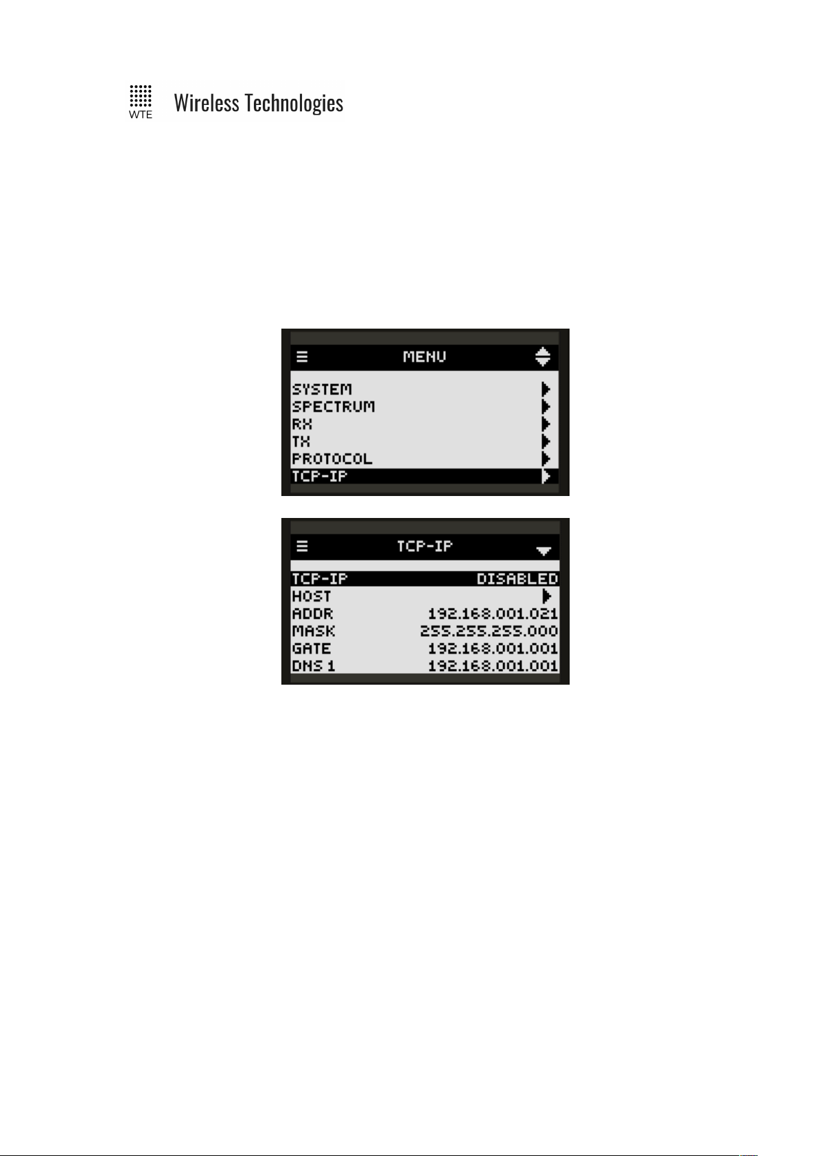
TCP-IP Menu
TCP-IP
The TCP-IP configuration lets you choose the TCP protocol for use on the TReX.
WEB:
This setting allows the TReX to be monitored and configured from a Chrome web browser
either on a PC or mobile device.
SERVER:
This setting allows the TReX to be operated as a TCP server on the specified TCP port.
SERVER would typically be used if a short term connection was required, such as to change a
configuration item or send a message for transmitting. Only a single connection is allowed,
however multiple users can conceivably connect in this mode for short durations in order to
offload content to be transmitted. A long term or held connection will allow decoded messages
to be viewed in real-time (preventing further connections).
CLIENT:
This setting allows the TReX to be operated as a TCP client on the specified TCP port and
REMOTE IP. SERVER would typically be used if a remote device required a long duration or
permanent connection. This would be desirable if monitoring decoded messages.
WEB+SERVER:
Concurrent WEB and SERVER functionality.
WEB+CLIENT:
© WTE Limited, 2018 – Christchurch New Zealand Page 47 of 158

TReX User Manual v2.14 Firmware
Concurrent WEB and CLIENT functionality.
DISABLED:
Setting to DISABLED ensures the maximum possible power savings even when an Ethernet
cable has been connected. When IP is DISABLED, current consumption will reduce by
approximately 150mA and disable the TCP stack.
HOST
This is the name that can be associated to the TReX. This name can be used directly instead
of the IP address to address the TReX. By default is “WTE-TReX”
ADDR
IP Address for access to the TReX.
MASK
IP Mask
GATE
IP Gateway
DNS1
Primary Domain Name Server
DNS2
Secondary Domain Name Server.
PORT
The port to use for TCP client TCP server connections. Default is 5080.
MAC
Non-editable MAC address.
© WTE Limited, 2018 – Christchurch New Zealand Page 48 of 158

TReX User Manual v2.14 Firmware
Telemetry Menu
MODE
DISABLED:
there are no autonomous transmissions.
SERIAL LINK:
Serial arriving on an enabled serial port is sent to a remote TReX unit.
IO MIRROR:
All local unit enabled inputs are mirrored to outputs of a remote device based on the IO
MIRROR configuration. IO_MIRROR can only support 2 TReX units. SCADA monitoring
and controlling is not possible in this MODE.
SCADA_MASTER (Optional feature only):
The TReX unit can be connected via Mobus (TCP or RTU serial). This unit can then
optionally report the status (and control) SCADA_SLAVE TReX units.
SCADA_SLAVE (Optional feature only):
The TReX can be installed in a remote location and wirelessly controlled by a
SCADA_MASTER. See SCADA Configuration.
LOCAL ID
It is possible to have many TReX units operating on the same frequency. This is the ID that
the REMOTE TReX needs to use in its REMOTE ID field in order to communicate.
REMOTE ID
© WTE Limited, 2018 – Christchurch New Zealand Page 49 of 158

TReX User Manual v2.14 Firmware
This is the ID of the remote device that all inputs will be sent to. When the MODE is
configured to be SCADA_MASTER this is the ID of the first SCADA_SLAVE TReX. All
SCADA_SLAVES must be consecutively numbered following this ID.
When the MODE SCADA_SLAVE is used, the REMOTE_ID is configured to be the same as
the LOCAL_ID (this is required by the SCADA_MASTER to identify the source of the
transmission).
REMOTES
This parameter is only used when the MODE is SCADA_MASTER. This is the number of
wireless SCADA_SLAVE units that the SCADA_MASTER will communicate with.
INPUTS
This is a shortcut to the INPUT configuration menu.
OUTPUTS
This is a shortcut to the OUTPUT configuration menu. If the OUTPUT is DISABLED, then
messages from a remote unit can NOT change the units outputs. This may be desired if the
OUTPUT is already configured for another purpose such as LINK FAIL OUTPUT. Outputs to
be used should be set to LATCHED.
REFRESH TIME
How long in seconds before sending all input information again. If any INPUT changes then
there is an immediate transmission. The REFRESH TIME ensures that if a message is lost, the
remote device will eventually resynchronise its OUTPUTS with the local device INPUTS.
DELTA ADC TX
Analog data is transmitted after each REFRESH TIME count elapses. This field allows an
immediate transmission if it has changed by a certain amount since its last transmission. This
is the raw ADC count that is a value up to 1023. Min value is 10 to ensure that very small
changes do not result in continuous transmissions in an electrically noisy environment.
SERIAL LINK
Configuration of all SERIAL LINK Settings
MODBUS
Configuration of all MODBUS Settings
© WTE Limited, 2018 – Christchurch New Zealand Page 50 of 158

TReX User Manual v2.14 Firmware
SERIAL LINK Menu
This a duplication to settings used by the RAW protocol. These settings allow the transmission
to be optimised.
TX TIMEOUT
This is the period of serial port inactivity in 10mS steps that the TReX will wait before
transmitting. In this case, placing a small delay between characters will result in poor
transmission efficiency.
TX LEN
This configures how many characters must be buffered before transmission. If the TX
TIMEOUT has been configured, then the TX TIMEOUT will take priority.
TX CHAR
This configures a special character that can be used to mark the end of a serial message. This
could be configured to be a carriage return for example (value to use is 13 for a carriage
return). When any carriage return character is seen, then an immediate transmission would be
forced. The TX LEN and TX TIMEOUT items take priority. The value of this configuration
item is the decimal value of the ASCII character. Please refer to a standard ASCII chart for
decimal values for ASCII characters (1-127).
© WTE Limited, 2018 – Christchurch New Zealand Page 51 of 158

TReX User Manual v2.14 Firmware
STORE FWD Menu
OPERATION
When store forward operation ENABLED the unit is used to listen to transmissions in the area,
decode the messages and retransmit again to provide greater coverage than would normally be
possible.
When DISABLED there is no store and forward function. The non zero value set is the delay
in 100ms steps after each transmission. This delay allows time for any downstream forwarding
equipment to clear the message. All messages received are immediately queued for
transmission, and up to 5 messages may be retransmitted after the store forward delay.
DUPL REJECT
Setting to 0 disables the feature, otherwise this is the number of seconds to reject identical
messages for up to 60 seconds. Duplicate rejection operates only on messages decoded for
forwarding. This means that receiving of duplicate messages is not prevented (nor the
transmission of same messages resulting from a protocol command), but when used as part of a
simple store forward system re-queueing of messages can be controlled. Duplicate reject only
tests the previous 10 messages in the historic transmit queue.
© WTE Limited, 2018 – Christchurch New Zealand Page 52 of 158

TReX User Manual v2.14 Firmware
Inputs Menu
1-8
Configuration of messages that are transmitted when an input changes. Receiver only TReX
units instead of transmitting can directly send WT protocol messages via serial ports or a TCP
connection.
BATT
Treated as the 9th input. Messages transmitted when system voltage is high or low (high and
low levels configurable).
ADC 1-2
Treated as Inputs 10 and 11. Messages transmitted when ADC levels are above or below set
thresholds.
ADC CAL
This manages calibration of analog inputs.
© WTE Limited, 2018 – Christchurch New Zealand Page 53 of 158

TReX User Manual v2.14 Firmware
ADC CAL Sub-Menu
When the analog inputs are being read, scaling can be applied that allows the user to specify an
INPUT from 0-1023 over a useful range from MIN to MAX. For example, if MIN is 200 and
MAX is 400, then any analog INPUT below 200 will be SCALED to 0. Any INPUT above
400 will be SCALED to 1023. An INPUT of 300 will return a SCALED value of 512.
This is useful if a small voltage range is of interest, such as 1-5V instead of 0-10V. See
following calibration procedure for full example.
1-2
Access to calibration items for ADC 1 and ADC 2.
MIN
This is the minimum used INPUT ADC value. If no scaling is to be applied set to 0.
MAX
This is the maximum used INPUT ADC value. If no scaling is to be applied set to 1023.
SCALED
This is a read only field that displays a value from 0-1023.
INPUT
This is a read only field that displays the raw analog input value from 0-1023. The INPUT is
not scaled.
© WTE Limited, 2018 – Christchurch New Zealand Page 54 of 158

TReX User Manual v2.14 Firmware
Calibration Procedure for Voltage Inputs:
1. Connect a voltage source (with an input resistance not more than 2 k ohm).
2. Set the voltage source to the minimum voltage that will be used.
3. Set ADC CAL->MIN to the value shown in the INPUT field.
4. Set the voltage source to the maximum voltage that will be used (up to 16V).
5. Set ADC CAL->MAX to the value shown in the INPUT field.
6. Check that when the minimum voltage is connected, the SCALED field displays close
to 0.
7. Check that when the maximum voltage is connected, the SCALED field displays close
to 1023.
8. Check that when a mid voltage between the maximum and minimum is connected, the
SCALED field displays a mid value between 0 and 1023.
9. Exit MENU and settings will be saved.
© WTE Limited, 2018 – Christchurch New Zealand Page 55 of 158

TReX User Manual v2.14 Firmware
Input Config Sub-Menu
These input configuration screens repeat for each of the 8 inputs plus the BATT and ADC
inputs.
INIT STATE
Input messages are transmitted when the input changes from one state to another. On start-up
the first transmitted message depends on this configuration. UNSET will ensure that there is
never a transmission on start, whereas the HIGH or LOW states assume a certain start
condition, so that an immediate transmission on start is possible.
UNSET
The input state is read on start-up. There will not be a transmission until the input changes (if
configured to transmit on that HIGH or LOW level).
HIGH
The input is considered to be HIGH on start. If on start the input is read and found to be LOW,
then there will be an immediate transmission (if configured to transmit).
LOW
The input is considered to be LOW on start. If on start the input is read and found to be HIGH,
then there will be an immediate transmission (if configured to transmit).
© WTE Limited, 2018 – Christchurch New Zealand Page 56 of 158

TReX User Manual v2.14 Firmware
TX COUNT LOW
If set to 0, then there will there will be NO transmissions when moving to the LOW state. If
non-zero then this is the number of times the LOW message will be transmitted.
If there is a change of state again, then any remaining transmissions are cancelled.
When set to a non-zero TX COUNT, the input level is considered to be ENABLED, and
displayed as ENABLED on the upper menu level.
RETX DELAY LOW
How long in seconds before sending the next message if set to more than 1.
DEBOUNCE LOW
How long in seconds that the input must be settled at a LOW level before transmitting
THRESH LOW
When configuring inputs 1-8, this field has no function.
On the BATT input this is the voltage that the TReX BATT input is considered to be low. A
voltage below this may result in a BATT transmission if configured.
On the ADC 1 and ADC 2 inputs this is the ADC count that the TReX ADC input is considered
to be low. An ADC count below this may result in an ADC input transmission if configured.
MSG LOW
The message that is transmitted (formatted for the selected protocol) when the input moves to
the LOW level. Input messages must always use WT Protocol.
TX COUNT HI
If set to 0, then there will there will be NO transmissions when moving to the HIGH state. If
non-zero then this is the number of times the HIGH message will be transmitted.
If there is a change of state again, then any remaining transmissions are cancelled.
When set to a non-zero TX COUNT, the input level is considered to be ENABLED, and
displayed as ENABLED on the upper menu level.
RETX DELAY HI
How long in seconds before sending the next message if set to more than 1.
DEBOUNCE HI
How long in seconds that the input must be settled at a HIGH level before transmitting
THRESH HI
When configuring inputs 1-8, this field has no function.
On the BATT input this is the voltage that the TReX BATT input is considered to be high. A
voltage above this may result in a BATT transmission if configured.
On the ADC 1 and ADC 2 inputs this is the ADC count that the TReX ADC input is considered
to be HIGH. An ADC count above this may result in an ADC input transmission if configured.
© WTE Limited, 2018 – Christchurch New Zealand Page 57 of 158

TReX User Manual v2.14 Firmware
Note: The BATT input threshold settings are also used to set the battery icon on the main
screens.
MSG HI
The message that is transmitted (formatted for the selected protocol) when the input moves to
the HIGH level. Input messages must always use WT Protocol.
© WTE Limited, 2018 – Christchurch New Zealand Page 58 of 158

TReX User Manual v2.14 Firmware
Outputs Menu
1-8
The output to configure. If the output has been configured for general output control through
telemetry or messaging the output must be configured to LATCHED or MSHOT. In order to
set to LATCHED or MSHOT the output mode must be set to TELEMETRY in the Output
Config Sub-Menu.
If the output has already been assigned for a special output function, the function will be
displayed against the output e.g. RF ERROR. If the output has been configured to more than
one function, the output setting will display MULTI. The output can be configured to operate
on many actions at once.
Note: Care must be taken when assigning an output to more than one function as the
behaviour of the output can be difficult to predict or determine the trigger for the output
change. In general, assignment of an output to more than one function is not recommended.
© WTE Limited, 2018 – Christchurch New Zealand Page 59 of 158

TReX User Manual v2.14 Firmware
DAC CAL
Configures calibration of analog output 1 and 2. See DAC CAL Sub-Menu.
ALERT
When DISABLED there is no output change when an ALERT condition is met. When set to 18 this is the output that will operate when an ALERT is signalled.
BUSY
When DISABLED there is no output change when receive channel is BUSY. When set to 1-8
this is the output that will be high when the signal strength on the channel exceeds the RX
BUSY LEVEL.
LINK FAIL
When DISABLED there is no output change when the RX LINK FAIL time is exceeded
between received messages. When set to 1-8 this is the output that will be high indicating no
activity on the channel.
Typically the LINK FAIL output would be used in conjunction with a known periodic message
from another transmitter.
TEMP
This is the over temperature output. When DISABLED there is no output change when the
TReX has reached the max temperature. The max temperature is set in MENU->SYSTEM>OVERTEMP. This is the TReX board operating temperature and NOT the ambient
temperature.
When set to 1-8 this is the output that will be high when the board temperature exceeds the
OVERTEMP setting.
RF ERROR
When DISABLED there is no output change when an RF ERROR has been detected.
When set to 1-8 this is the output that will be high when there an antenna mismatch or low
power condition at the beginning of a transmission. The output will be set high for 3 seconds
by default.
This output is linked to MENU->TX->MIN PWR, MAX PWR and MAX I.
© WTE Limited, 2018 – Christchurch New Zealand Page 60 of 158

TReX User Manual v2.14 Firmware
Output Config Sub-Menu
MODE
When set to TELEMETRY the output can be controlled through TELEMETRY settings or
through output control messages that may be received. Setting to TELEMETRY will show the
output to be configured to either LATCHED or MSHOT depending on the MSHOT setting.
On start outputs are ALWAYS LOW. After the expiration of any MONOSHOT period for an
output, the OUTPUT will return to the LOW state.
When RIC RANGE X, then the output is configured to close, either LATCHED or MSHOT
when a message is received with a RIC within that RANGE. RIC RANGE N controls
OUTPUT N.
MONOSHOT
If LATCHED or RIC RANGE the output will remain in the set state until another message is
received to change the state. If set to a time, then after receiving a message to operate HIGH
the output will return to a LOW state after this period of time has passed.
© WTE Limited, 2018 – Christchurch New Zealand Page 61 of 158

TReX User Manual v2.14 Firmware
DAC CAL Sub-Menu
Analog outputs can be configured to operate as constant voltage or constant current. This
makes the outputs suitable for outputs such as 0-10V or 4-20mA.
The analog output is current limited internally at approx 35mA. DAC Output impedance is 5
ohms.
In VOLTAGE mode:
Ensure that the wiring SERIES impedance is as low as possible. There will be a voltage drop
across any series resistance that will affect the output voltage. How much the output will vary
will depend on the load of the connected equipment. This load resistance preferably should
not be less than 2k ohms.
In CURRENT mode:
Ensure that the full loop impedance is less than 500 ohms and at least 100 ohms. Add a small
series resistor if required since the internal series resistance is only 5 ohms.
When the analog outputs are being controlled, scaling can be applied that allows the user to
specify an OUTPUT from 0-1023 over a useful range from MIN to MAX. For example, if
MIN is 200 and MAX is 400, then setting the analog output to a SET value of 1023 will in fact
set the OUTPUT to the MAX value of 400. SET configured to 0 will set the OUTPUT to the
MIN value of 200. A SET value of 512 will set the OUTPUT to a value of 300. See following
calibration procedure for full example.
MIN
This is the minimum used unscaled DAC count of interest. If no scaling is to be applied set to
0.
MAX
This is the maximum used unscaled DAC count of interest. If no scaling is to be applied set to
1023.
SET
This sets the output as a value between 0-1023 that is scaled and applied between the MIN and
© WTE Limited, 2018 – Christchurch New Zealand Page 62 of 158

TReX User Manual v2.14 Firmware
MAX OUTPUT values. Regardless of the MIN and MAX settings, the full control range of 01023 can be used. This is a test parameter only, useful for calibration. This is the value that
the user would send to the TReX in order to control the outputs.
OUTPUT
This is a read only field showing the current flowing and unscaled raw output. This value will
sit between MIN and MAX.
MODE
Sets either constant VOLTAGE or CURRENT mode. When in VOLTAGE mode the output is
fixed depending on the output set value. This mode is used for outputs such as 1-10V, 1-5V or
any other voltage as configured. When in CURRENT mode the set value is the desired current
that is to be maintained. This is used for outputs such as 4-20mA, 0-20mA or any other current
up to 30mA as configured.
CAL mA
This how much to adjust the output current sense to read correctly. This field has no function
when the MODE is set to VOLTAGE. This must be set by connecting an ammeter through a
small series resistor such as 100 ohms. This setting would then be adjusted until the reading is
the same as the reading from the ammeter.
Calibration Procedure for Voltage Output
1. Connect load (a resistance not less than 2 k ohm).
2. Set DAC output to 0 using the DAC->OUT parameter.
3. Alter DAC->MIN until the low limit output can be obtained.
4. Set DAC output to 1023 (maximum) using DAC->OUT
5. Alter DAC->MAX until the high limit output has been set. The output voltage does not
vary with power supply, but the maximum output IS based on the TReX input supply
voltage. Typically with a supply voltage of 12V the DAC max output is 10.0V.
6. Exit MENU and settings will be saved.
Calibration Procedure for 4-20mA Current Output
1. Connect load with ammeter in series through a 100R resistor.
2. Set DAC->MIN to 117 and DAC->MAX to 583
3. Set DAC output to 0
4. Adjust DAC->MIN until output current is approximately 4mA.
5. Set DAC output to 1023
6. Adjust DAC->MAX until output current is approximately 20mA.
7. Exit MENU and settings will be saved.
© WTE Limited, 2018 – Christchurch New Zealand Page 63 of 158

TReX User Manual v2.14 Firmware
Serial Command Configuration
Most items that can be changed via the MENU can also be changed through serial commands.
There are some additional commands that make the TReX more usable when being managed
via a serial connection. These are listed immediately below.
These commands must begin with the character ‘*’ and are processed with a carriage return
character. Any characters before the ‘*’ may result in the command not being processed.
Main Commands
*REBOOT
Forces the unit to immediately restart.
Usage:
*REBOOT<CR>
*CONFIG
Displays current configuration.
Usage:
*CONFIG<CR>
*SAVE
Saves all configuration settings (all configuration changes are restored on start-up).
Usage:
*SAVE <CR>
*LIST
Displays all available commands. This command also lists many specific field names that
need to be used with listed commands.
Usage:
*LIST<CR>
*DEFAULTS
Forces to reset temporary to factory default settings. The user must issue the *SAVE<CR>
command in order to write these default settings to internal memory.
Usage:
*DEFAULTS<CR>
© WTE Limited, 2018 – Christchurch New Zealand Page 64 of 158

TReX User Manual v2.14 Firmware
*RSSI
Returns the receiver signal strength in -dBm. (returns between 0 and -130).
Usage:
*RSSI<CR>
*USERPASS
Sets the web and TCP user and password. User must be at least 3 letters and password must be
at least 4 letters. These credentials are requested for each new web and TCP connection.
Typical usage:
*USERPASS=admin:TReX<CR>
When prompted for a login when using a TCP connection (not through web browser), login
with the full user and password together.
e.g. in response to “login:”
enter
“admin:TReX”
The TReX will immediately report if successfully logged in.
To completely disable all web and TCP connection user and passwords, enter
*USERPASS=none:none<CR>
*SAVE<CR>
By default the user and password is set to “none:none”
*IO
Returns all input and output states.
Typical usage:
*IO<CR>
Typical output:
IO=I:01000000--- O:00000000 ADC:257,252 DAC:0,0
In this typical output, there are 11 inputs shown. First 8 are the digital inputs. The 9th input is
1 or 0 based on battery high/low thresholds set. Inputs 10 and 11 are ADCs, again displayed
as 1 or 0 based on set thresholds. The ‘-’ is shown when the input level is unknown, such as
when an input is between the high and low configured thresholds. Output states for all 8
outputs follow, then ADC inputs 1 and 2 and finally the current DAC settings.
© WTE Limited, 2018 – Christchurch New Zealand Page 65 of 158

TReX User Manual v2.14 Firmware
*TEMP
Returns temperature of first the digital board, then the RF temperature sensor. This is NOT the
ambient temperature. Temperatures in excess of 100 degrees C are completely normal under
typical transmitting operation.
Usage:
*TEMP<CR>
Typical output:
TEMP=DIG:55.0C RF:60.1C
*PWR
Returns current forward power ADC count and system current both at the time of reading and
recorded during the last transmission.
Usage:
*PWR<CR>
Typical output:
PWR=0,34,0.28,1.23
The first parameter is the forward power ADC count at the time of reading. The second value
is the forward power recorded during the last message transmission. Parameter 3 is the
system current. Parameter 4 is the system current recorded during the last message
transmission.
*VER
Sends the TReX sign on message back to the user. This is useful to determine the model and
serial number of the unit.
Usage:
*VER<CR>
*BYPASS
This a command that is useful for test and special serial control cases. This command specifies
a RIC code and beep level that allows processing as if arriving from the receiver. In order for
the message (in the case below “Test Message”) to arrive as a message, a RIC range must be
configured in the TReX to suit.
*BYPASS=[NNNNNNN:L]MMMMMMMM<CR>
where:
[ is the character ‘[’
© WTE Limited, 2018 – Christchurch New Zealand Page 66 of 158

TReX User Manual v2.14 Firmware
NNNNNNN are 7 digits specifying the RIC code to be used for the message
: is the character ‘:’
L is beep level for the message to be processed from 0-3.
] is the character ‘]’
MMMMMM is the payload of the message to be processed.
Typical Usage 1:
*BYPASS=[1234567:1]Test Message<CR>
“Test Message” will be added to the RX message screens, logged etc, as if received across the
air.
Typical Usage 2:
*BYPASS=[1234567:1][[01]12345-8]<CR>
“[[01]12345-8]” will be added to the RX message screens, logged etc., as if received across the
air. In this case, the message will also be processed as a WTE Output Protocol message and
immediately operate the TReX outputs.
*LAB
Set the unit in transmit mode, it can be configured to transmit carrier only or modulated. This
feature together with the *RSSI command are useful when antenna alignment is necessary.
*LAB syntax:
*LAB=x,y<CR>
Where:
x is used to enable (1) or disable (0) the carrier; Setting to 2 enables random
modulation for the configured transmit modulation.
y is the time in seconds which the TReX will be transmitting for.
Typical usage:
*LAB=1,10<CR>
Note: *LAB=1<CR> can be used, as it will enable carrier for 60 seconds
© WTE Limited, 2018 – Christchurch New Zealand Page 67 of 158

TReX User Manual v2.14 Firmware
Transmit Commands
*TX_FREQ
Specifies the transmit frequency in Hz e.g.
*TX_FREQ=160000000<CR>
*TX_PROTO
Specifies the protocol to apply for serial input. Accepts WTE, CUSTOM, RAW and AUX.
Typical usage:
*TX_PROTO=WTE<CR>
Note: See protocol section for more details on protocols and configuration.
*TX_BAUD
Specifies the baud rate of the transmitter when using a protocol that does not permit a baud rate
to be specified.
Accepts: 512_25, 512_12, 512_6, 1200_25, 1200_12, 1200_6, 1600_25, 2400_25, 2400_12,
2400_6, 3200-4L_25, 4800_25, 4800_12, 4800-4L_6, 9600_25, 9600_12, 9600-4L_25, 96004L_12, 16K-4L_25, 16K-4L_12, 32K-4L_25
Typical usage:
*TX_BAUD=512_25<CR>
*TX_MODE
Specifies the transport method of the transmitter (how the information is transmitted over the
air).
• POCSAG_A must be used in order to transmit alphanumeric messages.
• POCSAG_N must be used in order to transmit numeric messages.
• WTE_EN must be used in order to transmit 8 bit characters (POCSAG_A transmits 7
bit characters only).
Accepts POCSAG_A, POCSAG_N and WTE_EN.
Typical usage:
*TX_MODE=POCSAG_A<CR>
© WTE Limited, 2018 – Christchurch New Zealand Page 68 of 158

TReX User Manual v2.14 Firmware
*TX_LEVEL
Specifies the default level of messages transmitted. This is sometimes referred to as “Beep
Level”. This is a value 0-9, however, when POCSAG is the transport method, only 0-3 will be
used.
Typical usage:
*TX_LEVEL=3<CR>
*TX_CAP
Specifies the default code used to identify transmissions (same as the RIC code).
The TX_CAP code would only be used by protocols that do not require the CAP code to be
specified.
TX_CAP syntax:
*TX_CAP=X:nnnnnnn<CR>
Where:
X, is the input range index from 1 to 9
nnnnnnn, This code can be any number between 8 and 2000000.
Typical usage:
*TX_CAP=1:1324560<CR>
*TX_PERIODIC
Allows a periodic message to be transmitted. This could be used as a “heartbeat” to confirm
that the system is continuing to operate as expected. WT protocol must be used for the
periodic message.
*TX_PERIODIC=TT,MMMM<CR>
where:
TT is the time in seconds between transmissions (0-255. 0 disables the feature).
MMMM is the periodic message to transmit (up to 50 characters).
Typical usage:
*TX_PERIODIC=10,WT1234560A10 Test_Message<CR>
*TX_PREAMBLE
Sets the preamble length in multiples of 32 bits.
Short preambles allows the messages to be transmitted quickly.
Long preambles are typically used in conjunction with a matching receiver to save battery
© WTE Limited, 2018 – Christchurch New Zealand Page 69 of 158

TReX User Manual v2.14 Firmware
power when the receivers is in deep sleep mode.
The POCSAG standard uses a setting of 18 (576 bits – configured in steps of 32). This very
long preamble means that paging receivers need only to wake briefly once per second (at 512
baud) in order to check for an incoming message. If the receiver is always powered and
receiving, then much shorter preambles can be used, and in some cases halve the channel
activity. When the TReX is used as transmitter and receiver at both ends of the link, a setting of
2 (64 bits) will work equally well.
Typical usage:
*TX_PREAMBLE=18<CR>
*TX_LEAD
Sets the transmit lead-in and lead-out time in multiples of 10ms.
Some receivers require time to settle when a transmitter is keyed up. The command allows the
lead-in and lead-out times to be set.
*TX_LEAD=II,OO<CR>
where:
II is the lead-in time. This is the duration after the carrier is applied BEFORE data is
transmitted. Default is 0, max is 50 (500ms).
OO is the lead-out time. This is the duration AFTER data is transmitted that the carrier is
applied before keying down the transmitter. Default is 0, max is 50 (500ms).
Typical usage:
*TX_LEAD=5,5<CR>
© WTE Limited, 2018 – Christchurch New Zealand Page 70 of 158

TReX User Manual v2.14 Firmware
Receive Commands
*RX_ENABLE
Allows the receiver to be disabled to save power if required.
Typical usage:
*RX_ENABLE=1<CR>
*RX_FREQ
Specifies the receive frequency in Hz (range limited to the variant of product).
Typical usage:
*RX_FREQ=160000000<CR>
*RX_BAUD
Specifies the baud rate of the receiver.
Accepts: 512_25, 512_12, 512_6, 1200_25, 1200_12, 1200_6, 1600_25, 2400_25, 2400_12,
2400_6, 3200-4L_25, 4800_25, 4800_12, 4800-4L_6, 9600_25, 9600_12, 9600-4L_25, 96004L_12, 16K-4L_25, 16K-4L_12, 32K-4L_25
Typical usage:
*RX_BAUD=512_25<CR>
*RX_PROTO
Specifies the protocol to apply for serial output, accepts WTE, CUSTOM, RAW and AUX.
See protocol section for more detail on protocols and configuration.
Typical usage:
*RX_PROTO=WTE<CR>
*RX_MODE
Specifies the transport method of the receiver (how the information is received over the air).
• POCSAG_A must be used in order to receive alphanumeric messages.
• POCSAG_N must be used in order to receive numeric messages.
• WTE_EN must be used in order to receive 8 bit characters (POCSAG_A transmits 7 bit
characters only).
Accepts POCSAG_A, POCSAG_N, WTE_EN and FLEX.
Typical usage:
© WTE Limited, 2018 – Christchurch New Zealand Page 71 of 158

TReX User Manual v2.14 Firmware
*RX_MODE=POCSAG_A<CR>
*RX_RANGE
Specifies up to 8 CAP RX ranges for decoding. Messages received with CAP codes not within
the RX_RANGE will be discarded by the receiver.
CAP codes should not fall within multiple ranges. If an output has been configured to operate
on a range match, a second output configured for another range with the same CAP code will
not operate.
*RX_RANGE=N:LLLLLLL,HHHHHHH (where N is the range between 1 and 8, LLLLLLL
is the lowest cap code to match, HHHHHHH is the highest).
Typical usage:
*RX_RANGE=1:8,200<CR>
*RX_BUSY
Specifies the output to operate and channel busy level for the configured channel. First
parameter is the output to operate (from 1-8). The second parameter is the signal level from 0
to -130 (in dBm). If the signal strength on the receiving channel is above this configured
value, the channel will be considered to be busy. Transmissions will not be possible if the
channel is considered to be busy. After a period of 5 seconds of the channel being busy, the
transmitter will transmit anyway.
In this example the channel will be considered “busy” if signal strength is above -80dBm.
Typical usage:
*RX_BUSY=1,-80<CR>
Note: If the TReX continually reports BUSY, issue the command *RSSI<CR> to view the
current noise floor and adjust the busy level appropriately.
© WTE Limited, 2018 – Christchurch New Zealand Page 72 of 158

TReX User Manual v2.14 Firmware
Store Forward Commands
Store forward operation is when the unit is used to listen to transmissions in the area, decode
the messages and retransmit again to provide greater coverage than would normally be
possible.
Note: In order to forward messages the decoded message CAP codes must fall within the
configured CAP ranges.
*STORE_FWD
Configures the store forward operation, this command uses 2 parameters as follows:
*STORE_FWD=XX,YY<CR>
Where:
XX is the Store Forward Operation
YY is the Duplicate Reject Operation
Store Forward Operation:
Setting to 0 disables the feature. The non zero value set is the delay in 100ms steps after each
transmission. This delay allows time for any downstream forwarding equipment to clear the
message. Max store forward delay is 24 seconds. All messages are immediately queued for
transmission, and up to 5 messages may be retransmitted after the store forward delay.
Duplicate Reject Operation:
Setting to 0 disables the feature, otherwise this is the number of seconds to reject identical
messages for up to 60 seconds. Duplicate rejection operates only on messages decoded for
forwarding. This means that receiving of duplicate messages is not prevented (nor the
transmission of same messages resulting from a protocol command), but when used as part of a
simple store forward system re-queueing of messages can be controlled. Duplicate reject only
tests the previous 5 messages in the historic transmit queue.
For example, to configure to use a 2 second clearing delay after each transmission and 10
second message duplicate reject:
*STORE_FWD=20,10<CR>
© WTE Limited, 2018 – Christchurch New Zealand Page 73 of 158

TReX User Manual v2.14 Firmware
Input Commands
The input commands allow messages to be configured for transmission when changing state.
Debouncing (how long an input is settled before acting on the new level) can be configured
with the number of times to transmit the input message.
Note: Even if an input is configured to transmit a certain number of messages, should the input
level change before all messages are transmitted, then the remaining transmissions will be
cancelled.
Please refer to Input Output Hardware Connection section on this manual for examples of
how to connect the input and output pins on the TReX.
*IN_CONFIG_L
Specifies all input Low configuration parameters. Inputs are triggered by connecting the input
to ground for a time exceeding the specified debounce period. The input message is
configured using the *IN_MSG_L command. Usage is as follows:
*IN_CONFIG_L=I:N,D,R
Where:
I = The input to configure (1-11 valid). Input 9 is the VIN input, 10 is ADC 1 and 11 is
ADC 2.
: = the colon character ‘:’
N = number of transmissions (0 = no transmissions, 9 is max tx count)
, = the comma character ‘,’
D = debounce in 100 ms steps (from 0-255)
, = the comma character ‘,’
R = time in seconds between retransmissions.
Example. Configure input 1 to send two message after input is debounced by 300 milliseconds
and repeat/retransmit this message 4 times.
Typical usage:
*IN_CONFIG_L=1:2,3,4<CR>
*IN_CONFIG_H
Specifies all input High configuration parameters. Inputs are triggered by moving the input to
a high state or released from GND for a time exceeding the specified debounce period. The
input message is configured using the *IN_MSG_H command. Usage is as follows:
*IN_CONFIG_H=I:N,D,R
© WTE Limited, 2018 – Christchurch New Zealand Page 74 of 158

TReX User Manual v2.14 Firmware
Where:
I = The input to configure (1-11 valid). Input 9 is the VIN input, 10 is ADC 1
and 11 is ADC 2.
: = the colon character ‘:’
N = number of transmissions (0 = no transmissions, 9 is max transmission count)
, = the comma character ‘,’
D = debounce in 100 ms steps (from 0-255)
, = the comma character ‘,’
R = time in seconds between retransmissions.
Typical usage:
*IN_CONFIG_H=1:1,10,15<CR>
*IN_MSG_L
Specifies the low level message that will be transmitted if configured. Input messages must
always use WT Protocol.
Typical usage: .
*IN_MSG_L=1:WT1234560A10 IN_1_LOW<CR>
*IN_MSG_H
Specifies the high level message that will be transmitted if configured. Input messages must
always use WT Protocol.
Typical usage:
*IN_MSG_H=1:WT1234560A10 IN_1_HIGH<CR>
*IN_ANALOG
Specifies the high and low ADC count thresholds for an analog input to be considered a digital
HIGH or digital LOW. When these thresholds are exceeded, then programmed messages for
HIGH and LOW levels can be transmitted. All ADC counts are the SCALED ADC counts.
*IN_ANALOG=1H,1L,2H,2L,3H,3L
Where:
1H = Input voltage high (x10)
1L = Input voltage low (x10)
2H = ADC1 voltage high ADC count
2L = ADC1 voltage low ADC count
3H = ADC2 voltage high ADC count
© WTE Limited, 2018 – Christchurch New Zealand Page 75 of 158

TReX User Manual v2.14 Firmware
3L = ADC2 voltage low ADC count
Typical usage:
*IN_ANALOG=138,114,200,100,500,400<CR>
© WTE Limited, 2018 – Christchurch New Zealand Page 76 of 158

TReX User Manual v2.14 Firmware
Output Commands
The output commands allow the GPIO pins to be configured as outputs or inputs. Following
configuration of the pins as outputs, they are controlled using the WTE Output Control
Protocol.
Note: Please refer to Input Output Hardware Connection section on this manual for
examples of how to connect the input and output pins on the TReX board.
*OUT_CONFIG
Specifies all output configuration items, usage as follows:
*OUT_CONFIG=O:E,T <CR>
Where:
O = The output to configure (1-2 valid)
: = the character ‘:’
E = 1 to enable the set GPIO pin to an output.
T = time for output to close for in 100ms steps. E.g. 100 is 10 seconds. Max value is
32000. Setting to 0 disables the timer and output is latched indefinitely.
Typical usage:
*IN_CONFIG_L=1:1,10<CR>
*UNIT_ID
Specifies the output unit ID
*UNIT_ID=XX<CR>
where:
XX are any characters (up to 12 either numeric or alphanumeric) that are used to
uniquely address each TReX when used in conjunction with the WTE Output Control
Protocol. By default this ID is “01”, allowing numeric paging to be used to transmit
messages.
Typical usage:
*UNIT_ID=Unit-A<CR>
© WTE Limited, 2018 – Christchurch New Zealand Page 77 of 158

TReX User Manual v2.14 Firmware
System Commands
*TREX_LANG
Specifies the language used by the unit
*TREX_LANG=X
where:
0 = English
1 = Spanish
2 = French
Typical usage:
*TREX_LANG=0<CR>
*TREX_BACKLIGHT
Specifies the time in seconds which the display LED backlight will be lit for after a key is
pressed. Setting to 0 disables. Setting to 30 enables permanently.
Typical usage:
*TREX_BACKLIGHT=10<CR>
*TREX_SOUND
Controls sounds made when a key is pressed or when a message is received that results in an
ALERT being raised.
Typical usage:
*TREX_SOUND=1<CR>
*TREX_RS232_BAUD
Sets the serial baud rate of the RS232 port.
Typical usage:
*TREX_RS232_BAUD=9600<CR>
© WTE Limited, 2018 – Christchurch New Zealand Page 78 of 158

TReX User Manual v2.14 Firmware
*TREX_RS422_BAUD
Sets the serial baud rate of the RS422 port.
Typical usage:
*TREX_RS422_BAUD=4800<CR>
*TREX_ALERT_OUT
Sets the output that will operate when a message is received that results in an ALERT being
raised. Setting to 0 disables the ALERT output. Accepts outputs 1-8.
Typical usage:
*TREX_ALERT_OUT=0<CR>
*TREX_ALERT
Sets the output to operate (0-8) and the time in seconds between sounding the buzzer (if
TREX_SOUND has been set to 1). Alerting will continue until a key is pressed to
acknowledge the ALERT. . Setting the output to 0 does not disable the alert.
Typical usage:
*TREX_ALERT=1,60<CR>
*TREX_FILTERS
Sets the message filters that are in use when a message is received.
*TREX_FILTERS =I,E,A<CR>
where:
I is set to 1 if the INCL.TXT filter is to be used.
E is set to 1 if the EXCL.TXT filter is to be used.
A is set to 1 if the ALERT.TXT filter is to be used.
See FILTERS for details of use.
Typical usage:
*TREX_FILTERS =0,0,0<CR>
© WTE Limited, 2018 – Christchurch New Zealand Page 79 of 158

TReX User Manual v2.14 Firmware
*TREX_TELEMETRY
Sets all parameters necessary to enable either the point to point serial link or back to back
mirror mode of operation.
*TREX_TELEMETRY=M,R,A,B,C
where:
M is telemetry mode of operation
0 = DISABLED,
1 = SERIAL_LINK,
2 = IO_MIRROR,
3 = SCADA_SLAVE,
4 = SCADA_MASTER
R is the number of remote TReX units when the telemetry mode is
SCADA_MASTER (valid 0-10)
A is the local unit ID (from 1-255).
B is the remote unit ID (from 1-255).
C is how long in seconds before sending all input information again.
Typical usage:
*TREX_TELEMETRY=0,0,1,2,10<CR>
*TREX_SCREEN
Sets the default main screen and the page for that main screen. On start-up the first screen
viewed is this screen. After a period of keypress inactivity, this is the return screen. This is
shown here only for completeness. Typically this would only be set through the MENU
system, and has no relevance when the TReX is being serially controlled.
*TREX_SCREEN=X,Y
where:
X = main screen
Y = page for that main screen.
Typical usage:
*TREX_SCREEN=0,0<CR>
*TREX_PIN
Sets the Personal Identification Number, which can be used to unlock the unit. The PIN
prevents accidental mis-configuration or changes by unauthorised users.
© WTE Limited, 2018 – Christchurch New Zealand Page 80 of 158

TReX User Manual v2.14 Firmware
*TREX_PIN=nnnn
where:
nnnn = 4 digit PIN number.
Typical usage:
*TREX_PIN=0000<CR>
*TREX_AN_CAL
Sets parameters used to calibrate the analog outputs and inputs. See DAC and ADC CAL SubMenus for more information.
*TREX_DAC_CAL=AA,BB,CC,DD
where:
AA = DAC1 minimum count. Default 0.
BB = DAC1 maximum count. Default 1023.
CC = DAC2 minimum count. Default 0.
DD = DAC2 maximum count. Default 1023.
EE = ADC1 minimum count. Default 0.
FF = ADC1 maximum count. Default 1023.
GG = ADC2 minimum count. Default 0.
HH = ADC2 maximum count. Default 1023.
Typical usage:
*TREX_AN_CAL=0,1023,0,1023,0,1023,0,1023,
*TREX_MISMATCH
Sets parameters that control the antenna mismatch detection feature.
When an antenna is missing, damaged or mismatched, the following may be observed; The
current may increase, the RF power detected may increase/decrease through reflection, or the
output power may be low. Should any of these be detected, the mismatch output can be
configured to operate.
*TREX_MISMATCH=AA,BB,CC,DD,MM
where:
AA = the output to operate on mismatch detection.
BB = the max forward power permitted (ADC count).
CC = the max system current permitted in mA.
© WTE Limited, 2018 – Christchurch New Zealand Page 81 of 158

TReX User Manual v2.14 Firmware
DD = the number of seconds to operate the output.
MM = the min permitted output power (ADC count).
Typical usage:
*TREX_MISMATCH=2,300,1500,5,200<CR>
© WTE Limited, 2018 – Christchurch New Zealand Page 82 of 158

TReX User Manual v2.14 Firmware
TCP-IP Commands
*IP_ENABLE
Enable/disable the Ethernet subsystem of the radio.
Use:
1 to enable WEB only.
2 to enable WEB plus TCP SERVER
3 to enable WEB plus TCP CLIENT
4 to enable TCP SERVER only.
5 to enable TCP CLIENT only.
Typical usage:
*IP_ENABLE=1<CR>
*IP_HOST
Configures the name used by the DNS server to allocate name to IP translation on the network.
Typical usage:
*IP_HOST=WTE-TReX<CR>
*IP_ADD
Specifies the default IP number set to be used by the network.
Typical usage:
*IP_ADD=192.168.1.20<CR>
*IP_PORT
Specifies TCP Port used by the TCP server and client. Port for web configuration is fixed at
80.
Typical usage:
*IP_PORT=5080<CR>
© WTE Limited, 2018 – Christchurch New Zealand Page 83 of 158

TReX User Manual v2.14 Firmware
*IP_MASK
Specifies default network mask number.
Typical usage:
*IP_MASK=255.255.255.0<CR>
*IP_GATE
Specifies the address used for the gateway.
Typical usage:
*IP_GATE=192.168.1.1<CR>
*IP_DNS
Specifies the IP number used to connect to the DNS server, up to 2 DNS servers can be set.
*IP_DNS=aaa.bbb.ccc.ddd,eee.fff.ggg.hhh
where:
aaa.bbb.ccc.ddd = first DNS server IP,
eee.fff.ggg.hhh = second DNS server IP
Typical usage:
*IP_DNS=192.168.1.1,0.0.0.0<CR>
Note: The IPs are separated by the use a “,” (COMMA)
*IP_MAC
Returns the MAC (Media Access Code) number of the unit, this is a readable field only.
Typical usage:
*IP_MAC?<CR>
Typical output:
*IP_MAC=60AD45676000<CR>
© WTE Limited, 2018 – Christchurch New Zealand Page 84 of 158

TReX User Manual v2.14 Firmware
Protocols
Serial input into and out of the TReX can be formatted differently by selecting an appropriate
protocol handler.
WT Protocol
The WT Protocol is the default protocol used by WTE products. It allows for a variety of over
the air transport methods (such as POCSAG paging) to be used and a variety of baud rates.
The WT Protocol also supports the use of macros to embed variable information in messages
such as system voltage, time etc. – see Variable Content Macros.
Transmitting Messages
Message format:
WTNNNNNNNABC<SPACE>MMMMM<CR>
Where:
WT are the 2 characters WT
NNNNNNN are 7 ASCII digits from 0000000-9999999
A is the Transport method:
A = POCSAG Alpha
N= POCSAG Numeric
W= POCSAG WTE (WTE 8 bit format allowing all 8 bit characters to be
transmitted)
S= Message Payload sent directly to serial port without transmission. See note
“Serial Only Transport of Messages”.
B is the Level 1-9. Note that POCSAG only supports levels 1-4 which is the same as
the “Beep Level”.
C is the data rate (specified in channel width ranges):
25 kHz Channel Space Settings
0 = 512 Baud 2 Level FSK
1 = 1200 Baud 2 Level FSK
2 = 1600 Baud 2 Level FSK
3 = 2400 Baud 2 Level FSK
4 = 3200 Baud 4 Level GFSK
5 = 4800 Baud 2 Level GFSK
6 = 9600 Baud 2 Level GFSK
7 = 9600 Baud 4 Level GFSK
8 = 16000 Baud 4 Level GFSK
© WTE Limited, 2018 – Christchurch New Zealand Page 85 of 158

TReX User Manual v2.14 Firmware
9 = 32000 Baud 4 Level GFSK
12.5 kHz Channel Space Settings
A = 512 Baud 2 Level FSK
B = 1200 2 Level FSK
C = 2400 2 Level FSK
D = 4800 2 Level GFSK
E = 9600 2 Level GFSK
F = 9600 4 Level GFSK
G = 16000 4 Level GFSK
6.25 kHz Channel Space Settings
a = 512 Baud 2 Level FSK
b = 1200 2 Level GFSK
c = 2400 2 Level GFSK
d = 4800 4 Level GFSK
NOTE: Although the protocol supports the following modulation types and channel spacings,
the supplied WTE product may only support a subset of these modulation rates (determined by
regional restrictions).
<SPACE> is a single space character.
MMM... is the payload, up to 240 characters.
<CR> is the carriage return character
Example:
To send a 512 baud alpha message to 1234567 level 1 with payload of “TEST”
WT1234567A10<SPACE>TEST<CR>
After processing/transmitting responds with:
WT[TTT,NNN]<CR>
where:
TTT is the “ticket ID” that was assigned to the transmission. Rotates from 999 to 0.
NNN is the number of characters from W until, but not including <CR> , the test message
above results in the following response
WT[123,017]<CR>
If a user specified response is required this response can be changed. To change the sent
© WTE Limited, 2018 – Christchurch New Zealand Page 86 of 158

TReX User Manual v2.14 Firmware
response to “Page Sent” a leading ‘*’ character must be used in the PROTOCOL->SENT
RESP config item. e.g. “*Page Sent”.
Received Messages
All messages received come out via the serial port as configured in by the *RX_PROTO
setting:
If *RX_PROTO=WTE then the output will look like:
WT1234567A10<SPACE>TEST<CR>
The exact same format allows units to be connected together, or protocols to be converted from
one type to another.
Serial Only Transport of Messages
There is sometimes a need to only send WT protocol messages out a serial port and not
transmitted on a particular event. For example, if an input changes state, it might be desirable
to send a message out the serial port to control another piece of equipment, or. it might be
useful to use the periodic message to send a health check message out the serial port once
every 5 seconds. Receiver only TReX units use this method to output messages.
The transport type ‘S’ has been assigned for this purpose.
Example:
To send the message “INPUT 1 LOW” out the serial port when input 1 moves low program the
input 1 low message with:
WT1234567S10<SPACE>INPUT 1 LOW<CR>
All aspects of the message are ignored except for the message payload “INPUT 1 LOW”.
© WTE Limited, 2018 – Christchurch New Zealand Page 87 of 158

TReX User Manual v2.14 Firmware
Variable Content Macros
WT Protocol can use several macro tags to display variable content. This may be useful as part
of a periodic message for example to report battery voltage or IO conditions. Any number of
macros can be used in any location of the message until the max message length has been
reached.
Macro Tag Description Example Output
**01 Auto Incremented Ticket ID
(3 digits rotating)
123
**02 Time/Date 23:34 01/02
**03 Digital IO I:11110000--- O:1111000000
**04 Analog IO ADC:1023,1003
DAC:1023,1003
**05 System Voltage 12.1
**06 Temperature (Digital, RF
degrees Celsius)
23.4, 44.5
Example:
To transmit the system voltage when input 1 goes low, program the input 1 low message with:
WT1234567A10<SPACE>INPUT 1 **05V<CR>
The message that will be transmitted and then received will look approximately like:
INPUT 1 12.1V
© WTE Limited, 2018 – Christchurch New Zealand Page 88 of 158

TReX User Manual v2.14 Firmware
Modbus
The TReX supports both RTU and TCP modbus protocol options. These are well established
and defined protocols used primarily in SCADA control and monitoring applications.
These Modbus protocols can be used over any of the RS232, RS422, RS485 and Ethernet
interfaces.
Baud-rates, IP configuration and Modbus specific configuration items are through:
MENU->PROTOCOL->MODBUS. This is an optional feature.
Note that the Modbus TCP protocol by default uses port 502. This is not a firm requirement,
and this can be changed to another port. The TReX defaults to port 5080.
Modbus RTU
The Modbus RTU protocol, as well as the TCP extension, are well documented in the
specifications which are available at http://www.modbus.org, a website established by the
Modbus Organization for supporting and organizing the Modbus protocol. Only the use
of the protocol is documented here.
The first byte of the Modbus RTU protocol is a single byte Modbus Slave ID. The TReX uses
the Slave ID as the Unit ID when the Modbus TCP protocol is used. These ID codes allow
multiple units to be addressed, or in the case of Modbus TCP, multiple units to be used on the
same IP address.
Modbus TCP
The Modbus/TCP extension includes 6 additional bytes to the original Modbus RTU protocol,
which allows for transport over the TCP/IP layers.
Only a single TCP connection is permitted at any one time.
The TReX sends these 6 bytes PLUS the entire RTU protocol payload (except the last two
CRC bytes). The first byte of the RTU protocol is the unit ID (usually described as part of the
Modbus MBAP header)
Function Codes
Listed are the supported Modbus function codes. All function codes not specified will return a
Modbus standard error response.
The TReX supports 1 MASTER plus up to 10 SLAVES wirelessly connected.
Note: in the following mapping, provision has been allowed for multiple SLAVE units. The
first single register (and in the case of discrete I/O, 8 registers) are for the MASTER unit, and
following registers are for the installed SLAVE units in the system.
© WTE Limited, 2018 – Christchurch New Zealand Page 89 of 158

TReX User Manual v2.14 Firmware
Function Code Description Valid Address
Range
Registers
01 – Read Coils Code to read the 8 TReX digital
outputs (MASTER TReX plus up to 10
wireless SLAVE TReX units)
0x0000 - 0x0057 1 to 88
02- Read
Digital Inputs
Code to read the up to 88 TReX digital
inputs (MASTER TReX plus up to 10
wireless SLAVE TReX units)
0x0000 - 0x0057 10001 to 10088
03- Read
Holding
Registers
Read DAC1 registers
Read DAC2 registers
0x0000 – 0x000A
0x0100 - 0x010A
40001 to 40011
40257 to 40267
04 – Read Input
Registers
Code to read the ADC1
Code to read the ADC 2
Code to read Temperature
Reserved
Code to read BattV
Read Link Status Count
0x0000 – 0x000A
0x0100 – 0x010A
0x0200 – 0x020A
0x0300 – 0x030A
0x0400 – 0x040A
0x0500 – 0x050A
30001 to 30011
30257 to 30267
30513 to 30523
30769 to 30779
31025 to 31035
31281 to 31291
05 – Write
Single Coil
Code to write to the 8 TReX
outputs(MASTER TReX plus up to 10
wireless SLAVE TReX units)
0x0000 - 0x0057 1 to 88
06 – Write
Single Register
Code to write DAC1
Code to write DAC2
Special Command Code
0x0000 – 0x000A
0x0100 – 0x010A
0x0200 – 0x020A
40001 to 40011
40257 to 40267
40513 to 40523
15 – Write
Multiple Coils
Code to write to up to 8 outputs at once
(MASTER TReX plus up to 10
wireless SLAVE TReX units)
0x0000 - 0x0057 1 to 88
16- Write
Multiple
Registers
Message TX Buffer (see below) 0x0300 – 0x03FA 40769 to 40892
Modbus Mapping Table
Base Address Num Registers Description R/W Bits
1 88 Digital Out (discrete) R/W 1
10001 88 Digital In (discrete) R 1
30001 11 ADC 1 (raw count 0-1023) R 16
30257 11 ADC 2(raw count 0-1023 ) R 16
30513 11 Temperature 1(signed short x 10) R 16
© WTE Limited, 2018 – Christchurch New Zealand Page 90 of 158

TReX User Manual v2.14 Firmware
30769 11 Status(signed short x 10) R 16
31025 11 Battery(signed short x 10) R 16
40001 11 DAC 1 (value from 0-1023) R/W 16
40257 11 DAC 2 (value from 0-1023) R/W 16
40513 11 Special Function Commands
1 – Reboot Unit
2 – Request Slave I/O to be returned
to Master.
W 2
40769 125 Message Tx Buffer (variable len up to
250 bytes)
W 16
Message Tx Buffer (On Request):
The TReX is a Modbus capable paging transmitter. This means that not only can the generic
third party SCADA application control and monitor IO using standard Modbus commands, but
the SCADA application can also send paging messages using the WT Protocol. This allows
the SCADA application to directly message to pager, send information to devices such as LED
signs or to output serial data from any TReX unit.
In order to send a pager message, the SCADA application should send content such as
“WT1234560A10 Test Message” to Modbus address 0x300 and function code 16. The
message must conform to the documented WT Protocol.
© WTE Limited, 2018 – Christchurch New Zealand Page 91 of 158

TReX User Manual v2.14 Firmware
Custom Protocol
This protocol allows many existing protocols provided by other vendors to be supported by the
parsing of fields based on configuration (without new firmware being required).
The custom protocol takes as a starting point various default values that may or may not be
replaced depending on how the unit is configured:
- Preconfigured default cap code (*TX_CAP=1234567).
- Preconfigured default level or priority (*TX_LEVEL=0).
- Preconfigured default baud rate (*TX_BAUD=2400_25).
- Preconfigured default transport mode (*TX_MODE=POCSAG_A).
For each of these fields a command is set to specify the content (up to 9 fields)
*CUST_FIELD
*CUST_FIELD=F:S,L,“match”,I, T
Where:
F is the field number (1-9 permitted)
: is the colon character ‘:’
S is the start index in message (from 0-255). This field rule will start looking at this
index in the incoming message (index is 0 based).
, is the comma character ‘,’
L is the length of the field to parse (0-255. If 0 is specified, then parsing will continue
until the first non printable character is found).
“match” is any string that should be matched in the incoming message. This may or
may not be used as described below (not all field attribute types inspect this field)
I is the case insensitive flag. ‘I’ means that the match string previously described is
case insensitive (“test” will match on incoming messages with “tESt” and “TEST”).
‘’ meaning that the match field is case sensitive.
T is field attribute as described below (e.g. MATCH, CAP etc.).
Each field may have any of the following attributes (displayed in the command *LIST).
MATCH - the field must exactly match the specified match string. Message is rejected
if not found.
© WTE Limited, 2018 – Christchurch New Zealand Page 92 of 158

TReX User Manual v2.14 Firmware
CAP - the field is parsed into the cap code to use (match string ignored).
LEVEL - the field is parsed into the priority of beep level (match string ignored).
MSG - the field is parsed into the message field (match string ignored).
BAUD_512 - the field is parsed and if matches 512 baud is set for outgoing message.
BAUD_1200 - the field is parsed and if matches 1200 baud is set for outgoing message.
MODE_A - the field is parsed and if matches, Transport method (POCSAG
Alphanumeric) is set for outgoing message.
MODE_N - the field is parsed and if matches, Transport method (POCSAG Numeric)
is set for outgoing message.
UNUSED - the field is unused.
Full Example:
To support a serial input of:
ET1234567-1-TEST<CR>
In this example (from an unspecified third party) the number 1234567 is a POCSAG CAP
code. The 1 between the ‘-’ characters specifies the beep level and “TEST” is the message
payload. If the “ET” at the start is in capitals, then the message is transmitted at 512 baud. If
the message starts with “et” then the message is transmitted at 1200 baud.
Implementation:
• Set match field 1, start index 0 for a length of 2 characters. If the match string is found,
then BAUD rate of 1200 is used.
*CUST_FIELD=1:0,2,”et”,, BAUD_1200<CR>
• Set match field 2, start index 0 for a length of 2 characters. If the match string is found,
then BAUD rate of 512 is used.
*CUST_FIELD=2:0,2,”ET”,,BAUD_512<CR>
• Set match field 3, start index 2 for a length of 7 characters. This field is parsed into the
capcode
*CUST_FIELD=3:2,7,””,,CAP<CR>
• Set match field 4, start index 10 for a length of 1 characters. This field is parsed into
the priority
*CUST_FIELD=4:10,1,””,,LEVEL<CR>
• Set match field 5, start index 12 for a length of 0 characters. This field is parsed into
the message payload. Note that a length of 0 means that parsing will continue until a
non printable character is found.
© WTE Limited, 2018 – Christchurch New Zealand Page 93 of 158

TReX User Manual v2.14 Firmware
*CUST_FIELD=5:12,0,””,,MSG<CR>
To make more robust, further checks on the input can be made in this case to look for ‘-’
characters (at index 9 and 11):
• Set match field 6, start at index 9 for a length of 1 character. If the “-” string is not
matched, the entire message will be considered invalid and discarded.
*CUST_FIELD=6:9,1,”-”,,MATCH<CR>
• Set match field 7, start at index 11 for a length of 1 character. If the “-” string is not
matched, the entire message will be considered invalid and discarded.
*CUST_FIELD=7:11,1,”-”,,MATCH<CR>
• Say how many fields are in use. UNUSED ignores all following fields.
Note that field 9 and 10 in this example do not need to be set to UNUSED, but only done here
to reduce confusion.
*CUST_FIELD=8:0,0,””,,UNUSED<CR>
*CUST_FIELD=9:0,0,””,,UNUSED<CR>
*CUST_FIELD=10:0,0,””,,UNUSED<CR>
Full Example of Minimum Configuration:
If default fields are configured (setting cap code, level etc.), then for the same input of:
ET1234567-1-TEST<CR>
The very least configuration required to transmit is (ignoring all parameters except the message
payload to transmit):
• Set match field 1, start index 12. Length is 0 so the MSG is parsed until the first non
printable character is seen. This field is parsed into the MSG field that is transmitted.
*CUST_FIELD=1:12,0,””,,MSG<CR>
*CUST_FIELD=2:0,0,””,,UNUSED<CR>
© WTE Limited, 2018 – Christchurch New Zealand Page 94 of 158

TReX User Manual v2.14 Firmware
Custom Protocol Response
This section defines the serial output from the TReX back to the user when a message has been
accepted for transmission.
Responds with up to 3 custom response fields followed by a <CR>
Supported attributes are:
CONST (includes in the response exactly the content configured between “”).
CAP (includes the CAP code of the transmitted message in the response).
LEVEL(includes the beep level of the transmitted message in the response).
MSG (includes the message payload transmitted in the response)
Example 1:
e.g. if response of SENT<CR> is desired
*CUST_RESP=1:”SENT”,CONST<CR>
*CUST_RESP=2:””,UNUSED<CR>
*CUST_RESP=3:””,UNUSED<CR>
Example 2:
e.g. if response of JX1234567<CR> is desired (where 1234567 is the CAP code of the
transmitted message and JX are the characters “JX”).
*CUST_RESP=1:”JX”,CONST<CR>
*CUST_RESP=2:””,CAP<CR>
*CUST_RESP=3:””,UNUSED<CR>
Custom Protocol Output
The custom protocol output is used to quickly format the output of any message decoded
across the air. The application for this is to allow the serial output to match an input that is
expected for a third party connected system.
© WTE Limited, 2018 – Christchurch New Zealand Page 95 of 158

TReX User Manual v2.14 Firmware
*CUST_OUTPUT
*CUST_OUTPUT is the start point to construct the serial output message. This command
holds constant text that may then be modified by the CUST_FIELDS commands if required.
For example, when an over the air message is received the serial output may need to be
forwarded to another providers’ equipment. Imagine that the required output to drive this
equipment is “AABBCCCCMMM”. Full understanding of the providers third party protocol
format is not required, only that “MMM” is the message.
The TReX custom output is accordingly set to “AABBCCCCMMM” and the
CUSTOM_FIELD commands are then used to insert/replace the decoded message into the
position of “MMM”. If all CUSTOM_FIELDS are UNUSED then the output will ALWAYS
be the constant “AABBCCCCMMM”.
Consider an example where the decoded over the air message will have a CAP code of
1234567, LEVEL of 1 and message body of “TEST”. It is required in this example that output
should have the format “ET1234567-1-TEST”. First configure the expected message format as
follows:
*CUST_OUTPUT=ET1111111-2-TEST<CR>
With the *CUST_OUTPUT set the TReX can now be configured to replace part of this text
with the text received from an over the air message received. This example was also
used/described previously.
*CUST_FIELD=3:2,7,””,,CAP<CR>
*CUST_FIELD=4:10,1,””,,LEVEL<CR>
*CUST_FIELD=5:12,0,””,,MSG<CR>
All the over the air received messages will now be output serially with the required/configured
format.
Please contact customer support at WTE Limited if assistance is required configuring the
CUSTOM protocol (info@wte.co.nz). WTE Limited can also implement support for your
existing protocols through negotiation.
© WTE Limited, 2018 – Christchurch New Zealand Page 96 of 158

TReX User Manual v2.14 Firmware
RAW Protocol
The Raw protocol uses all default settings to determine the data rate, transport method, cap
code etc. This protocol is the protocol used when using a point to point serial link.
Default transmission settings are configured with the commands:
*TX_BAUD
*TX_CAP
*TX_LEVEL
In addition, the following commands are used with RAW protocol:
*RAW_TIMEOUT
Specifies the time of inactivity in 25ms steps before sending all stored data (max 255),
example for a timeout of 100mS:
Typical usage:
*RAW_TIMEOUT=4<CR>
*RAW_LEN
Specifies the number of characters to transmit at once. Messages exceeding the length can still
be sent, but there will be a small delay between each transmission. Transmission delays may
be longer than expected if the TReX determines that the channel is busy.
Typical usage:
*RAW_LEN=100<CR>
*RAW_END
Specifies a character that results in immediate transmission, or displayed after reception (0 if
unused). Decimal value of ASCII character.
Typical usage:.
*RAW_END=13<CR>
This means transmit immediately after the carriage return character is seen. Also after
decoding each message, the carriage return character is also displayed.
*RAW_CONFIG
Specifies all RAW protocol parameters.
Parameter 1 specifies the time of inactivity in 25ms steps before sending all stored data
(max 255).
Parameter 2 specifies the number of characters to transmit at once. Messages exceeding
© WTE Limited, 2018 – Christchurch New Zealand Page 97 of 158

TReX User Manual v2.14 Firmware
the length can still be sent, but there will be a small delay between each transmission.
Transmission delays may be longer than expected if the TReX determines that the
channel is busy.
Parameter 3 specifies a character that results in immediate transmission (0 if unused).
Decimal value of ASCII character,
Typical usage:
*RAW_CONFIG=4,100,13<CR>
© WTE Limited, 2018 – Christchurch New Zealand Page 98 of 158

TReX User Manual v2.14 Firmware
SCADA Support
SCADA (Supervisory Control And Data Acquisition) is a term used widely in many industries
relating to monitoring and control systems. This section deals with the integration of the TReX
into a SCADA system. This is an optional feature, that requires a feature key to be purchased.
Terminology
SCADA application:
This is a software package that is used to control and monitor devices. This could be free open
source packages such as “Rapid SCADA” or “openSCADA”. Alternatively, this could be
industry standard applications such as “WonderWare” or “LabView”.
SCADA system:
This is a system comprising of one or many TReX units monitoring equipment that the TReX
units are connected to. This includes also the SCADA application.
MASTER:
This is the unit that is connected through Ethernet or another interface to a SCADA monitoring
application.
This master unit can now control and hold the details of up to 10 TReX slaves. Input and
output status of all units can be immediately requested or modified directly by the SCADA
application.
To set the TReX as a master set MENU->TELEMETRY->MODE to SCADA_MASTER.
SLAVE:
These TReX units are directly controlled by the TReX master. The slave’s primary function is
to report input changes and/or operate its outputs upon a master request.
There may be up to 10 slave units, all located in different locations around a site, all
monitoring and controlling different aspects of the SCADA system.
To set the TReX as a slave set MENU->TELEMETRY->MODE to SCADA_SLAVE.
© WTE Limited, 2018 – Christchurch New Zealand Page 99 of 158

TReX User Manual v2.14 Firmware
Working Example
As a simple working example shown below, web content is being served to a PC and mobile
devices using the open source application “RapidSCADA”.
SCADA applications have the advantages to provide a means to notify through; email, paging
messages, SMS or to generate alarms of critical system events.
© WTE Limited, 2018 – Christchurch New Zealand Page 100 of 158
 Loading...