

WTB IU2-0508-1, G12-0508-1, HU2-0508-1, IU1-1108-3, G12-0309 User Manual
...
WTB Hub User’s Manual
for all WTB hubs
V 15
NOTE TO RETAILERS: If you are installing this component for your customer, please make sure that
this User’s Manual is passed along to the customer after you use it.
GI3-0309
Thank you for the confidence you have shown in WTB by selecting one of our products. We appreciate
your business, and your satisfaction is important to us.
Because we would like to make sure that you get the best performance and longest service life from any
WTB product you use, we urge you to read these instructions before you assemble or install your new WTB
components.
And if you have any questions or problems, or feel you do not understand something about the product, its
installation or its use, please talk to any WTB dealer or check with us at wtb.com.
GI1-0508-1
IMPORTANT NOTE: This WTB user’s manual for this specific component on your bicycle is not a
substitute for all the safety and use information contained in the owner’s manual that was supplied
with your bicycle. If you do not have such an owner’s manual, contact the bicycle's manufacturer or
retailer for a copy. To the extent that your bicycle user’s manual and this component part user’s
manual conflict as to the use of this specific WTB component, this WTB user’s manual should be
followed. If you are unsure about the resolution of a conflict between this manual and any other
manual or set of instructions, please consult your local bicycle retailer.
GI2-0309
1. Before you start
GENERAL WARNING:
The fact that you selected one or more WTB components for your bike indicates that you are
probably a rider of above average experience; but don’t allow that to lull you into complacency. No
matter how experienced you are as a cyclist, do not fail to read this WARNING or to carefully follow the
instructions below.
Technological advances have made bicycles and bicycle components more complex, and the pace
of innovation is increasing. Many bicycle component installation, service and repair tasks require
special knowledge and tools. Improper installation, adjustment or service may result in damage to the
component or component failure.
All WTB products should be installed by a qualified bicycle mechanic using appropriate
professional tools. WTB assumes no liability for products which are improperly installed, assembled or
configured.
When installing WTB components in conjunction with another manufacturer’s components, you
should always follow that manufacturer’s instructions for their components and WTB’s for WTB
components. If there is a conflict, ask your dealer to help you resolve it. WTB assumes no liability for
damage caused by installing other manufacturers’ products.
After any installation, adjustment or repair to your bicycle or components, test your work by taking
a test ride in a controlled environment, away from cars, other cyclists, obstacles or other hazards.
Failure to follow these instructions can result in component failure. Component failure can cause
you to lose control of the bicycle and fall, leading to serious injury or death.
GW2-0508-1
a. Intended Use: This product is not intended for use by children age 12 and under. Check the Intended
Use information for his product on our Web site at wtb.com/tech-catalog-archive to make sure this product is
compatible with how you intend to use it. Also please check the website to make sure you have the most
current version of the instructions for this product. If you have any questions or doubts, check with your WTB
dealer.
IU1-1108-3
WARNING: Understand your bike and its intended use. Choosing the wrong component for your
intended purpose can be hazardous. Also read, in its entirety, the first WARNING of the Maintenance
and Repair section of these instructions.
IU2-0508-1
b. Compatibility:
(1) Check to make sure that your WTB hubs are compatible with your bicycle fork and frame. If you have
any questions or doubts, check with your WTB dealer or a qualified bicycle mechanic.
HU1-0508-1
(2) WTB rear hubs are designed for use with Shimano® and SRAM® pattern splined single, eight and nine
speed cogs. Make sure that the freewheel cog set you plan to use is compatible with your hub in terms of the
manufacturer, model and number of gears/cogs in the cluster. Also make sure to follow the cog manufacturer’s
instructions and use the proper tools to install and torque the correct cogset to your hub. If you have any
questions or doubts, check with your WTB dealer or a qualified bicycle mechanic.
HU2-0508-1
WARNING: Failure to confirm compatibility, properly install, operate and maintain any component
or accessory can result in serious injury or death.
CO1-0508-1
2. Installation & Removal
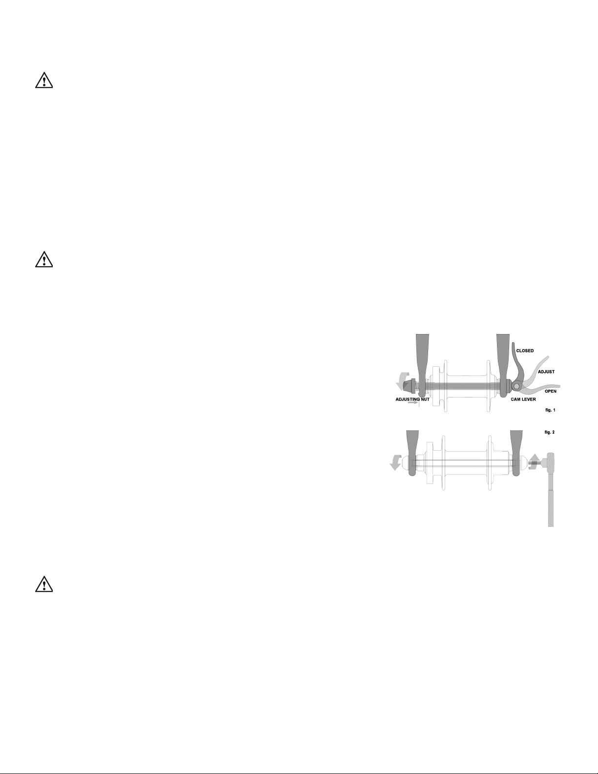
WTB wheels with LaserDisc Lite hubs are secured to the bike frame
and fork with an over-center cam action mechanism, often called a Quick
Release (fig. 1). The WTB LaserDiscXC and LaserDisc Trail 29er are
also available with a single speed rear wheel using the LaserDisc Single
Duty rear hub which can be secured with either an optional Quick
Release or with the supplied hex key cap bolts which are threaded into
the hollow hub axle, called a Bolt-On system (fig.2). WTB wheels which
use a LaserDisc Super Duty hub are secured with through-axles
supplied by the frame or fork manufacturer. To install or remove a
wheel with a WTB LaserDisc Super Duty hub, carefully follow the
frame or fork manufacturer’s instruction for that model throughaxle fitting.
a. Over-center cam action hubs
Most bicycles have front forks which utilize a secondary wheel
retention device molded, cast or machined into the outer faces of the front fork dropouts to reduce the risk of
the wheel disengaging from the fork if the wheel is incorrectly secured. Secondary retention devices are not a
substitute for correctly securing your front wheel.
WARNING:
Do not remove or disable the secondary retention device. As its name implies, it
serves as a back-up for a critical adjustment. If the wheel is not secured correctly, the secondary
retention device can reduce the risk of the wheel disengaging from the fork. Secondary retention
devices are not a substitute for correctly securing your wheel. Failure to properly secure the wheel
can cause the wheel to wobble or disengage, which could cause you to lose control and fall.
(1) Adjusting the over-center cam action mechanism (fig. 1)
The wheel hub is clamped in place by the force of the over-center cam pushing against one dropout and
pulling the tension adjusting nut, by way of the skewer, which runs through the hollow axle, against the other

dropout. The amount of clamping force is controlled by the tension adjusting nut. Turning the tension adjusting
nut clockwise while keeping the open cam lever from rotating increases clamping force; turning it counterclockwise while keeping the open cam lever from rotating reduces clamping force. Less than half a turn of the
tension adjusting nut can make the difference between safe clamping force and unsafe clamping force.
WARNING: The full force of the cam action is needed to clamp the wheel securely. Holding the nut
with one hand and turning the lever like a wing nut with the other hand until everything is as tight as
you can get it will not clamp a cam action wheel safely in the dropouts.
b. Installing a WTB Front Wheel with over-center cam action quick release
CAUTION: Be careful not to damage the disc, caliper or brake pads when re-inserting the disc into
the caliper. Never activate a disc brake’s control lever unless the disc is correctly inserted in the
caliper.
(1) Move the cam lever so that it curves away from the wheel (fig.1). This is the OPEN position.
(2) With the steering fork facing forward, insert the wheel between the fork blades so that the axle seats
firmly at the top of the fork dropouts. The cam lever should be on rider’s left side of the bicycle (fig. 1).
(3) Holding the cam lever in the ADJUST position with your right hand, tighten the tension adjusting nut with
your left hand until it is finger tight against the fork dropout (fig. 1).
(4) While pushing the wheel firmly to the top of the slots in the fork dropouts, and at the same time centering
the wheel rim in the fork, move the cam lever upwards and swing it into the CLOSED position (fig. 1). The lever
should now be parallel to the fork blade and curved toward the wheel. To apply enough clamping force, you
should have to wrap your fingers around the fork blade for leverage, and the lever should leave a clear imprint
in the palm of your hand.
NOTE: If the lever cannot be pushed all the way to a position parallel to the fork blade, return the lever to the
OPEN position. Then turn the tension adjusting nut counterclockwise one-quarter turn and try tightening the
lever again.
WARNING:
Securely clamping the wheel with a cam action retention device takes considerable
force. If you can fully close the cam lever without wrapping your fingers around the fork blade for
leverage, the lever does not leave a clear imprint in the palm of your hand, and the serrations on the
wheel fastener do not emboss the surfaces of the dropouts, the tension is insufficient. Open the lever;
turn the tension adjusting nut clockwise a quarter turn; then try again.
(5) Spin the wheel to make sure that it is centered in the frame and clears the brake pads; then squeeze the
brake lever and make sure that the brakes are operating correctly.
c. Removing a WTB Front Wheel with over-center cam action quick release
CAUTION: Disc rotors have sharp edges, and both rotor and caliper can get very hot during use.
Exercise care in touching the rotor or caliper.
(1) Move the cam lever from the locked or CLOSED position to the OPEN position (fig. 1).
(2) Loosen the tension adjusting nut enough to allow removing the wheel from the fork dropouts. You may
 Loading...