

Page 1

19
W&T
RS232 Multi Computer Adapter
Subject to error and alteration
W&T
Manual
RS232 Multi Computer Adapter
Release 1.2
Model 85603
Page 2

20
W&T
RS232 Multi Computer Adapter
© 10/2006 by Wiesemann & Theis GmbH
Subject to error and alteration:
Since it is possible that we make mistakes, you mustn’t use
any of our statements without verification. Please, inform us
of any error or misunderstanding you come about, so we can
identify and eliminate it as soon as possible.
Carry out your work on or with W&T products only to the
extent that they are described here and after you have completely read and understood the manual or guide. We are not
liable for unauthorized repairs or tampering. When in doubt,
check first with us or with your dealer.
Page 3

21
W&T
RS232 Multi Computer Adapter
Subject to error and alteration
The W&T RS232 Multi Computer Adapter model 85603 permits automatically controlled, bi-directional connection of
two data sources to one peripheral device.
With this unit two PCs, a serial printer, a plotter, a portable
scanner or a card reader for example can be shared without
requiring manual intervention to switch them: automatic selection is on the first come, first served principle.
The interfaces of the Multi Computer Adapter can be
configured independently of each other, so that converting
the baud rate, data format and handshake procedure is no
problem.
Additional information about W&T products and new developments can be found on the Internet at
http://www.wut.de
or are available in the e-mail infograms offered by the W&T
Interface Club, which you can sign up for at the W&T homepage.
Page 4

22
W&T
RS232 Multi Computer Adapter
Contents
Function ............................................................................23
Supply voltage ...................................................................23
Mechanical features and enclosure..................................... 24
Wiring assignments ........................................................... 24
Display and control elements ............................................. 26
Configuring the serial ports ...............................................27
Serial format ......................................................................28
Handshake procedure ........................................................28
Setting the format - DIL switches ........................................29
Modes ............................................................................... 30
Manual mode..................................................................... 30
Standard mode ..................................................................30
Transparent mode ............................................................. 30
Setting the modes.............................................................. 31
Diagnostic functions ..........................................................32
Settings dump ................................................................... 32
Connection example ..........................................................34
Technical Data ................................................................... 35
Declaration of Conformity .................................................. 36
Page 5

23
W&T
RS232 Multi Computer Adapter
Subject to error and alteration
RS232 Multi Computer Adapter, Model 85603
The W&T RS232 Multi Computer Adapter 85603 permits a
bi-directional connection of two serial data sources to a
peripheral device. Automatic switching between the two
senders is done on a time-controlled basis: The data sender
that wants first to output something automatically blocks the
outputs from the other source. If the data sender implements
a pause, both inputs are again ready to receive after a
configurable timeout time. Two LEDs on the front panel of
the switch indicate which of the two input channels is
currently active.
Supply voltage
The supply voltage for the T-switch is provided by an
integrated switched-mode power supply. This features a
variable input voltage range and allows the T-switch to be
powered using the AC adapter provided or alternately by any
AC or DC voltage between 12 and 24V. The supply connection is reverse polarity protected and is made using the
included plug-in screw terminal.
Important: When powering the T-switch externally you
must ensure that the supply voltage used is potentialfree. Voltage sources with a ground reference can
damage the T-switch and/or the connected serial devices.
We therefore recommend using the power supply
included in the scope of delivery.
1
Page 6
24
W&T
RS232 Multi Computer Adapter
Mechanical features and enclosure
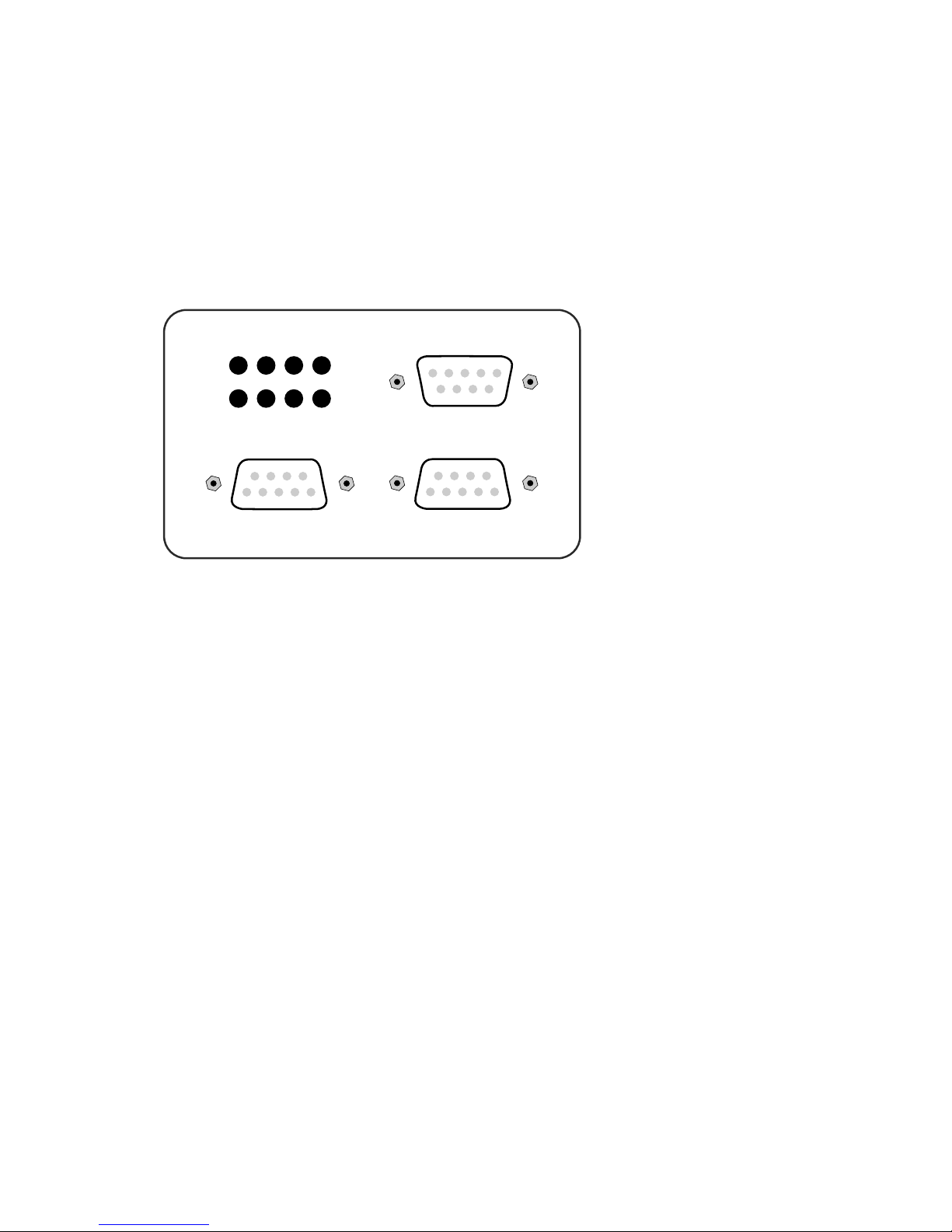
The T-switch comes with three 9-pin RS232 ports and is
integrated into a 45mm wide plastic housing for mounting
on standard rails conformal with DIN EN 50022-35.
Port A Port B
Port C
Pwr Err A B
Clr Dump
Configuring the serial ports and T-switch operating
modes requires opening the housing of the device. For
this purpose it is advantageous to screw a SUB-D plug
with body to one port on the T-switch and use the
attached plug to assist in pulling off the housing cover.
Wiring assignments
The RS232 ports A and B are implemented as SUB-D female
connectors with DCE pin functions, and port C as a SUB-D
male connector with DTE pin functions. This design ensures
that the T-switch can be wired into the majority of
applications with standard 1:1 cables. In addition, this pin
configuration make installation and startup easier, since the
data transfer can be tested first without involving the
T-switch by simply connecting the cables together.
1
Page 7
25
W&T
RS232 Multi Computer Adapter
Subject to error and alteration
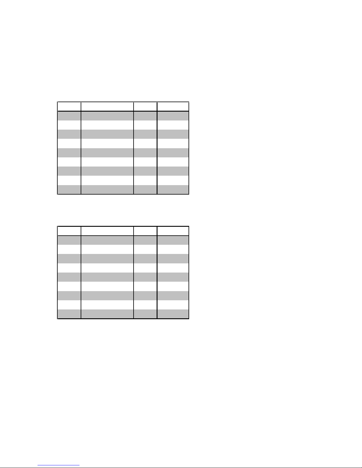
The pinout for the individual ports can be found in the following tables.
RS232 input Port A and B with DCE pin functions:
Pin# Function Signal Direction
1 always "on" DCD output
2 data out RxD output
3 data in TxD input
4 handshake in DTR input
5 signal GND GND GND
6 handshake out DSR output
7 not connected RTS input
8 handshake out CTS output
9 always "off" RI output
RS232 output Port C with DTE pin functions:
Pin# Function Signal Direction
1 not connected DCD input
2 data in RxD input
3 data out TxD output
4 handshake out DTR output
5 signal GND GND GND
6 not connected DSR input
7 always "on" RTS output
8 handshake in CTS input
9 not connected RI input
Page 8

26
W&T
RS232 Multi Computer Adapter
Display and control elements
The device uses four LEDs, a green „Power“ for indicating
correct supply voltage and the LEDs marked „A“ and „B“ to
indicate which input channel is active.
The LED marked „Error“ indicates the presence of parity or
framing errors in running data traffic and can only be
cleared explicitly by pressing the „Clear“ key. The „Clear“ key
resets the T-switch and deletes all internal data and error
memories.
Pressing the „Dump“ key when the device is turned on
outputs the current setting of the T-switch on whichever
serial port has been selected using the DIL switches.
Additional information about this function can be found in
the section Diagnostic functions > Setting-dump.
Page 9
27
W&T
RS232 Multi Computer Adapter
Subject to error and alteration
Configuring the serial ports
All three ports on the T-switch can be configured for
transmission rate, data format and handshake procedure
completely independently of each other. This feature allows
you to connect the T-switch to terminal devices which use
different serial data formats.
The modular construction of the T-switch allows you to
incorporate other interface modules to convert the interface
type within the device. Especially when larger quantities are
involved changing over the T-switch with other interface
modules represents an economical alternative to the
external converters otherwise commonly used. Please contact
us with any requirements for special versions of the T-switch.
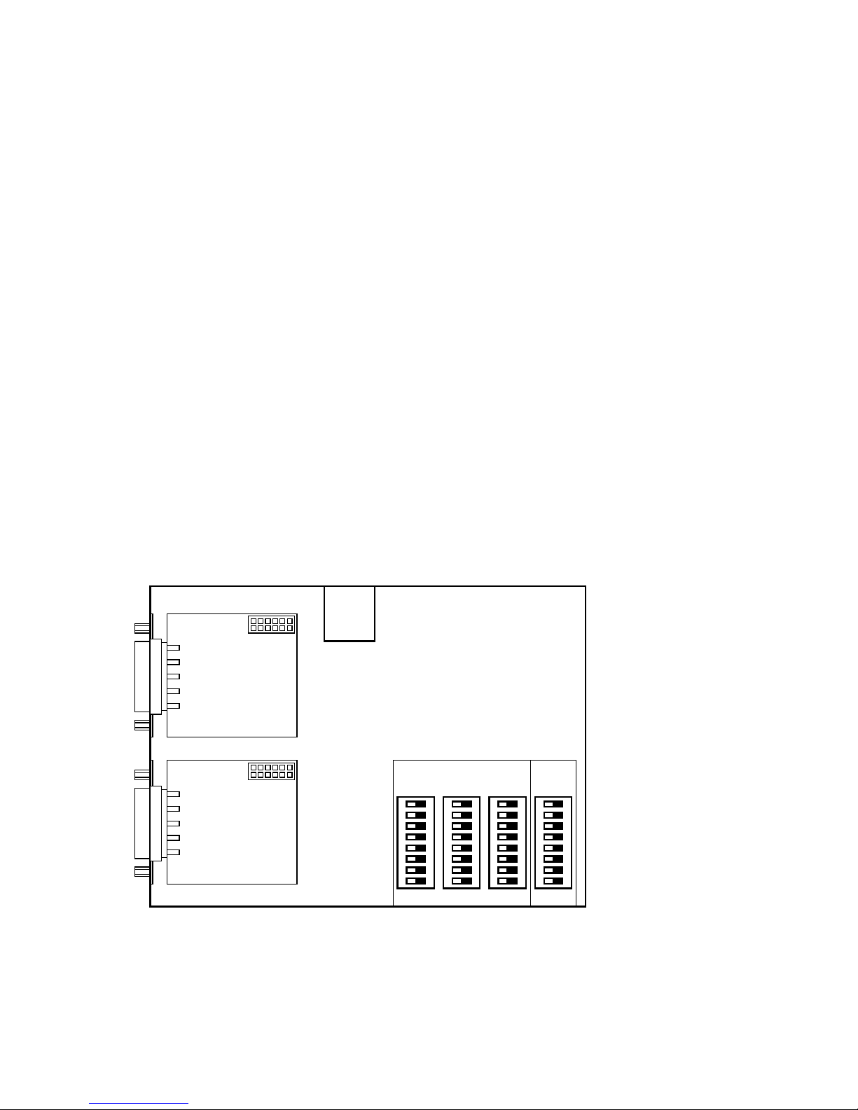
You set the serial parameters using three DIL switch banks
SW1..SW3 inside the device. The position and arrangement of
the DIL switch banks with respect to the corresponding port
can be seen in the following sketch.
SW1 SW2 SW3 SW4
Serial Port Settings
Port A Port B Port C
Operat.
Mode
Port B
Port A
Page 10

28
W&T
RS232 Multi Computer Adapter
Serial format
Baud rate, number of data bits and any parity bit which may
be used can be configured separately for each port on the
T-switch, so that the format can be adapted to any connected
terminal device.
Handshake procedure
All serial ports on the T-switch can be set to hardware
handshake or XON/XOFF handshake independently of each
other. Operating the T-switch with no handshake is not
recommended.
When one of the internal buffers in the T-switch is nearly
filled with data, an XOFF code (13H) is output on the
corresponding port and for the next received character the
hardware handshake output is set to ‚Block‘ (negative level).
Once the buffer has been emptied again, an XON code (11H)
is output and the hardware handshake output is set to
‚Enable‘ (positive level).
If the T-switch receives an XOFF code or detects a block level
(negative level) on the hardware handshake input, it stops
sending data on the corresponding port no later than one
byte after this state is detected. If the T-switch receives an
XON code or detects an enable level (positive level) on the
hardware handshake input, it resumes sending data.
The XON and XOFF codes are used only for the handshake;
these codes are not data and are also not allowed to be
contained in the user data. If a hardware handshake is used
however and the T-switch is correspondingly configured, the
XON and XOFF codes are treated as normal data.
When hardware handshake inputs are open or improperly
wired, the T-switch may send no data on the affected port.
If you use only software handshake and configure the
T-switch accordingly, this problem will of course not occur.
Page 11
29
W&T
RS232 Multi Computer Adapter
Subject to error and alteration
Setting the format - DIL switches
The DIL switch banks SW1, SW2 and SW3 have the same
scope of functions for all three ports: the individual switches
determine the transmission speed, the number of data bits,
the parity and the handshake procedure of the respective
port. The function of the individual switches can be seen in
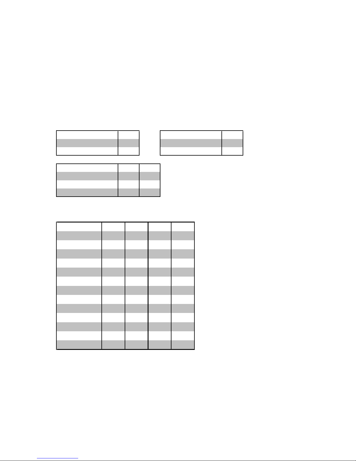
the following tables:
handshake
S1
data bit
S6
hardware handshake
off
7 data bit
off
software handshake
ON
8 data bit
ON
parity
S7 S8
no parity
X off
odd parity
off ON
even parity
ON ON
baudrate S2 S3 S4 S5
150 Baud off off off off
300 Baud ON off off off
600 Baud off ON off off
1200 Baud ON ON off off
2400 Baud off off ON off
4800 Baud ON off ON off
9600 Baud off ON ON off
19200 Baud ON ON ON off
38400 Baud off off off ON
57600 Baud ON off off ON
64000 Baud off ON off ON
76800 Baud ON ON off ON
115200 Baud off off ON ON
Page 12

30
W&T
RS232 Multi Computer Adapter
Modes
The RS232 Multi Computer Adapter model 85603 offers
two operating modes, which are described in the following.
In all operating modes two LEDs on the front panel of the
Multi Computer Adapter are used to indicate which of the
two available data paths is currently active.
A character-activated path between Port A and C or Port B
and C supports bi-directional data transfer between the
respective connected ports. The return direction from Port C
to A or Port C to B is however not enabled until the data
sender on Port A or B has provided for opening of the
channel. If neither of the two paths is activated, any data
arriving at Port C are rejected.
Manual mode
The simplest of all operating modes enables manual toggling
of the bi-directional connection between Port A and Port C or
between Port B and Port C.
Pressing the key below LED A opens path Port A <> Port C,
whereas pressing the key below LED B activates the path
Port B <> Port C. After the selector switch is reset the Port A
<> Port C channel is always active. LEDs A and B indicate
which channel is active.
The selector switch uses a handshake signal ir an XIFF
character to automatically block data flow on the non-active
channel.
Standard mode
In this mode switching between both data sources is
automatic on a time basis: the data sender that wants to
send something first uses a handshake stop signal or XOFF
character generated by the T-switch to automatically block
sending from the other source. If the first data sender inserts
a pause, then the second input is again ready to receive
after a settable switching time. The multi-computer adapter
automatically controls the data flow in this mode using the
handshake procedure set on the respective port.
Page 13

31
W&T
RS232 Multi Computer Adapter
Subject to error and alteration
Transparent mode
The data sender that wants to send something first is
immediately connected to the serial terminal device. All data
received on the other input of the T-switch are rejected as
long as the terminal device is connected to the first data
sender. Two conditions must be met in order to enable the
second input:
- The first data source has sent no more data since a
settable switching time.
- No more data have been received on the second input
since a likewise configurable timeout time.
This mechanism prevents the input from being activated in
the middle of a protocol block and thereby a fragmented
data record from reaching the receiver.
In this mode the Multi Computer Adapter supports only the
two data lines RxD and TxD. The T-switch does not interfere
in the data flow in this mode, but rather transparently
passes the received data from the sender to the respective
receiver. The terminal devices themselves must provide for
any required control of the data flow.
Setting the modes
The two modes of the device are selected and configured
using the DIL switch bank SW4. In addition to selecting the
operating mode, the switchover time for both mode types
can be set in fixed increments of 5, 15, 30 and 120 seconds.
For transparent mode you can also configure the timeout in
steps of 0, 30, 90 and 500 ms.
Page 14
32
W&T
RS232 Multi Computer Adapter
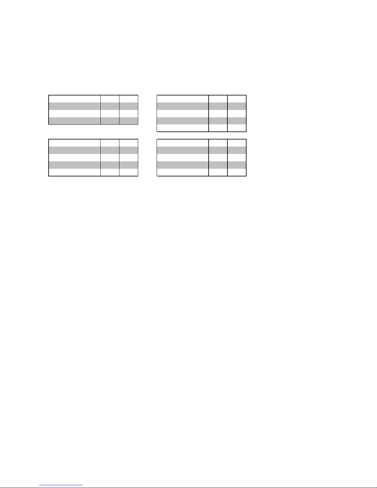
The function of the individual DIL switches in switch bank
SW4 is shown in the following table:
Operating modes S1 S2 Dump Output
S3 S4
Manual mode off off Port A
off off
Standard mode ON off Port B
ON off
Transparent mode off ON Port C
off ON
All ports
ON ON
Switching time
S5 S6
Timeout
S7 S8
5 seconds
off off
0 milliseconds
off off
15 seconds
ON off
30 milliseconds
ON off
30 seconds
off ON
90 milliseconds
off ON
120 seconds
ON ON
500 milliseconds
ON ON
Diagnostic functions
Starting up an RS232 port is often accompanied by
difficulties, since both the pin assignments as well as the
transmission parameters need to agree in order to enable
errorless data transmission.
The RS232 Multi Computer Adapter 85603 has a settings
dump function integrated that allows you to check the
configuration, which can be quite useful during installation.
Settings dump
As a first test the settings dump integrated in the T-switch
can be used to automatically generate a text which shows all
the programmed settings in the 85603.
The settings dump has multiple functions:
: Testing the data and ground line connection
: Testing the transmission parameters
: Concise output of all settings
: Handshake test for data output from the 85603
Page 15

33
W&T
RS232 Multi Computer Adapter
Subject to error and alteration
To be able to generate the settings dump even under
improper handshake conditions, the dump is even output if
the port is blocked, though at a very slow speed. This means:
: Handshake enabled r Fast dump output
: Handshake blocked r Slow dump output
Hold down the „Dump“ key and then connect the T-switch to
its power supply. After releasing the key the port set on the
DIL switches SW4.3 and SW4.4 generates the following
output:
PU 40,6000;;SI 0.2,0.3;DT
LB
LB RS232 MULTI COMPUTER ADAPTER, 0MBYTE
LB VERSION 1.x
LB TRANSPARENT MODE (TIMEOUT MODE)
LB
LB PORT A: BAUD 9600
LB DATA 8
LB PARITY NO
LB
LB HANDSHAKE HARD
LB
LB PORT B: BAUD 9600
LB DATA 8
LB PARITY NO
LB
LB HANDSHAKE HARD
LB
LB PORT C: BAUD 9600
LB DATA 8
LB PARITY NO
LB
LB HANDSHAKE HARD
LB
Page 16
34
W&T
RS232 Multi Computer Adapter
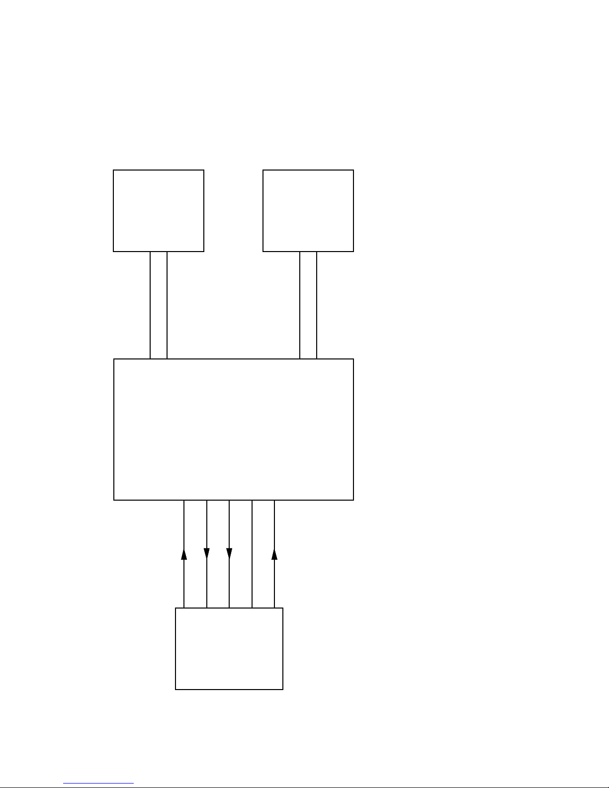
Connection example
Two computers share a peripheral device using a hardware
handshake connection
Extension cable
Extension cable
PC 2
RS232
COM port
PC 1
RS232
COM port
Port A
9-pin female
connector
Port B
(9-pin female
connector)
RS232 Multi
Computer Adapter, #85603
Port C
(9-pin male
connector)
Peripheral
device with
DTE pinout
23458
2(3) 3(2) 5(8) 7(5) 20(4)
Data In
Data Out
Hands. Out
Hands. In
Signal GND
TxD
RxD
CTS
GND
DTR
DB25 (DB9)
9-pin male
connector
9-pin male
connector
Page 17

35
W&T
RS232 Multi Computer Adapter
Subject to error and alteration
Technical Data
Serial ports: 3x RS232, all ports
independently configurable
RS232 inputs Port A, B: 9-pin SUB-D female connectors
with DCE pin functions
RS232 output Port C: 9-pin SUB-D male connector
with DTE pin functions
ESD compatibility: up to15kV per IEC 801-2, Level 4
Baud rate: 150 .. 115.200 baud
Data format: 7, 8 data bits,
No, Even, Odd Parity
Handshake: Optional hardware or
XON-/XOFF handshake
Supported signals: RxD, TxD, CTS, DTR
Operating modes: Standard and transparent mode
Switchover time: Settable switchover time of 5, 15,
30, 120 seconds
(other values on request)
Supply voltage: AC adapter included or
potential-free 12-24V AC/DC
No-load current: typ. 25 mA @24V DC
Ambient temperature: Storage: -40..+70°C
Operating: 0..+60°C with
external 24V supply
Housing / Dimensions: Plastic housing for standard rail
mount per DIN EN 50022-35,
105 x 75 x 45mm
Weight: approx. 500g incl. power supply
Scope of delivery: RS232 Multi Computer Adapter,
Model 85603
AC adapter for office use
Page 18
36
W&T
RS232 Multi Computer Adapter
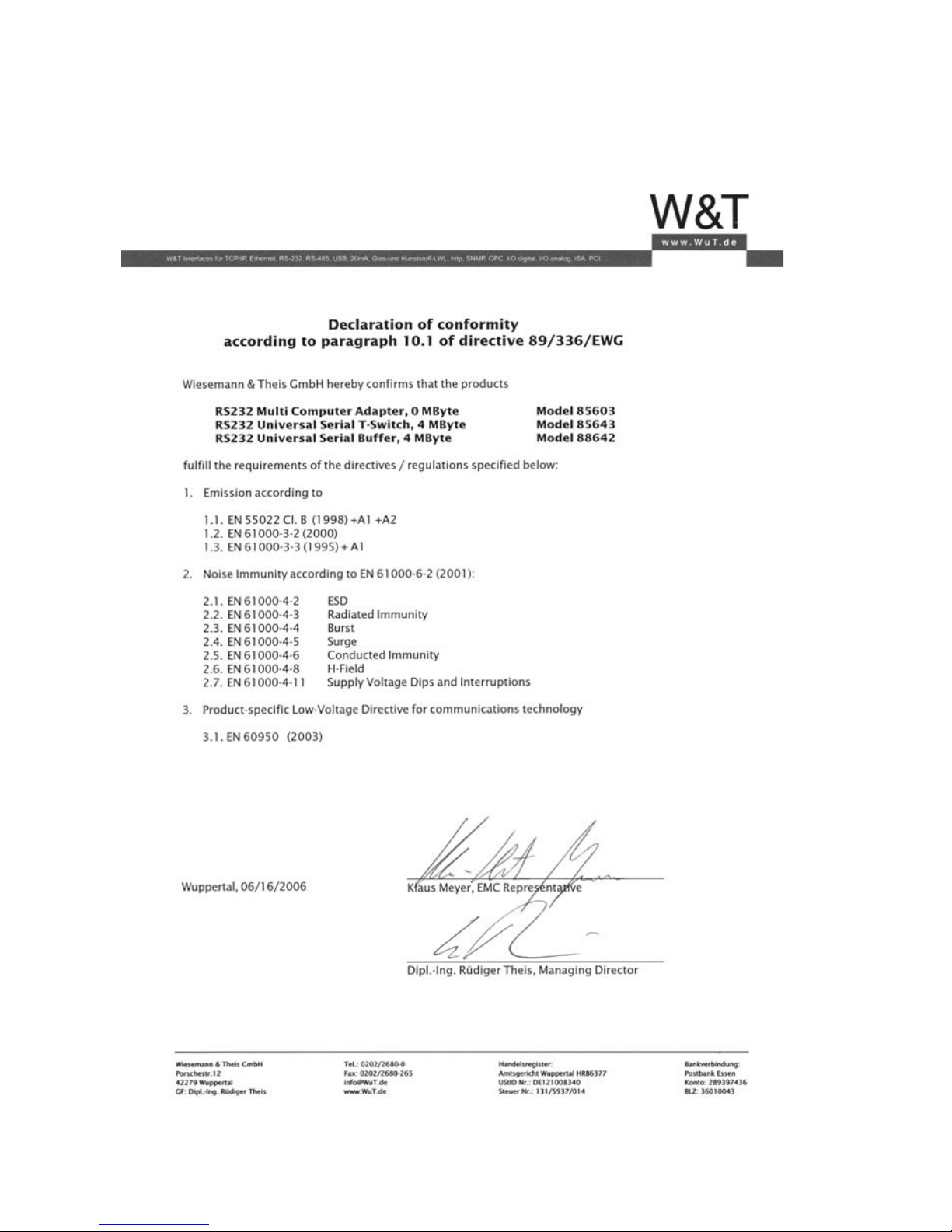
Declaration of Conformity
 Loading...