

Page 1

W&T
Handbuch
RS232 Battery Buffer, 4 MByte
Typ RS232 Battery Buffer,
4 MByte
Modell #88241
Release DE 1.0, 04/2008
Page 2

W&T
© 04/08, Wiesemann & Theis GmbH
Irrtum und Änderung vorbehalten:
Da wir Fehler machen können, darf keine unserer Aussagen
ungeprüft verwendet werden. Bitte melden Sie uns alle Ihnen
bekannt gewordenen Irrtümer oder Missverständlichkeiten,
damit wir diese so schnell wie möglich erkennen und beseitigen können.
Führen Sie Arbeiten an bzw. mit W&T Produkten nur aus, wenn
sie hier beschrieben sind und Sie die Anleitung
vollständig gelesen und verstanden haben. Eigenmächtiges
Handeln kann Gefahren verursachen. Wir haften nicht für die
Folgen eigenmächtigen Handelns. Fragen Sie im Zweifel
lieber noch einmal bei uns bzw. Ihrem Händler nach!
Page 3

W&T
Page 4

W&T
Inhalt
1 Einführung ........................................................................ 6
2 Spannungsversorgung ....................................................... 7
2.1 Batteriebetrieb ................................................................ 7
2.2 Netzteilbetrieb ................................................................ 8
3 Mechanik und Gehäuse ...................................................... 9
4 Anzeige- und Bedienelemente des Buffers .......................... 10
4.1 LEDs ............................................................................ 10
4.2 Tasten .......................................................................... 10
4.3 Funktionsübersicht ....................................................... 11
5 Aufzeichnen serieller Daten ..............................................12
5.1 Daten anfügen .............................................................. 12
5.2 Speicherinhalt überschreiben ......................................... 12
5.3 Speicherinhalt löschen .................................................. 13
6 Wiedergabe gespeicherter Daten ....................................... 14
7 RS232-Schnittstelle .......................................................... 15
7.1 Anschlussbelegung ...................................................... 15
7.2 Anschlussbeispiel .........................................................16
7.3 Handshake-Verfahren .................................................... 16
7.4 Einstellung der DIL-Schalter ........................................... 18
8 Inbetriebnahme ............................................................... 19
8.1 Einstellungs-Dump ........................................................ 19
8.2 Einstellungs-Dump ausgeben ........................................ 20
9 Technische Daten ............................................................21
Page 5

W&T
Page 6
6
W&T
RS232 Battery Buffer, 4 MByte
1 Einführung
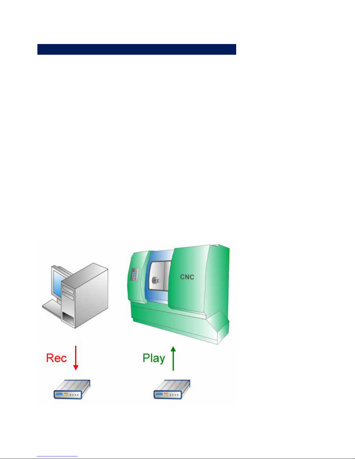
Der W&T Battery Buffer ermöglicht die nichtflüchtige Speicherung serieller Daten bis zu einer Maximalgröße von 4MByte. Die
Daten können mit Hilfe des Buffers von einem Datensender zu
einem Empfänger transportiert werden, ohne dass zwischen den
Endgeräten eine Kabelverbindung existieren muss. Der Buffer
verhält sich dabei wie die hinlänglich bekannten USB-Sticks mit dem Unterschied, dass der Buffer über eine RS232-Schnittstelle zum Senden und Empfangen der Daten und über Tasten
und LEDs für eine lokale Bedienung verfügt.
Mit einer Batterie oder einem Akkumulators des Typs AA arbeitet der Buffer auch ohne externe Spannungsversorung.
Der interne Flashspeicher sorgt dafür, dass die gespeicherten
Daten auch ohne permanente Spannungsversorgung jederzeit
zur Verfügung stehen. Im RS232 Battery Buffer kommen
Speicherbausteine zum Einsatz, die eine typische Lebensdauer
von 1.000.000 Schreibzyklen pro Speicherzelle besitzen.
Datentransport mit dem RS232 Battery Buffer
Page 7

7
W&T
RS232 Battery Buffer, 4 MByte
2 Spannungsversorgung
Der Battery Buffer kann auf zwei Arten mit der benötigten
Betriebsspannung versorgt werden:
. eine interne Batterie des Typs AA
. externes 5V-Steckernetzteil
Der Betrieb des Buffers mit einem Steckernetzteil bei gleichzeitig eingesetzter Batterie ist ebenfalls möglich. Die Batterieversorgung ist dann deaktiviert. Solange ein Steckernetzteil im
Einsatz ist, wird der Batterie keine Leistung entnommen.
Wechseln Sie nicht im laufenden Betrieb die Quel-
1 le für die Betriebsspannung. Der Buffer kann sich dabei
ausschalten.
2.1 Batteriebetrieb
Für den Batteriebetrieb des Battery Buffers ist eine Batterie des
Typs AA erforderlich.
Verwenden Sie zur Versorgung des Buffers den im
1 Lieferumfang enthaltenen Akkumulator, laden Sie die-
sen unbedingt vor der ersten Inbetriebnahme mit einem
geeingneten Ladegerät auf!
Arbeitet das Gerät im Batteriebetrieb, blinkt die Power-LED in der
Frontblende zyklisch. Sinkt die Batteriespannung auf ein kritisches Niveau, erhöht sich die Blinkfrequenz. Tauschen Sie die
Batterie dann umgehend aus.
Zum Wechseln der Batterie drehen Sie die Verschlusskappe des
Batteriefachs auf der Rückseite des Gerätes um 90° gegen den
Uhrzeigersinn. Entnehmen Sie die alte Batterie und stecken Sie
eine neue Batterie mit dem Minuspol voran in das Batteriefach.
Setzen Sie den Batteriefachdeckel wieder ein und verriegeln Sie
diesen durch Drehen um 90° im Uhrzeigersinn.
Page 8

8
W&T
RS232 Battery Buffer, 4 MByte
Wird der Buffer im Batteriebetrieb betrieben und befindet sich
für 15 Minuten ungenutzt im Ruhezustand, schaltet sich das
Gerät selbständig ab.
Akkumulatoren werden bei angeschlossenem Netzteil
1 nicht im Gerät geladen. Verwenden Sie zum Laden von
Akkus ein entsprechendes Ladegerät.
2.2 Netzteilbetrieb
Das mitgelieferte Steckernetzteil wird mit dem 5,5mm Hohlstecker in die entsprechende Buchse auf der Rückseite des
Buffers gesteckt.
Für die externe Versorgung ist eine Spannung von 5V +/-10%
erforderlich. Der Minuspol ist auf dem inneren Kontakt des
Hohlsteckers aufgelegt, der Pluspol außen.
Wird der Buffer extern versorgt, leuchtet die Power-LED permanent.
Es wird empfohlen den Battery Buffer lediglich mit
1 Netzteilen der Firma W&T zu betreiben und auf den Ein-
satz von Netzteilen von anderen Herstellern zu verzichten.
Page 9
9
W&T
RS232 Battery Buffer, 4 MByte
3 Mechanik und Gehäuse
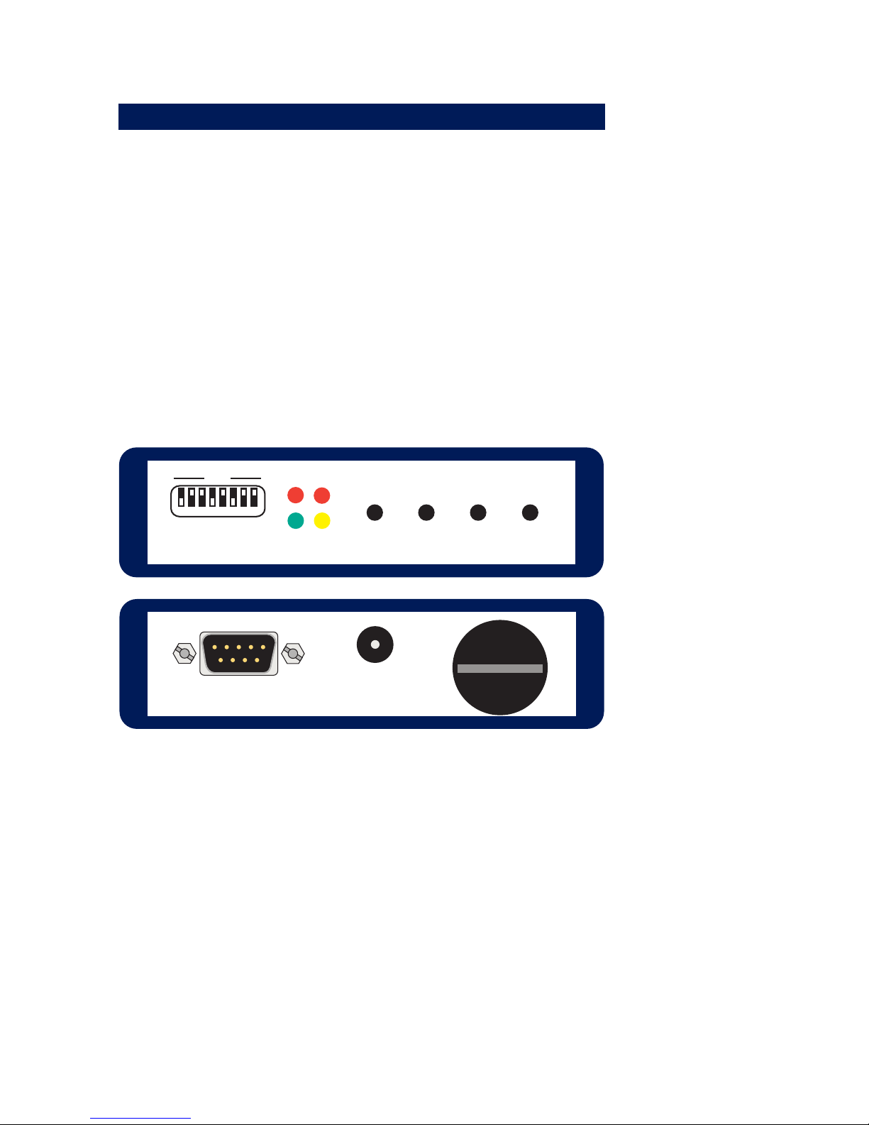
Der Buffer verfügt über eine 9-polige RS232-Schnittstelle an der
Geräterückseite, über die Daten eingespielt und ausgelesen werden können.
Durch eine Öffnung an der Gerätefront sind die DIL-Schalter zugänglich, über die das serielle Format eingestellt werden kann.
Des Weiteren befinden sich sämtliche Taster und LEDs, die zum
Bedienen des Gerätes erfoderlich sind, auf der Vorderseite des
Buffers.
Der Buffer ist in ein robustes Metallgehäuse mit den Maßen 115
x 90 x 34mm integriert.
Power
Rec
Error
Play
Rec Play
OffOn
OFF
12345678
Vorder- und Rückansicht des RS232 Battery Buffers
Page 10

10
W&T
RS232 Battery Buffer, 4 MByte
4 Anzeige- und Bedienelemente des Buffers
4.1 LEDs
Der Buffer verfügt über vier Leuchtdioden. Die gelbe Power-LED
signalisiert die korrekte Spannungsversorgung. Bei konstantem
Leuchten wird das Gerät extern über ein Steckernetzteil mit
Spannung versorgt. Blinkt die LED, erfolgt die Geräteversorgung
über die eingesetzte Batterie.
Die rote Error-LED zeigt das Auftreten von Fehlern (Paritäts-,
Rahmen- oder Überlauffehlern) im laufenden Datenverkehr an.
Die anstehenden Fehler werden beim nächsten Aktivieren des
Play- oder des Rec-Modus automatisch gelöscht.
Die Rec-LED (rot) zeigt an, dass der Buffer gerade Daten von
einem Endgerät empfängt und diese speichert.
Die grüne Play-LED signalisiert, dass gespeicherte Daten gerade über die serielle Schnittstelle des Buffers ausgegeben werden.
4.2 Tasten
Über die On- und die Off-Taste kann der Buffer ein- und ausgeschaltet werden. Die entsprechende Funktion wird nach einem
ca. 1 Sekunde langen Druck auf die Taste ausgelöst. Wird der
Buffer über ein Steckernetzteil mit Spannung versorgt, werden
die Tasten On und Off nicht benötigt. Das Gerät ist dann immer
eingeschaltet und kann nicht abgeschaltet werden.
Über die Play- und die Rec-Taste wird das Aufnehmen und Wiedergeben von seriellen Daten gesteuert.
Die DIL-Schalter ermöglichen das Einstellen des seriellen Formats, mit dem die serielle Schnittstelle auf der Rückseite des
Buffers kommuniziert.
Page 11

11
W&T
RS232 Battery Buffer, 4 MByte
4.3 Funktionsübersicht
Die folgende Tabelle zeigt den Zusammenhang zwischen den
Funktionen, die über die Taster ausgelöst werden können und
die optische Rückmeldung des Buffers über die LEDs.
Funktion Taste(n) Dauer LED(s)
Einschalten
(nur bei
Batteriebetrieb)
On ca. 1s
alle LEDs erst an,
dann aus, dann nur
Power
Ausschalten
(nur bei
Batteriebetrieb)
Off ca. 1s alle LEDs aus
Daten anfügen Rec ca. 2s Rec an
Überschreiben Rec und Play ca. 2s Rec an
Aufnahme beenden Rec sofort Rec aus
Wiedergabe Play ca. 1s Play an
Wiedergabe beenden Play sofort Play aus
Speicher löschen
Rec und Play im
Einschaltmoment
ca. 1s Rec und Play blinken
Einstellungs-Dump
Play im
Einschaltmoment
ca. 1s Rec
Funktionen der Tasten
Page 12

12
W&T
RS232 Battery Buffer, 4 MByte
5 Aufzeichnen serieller Daten
Mit den Tasten Rec bzw. Rec und Play wird der Buffer in den
Aufnahmemodus gebracht, in dem alle über den seriellen Port
empfangenen Daten in den internen Speicher geschrieben werden. Mit einem weiteren Druck auf die Rec-Taste wird der
Aufnahmemodus wieder verlassen und die Aufzeichnung der
Daten beendet.
Das Gesamtvolumen der gespeicherten Daten darf die
Kapazitätsgrenze von 4MByte nicht überschreiten. Bei Erreichen
dieser Grenze wird der Datensender über das eingestellte
Handshakeprotokoll angehalten. Zusätzlich wird das Erreichen
der Maximalkapazität durch Blinken der Error-LED angezeigt.
Während der Buffer in den Aufnahmemodus gebracht wird, dürfen keine Daten an das Gerät gesendet werden. Lediglich Daten, die nach dem Aufleuchten der Rec-LED empfangen werden,
werden im Speicher abgelegt.
5.1 Daten anfügen
Wird die Taste Rec so lange betätigt, bis die rote Rec-LED
permenent zu leuchten beginnt (erforderliche Dauer des
Tastendrucks ca. 2 Sekunden), so werden die anschließend
empfangenen Daten an einen eventuell vorhandenen Speicherinhalt angefügt. Kürzere Tastendrücke auf die Rec-Taste werden sicherheitshalber ignoriert.
Der Empfang von Daten wird durch Blinken der Rec-LED angezeigt.
5.2 Speicherinhalt überschreiben
Werden Rec und Play gleichzeitig betätigt, bis die rote Rec-LED
permanent zu leuchten beginnt (erforderliche Dauer des
Tastendrucks ca. 2 Sekunden), wird ein eventuell vorhandener
Speicherinhalt gelöscht und durch die neu empfangenen Daten
Page 13

13
W&T
RS232 Battery Buffer, 4 MByte
ersetzt. Kürzeres, gleichzeitiges Betätigen der Tastenkombination Rec und Play wird sicherheitshalber ignoriert.
Der Empfang von Daten wird durch Blinken der Rec-LED angezeigt.
5.3 Speicherinhalt löschen
Werden im Einschaltmoment (beim Drücken der On-Taste oder
Einstecken eines Steckernetzteils) die Tasten Rec und Play gedrückt, wird der interne Speicher des Buffers komplett gelöscht.
Die typische Dauer dieses Vorgangs liegt bei ca. 30 Sekunden.
Nachdem der Speicher vollständig gelöscht wurde, startet das
Gerät neu und ist dann wieder betriebsbereit.
Page 14

14
W&T
RS232 Battery Buffer, 4 MByte
6 Wiedergabe gespeicherter Daten
Mit der Taste Play wird der Buffer in den Wiedergabemodus gebracht (erforderliche Dauer des Tastendrucks ca. 2 Sekunden),
in dem alle zuvor gespeicherten Daten ausgegeben werden. Die
Ausgabe der Daten kann beliebig oft wiederholt werden.
Die Datenausgabe wird durch Blinken der Play-LED gekennzeichnet.
Wenn alle Daten ausgegeben sind, erlischt die Play-LED selbständig und der Buffer geht automatisch in den Ruhezustand.
Eine einmal aktivierte Datenausgabe kann jederzeit durch einen
weiteren Druck auf die Play-Taste abgebrochen werden.
Page 15
15
W&T
RS232 Battery Buffer, 4 MByte
7 RS232-Schnittstelle
Der RS232-Anschluss des Buffers ist als SUB-D-Stecker mit DTEBelegung ausgeführt. Durch diese Schnittstellenbelegung ist
gewährleistet, dass der Buffer mit einem Standard Nullmodemkabel nahezu an jedes Endgerät angeschlossen werden kann.
Das Datenformat des seriellen Ports muss selbstverständlich
dem verwendeten Format des Datensenders und Datenempfängers angepasst werden und kann mit Hilfe der von
außen zugänglichen DIL-Schalter eingestellt werden.
7.1 Anschlussbelegung
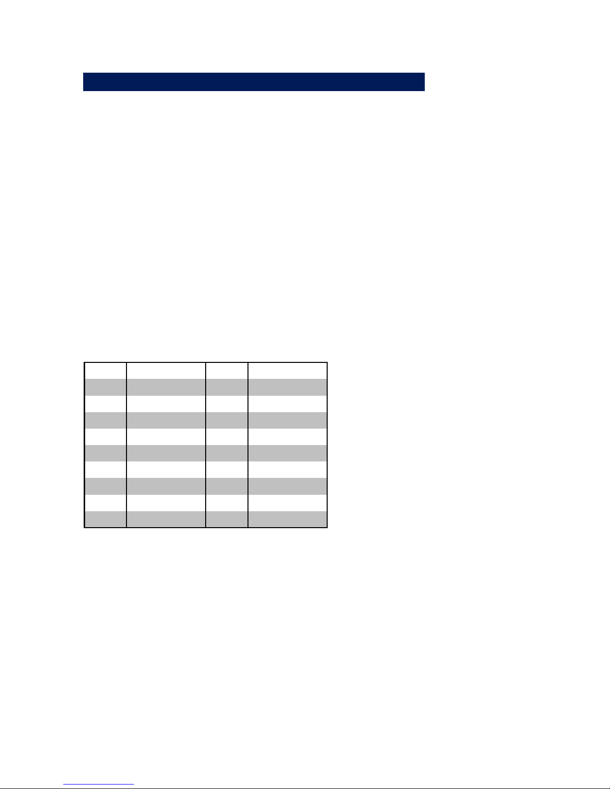
Das Pinout der seriellen Schnittstelle ist in der folgenden Tabelle dargestellt.
Pin# Funktion Signal Richtung
1 unbelegt DCD Eingang
2 Data In RxD Eingang
3 Data Out TxD Ausgang
4 Freigabepegel DTR Ausgang
5 Signalmasse GND ---
6 unbelegt DSR Eingang
7 Handshake Out RTS Ausgang
8 Handshake In CTS Eingang
9 unbelegt RI Eingang
Pinout der integrierten RS232-Schnittstelle
Das Anschlusskabel zwischen Buffer und Peripheriegerät muss
an die Steckerbelegung des Peripheriegerätes angepasst werden. Entsprechende Anschlussbeispiele finden Sie auf der
nächsten Seite.
Page 16
16
W&T
RS232 Battery Buffer, 4 MByte
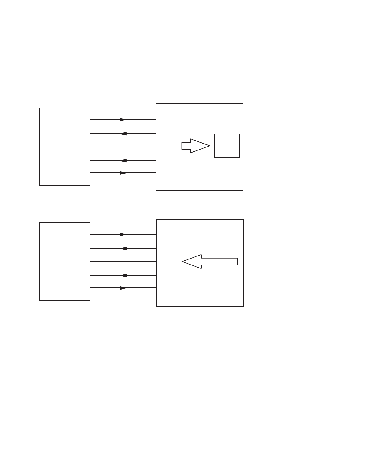
7.2 Anschlussbeispiel
Transport serieller Daten von einem PC zu einem Peripheriegerät mit DCE-Belegung: Aufnahme der Daten vom PC im Rec-Modus, Einspielen der Daten in das Peripheriegerät mit Play.
DB9
PC
2
3
5
8
3
2
5
8
Data In
Data Out
Hands. In
Signal GND
TxD
RxD
GND
CTS
REC
4MByte
Speicher
7
Hands. Out
7
RTS
4MByte Speicher
Peripheriegerät
mit
DCE-Belegung
DB25 (DB9)
PLAY
2
3
5
8
3(2)
2(3)
7(5)
4(7)
Data In
Data Out
Hands. In
Signal GND
TxD
RxD
GND
CTS
7
Hands. Out
5(8)
RTS
RS232 Battery Buffer
RS232 Battery Buffer
Anschlussbeispiel für das Speichern und Wiedergeben von Daten
7.3 Handshake-Verfahren
Die serielle Schnittstelle des Buffers kann wahlweise auf Hardware- oder auf XON-/XOFF-Handshake eingestellt werden. Ein
Betrieb des Buffers ohne Handshake sollte vermieden werden
und kann zu Datenverlusten führen.
Wenn der Buffer fast vollständig mit Daten gefüllt ist, so wird
an der entsprechenden Schnittstelle ein XOFF-Code ausgege-
Page 17

17
W&T
RS232 Battery Buffer, 4 MByte
ben, bzw. beim nächsten empfangenen Zeichen der Ausgang
des Hardware-Handshake-Protokolls auf Sperren gesetzt.
Empfängt der Buffer einen XOFF-Code oder erkennt er auf dem
Hardware-Handshake-Eingang einen Sperrpegel, so stoppt er
die Datensendung spätestens ein Byte nach Erkennen dieses
Zustandes. Empfängt der Buffer einen XON-Code oder erkennt
er am Hardware-Handshake-Eingang einen Freigabepegel, so
setzt er die Datensendung fort.
Die XON- und XOFF-Codes dienen ausschließlich der Flusskontrolle. Sie sind keine Daten und dürfen auch nicht in den
Nutzdaten enthalten sein. Wird dagegen der Hardware-Handshake verwendet und der Buffer entsprechend konfiguriert, so
werden die XON- und XOFF-Codes als normale Daten behandelt.
Bei offenem oder falsch beschaltetem Hardware-Handshake-Eingang sendet der Buffer ggf. keine Daten. Falls Sie SoftwareHandshake verwenden und den Buffer entsprechend konfigurieren, tritt dieses Problem nicht auf.
Page 18
18
W&T
RS232 Battery Buffer, 4 MByte
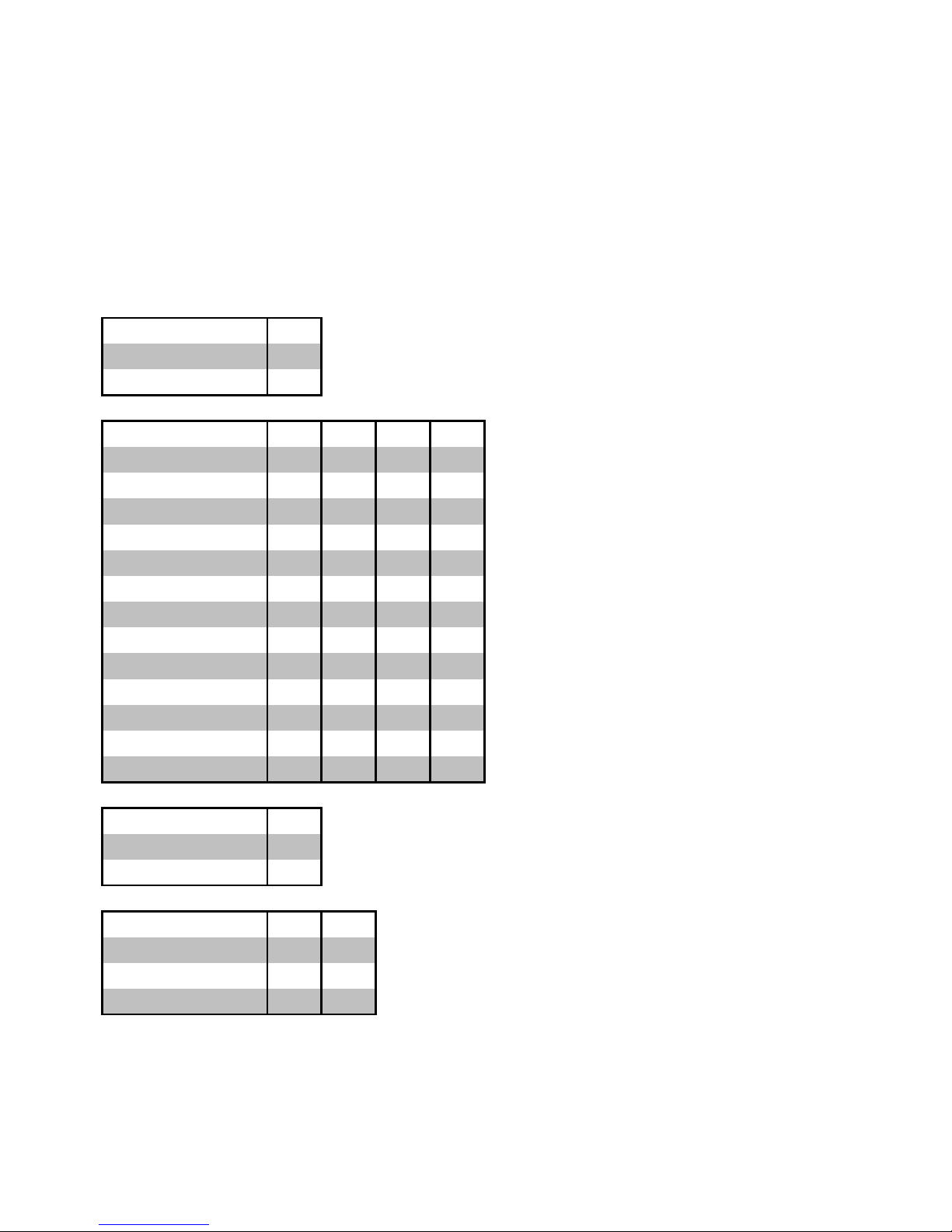
7.4 Einstellung der DIL-Schalter
Die einzelnen Schalter der extern zugänglichen Schalterbank
bestimmen die Übertragungsgeschwindigkeit, die Anzahl der
Datenbits, die verwendete Parität und das Handshake-Verfahren
der Schnittstelle. Die Funktion der einzelnen Schalter ist in der
folgenden Tabelle erläutert.
Handshake S1
Hardware-Handshake off
Software-Handshake ON
Baudrate S2 S3 S4 S5
150 Baud off off off off
300 Baud ON off off off
600 Baud off ON off off
1200 Baud ON ON off off
2400 Baud off off ON off
4800 Baud ON off ON off
9600 Baud off ON ON off
19200 Baud ON ON ON off
38400 Baud off off off ON
57600 Baud ON off off ON
64000 Baud off ON off ON
76800 Baud ON ON off ON
115200 Baud off off ON ON
Datenbits S6
7 Datenbits off
8 Datenbits ON
Parität S7 S8
Keine Parität ON off
Ungerade Parität off ON
Gerade Parität ON ON
Schalterstellungen für serielle Formate
Page 19

19
W&T
RS232 Battery Buffer, 4 MByte
8 Inbetriebnahme
Die Inbetriebnahme einer RS232-Schnittstelle bereitet häufig
Schwierigkeiten, da sowohl die Pinbelegung als auch die
Übertragungsparameter stimmen müssen, um eine fehlerfreie
Datenübertragung zu ermöglichen. Zur Überprüfung der Konfiguration hat der RS232 Battery Buffer mit dem EinstellungsDump eine Funktion integriert, die bei der Installation sehr hilfreich sein kann.
8.1 Einstellungs-Dump
Als erster Test im Zuge der Inbetriebnahme kann der im Buffer
integrierte Einstellungs-Dump dienen, bei dem der Buffer selbständig einen Text generiet, der alle programmierten Einstellungen wiedergibt.
Der Einstellungs-Dump hat mehrere Funktionen:
. Testen des Anschlusses der Daten- und Masseleitung
. Testen der Übertragungsparameter
. Übersichtliche Ausgabe aller Einstellungen
. Handshaketest für den Datenausgang aus dem Gerät
Um auch bei fehlerhaften Handshake-Bedingungen den Einstellungs-Dump erzeugen zu können, wird der Dump bei gesperrter Schnittstelle ebenfalls ausgegeben, jedoch mit einer sehr
niedrigen Geschwindigkeit. Es gilt also:
. Handshake freigegeben: schnelle Ausgabe des Dumps
. Handshake gesperrt: langsame Ausgabe des Dumps
Page 20

20
W&T
RS232 Battery Buffer, 4 MByte
8.2 Einstellungs-Dump ausgeben
Zum Erzeugen des Einstellungs-Dumps, halten Sie die Play-Taste gedrückt und schalten Sie das Gerät durch Verbinden mit einem Steckernetzteil oder durch Drücken des On-Tasters bei
Batteriebetrieb ein. Im Folgenden ist ein Einstellungs-Dump abgebildet, der die Geräteeinstellungen wiedergibt:
PU 40,6000;;SI 0.2,0.3;DT
LB
LB RS232 PORTABLE BUFFER, 4 MBYTE WITH BATTERY
LB VERSION 1.0
LB
LB BAUD 9600
LB DATA 8
LB PARITY NO
LB
LB HANDSHAKE HARD
LB
Page 21

21
W&T
RS232 Battery Buffer, 4 MByte
9 Technische Daten
Serieller Anschluss: 1x RS232 (9-poliger SUB-D-Stecker
mit DTE-Belegung)
ESD-Festigkeit: bis 15kV nach IEC 801-2,Stufe 4
Baudrate: 150..115.200 Baud
Datenformat: 7, 8 Datenbit, No, Even, Odd Parity
Handshake: wahlweise Hardware- oder
XON-/XOFF-Handshake
Unterstützte Signale: RxD, TxD, Handshake In, Hand-
shake Out
Buffergröße: 4 MByte Flash-Speicher
Stromversorgung: mitgeliefertes Steckernetzteil
oder Batterie des Typs AA
Batterielaufzeit: mitgelieferter Akkumulator:
typ. 10h @ 22°C
Umgebungstemperatur: Lagerung: -40..+65°C
Betrieb: 0..+60°C
(abhängig von der verwendeten
Batterie)
Gehäuse/ Abmessungen: Aluminiumgehäuse,
115 x 90 x 34mm
Gewicht: ca. 500g inkl. Netzteil
Lieferumfang: - RS232 Battery Buffer, 4 MByte
- Steckernetzteil für
Büroanwendungen
- Akkumulator (Typ AA) zum netz unabhängigen Betrieb
Page 22

W&T
Page 23

W&T
Manual
RS232 Battery Buffer, 4 MByte
Type RS232 Battery Buffer,
4 MByte
Model #88241
Release US 1.0, 10/2008
Page 24

W&T
© 10/08, Wiesemann & Theis GmbH
Subject to errors and changes:
Since we can make errors, none of our information should be
used without verification. Please inform us of any mistakes or
misunderstandings so that we can detect and eliminate them
as quickly as possible..
Carry out work on and with W&T products only if it is described
here and you have fully read and understood the manual.
Unauthorized actions can result in hazards. We are not liable
for the consequences of unauthorized actions. When in doubt,
please contact us or your dealer first!
Page 25

W&T
Page 26
26
W&T
RS232 Battery Buffer, 4 MByte
1 Introduction
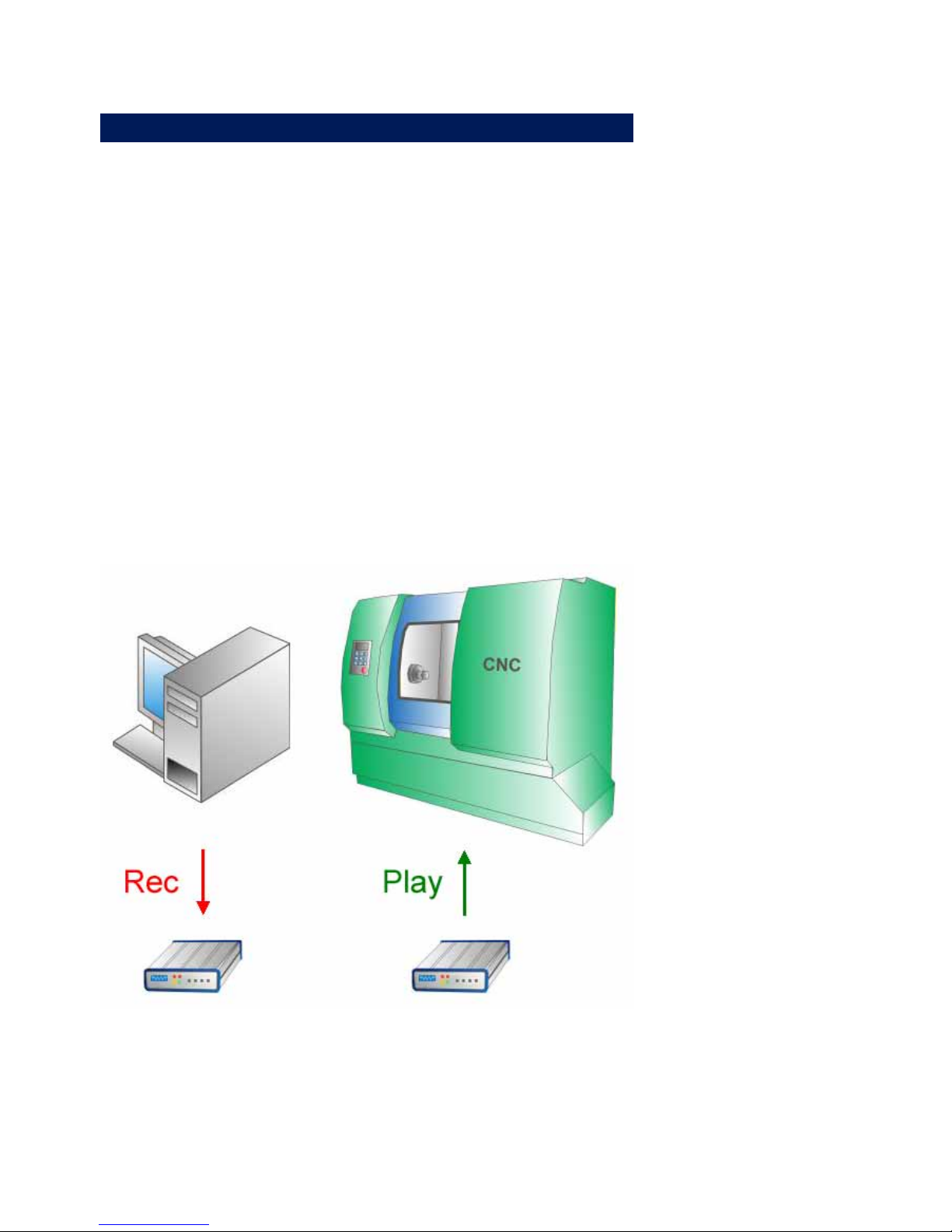
The W&T Battery Buffer enables non-volatile storing of serial
data up to a maximum size of 4MB. The data can be transported
from a data sender to a receiver using the Buffer without
requiring a cable connection between the terminal devices. The
BUffer behaves like a familiar USB stick - with the difference that
the Buffer has an RS232 port for sending and receiving the data
and keys and LEDs for local operation.
The Buffer also functions without an external power supply
when a type AA battery (also rechargeable) is used.
The internal flash memory ensures that the stored data are also
available at any time without use of an external power supply.
The memory chips used in the RS232 Battery Buffer have a
typical useful life of 1,000,000 write cycles per memory cell.
Data transport using the RS232 Battery Buffer
Page 27

27
W&T
RS232 Battery Buffer, 4 MByte
2 Supply Voltage
The Battery Buffer can be powered with the required operating
voltage in one of two ways:
. One type AA internal battery
. External 5V AC adapter
The Buffer can also be operated using an AC adapter with the
AA battery inserted. Battery power is then disabled. No power is
taken from the battery as long as an AC adapter is plugged in.
Do not switch voltage sources while the Buffer is running
1 Otherwise the Buffer may turn off.
2.1 Battery operation
A type AA battery is used for battery operating the Battery
Buffer.
If using the rechargeable battery included with the
1 Buffer,be sure to charge it first using a suitable battery
charger!
While the device is operating in battery mode, the Power LED on
the front panel will flash. If the battery voltage drops below a
critical level, the flashing rate will increase. The battery must
then be replaced as soon as possible.
To replace the battery, turn the cover for the battery
compartment on the back side of the device by 90° counterclockwise. Remove the old battery and insert a new battery into
the compartment with the minus pole facing forward. Replace
the battery compartment cover and lock it by turning it 90°
clockwise.
If the Buffer is operated in battery mode and there is no action
for 15 minutes, the device will shut itself off.
Page 28

28
W&T
RS232 Battery Buffer, 4 MByte
Rechargeable batteries are not charged in the device
1 while the AC adapter is plugged in. Use an appropriate
charger for recharging batteries.
2.2 Power supply operation
The included AC adapter is plugged into the corresponding
jack on the back side of the Buffer using the 5.5mm plug.
A voltage of 5V +/-10% is required for external power. The minus pole is connected to the inner contact of the plug, the plus
pole to the outer.
While the Buffer is being powered externally the Power LED is
continuously on.
It is recommended that the Battery Buffer be powered
1 only by W&T power supplies instead of those of other
manufacturers.
Page 29
29
W&T
RS232 Battery Buffer, 4 MByte
3 Mechanical Features, Housing
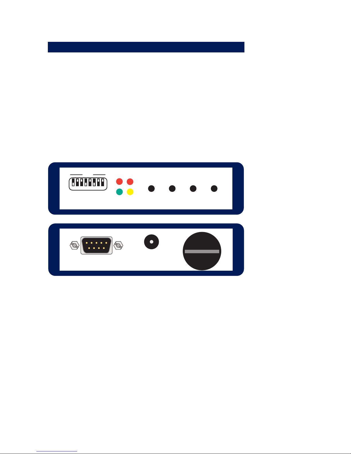
The Buffer has a 9-pin RS232 port on the rear of the unit
thorugh which data are up- and downloaded.
The DIL switches are accessible through an opening on the
front of the unit; these are used to set the serial format. Also
on the front side of the Buffer are all the buttons and LEDs
needed for operating the device.
The Buffer is enclosed in a rugged metal housing 115 x 90 x
34mm.
Power
Rec
Error
Play
Rec Play
OffOn
OFF
12345678
Front and rear view of the RS232 Battery Buffer
Page 30

30
W&T
RS232 Battery Buffer, 4 MByte
4 Display and Operating Elements
4.1 LEDs
The Buffer has four LEDs. The yellow Power LED indicates
correct supply voltage. When continuously on, it means that the
device is being supplied with power from an external AC
adapter. If the LED is flashing, the device is being powered
using the internal battery.
The red Error LED indicates the occurrence of errors (parity,
frame or overflow errors) in data traffic. The errors present are
automatically cleared the next time Play or Rec mode is
enabled.
The Rec LED (red) indicates that the Buffer is currently receiving
data from a terminal device and storing the data.
The green Play LED indicates that stored data are being output
through the serial port of the Buffer.
4.2 Keys
The On- and Off key is used to power the Buffer on and off. The
corresponding function is carried out after holding down the
key for approx. 1 second. If the Buffer is powered from an AC
adapter, the On and Off keys are not needed. The device is
always turned on and cannot be turned off.
The Play- and Rec keys are used to control the recording and
playback of serial data.
The DIL switches allow you to set the serial format which the
serial port on the rear of the Buffer uses for communication.
Page 31
31
W&T
RS232 Battery Buffer, 4 MByte
4.3 Function overview
The following table shows the relationship between the
functions which can be triggered by the buttons and the visual
indication for the Buffer by the LEDs.
Function Key(s) Duration LED(s)
Power on
(only at battery
use)
On approx. 1s
First all LEDs on,
then off, finally only
power on
Power off
(only at battery
use)
Off approx. 1s all LEDs off
Append data Rec approx. 2s Rec on
Overwrite Rec and Play approx. 2s Rec on
Stop recording Rec at once Rec off
Play Play approx. 1s Play on
Stop play Play at once Play off
Clear memory
Rec uand Play while
powering on
approx. 1s Rec and play flashing
Settings-dump
Play while powering
on
approx. 1s Rec
Key functions
Page 32

32
W&T
RS232 Battery Buffer, 4 MByte
5 Recording Serial Data
The Rec and Rec/Play keys are used to set the Buffer to
recording mode, in which all the data received through the
serial port are written to the internal memory. Pressing the Rec
key again exits recording mode and ends the recording of data.
The total volume of stored data may not exceed the capacity
limit of 4MB. When this limit is reached, the data senter is
stopped by the set handshake protocol. In addition, the Error
LED flashes when the maximum capacity is reached.
No data may be sent to the Buffer when it is in record mode.
OINlyh data which are received after the Rec LED comes on are
stored in memory.
5.1 Attaching data
Holding the Rec down until the red Rec LED begins to stay on
(required time for holding down the key is approx. 2 seconds)
attaches the data then received to any existing memory
contents. Shorter duration presses of the Rec key are ignored.
Receipt of data is indicated by flashing of the Rec LED.
5.2 Overwriting the memory
If Rec and Play are pressed at the same time until the red Rec
LED begins to stay on (required time for holding down the keys
is approx. 2 seconds), any existing memory contents are
cleared and replaced by the newly received data. Shorter
simultaneous pressing of the key combination Rec and Play is
ignored.
Receipt of data is indicated by flashing of the Rec LED.
Page 33

33
W&T
RS232 Battery Buffer, 4 MByte
5.3 Clearing the memory
If the Rec and Play keys are pressed at the moment the unit is
turned on (by pressing the On key or plugging in the AC
adapter), the internal memory of the Buffer is completely erased.
This typically takes around 30 seconds. Once the memory has
been completely cleared, the device starts up again and is ready to use.
Page 34

34
W&T
RS232 Battery Buffer, 4 MByte
6 Stored Data Playback
Pressing the Play key places the Buffer in play mode (hold down
key for approx. 2 seconds), which sends all the previously
stored data. The data can be output as many times as desired.
Data output is indicated by flashing of the Play LED
Once all the data have been sent, the Play LED turns off by
itself and the Buffer automatically goes into the rest state. Once
data output has been activated, it can be cancelled at any time
by pressing the Play key again.
Page 35
35
W&T
RS232 Battery Buffer, 4 MByte
7 RS232 Port
The RS232 connection on the Buffer is implemented as a SUB-D
plug with DTE configuration. This pin configuration ensures
that the Buffer can be connected to virtually any terminal device
using a standard null modem cable.
The data format of the serial port must of course be adapted to
the format used by the data sender and data receiver, and can
be set using the DIL switches which are accessible from the outside.
7.1 Wiring configuration
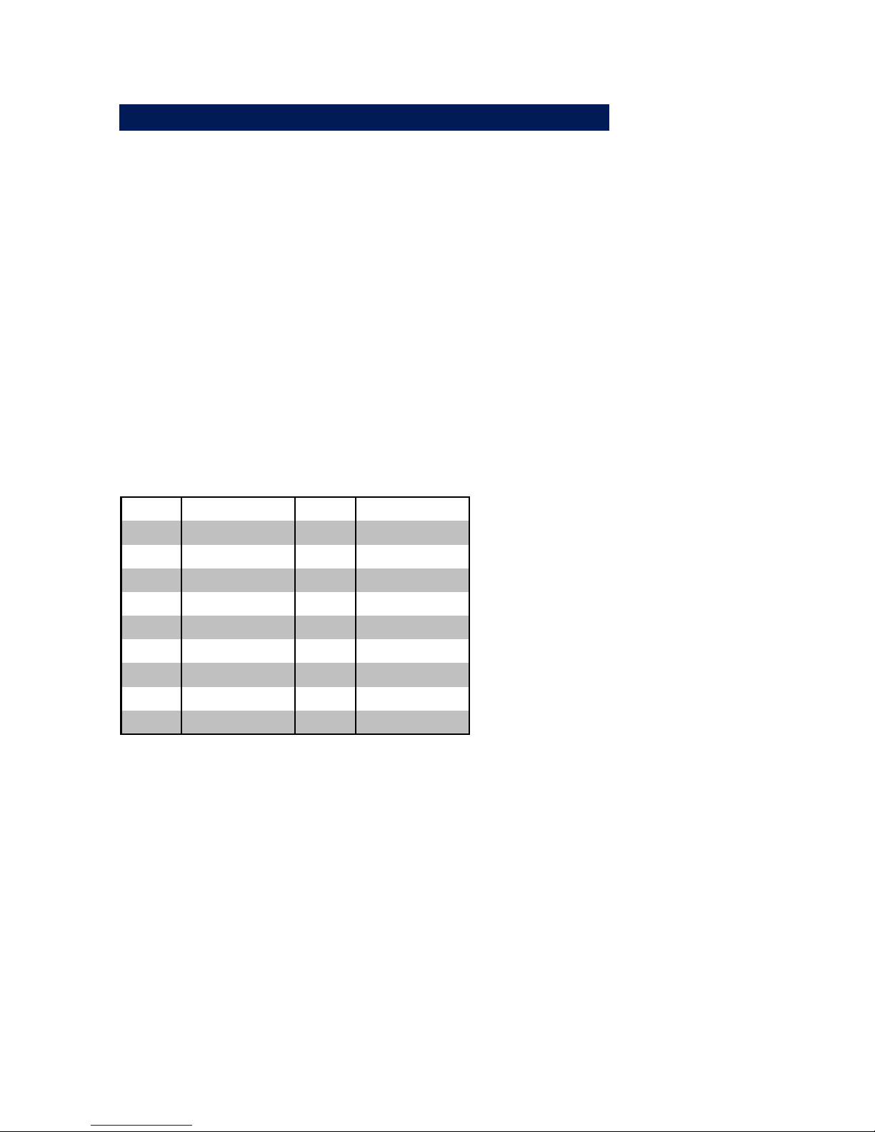
The pinout of the serial port is shown in the following table.
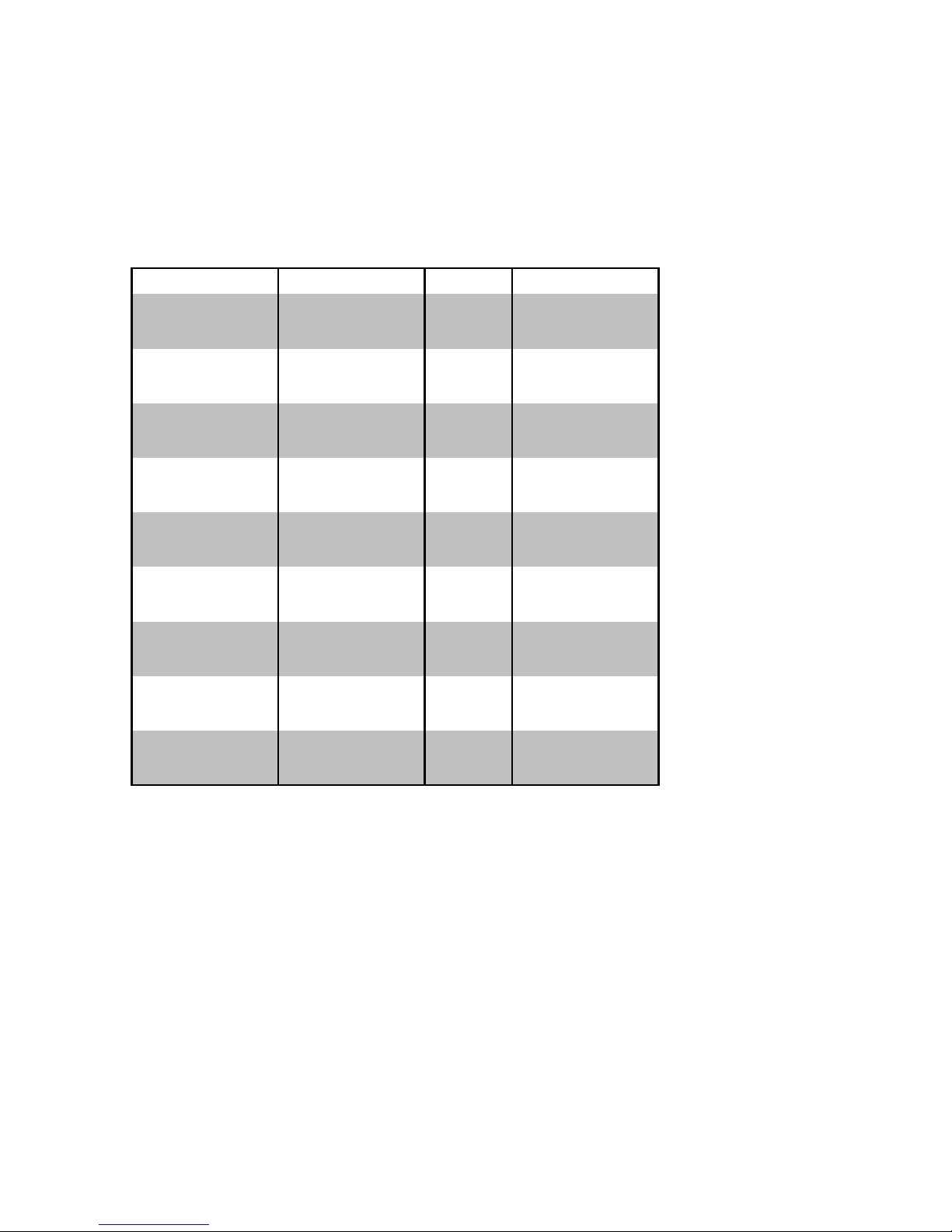
Pin# Function Signal Direction
1 --- DCD Input
2 Data In RxD Input
3 Data Out TxD Output
4 always "on" DTR Output
5 Signal Ground GND ---
6 --- DSR Input
7 Handshake Out RTS Output
8 Handshake In CTS Input
9 --- RI Output
Pinout of the integrated RS232 port
The connection cable between Buffer and peripheral device
must be adapted to the pin configuration of the peripheral
device. Corresponding wiring examples are shown on the next
page.
Page 36
36
W&T
RS232 Battery Buffer, 4 MByte
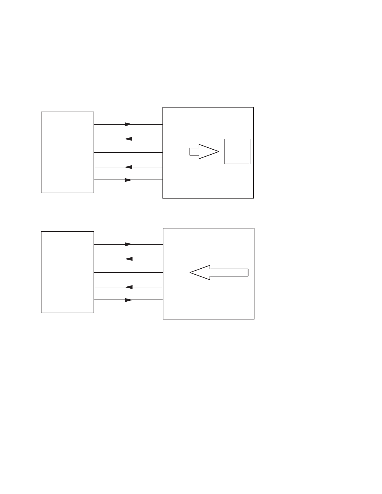
7.2 Connection example
Transport serial data from a PC to a peripheral device with DCE
wiring: Record data from the PC in Rec mode, load the data into
the peripheral using Play.
DB9
PC
2
3
5
8
3
2
5
8
Data In
Data Out
Hands. In
Signal GND
TxD
RxD
GND
CTS
REC
4MByte
Memory
7
Hands. Out
7
RTS
4MByte Memory
Device with
DCE-Pinout
DB25 (DB9)
PLAY
2
3
5
8
3(2)
2(3)
7(5)
4(7)
Data In
Data Out
Hands. In
Signal GND
TxD
RxD
GND
CTS
7
Hands. Out
5(8)
RTS
RS232 Battery Buffer
RS232 Battery Buffer
Connection example for recording and playing data
7.3 Handshake procedure
The serial port on the Buffer can be set for hardware or XON/
XOFF handshake. Operating the Buffer without handshake
should be avoided, since it can result in loss of data.
When the buffer is completely filled with data, an XOFF code is
output on the corresponding interface. and when the next
character is received the output of the hardware handshake
protocol is set to block.
Page 37

37
W&T
RS232 Battery Buffer, 4 MByte
If the Buffer receives an XOFF code or detects a block level on
the hardware handshake input, it stops sending of data no later
than one byte after detecting this state. If the Buffer receives an
XOIN code or detects an enable level on the hardware handshake input, it immediately resumes data transmission.
The XON and XOFF codes are used only for flow control. They
are not data, and may not be included in the user data. If on
the other hand hardware handshake is used and the Buffer is
correspondingly configured, the XON and XOFF codes are
treated like normal data.
When the hardware handshake input is open or incorrectly
wired, the Buffer may not send any data. If you use software
handshake and configure the Buffer accordingly, this problem
will not occur
.
Page 38
38
W&T
RS232 Battery Buffer, 4 MByte
7.4 Setting the DIL switches
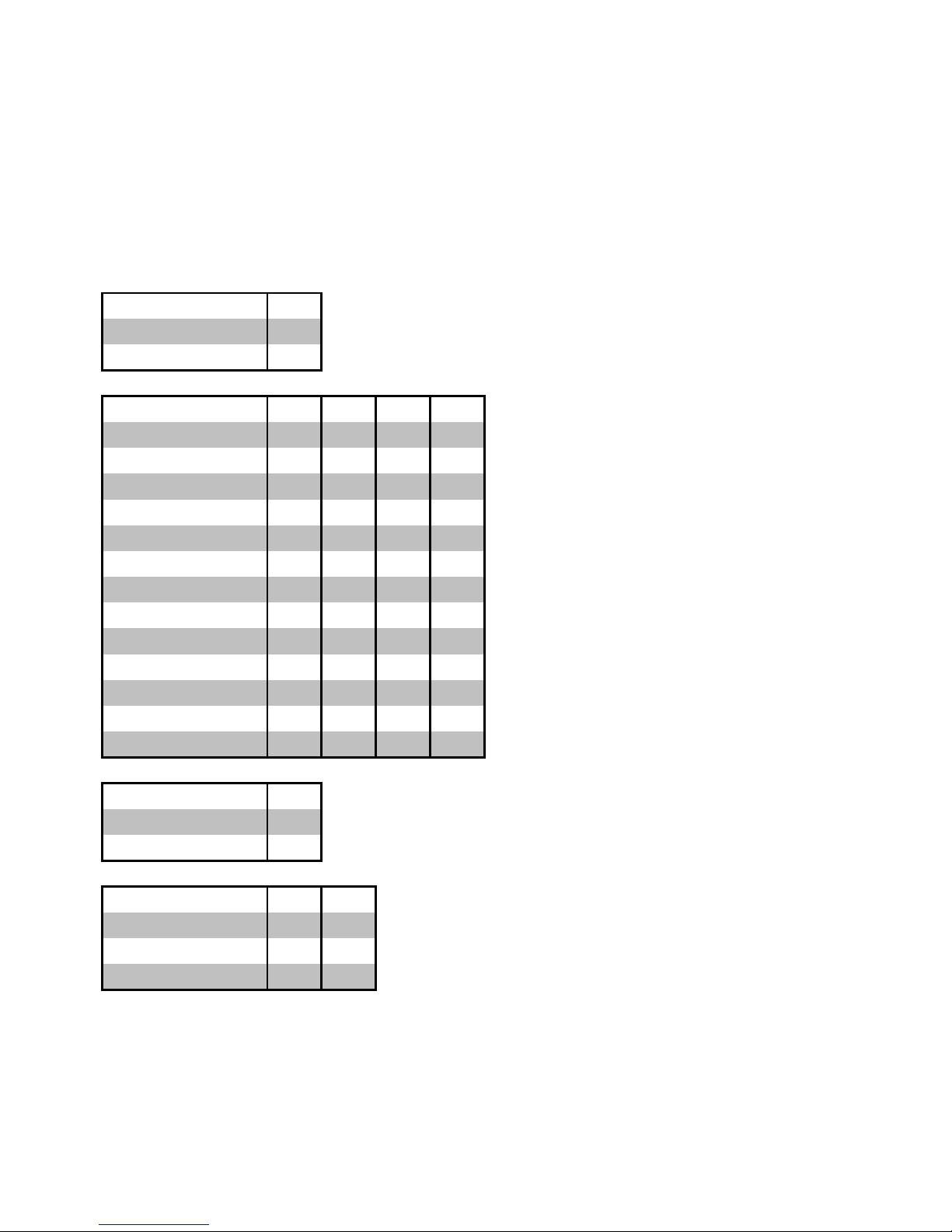
The individual switches on the externally accessible switch
bank determine the baud rate, the number of data bits, the
parity and the handshake procedure. The function of the individual switches is explained in the following table.
Handshake S1
Hardware-Handshake off
Software-Handshake ON
Baudrate S2 S3 S4 S5
150 Baud off off off off
300 Baud ON off off off
600 Baud off ON off off
1200 Baud ON ON off off
2400 Baud off off ON off
4800 Baud ON off ON off
9600 Baud off ON ON off
19200 Baud ON ON ON off
38400 Baud off off off ON
57600 Baud ON off off ON
64000 Baud off ON off ON
76800 Baud ON ON off ON
115200 Baud off off ON ON
Databits S6
7 Datenbits off
8 Datenbits ON
Parity S7 S8
No ON off
Odd off ON
Even ON ON
Switch settings for serial formats
Page 39

39
W&T
RS232 Battery Buffer, 4 MByte
8 Startup
Starting up an RS232 interface often proves difficult, since both
the pin assignments and the transmission parameters must
agree to enable error-free data transmission. To check the
configuraiton, the RS232 Batter Buffer has a setting dump
function which can be very useful at installation.
8.1 Settings dump
The integrated settings dump in the Buffer can be used as a
first test as part of startup, whereby the Buffer independently
generates a text which shows all the programmed settings.
The settings dump has various functions:
. Testing the connection of the data and ground line
. Testing the transmission parameters
. Clear overview output of all settingts
. Handshake test for data output from the device
To be able to generate the settings dump even if the handshake conditions are incorrect, the dump is output when the
interface is blocked, but at a very low baud rate. Specifically:
. Handshake enabled: Fast output of the dump
. Handshake blocked: Slow output of the dump
Page 40

40
W&T
RS232 Battery Buffer, 4 MByte
8.2 Output settings dump
To generate the settings dump, hold down the Play key and
turn the device on by connecting to an AC adapter or pressing
the On key in battery mode. The settings dump is shown in the
following illustration of device settings:
PU 40,6000;;SI 0.2,0.3;DT
LB
LB RS232 PORTABLE BUFFER, 4 MBYTE WITH BATTERY
LB VERSION 1.0
LB
LB BAUD 9600
LB DATA 8
LB PARITY NO
LB
LB HANDSHAKE HARD
LB
Page 41

41
W&T
RS232 Battery Buffer, 4 MByte
9 Technical Data
Serial connection: 1x RS232 (9-pin SUB-D male with
DTE configuration)
ESD rating: up to 15kV per IEC 801-2, Level 4
Baud rate: 150..115.200 baud
Data format: 7, 8 data bits, No, Even, Odd Parity
Handshake: Selectable hardware- or
XON-/XOFF handshake
Supported signals: RxD, TxD, Handshake In, Hand-
shake Out
Buffer size: 4 MByte Flash-Speicher
Supply voltage: Included AC adapter or type AA
battery
Battery life: Rechargeable battery included:
typ. 10h @ 22°C
Ambient operating temp.: Storage: -40..+65°C
Operating: 0..+60°C
(depending on battery used)
Housing/dimensions: Aluminum housing,
115 x 90 x 34mm
Weight: approx. 500g incl. power supply
Scope of delivery: - RS232 Battery Buffer, 4 MByte
- AC adapter for office applications
- Rechargeable battery (Type AA)
for stand-alone operation
Page 42

42
W&T
RS232 Battery Buffer, 4 MByte
 Loading...