

Page 1

13
Subject to error and alteration
W&T Universal Fiber Optic Interface Converter
Manual
Universal FO Interface Converter
Model 81215
Release 1.0
W&T
Page 2

14
W&T Universal Fiber Optic Interface Converter
© 10/2012 by Wiesemann & Theis GmbH
Subject to error and alteration:
Since it is possible that we make mistakes, you mustn’t use
any of our statements without verification. Please, inform us
of any error or misunderstanding you come about, so we can
identify and eliminate it as soon as possible.
Carry out your work on or with W&T products only to the
extent that they are described here and after you have completely read and understood the manual or guide. We are not
liable for unauthorized repairs or tampering. When in doubt,
check first with us or with your dealer.
Page 3

15
Subject to error and alteration
W&T Universal Fiber Optic Interface Converter
Glass fiber optic transmission lines are the solution of choice
when you need to implement absolutely noise-free serial
data transmission over long distances and/or in noisy
environments.
Whereas the attenuation with plastic fiber optics places a limit
of maximum 100 meters on the attainable cable length, the
distances achievable with glass fiber optics are significantly
greater and at a comparable cable cost.
The fiber-optic solution offers another significant advantage: The data transfer is carried out with minimal delay and
enables the processing of real-time protocols.
Wiesemann & Theis offers an entire family of various fiber
optic interfaces that allow you to convert critical I/O ports
or serial ports into an optical port for connecting glass fiber
optic cable.
This interface family is described on the following pages
along with the corresponding technical data and including
connection examples.
For up-to-date information on new developments, see our
Internet site at http://www.wut.de or check the e-mail
short notices at the W&T Interface Club, which you can also
subscribe to from the W&T Homepage.
Page 4

16
W&T Universal Fiber Optic Interface Converter
Index
Universal FO Interface RS232/RS422/RS485, #81215 ......... 17
Function.....................................................................................................17
Power Supply ..........................................................................................17
Galvanic isolation and ESD protection.........................................17
Display elements ................................................................................... 18
Serial Port .................................................................................................19
RS232 mode ............................................................................................. 19
RS422 mode ............................................................................................. 19
RS485 mode ............................................................................................. 19
RS422, RS485 4-wire bus master application .......................... 19
RS485 4 wire / RS485 2-wire application with echo .............. 20
RS485 2 wire application without echo .....................................20
Termination .............................................................................................20
Optical Interface .................................................................................... 21
Housing .....................................................................................................22
Technical Data ........................................................................................ 23
Page 5

17
Subject to error and alteration
W&T Universal Fiber Optic Interface Converter
Universal FO Interface RS232/RS422/RS485, #81215
Function
The W&T fiber optic interface converter 81215 allows
bi-directional conversion of an RS232, RS422 or RS485
interface into a fiber optic interface with a transmission speed
of up to 500.000 bps.
The interface works independently of the data format used
and converts one data line in each direction.
Well-known SC connectors are used for connecting the glass
fiber optic cable, whereas the serial interface is configured as
a 9-pin SUB-D connector.
Power Supply
The supply voltage for the Interfaces is provided through an
integrated switching regulator. This regulator has a variable
input voltage range and allows the Interface to be powered by
any DC voltage between 12 and 48 volts.
The supply voltage is polarity reversal protected and can be
connected on the underside of the Interface through the included plug-in screw terminal.
Galvanic isolation and ESD protection
The serial port of the fiber optic converter is galvanically
isolated from the supply voltage through a DC/DC converter
with an isolation voltage of 1kV. All signal lines for the serial
interface are protected by ESD-immune interface chips against
static discharge for voltages up to 15 kV corresponding to IEC
801-2, Level 4.
Page 6
18
W&T Universal Fiber Optic Interface Converter
Connectors
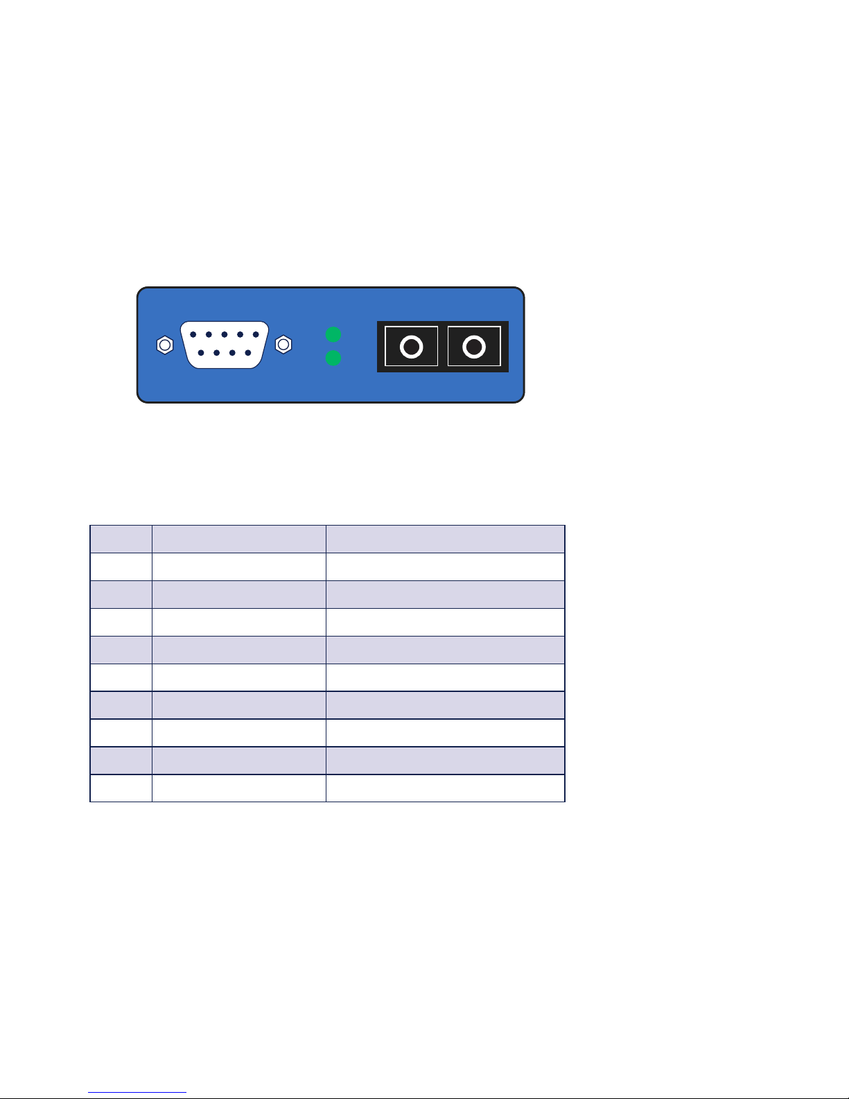
The fiber optic cables are connected to the converter using SC
series connectors, with a DB9 plug for the serial connection.
The arrangement of the signal connectors on the front panel
of the interface can be seen from the following illustration:
The serial connection of the fiber optic converter is configured as a DB9 plug. The pin configuration can be seen in the
following table:
Pin#
RS232 signal RS422 / RS485 signal
1 n.c. TxD A (-)
2 RxD RxD A (-)
3 TxD DTR A (-) (active level)
4 DTR (active level) n.c.
5 Signal GND Signal GND
6 n.c. TxD B (+)
7 RTS (active level) RxD B (+)
8 n.c. DTR B (+) (active level)
9 n.c. n.c.
Display elements
The Interfaces feature two LED’s, with the Power LED
indicating correct supply voltage and the Data LED data
communication in both directions.
Serial Port
Power LED
Data LED TxD RxD
Fiber Optic SC
Page 7

19
Subject to error and alteration
W&T Universal Fiber Optic Interface Converter
Serial Port
The combined RS232/RS422/485 interface of the fiber optic
converter can be set to various operating modes using the
DIL switches located near the serial port. These modes are
described below:
RS232 mode
This mode provides one data channel each (RxD and TxD) in
both directions.
RS422 mode
This mode provides one data channel each (RxD and TxD)
in both directions.The RS422 sender and receiver chips are
always active.
RS485 mode
In all RS485 modes there is always one data channel available
in each direction. The operating modes differ only in how the
RS485 driver and receiver chips are controlled.
RS422, RS485 4-wire bus master application
One data channel and one handshake channel in each direction are available. The RS422/RS485 receivers and transmitters
are always active in this operating mode.
Page 8

20
W&T Universal Fiber Optic Interface Converter
RS485 4 wire / RS485 2-wire application with echo
One data channel in each direction is available. The RS485
output driver is activated automatically with each transmission of data, and goes to the high impedance state again
after the end of transmission. The RS485 receiving channel is
always active in this operating mode.
RS485 2 wire application without echo
One data channel in each direction is available. The RS485
output driver is activated automatically with each transmission of data, and goes to the high impedance state again
after the end of transmission. The RS485 receiving channel is
deactivated when the driver is on, but is switched on when
the driver is in the high impedance state.
Please see the following table for an explanation of the
operating mode DIP switch:
Operating mode
SW1 SW2 SW3 SW4 SW5 SW8
RS232 OFF OFF OFF OFF OFF ON
RS422, RS485, 4-wire bus-master OFF OFF OFF ON OFF OFF
RS485, 4-wire/2-wire with echo OFF ON OFF ON OFF OFF
RS485, 2-wire without echo ON ON OFF ON OFF OFF
Termination
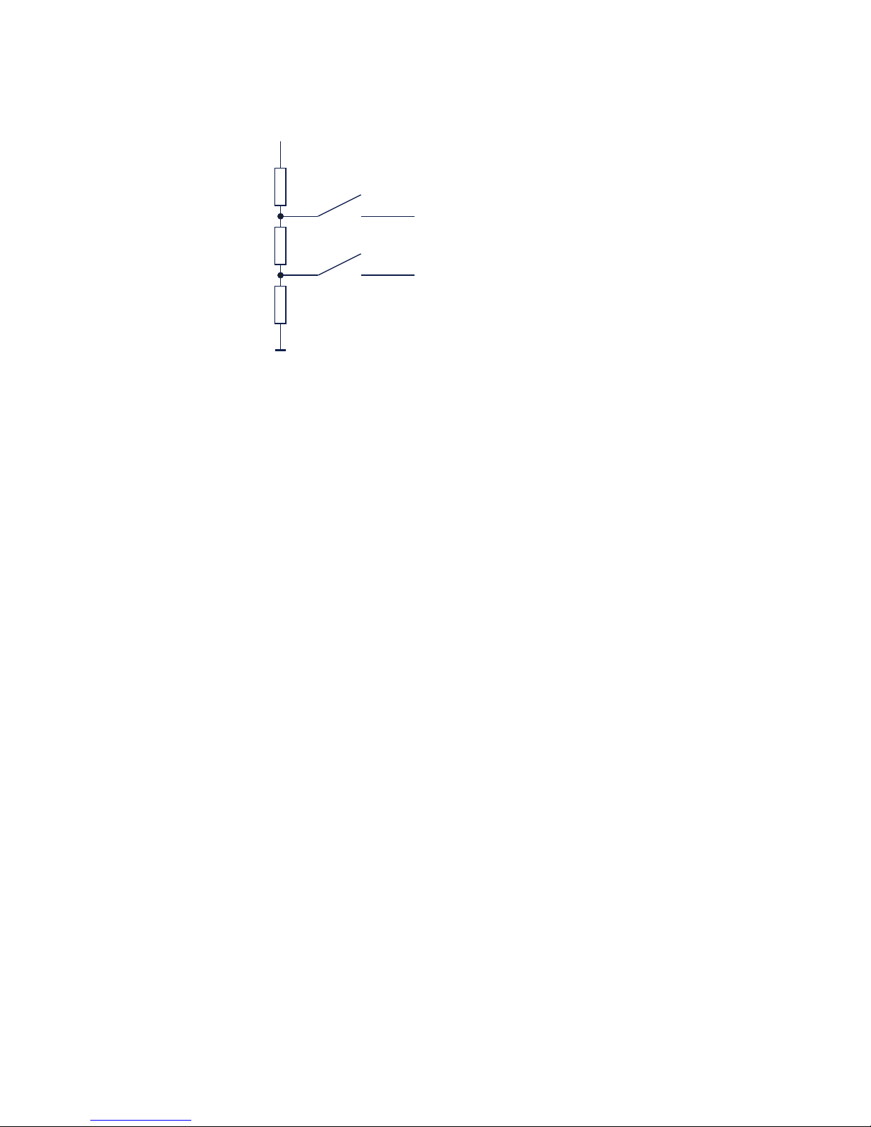
For all RS485 operating modes it is essential that the bus
system be terminated with a termination network which
assures a defined rest state in the high-impedance phases
of bus operation. The bus system can be connected to a
termination network by closing switches #6 and #7 on the
interface module:
Page 9
21
Subject to error and alteration
W&T Universal Fiber Optic Interface Converter
Optical Interface
The W&T Interface 81215 uses common single-mode duplex
9/125µm glass fiber optic cable or 50/125µm and 62.5/125
µm multimode duplex glass fiber optic cable, which due to its
wide use in network technology is easily and inexpensively
available
The light used for data transmission has a wavelength of
1310 nm.
Depending on the attenuation value of the glass fiber optic
cable used, data transmission over a distance of up to 20
km is possible using the Interface in its standard version.
A special version with a more powerful transmitter enables
transmission over up to 40 km and is available on request.
When using the Interface on single-mode cables there are
no limitations with respect to the minimum required cable
length. In this mode the reserve between maximum output
power of the transmitter and clipping limit of the receiver 5dB
in the worst case.
120O
+5V
SW6
SW7
Data In B
Data In A
330O330O
Page 10

22
W&T Universal Fiber Optic Interface Converter
If the Interface is used however on multimode cables, the high
coupled power of the transmitter can result in clipping with
short cable lengths.
In this case we recommend use of a 5dB attenuator on the
Interface output, which can be ordered from W&T as article
number 81900.
Housing
The W&T Fiber Optic Interface is contained in a plastic
housing for mounting on standard rails according to DIN
EN 50022-35.
To configure the RS232/RS422/RS485 Interface, the enclosure must be opened to set the mode type/termination DIL
switches on the interface module.
For this purpose we recommend threading a SUB-D connector
with connector body onto the Interface and use the threaded-on connector to assist in removing the housing cover
from the housing body.
Page 11

23
Subject to error and alteration
W&T Universal Fiber Optic Interface Converter
Technical Data (I)
Serial Interface:
Operating modes: RS232, RS422
RS485 4-wire & 2-wire applications
Baud rate: RS232: 0..230 KBaud
RS422/485: 0..500 KBaud
Data format: any
Transmitted signals: RxD, TxD
Serial connector: 9-pin SUB-D plug
Optical Interface
FO cable connector: SC plug adapter
ST plug adapter on request
Fiber optic medium: Duplex single mode fiber 9/125 µm
Duplex multi mode fiber
50/125µm or 62,5/125µm
Wavelength: 1310 nm
Output power: Single mode fiber:
min. -12dBm, max. -8dBm
(Class 1 Laser Product)
Receiver sensitivity: max. -22dBm
Maximum input power: max. -3dBm
Optical budget: min. 10dB
Maximum distance: Single mode fiber: min. 20km
@0,35dB/km (40km on request)
Multi mode fiber: min. 5km
@1dB/km
Minimum line
attenuation: Single mode fiber: 0dB
Multi mode fiber: 3dB
(with less attenuation, the use of an
additional attenuator may be
required, e.g. W & T # 81900)
Page 12

24
W&T Universal Fiber Optic Interface Converter
Technical Data (II)
Power supply:
Supply voltage: 12..48 V DC
Operating current: typ. 30mA at 12V DC
Power connector: Plug-in screw terminal, 5.08mm
spacing, labeled „L+“ and „M“
Galvanically isolation: min. 1 kV between serial interface
and power supply
Misc:
Ambient temperature: Storage: -40..+70°C
Operation: 0..+70°C
Permissible relative
humidity: 0..95% rH (non condensing)
Housing: Small plastic housing
for top hat rail mounting
Dimensions: 105 * 75 * 22 mm
Weight: approx. 100 g
Packing list: 1x Fiber optic interface converter
1x screw terminal
 Loading...