

Page 1

W&T
www.WuT.de
Manual
Installation, Startup and Application
POF Interface Converters
and Tools
valid for:
#81009: RS232 <> POF, 9 pin Standard
#81029: RS232 <> POF, 9 pin Low Power
#81025: RS232 <> POF, 25 pin DCE
#81026: RS232 <> POF, 25 pin DTE
#81600: POF Cutting Tool
Release 05/2019
Page 2

W&T Plastic Fiber Optic Interfaces and Tools
© 05/2019 by Wiesemann & Theis GmbH
Subject to errors and changes:
Since we can make mistakes, none of our statements should be
used without checking. Please let us know of any mistakes or
misunderstandings you are aware of, so that we can recognize and
eliminate them quickly.
Perform work on and with W&T products only as described here and
only if you have read and understood the manual fully. Unauthorized
use can result in hazards. We are not liable for the consequences
of unauthorized use. When in doubt, check with us or consult you
dealer!
2
Page 3

W&T Plastic Fiber Optic Interfaces and Tools
Wiesemann & Theis offers an entire family of compact self-powered
ber optic interfaces that allows you to convert RS232 serial ports
into an optical port for connecting POF cable.
This interface family is described on the following pages along
with the corresponding technical data and including connection
examples.
For up-to-date information on new developments, see our Internet
site at http://www.wut.de or check the e-mail short notices at the
W&T Interface Club, which you can also subscribe to from the W&T
Homepage.
Subject to error and alteration
3
Page 4

W&T Plastic Fiber Optic Interfaces and Tools
Index
Legal Notices ...............................................................................5
Warning note concept .......................................................................... 5
Qualied personnel .............................................................................. 6
Disposal ................................................................................................ 6
Symbols on the product and on the part label ................................... 6
Safety instructions .......................................................................7
General precautions ............................................................................. 7
Intended use ......................................................................................... 7
Electrical safety .................................................................................... 8
Optical radiation ................................................................................... 8
EMC ....................................................................................................... 8
Notes for use of the ber optic interfaces ..................................... 9
Ambient conditions for the use of POF cables ................................ 10
Interface RS232 <> Plastic Fiber Optic ........................................ 11
Function .............................................................................................. 11
Power supply ...................................................................................... 11
Pinout and connectors ...................................................................... 12
Assembly ............................................................................................ 13
Common technical data: ................................................................... 14
Cutting tool for plastic ber optics, Model 81600 ....................... 15
Background information .................................................................... 15
Preparing the cutter ........................................................................... 16
Cutting ber optic cable .................................................................... 16
Stripping ber optic cables................................................................ 18
Replacing the cutter ........................................................................... 18
Technical Data .................................................................................... 19
4
Page 5

W&T Plastic Fiber Optic Interfaces and Tools
Legal Notices
Warning note concept
This manual contains notes which must be observed for your
personal safety and to prevent equipment damage. The notes are
called out with a warning triangle. Depending on the hazard level
the warning notes are represented in decreasing order of hazard as
follows:
DANGER
1
Indicates a hazard which will result in death or serious injury if no
appropriate safety measures are taken.
WARNING
1
Indicates a hazard which can result in death or serious injury if no
appropriate safety measures are taken.
CAUTION
1
Indicates a hazard which can result in slight injury if no appropriate
safety measures are taken.
NOTE
1
Indicates a hazard which can result in equipment damage if no
appropriate safety measures are taken.
When multiple hazard levels are present the warning note for the
highest level is used. If the warning triangle for personal injury is
used, then a warning for equipment damage may also be added in
the same warning note.
Subject to error and alteration
5
Page 6
W&T Plastic Fiber Optic Interfaces and Tools
Qualied personnel
The product described in this manual may be installed and placed
in operation only by personnel who are qualied for the respective
task.
In addition the documentation for the respective task must be
followed, especially the safety and warning notes included in it.
Qualied personnel have received training and experience which
enable them to recognize risks associated with handling the
described products and to avoid possible hazards.
Disposal
Electronic devices may not be disposed of with household waste,
but rather be brought to a proper electronics waste disposal facility.
A complete Declaration of Conformity for the described devices can
be found on the respective datasheet pages on the W&T Homepage
at http://www.wut.de.
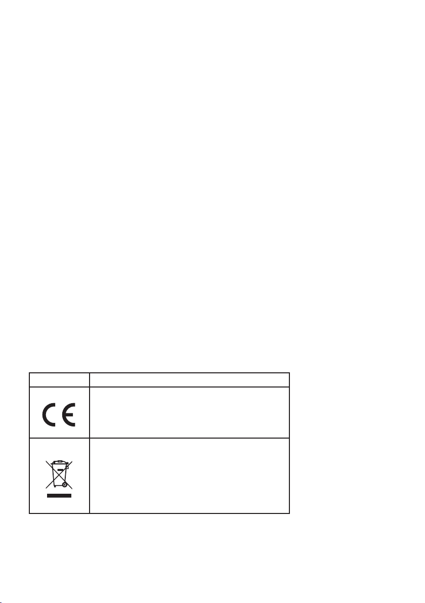
Symbols on the product and on the part label
Symbol Explanation
CE marking
The produce meets the requirements of the
corresponding EU Directives.
WEEE marking
The product may not be disposed of with
household waste, but rather in accordance with
the disposal regulations for electrical waste that
prevail where the device is installed.
6
Page 7

W&T Plastic Fiber Optic Interfaces and Tools
Safety instructions
General precautions
This manual is intended for the installer of the described devices
and must be read and understood before beginning any work. The
devices are to be installed and placed in service only by an electrical
specialist.
Intended use
DANGER
1
The ber optic interfaces from Wiesemann & Theis convert the data
signals from RS232 interfaces into light signals, thereby enabling
the transmission of serial data over plastic ber optic cables. This
allows the interfaces to suppress compensation currents which
can ow as a result of potential differences between the connected
devices when directly copper connections are used. Such currents
can cause interference with data transmission or even destroy the
interfaces.
The interfaces described in this manual are primarily designed
for protecting RS232 ports and for ensuring noise-free data
transmission in noisy environments.When using the interfaces
for personal protection against contact with hazardous voltages,
observe the relevant safety standards and regulations.
Any other use or modication of the interface convertors is not
permitted.
Subject to error and alteration
7
Page 8

W&T Plastic Fiber Optic Interfaces and Tools
Electrical safety
WARNING
1
If an additional power supply is used, it must provide safe isolation
of the low-voltage side from the supply network in accordance with
EN60950-1 / EN62368-1. In addition, the power supply must have an
LPS feature.
Optical radiation
NOTE
1
All W&T ber optic interfaces for plastic ber optic cables use a
standard LED with a wavelength of 660nm as the optical emitter.
Because of the limited energy which the serial port has available, the
LEDs only couple an optical power of typ. -7dBm (approx. 0.2mW)
into the bers.
This precludes any health risk from the optical radiation.
EMC
NOTE
1
Only shielded serial signal cables should be used to connect ber
optic interfaces. Alternately the interfaces can of course be plugged
directly into the respective RS232 port.
The ber optic interfaces then meet the industrial noise limits and
the stricter emissions limits for residential and small businesses.
8
Page 9

W&T Plastic Fiber Optic Interfaces and Tools
Notes for use of the ber optic interfaces
All specifications for maximum transmission parameters refer
to operation of the interfaces on serial ports equipped with type
MC1488 RS232 drivers and at a voltage of ±12V. The specications
also presume that the handshake lines of the interface are enabled.
If the interfaces are supplied only from the data lines, and when
operating on low-eciency RS232 ports you must take into account
limitations with respect to maximum transmission length, baud rate
and temperature range.
Since maintaining of all three parameters is a direct function of the
construction of the RS232 port and a solid power supply for the
ports, and these parameters have a mutual effect, it is not possible
to suggest specic values.
Practice has shown that for RS232 ports equipped with MAX232compatible IC’s, no operating restrictions exist as long as the
handshake lines on the port are enabled.
Laptop ports with low output levels are however only in exceptional
cases able to provide the ber optic interfaces with sucient power.
For short distances, however (up to max. 20 meters), there is a
special power-saving version 81029, which can be purchased for
such applications.
When there are power supply problems, it is always however
possible to supply the interface converter externally through its
handshake inputs with a voltage of up to 9V, or to use ber optic
interfaces with their own power supply (such as our model 81201).
The specied minimum distance of 5 meters for the 81009 Interface
only applies if the Interface is operated on an RS232 port with high
output levels. If under these condi tions a short cable length is
required, a model 81029 may also be used.
Subject to error and alteration
9
Page 10

W&T Plastic Fiber Optic Interfaces and Tools
Ambient conditions for the use of POF cables
If the POF cable is permanently exposed to a high relative humidity,
the cable attenuation will increase signicantly. Although this effect
is reversible with decreasing humidity values, it can lead to transmission failures if a combination of large cable length, fast baud
rate and limited performance of the serial interface is used.
For reliable optical data transmission even in humid environments,
the length of the POF cable should not exceed 50 meters for the
81009 model and 70 meters for the 81025/81026 models.
For larger lengths, glass bre should be used to ensure long-term
reliable operation under the mentioned operating conditions.
10
Page 11

W&T Plastic Fiber Optic Interfaces and Tools
Interface RS232 <> Plastic Fiber Optic
The W&T Plastic Fiber Optic Interfaces, type 81009, 81025, 81026
and 81029 permit bi-directional transmission of RS232 signals by
the means of duplex plastic ber optic cable.
Function
The Interfaces support one data line in each direction and transmit
data over a distance of max. 100 meters (dependent on the model
of the interface convertor).
The transmission medium is standard duplex plastic fiber optic
cable, which is inexpensive and extremely easy to work with and
install. The use of ber optic as a trans mission medium ensures
perfect galvanic isolation between the connected devices and clean
transmission even in noise-prone environments.
The interfaces convert both of the data lines, while the optional
handshake lines can be used to carry additional supply voltage for
the interface. The converter uses jumper resistors between RTS and
CTS as well as DTR and DSR for enabling the connected interface,
so that as a rule no additional jumpers are required in the connector.
Power supply
The W&T Fiber Optic Interfaces sources its supply voltage from the
connected RS232 lines, and does not require any additional external
power supply. Getting sucient power to the Interfaces requires that
the data lines as well as the handshake lines be connected.
Subject to error and alteration
11
Page 12

W&T Plastic Fiber Optic Interfaces and Tools
Pinout and connectors
The fiber optic connection for the interface is configured as a
self-locking coupling for duplex plastic ber optic, with the RS232
interface formatted as DB9/DB25 connector. Refer to the following
table for connector pin assignments:
Pinout RS232 <> POF interface, model 81009 and 81029
pin# RS232 signal
2 data out
3 data in
4 connection to pin 6
5 signal GND
6 connection to pin 4
7 connection to pin 8
8 connection to pin 7
Pinout RS232 <> POF interface, model 81025
pin# RS232 signal
2 data in
3 data out
4 connection to pin 5
5 connection to pin 4
6 connection to pin 20
7 signal GND
20 connection to pin 6
Pinout RS232 <> POF interface, model 81026
pin# RS232 signal
2 data out
3 data in
4 connection to pin 5
5 connection to pin 4
6 connection to pin 20
7 signal GND
20 connection to pin 6
12
Page 13
W&T Plastic Fiber Optic Interfaces and Tools
Assembly
Connecting the plastic fiber optic cable to the W&T Fiber Optic
Interfaces requires no special tools:
• Trim the ber optic cable to the desired length using a sharp
knife and separate the individual duplex conductors back from
the cut point to a distance of around 2 cm.
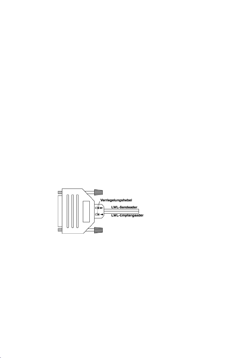
• Pull the locking levers on the ber optic female connector back
towards the module along the upper side of the coupling. At the
same time insert the separated end of the ber optic duplex line
into the ber optic coupling female.
• Releasing the locking levers locks the fiber optic into the
coupling.
• To release, pull the two locking levers on the top of the coupling
towards the module, and pull the ber optic cable out of the
female.
The arrows on the top side of the coupling show the location of the
emitter and receiver lines.
Please note that when connecting two ber optic components, the
emitter of the rst must always be connected to the receiver channel
of the second component.
A visible red light beam is always sent along with data, so that the
sending line can always be easily identied.
Subject to error and alteration
13
Page 14

W&T Plastic Fiber Optic Interfaces and Tools
Common technical data:
Baud rate: 110..115,200 baud
Data format: any format
Signal lines: RxD, TxD (full duplex)
Power supply: through the RS232 signals
POF cable adapter: integrated socket with automatic
interlocking of the ber-optic cable
Transmitter type: LED
Optical output power: typ. -7dBm
Wavelength: approx. 660 nm
Ambient temperature: Storage: -40..+70°C
Operation: 0..+50°C
Housing: SUB-D adapter housing
Weight: approx. 30 g
RS232 <> POF interface, 9-pin, #81009
Transfer distance: typically 5 to 80 m
RS232 adapter: 9-pin SUB-D socket for PC
Delivery: RS232 <> POF interface, #81009
RS232 <> POF interface, 9-pin, #81029
Transfer distance: typically 0 to 20 m
RS232 adapter: 9-pin SUB-D socket for PC
Delivery: RS232 <> POF interface, #81029
RS232 <> POF interface, 25-pin, DCE, #81025
Transfer distance: typically 0 to 100 m
RS232 adapter: 25-pin SUB-D socket, DCE pinout
Delivery: RS232 <> POF interface, #81025
Gender changer, 25-pin, m/m
RS232 <> POF interface, 25-pin, DTE, #81026
Transfer distance: typically 0 to 100 m
RS232 adapter: 25-pin SUB-D plug, DTE pinout
Delivery: RS232 <> POF interface, #81026
Gender changer, 25-pin, f/f
14
Page 15

W&T Plastic Fiber Optic Interfaces and Tools
Cutting tool for plastic ber optics, Model 81600
The 81600 cutting tool enables fast and precise trimming of duplex
POF cables size 4.4 x 2.2 mm without the necessity of grinding or
polishing the resulting cut surfaces.
Background information
For short runs it is generally sucient to trim the plastic ber optic
cable using simple tools such as a sharp knife. In these cases the
additional attenuation caused by a less than ideal cut is non-critical
for the stability of the data transmission. The light intensity at
the receiving location is almost always sufficient for a reliable
connection regardless of cut-related losses.
But when you begin to approach the maximum permissible distance,
the cut quality is important in terms of the achievable distance
and the stability of the connection, and can determine whether a
connection is feasible or not. A perfect cut can give you up to an
additional 20 meters of distance in borderline conditions.
The decisive criterion for the quality of the cut is a at cut at right
angles to the cable axis, so that as little light as possible is lost
through scatter or reflection. Such cuts can be achieved using
the described cutting tool without requiring additional grinding or
polishing of the cut surface.
Important: This tool is not suitable for trimming glass ber cables.
Any attempt to use the tool for cutting glass fiber media will
permanently damage the cutting element.
Subject to error and alteration
1
15
Page 16
W&T Plastic Fiber Optic Interfaces and Tools
Preparing the cutter
The plier is shipped from the factory with a safety lock which must
be removed before using the tool.
Cutting ber optic cable
Open the plier by pressing the two grips on the tool together and
then releasing them.
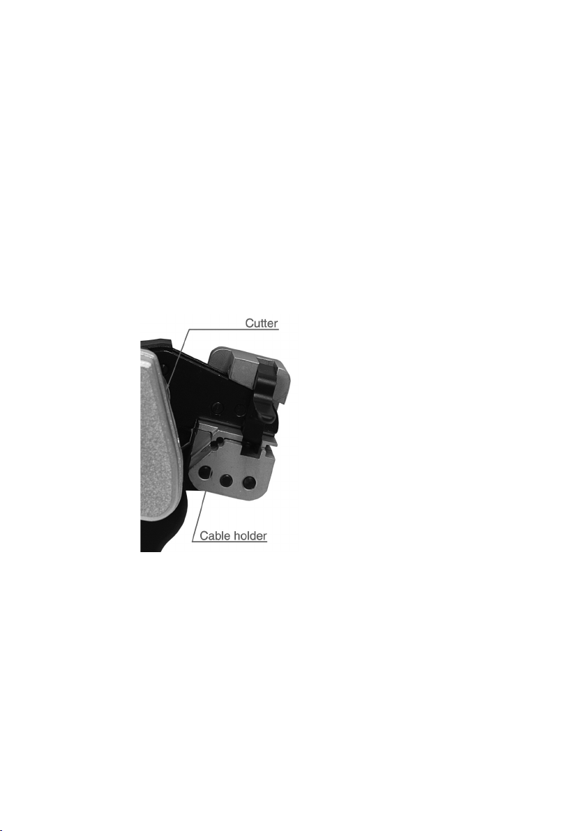
Place the duplex ber optic cable into the holder provided in the
clamping block of the plier:
Close the plier by pressing the two grips together until the ber optic
cable is securely held in the clamping block. While doing this take
care not to squeeze the grips until they touch, since this will release
the plier again.
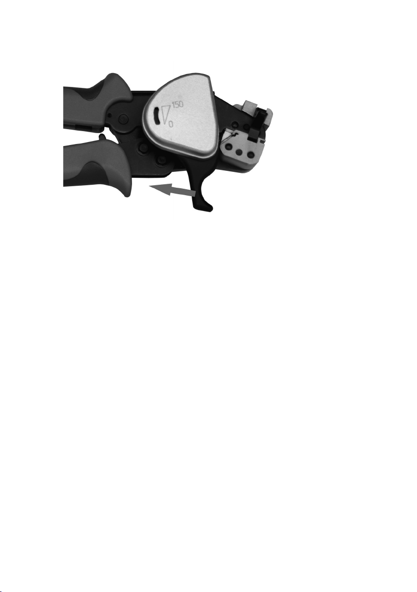
Then press the cutting wheel against the fiber optic cable by
squeezing the trigger-like grip towards you using your index nger.
16
Page 17
W&T Plastic Fiber Optic Interfaces and Tools
A rm pull with the index nger quickly and cleanly cuts the ber
optic cable. To remove the cable from the clamping block, open the
plier.
With each cutting operation the cutting wheel rotates forward by
a slight angle, thus signicantly increasing the service life of the
tool.
Subject to error and alteration
17
Page 18
W&T Plastic Fiber Optic Interfaces and Tools
Stripping ber optic cables
In addition to the cutting function, the plier is also capable of
stripping duplex ber optic cable. This function is now required
however when using ber optic cable together with W&T ber optic
interfaces.
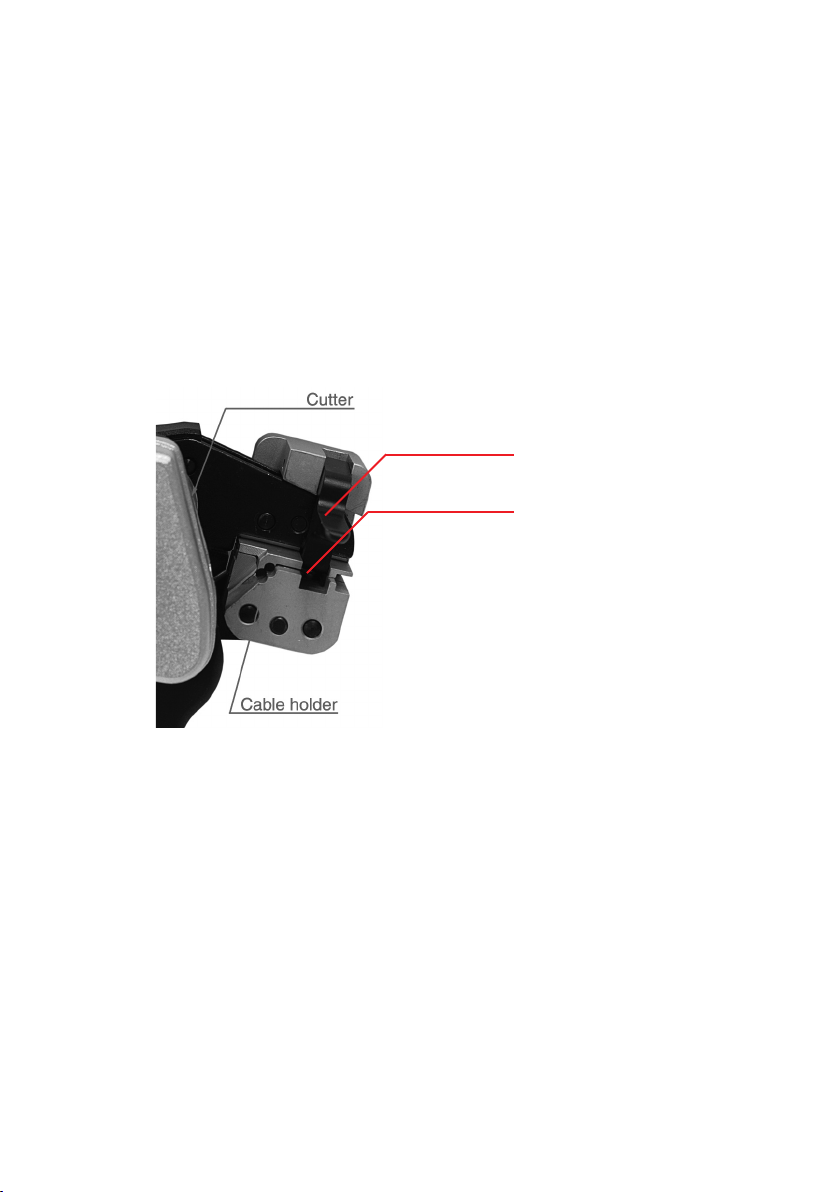
To strip the cable, insert it into the stripping holder of the clamping
block and pull the associated lever up to expose the inner cable
section.
Stripping lever
Stripping holder
Replacing the cutter
In order to ensure consistent cutting quality, the cutter monitors
the number of cuts made and indicates the end of the useful life
of the cutting wheel in a small window on the side. When the life
expectance is reached, which occurs after 1260 cutting operations,
the entire safety cutter needs to be replaced.
The safety cutter including cutting wheel is user replaceable as a
self-contained unit and can be ordered from W&T under Article No.
81602.
18
1
Page 19

W&T Plastic Fiber Optic Interfaces and Tools
Technical Data
Functions: Cutting and stripping
ber optic cables
Compatible media: 2.2 mm Simplex- and 4.4 x 2.2 mm
Duplex bers with 980um ber core
Dimensions: 200 mm x 80 mm x 50 mm
Weight: 520 g
Included: Fiber optic cutting tool
Allen key for releasing
transport safety lock
Subject to error and alteration
19
Page 20

W&T Plastic Fiber Optic Interfaces and Tools
Wiesemann & Theis GmbH
Porschestr. 12
42279 Wuppertal / Germany
Mail [email protected]
Web www.WuT.de
Tel. +49 (0) 202/2680-110
Fax +49 (0) 202/2680-265
20
 Loading...