

Page 1

Release 2.0, January 2010
Model 58620
Firmware 2.10 or higher
Manual
LAN-Modem
W&T
Page 2

W&T
© 01/2010 by Wiesemann und Theis GmbH
Subject to error and alteration:
Since it is posssible that we make mistakes, you mustn’t use
any of our statements without verification. Please, inform us of
any error or misunderstanding you come about, so we can
identify and eliminate it as soon as possible.
Carry out your work on or with W&T products only to the extent
that they are described here and after you have completely read
and understood the manual or guide. We are not liable for
unauthorized repairs or tampering. When in doubt, check first
with us or with your dealer.
Page 3
W&T
Introduction
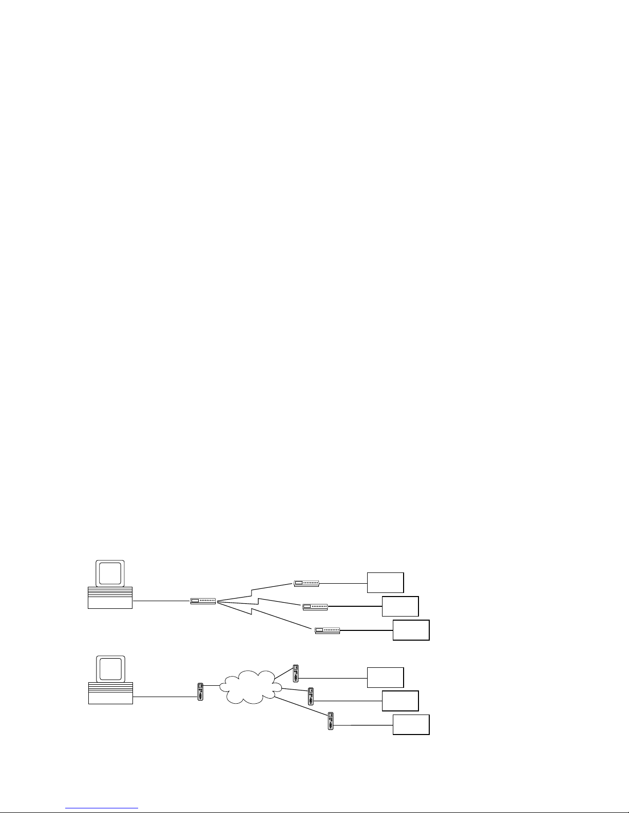
The LAN-Modem permits devices that require dial-up modems
for communicating to use the Intranet or Internet instead of the
telephone system. On a serial interface, the LAN-Modem
behaves in a way this is compatible with standard modems for
the telephone system; the only difference is that the dial-up
number is replaced by an IP address.
Modem
Intranet /
Internet
“ATDT <Tel. No.>”
RS232
RS232
RS232
RS232
before:
LAN Modem
LAN Modem
RS232
“RING”
now:
serial
device
serial
device
serial
device
RS232
Modem
Modem
Modem
RS232
“RING”
serial
device
serial
device
serial
device
“ATDT <IP. No.>”
RS232
Page 4

4
W&T
Inhalt
1 Quickstart 7
1.1 Installation in flow chart form 8
1.2 Factory Default setting 9
2 Assigning the IP address 11
2.1 Configuring network parameters with WuTility 12
2.2 Serial assigning of IP, subnet mask and gateway 15
2.3 Assigning the IP using DHCP protocol 17
2.3.1 Activating/Deactivating DHCP 17
2.4 Assigning the IP using BOOTP protocol 20
3 Interfaces and displays 23
3.1 Ethernet connection 24
3.2 RS232 interface 26
3.3 Supply voltage 27
3.4 LED displays 28
4 LAN-Modem operation settings 29
4.1 Standard mode LAN-Modem <> LAN-Modem 30
4.2 Mode LAN-Modem <> Virtueller Modemport 31
5 Modem Operation 35
5.1 Serial transmission parameters 36
5.2 Command syntax 37
5.3 Command and data mode 38
5.4 All AT commands 39
5.4.1 A (ATA) 40
5.4.2 D (ATD[IP address]) 41
5.4.3 E (ATE[0|1]) 44
5.4.4 H (ATH) 45
5.4.5 In (ATI[0–8]) 46
5.4.6 O (ATO) 47
5.4.7 Q (ATQ0|1) 48
5.4.8 Sn? (ATS[0-40]?) 49
5.4.9 Sn=x (AT[0–40]=[0–255]) 50
5.4.10 Vn (ATV[0|1]) 52
5.4.11 Zn (ATZ[0|1]) 53
5.4.12 &C (AT&C[0|1]) 54
Page 5

5
W&T
Subject to error and alteration
5.4.13 &D (AT&C[0|1|2|3]) 55
5.4.14 &Fn (AT&F[0|1]) 56
5.4.15 &K (AT&K[0|3|4|5|6]) 57
5.4.16 &Sn (AT&S[0|1]) 58
5.4.17 &Vn (AT&V[0|1|2]) 59
5.4.18 &Wn(AT&W[0|1]) 60
5.4.19 &Yn (AT&Y[0|1]) 61
5.4.20 &Zn=x (AT&Z[0|1|2|3]=[IP address]) 62
5.4.21 %Bn (AT%B[2-8]) 63
5.4.22 %Dn (AT%D[7|8]) 64
5.4.23 %Pn (AT%P[0|1|2]) 65
5.4.24 %Sn (AT%S[1|2]) 66
5.4.25 %Nn (AT%N[0|1]) 67
5.4.26 ** (AT**) 68
Appendix 69
A1 Extended configuration of the LAN-Modem 70
A1.1 Starting the Telnet session 70
A1.2 Configuration of the TCP server port (Local Port) 71
A1.3 Configuration of the System Name 72
A1.4 Configuration of the System Password 72
A1.5 Configuration of Keep Alive Check 73
A1.6 Configuration of Link Speed 73
A2 Firmware update of the LAN-Modem 75
A3 Reading/Sending Configuration Profiles 82
A4 Software reset of the LAN-Modem 83
A5 The Modem Protocol on the TCP Level 84
A6 Used ports and network security 85
A7 Technical Data 88
Page 6

6
W&T
Page 7

7
W&T
Subject to error and alteration
1 Quickstart
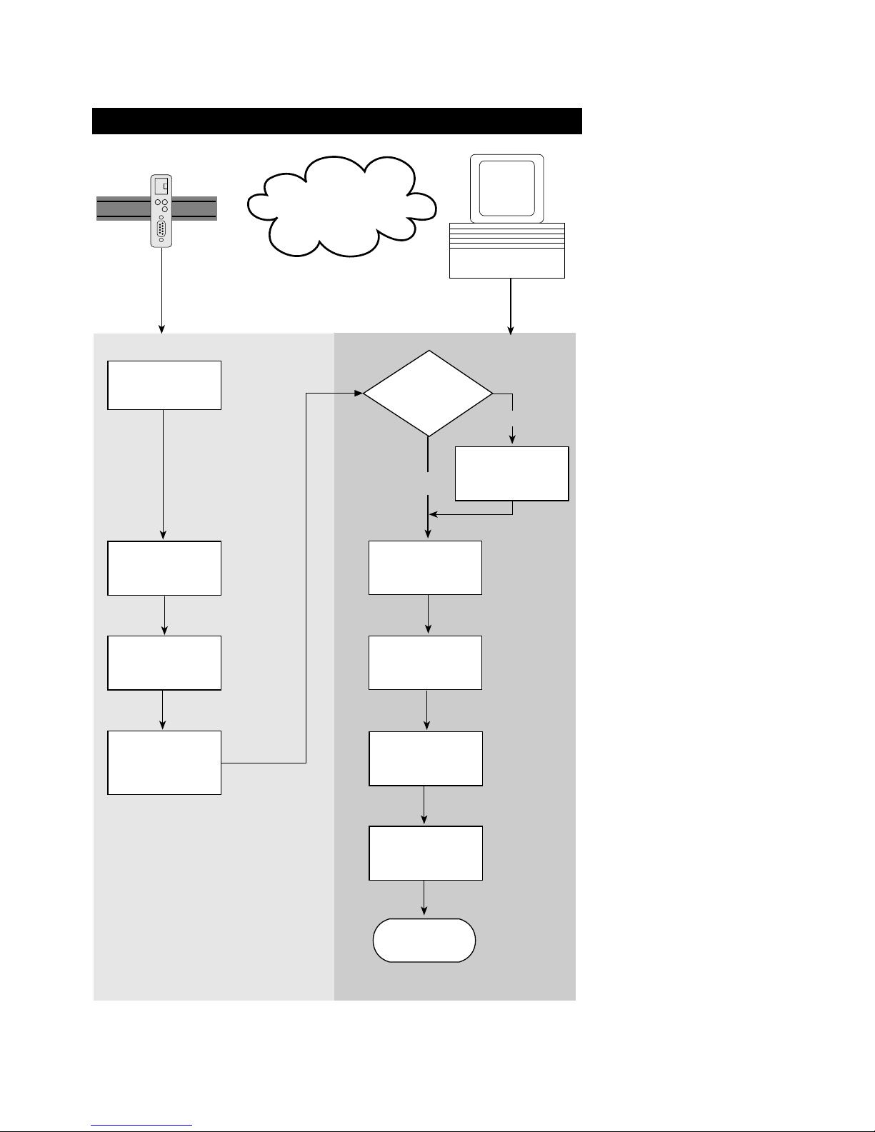
Already experienced users of LAN-Modems will find on the two following
pages a flow chart with the essential steps for start-up as well as the
configuration. Detailed information can be found then in the following
sections.
Page 8
8
W&T Quickstart
1.1 Installation in flow chart form
Select site
Connect
supply voltage
LAN-Modem Windows PC
with TCP/IP
WuTility
installed?
yes
Connect
network cable
Finish
Network
no
Optain IP
address, subnet
mask, gateway
address
Install
WuTility with
product CD
Button:
IP address
Enter IP address,
subnet mask,
gateway
Start
WuTility
Select
LAN-Modem in
inventory list
Page 9

9
W&T Quickstart
1.2 Factory Default setting
The list contains an overview of the most important settings.
Detailed information on the respective parameters can be found
in later sections of this manual.
Network settings
Hardware connection: Auto negotiating
IP address: 0.0.0.0
Gateway address: 0.0.0.0
Subnet mask: 255.0.0.0
DHCP: Active
TCP port for incoming calls: 8000
1
To prevent unintended address assignments or changes,
we recommend deactivating the DHCP, BOOTP and RARP
protocols if they are not expressly used in the respective
network environment.
Serial settings
Baud rate: 9600
Data bits: 8
Parity: NO
Stop bits: 1
Handshake: Hardware (RTS/CTS)
Page 10

10
W&T Quickstart
Page 11

11
W&T
Subject to error and alteration
2 Assigning the IP address
The LAN-Modem is factory set to IP address 0.0.0.0. Before you can make
the entry in the LAN-Modem, you need to specify an IP address that is valid
for your network. You system administrator will provide you with this. If
you have only a small network with no routing, use the IP address of your
PC and simply change the last digit. The IP address must be unique within
the network!
. Assigning IP address, subnet mask and gateway address
using WuTility management tool
. Assigning IP address, subnet mask and gateway address
through the serial port
. Assigning IP address, subnet mask and gateway using
DHCP/BOOTP protocol
. Using the ARP command
Page 12

12
W&T Assigning the IP address
2.1 Configuring network parameters with WuTility
The Windows tool WuTility version 3.0 and higher allows not
only inventorying of LAN-Modem, Com-Server and Web-IO
installations, but also convenient assignment of the following
network-side basic parameters:
• IP address
• Subnet mask, gateway address
• Activating/deactivating BOOTP/DHCP
Assigning requires that the PC and LAN-Modem be in the same
subnet. In firmware revisions 1.45/1.14 and higher the function
is independent of the current address settings in the LAN-Modem, i.e. even changes to parameters not matching the network
are easily made. Any system password which has been set must
however in this case be known.
Downloading and installing WuTility
The most current version can always be found at our Web site
under the following address:
http://www.wut.de
From there use the menu tree on the left side to navigate:
Downloads r Serial Com-Servers
After unzipping the ZIP file, begin installation by doubleclicking on the file wutility_xxxus.msi. WuTility is started from
Start r Programs r W&T Software Toolkit r WuTility
Starting the assignment dialog
First be sure that both the LAN-Modem and the computer you
are using are connected to the same network and are in the
Page 13
13
W&T Assigning the IP address
Subject to error and alteration
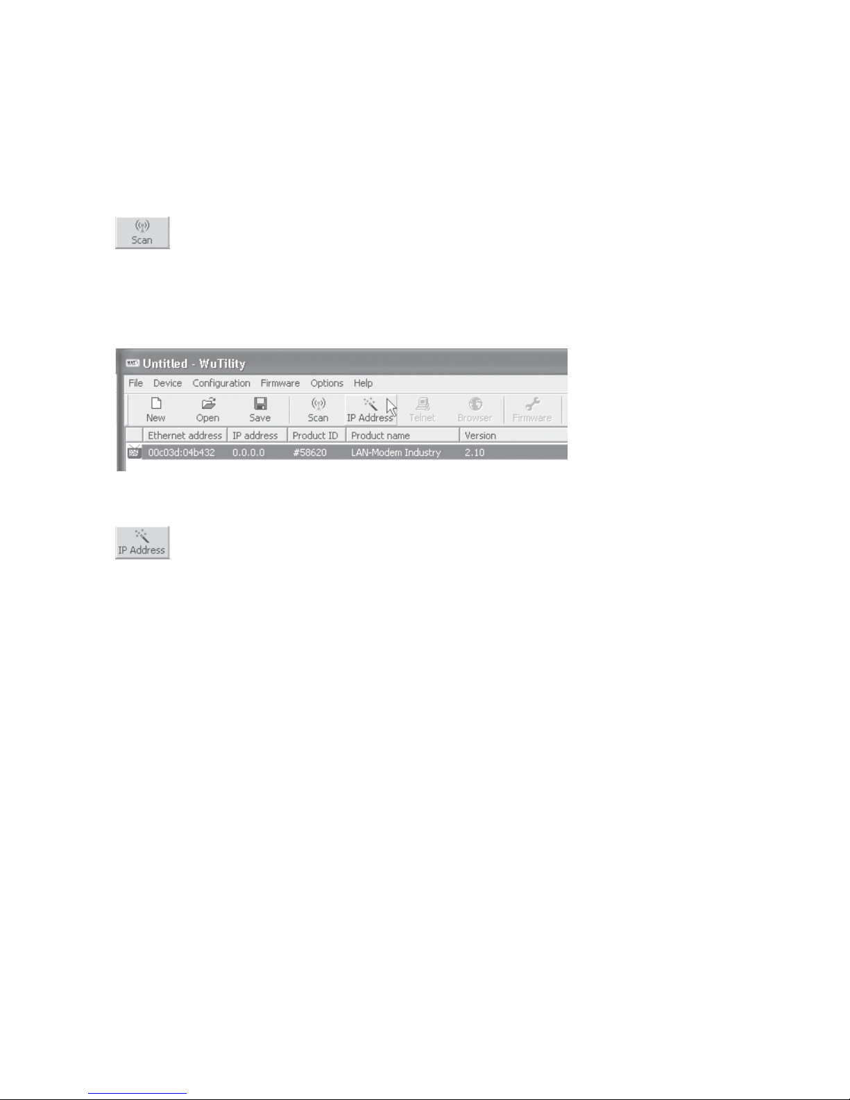
same subnet. When started, WuTility automatically searches the
local network for connected W&T network devices and creates
an inventory list. This search process can be repeated manually
as often as desired by clicking on the Scan button:
Within the inventory list you can identify the desired LAN-Modem based on its MAC address. For initial installations its IP
address is 0.0.0.0.
Select the LAN-Modem and click on the IP address button:
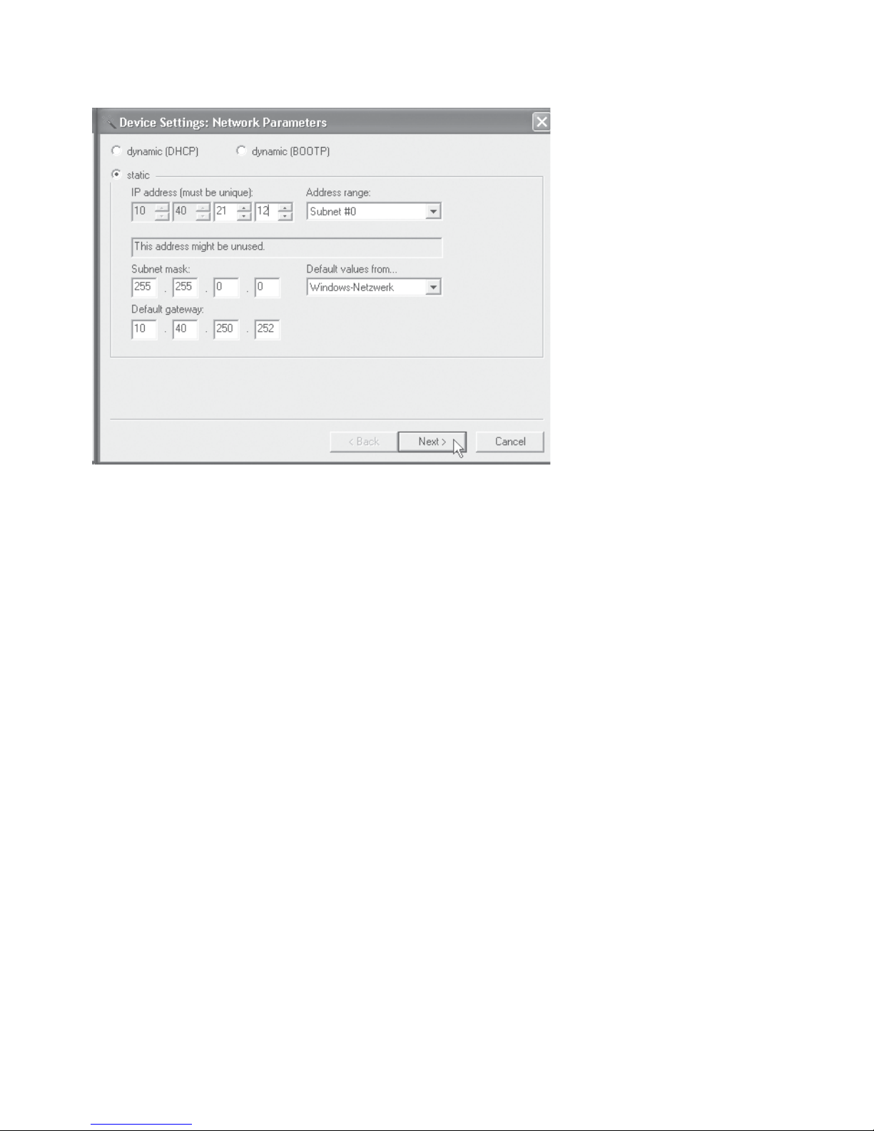
To use the LAN-Modem with dynamic IP parameters, select in
the following dialog box the corresponding option DHCP or
BOOTP and then click on the Next button. Detailed information
about these modes can be found in the section IP Assignment
using DHCP protocol and IP Assignment using BOOTP protocol.
The Static option allows you to assign fixed basic parameters
while simultaneously disabling DHCP and BOOTP protocols in
the LAN-Modem. Enter the desired values for IP address, subnet
mask and gateway address in the corresponding entry fields.
Page 14
14
W&T Assigning the IP address
Clicking on the Next button assigns the network parameters to
the LAN-Modem. After acknowledging the resulting message,
all the columns in the WuTility device list are filled in with
information.
This concludes the network-side startup of the LAN-Modem.
With the exception of a few special settings, the rest of the
configuration is done as for a standard dial-up modem using
the serial port and AT commands.
1
Changing network parameters is protected by the
system password. To prevent improper access, we
recommend assigning a system password for any LAN-Modems
in use. Additional information can be found in the section
Extended configuration of the LAN-Modem.
Page 15

15
W&T Assigning the IP address
Subject to error and alteration
2.2 Serial assigning of IP, subnet mask and gateway
After a LAN-Modem reset a time window of around 2 seconds is
available, during which you can assign a new IP address, subnet
mask and gateway address by entering at least 3 „x“.
1
This serial method functions regardless of whether the
LAN-Modem already has an IP address or not. The
procedure can be repeated as often as desired. Therefore use
this method if you don‘t know the IP address or have forgotten
it.
First connect the serial port of the LAN-Modem to a computer.
For a standard PC or laptop, you will need a 1:1 wired RS232
cable (=modem cable, see section RS232 interface).
The serial transmission parameters of the terminal program you
use should be set to 9600 baud, no parity, 8 bits, 1 stop bit, no
handshake. Reset the LAN-Modem by interrupting the power.
When the green status LED lights up, enter the letter „x“ at least
three times on the terminal, until the LAN-Modem returns the
prompt IPno.+<Enter>.
Use the usual format (xxx.xxx.xxx.xxx) to enter the IP
address, and end the entry by pressing <Enter>. If the entry
was accepted, the acknowledgement is the assigned IP address.
Otherwise you will get a FAIL message followed by the last
current IP address.
2.2.1 Assigning of subnet mask and gateway address
Together with the IP address, the subnet mask and gateway
address can also be assigned serially. The entry is separated
by commas and follows the IP address. Entering as shown in
Page 16

16
W&T Assigning the IP address
the following example will assign IP address 172.17.231.99,
subnet mask 255.255.255.0 and gateway 172.17.231.52 to the
LAN-Modem.
xxx -> LAN-Modem
IP no.+<ENTER>: <- LAN-Modem
172.17.231.99,255.255.255.0,172.17.231.52 -> LAN-Modem
172.17.231.99,255.255.255.0,172.17.231.52-1 <- LAN-Modem
2.2.2 Activating/Deactivating DHCP, BOOTP/RARP
The DHCP and BOOTP/RARP function of the LAN-Modem can
be turned off as part of assigning the IP address serially. To
activate/deactivate the DHCP or BOOTP/RARP client enter one
of the following options directly appended (no space!) to the IP
address and confirm with <Enter>.
• -0
DHCP and BOOTP/RARP = OFF
• -1
DHCP = OFF,
BOOTP/RARP = ON
• -2
DHCP = ON
BOOTP/RARP = OFF
Example: Deactivation of DHCP and BOOTP/RARP
xxx -> LAN-Modem
IP no.+<ENTER>: <- LAN-Modem
172.17.231.99-0 -> LAN-Modem
172.17.231.99 <- LAN-Modem
1
To prevent unintended address assignments or changes,
we recommend deactivating the DHCP and BOOTP/RARP
protocols if they are not expressly used in the respective
network environment. LAN-Modems with incorrectly assigned IP
addresses can be easily found after the fact using the scan
function of the WuTility management tool and reconfigured.
Page 17

17
W&T Assigning the IP address
Subject to error and alteration
2.3 Assigning the IP using DHCP protocol
Many networks use DHCP (Dynamic Host Configuration
Protocol) or its predecessor BOOTP described in the following
section for centralized and dynamic assignment of the network
parameters. DHCP protocol is activated by the factory default
settings, so that in network environments dynamic IP
assignment is sufficient for connecting the LAN-Modem to the
network. The following parameters can be assigned using
DHCP:
• IP address
• Subnet mask
• Gateway address
• Lease time
1
To prevent unintended address assignments or changes,
we recommend deactivating the DHCP and BOOTP/RARP
protocols if they are not expressly used in the respective
network environment. LAN-Modems with incorrectly assigned IP
addresses can be easily found after the fact using the scan
function of the WuTility management tool and reconfigured.
2.3.1 Activating/Deactivating DHCP
The factory default setting is for DHCP protocol active. To
deactivate it or to enable it again later, use one of the following
options.
• Management-Tool WuTility
Select the desired LAN-Modem in the device list and click
on the IP Address button. In the following dialog box enter
the desired option DHCP, BOOTP or Static. Clicking on
Continue then sends the new configuration data to the LANModem.
Page 18

18
W&T Assigning the IP address
• Serial port
As part of serial IP assignment, the following options for
deactivating/activating DHCP and BOOTP can be selected
directly following the address string:
-0 r Deactivates DHCP and BOOTP/RARP
-1 r Activates BOOTP/RARP
-2 r Activates DHCP
A detailed description of the procedure can be found in the
section on Serial assignment of IP, subnet mask and
gateway.
2.3.2 System Name
To support any automatic updating of the DNS system by the
DHCP server, the LAN-Modem identifies itself within the DHCP
protocol with its system name. The factory default setting for
this is LanModem- followed by the last three places of the
Ethernet address. For example the factory set system name of
a LAN-Modem with the Ethernet address 00:c0:3d:01:02:03 is
LanModem_010203. The system name of the LAN-Modem can
be changed in the configuration. For additional information
refer to the section Extended configuration of the Lan-Modem.
2.3.3 Lease-Time
The lease time determined and transmitted by the DHCP server
specifies the Time-To-Live of the assigned IP address. After half
the lease time has expired, the LAN-Modem attempts to extend
the time for the assigned DHCP server and up update the
address. If this is not possible by the time the lease time
expires, for example because the DHCP server can no longer
be reached, the LAN-Modem deletes the IP address and starts a
new cyclical search for alternate DHCP servers for the purpose
of assigning a new IP address.
Because of the absent clock, the lease time associated with the
current IP address is no longer available after a reset. After the
Page 19

19
W&T Assigning the IP address
Subject to error and alteration
restart therefore a corresponding update request is issued with
the original DHCP server. If the latter is not resolvable at this
point in time, the LAN-Modem deletes the IP address and starts
a new cyclical search for alternate DHCP servers.
1
If after the assigned lease time has expired the DHCP
server is not reachable, the LAN-Modem deletes its IP
address. All existing network connections with other network
clients are thereby closed. To prevent such events, we
recommend configuring the assigned lease time in the DHCP
server to infinite if possible.
2.3.4 Reserved IP addresses
A LAN-Modem provides services which other clients in the
network can make use of as needed. To open a connection, they
of course need the current IP address for the LAN-Modem, so
that in such situations it makes sense to reserve a particular IP
address for the LAN-Modem on the DHCP server. This is
generally done by linking the IP address to the unique Ethernet
address of the LAN-Modem, which can be found on the sticker
attached to the housing.
58xxx [Model]
EN=00c03d004a05
OK xxxxxx
Ethernet address
2.3.5 Dynamic IP addresses
Operation with dynamic address assignment, whereby the LAN
modem receives a different IP address after each restart of after
the lease time has expired, is not recommended, since the AT
dial-up command can be used only with numeric IP addresses.
Page 20

20
W&T Assigning the IP address
2.4 Assigning the IP using BOOTP protocol
Many networks use BOOTP as predecessor of DHCP protocol
for centralized and dynamic assignment of IP addresses. The
factory default setting is for BOOTP turned off. You can activate
it e.g. by using WuTility The following parameters can be
assigned:
• IP address
• Subnet mask
• Gateway address
1
To prevent unintended address assignments or changes,
we recommend deactivating the DHCP and BOOTP/RARP
protocols if they are not expressly used in the respective
network environment. LAN-Modem with incorrectly assigned IP
addresses can be easily found after the fact using the scan
function of the WuTility management tool and reconfigured.
2.4.1 Address reservation
BOOTP protocol is based on fixed reservations of fixed IP
addresses for particular Ethernet addresses. This means a LANModem connected to the network only gets an IP address if the
latter was previously stored in the BOOTP server. Check with
your system administrator for creating this reservation. The
Ethernet address of the LAN-Modem can be found on the
housing sticker.
58xxx [Model]
EN=00c03d004a05
OK xxxxxx
Ethernet address
Page 21

21
W&T Assigning the IP address
Subject to error and alteration
Once the administrator has made the necessary entries, the
LAN-Modem obtains the desired IP address automatically after
each reset. To ensure accessibility of the LAN-Modem even
should the BOOTP server go down, the previous IP address is
retained should there be no reply.
Page 22

22
W&T Assigning the IP address
Page 23

23
W&T
Subject to error and alteration
3 Interfaces and displays
. Ethernet interface
. Serial interface
. Supply voltage
. LED displays
Page 24
24
W&T Interfaces and Displays
3.1 Ethernet connection
The LAN-Modem incorporates an IEEE 802.3-compatible
network interface.
Link-Status
The current link status of all models is indicated by the Error
LED on the device front panel. Flashing at a rate of approx. 1
second indicates that there is no connection to the hub or that
the connection is faulted.
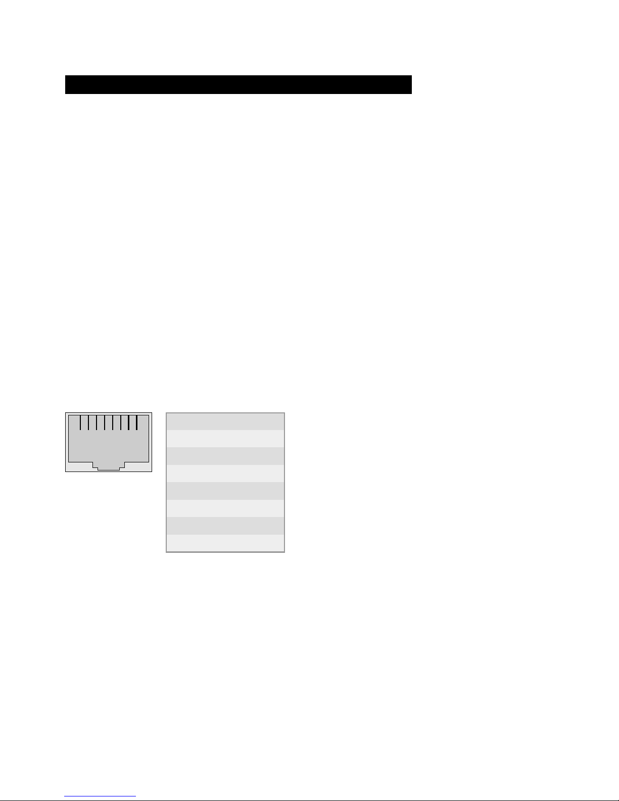
3.1.1 10/100BaseT on RJ45
The LAN-Modem has a 10/100BaseT network interface on a
shielded RJ45 connector. The pin assignments shown below
correspond to an MDI interface, so that the connection to the
hub or switch is made using a max. 100m long 1:1 shielded
patch cable.
1 2 3 4 5 6 7 8
Direction
Out
Out
In
In
In
In
In
In
Signal
Tx+
Tx-
Rx+
nc
nc
Rx-
nc
nv
Pin
1
2
3
4
5
6
7
8
The network connection is galvanically isolated with respect to
the supply voltage as well as the serial interface(s) for at least
500V
rms
.
Auto Negotiation: 10/100BaseT, Full/Half Duplex
LAN-Modems are factory set to operate in Auto-Negotiation
mode on the network side. The data transmission speed and
duplex are automatically negotiated with the connected switch/
hub and set accordingly.
Page 25

25
W&T Interfaces and Displays
Subject to error and alteration
In addition to the Auto-Negotiation mode, both the LAN-Modems as well as many switches can be configured for fixed
transmission parameters with respect to speed and duplex. To
prevent communications problems (duplex mismatch), only the
following two combinations are permissible:
• Both parties (switch and LAN-Modem) are operated in Auto-
Negotiation mode.
• Both parties (switch and LAN-Modem) are configured for the
same (fixed) transmission speeds and duplex mode.
Information on toggling between Auto Negotiation and fixed
transmission speeds can be found in the section Expanded
LAN Modem Settings.
1
Managable switches often have special protocols
(spanning tree, port trunking, ...) as required for
example for uplinks to other switches or broad-band connection
of servers. These protocols are not generally required for
connecting a normal terminal device such as the LAN-Modem,
and they do under some circumstances significantly delay
opening of communication after a new start. We recommend
deactivating these protocols and functions on the port used for
the LAN-Modem. Please consult here with the responsible
network administrator.
Page 26

26
W&T Interfaces and Displays
3.2 RS232 interface
The pin assignments for the RS232 port are identical with that
of a dialup modem, which means that standard cable can be
used. Make sure that the ports for the LAN-Modem and the
serial terminal device are configured for identical transmission
parameters and handshake procedures.
The following table shows the factory configured functions for
the individual signals. These can be modified using the
respective AT commands.
Factory setting
Active for existing connection
Data output
Data input
If deactive, break connection and do not
accept new connection until active again
---
Always active
Hardware handshake input
Data output only when active
Hardware handshake output
active = ready to receive data
deactive = not ready to receive data
For incoming connection alternately 1s
active, 4s deactive until connection is
established; then deactive
Direction
Output
Output
Input
Input
GND
Output
Input
Output
Output
Pin
1
2
3
4
5
6
7
8
9
AT command
AT&Cn
---
---
AT&Dn
AT&Sn
AT&Kn
AT&Kn
---
Page 27

27
W&T Interfaces and Displays
Subject to error and alteration
3.3 Supply voltage
The supply voltage for the LAN-Modem can be brought in on
the adjacent screw terminals on the underside of the housing.
DC voltage of any polarity or AC voltage may be used. The
reverse polarity protection results in the following various
maximum and minimum values for the supply voltage:
• AC: 9Vrms (- 10%) - 30Vrms (+10%)
• DC: 12V (-10%) - 48V (+10%)
The current draw is indicated in the technical appendix.
Page 28

28
W&T Assigning the IP address
3.4 LED displays
Status and error information is indicated by the LAN-Modem
using three LEDs having various blink codes.
• Power-LED
Indicates the presence of supply voltage. If the LED is not
full on, please check your power supply connections.
• Status-LED
Flashes when there is network activity with the LAN-Modem.
Periodic flashing indicates that the port has a connection
to another station.
• Error-LED
The error LED uses various blink codes to indicate error
states on the device or serial port:
1 x flashing = Check network connection
The LAN-Modem is not receiving a link pulse from a hub.
Check the cable and hub.
2 x flashing/3 x flashing
There is an internal communication problem. Connections to other LAN-Modems are no longer possible or are
defective. The problem may be correctable by resetting
to the factory default settings.
All LEDs on = Self-test error
The self-test performed after each start or reset of the
LAN-Modem could not be correctly finished due for
example to an incomplete update of the firmware. In this
state the LAN-Modem is no longer operational. Please
return the unit for repair.
Page 29

29
W&T
Subject to error and alteration
4 LAN-Modem operation settings
In addition to the traditional paired operation of the W&T LAN-Modem it is
also possible to communicate on a Windows computer using virtual
modem ports.
■ Standard mode
■ Download and installation of the W&T COM redirector
■ Communication with virtual modem ports
Page 30

30
W&T LAN-Modem operation settings
4.1 Standard mode LAN-Modem <> LAN-Modem
Like standard modems in a land line network, the devices are
connected in pairs, i.e. there is a LAN-Modem on both the
calling and receiving side.
Starting with an AT dial-up command (ATD...) the calling LANModem opens a TCP connection to the destination system. In
response to this incoming call, the character sequence RING
and the hardware signaling are generated on the serial side on
the RI line. After the call is answered with the ATA command
there exists then a character-transparent data connection.
Page 31
31
W&T LAN-Modem operation settings
Subject to error and alteration
4.2 Mode LAN-Modem <> Virtueller Modemport
If one side of the connection is a Windows application, then on
this side it is possible to use a virtual modem port of the W&T
COM Port Redirector. This emulates a local COM port including
a connected LAN-Modem. In other words, just as with a
hardware LAN-Modem the AT command set described in the
following section can be used for control and monitoring the
connection.
1
The following sections contain only a brief guide to the
function of the W&T COM Port Redirector and modem
ports. Additional information on all configuration options for the
W&T COM Port Redirector can be found in the online help.
Download of the W&T COM redirector
The latest version of the COM Port Redirector can always be
downloaded from our Web site.
http://www.wut.de
The simplest way to navigate from there is by using the menu
tree on the left side of the page. Follow the
Downloads r Com-Servers
path to get to the website containing a direct link to the COM
Port Redirector.
Use of the COM Port Redirector in connection with W&T LANModems is free and not subject to any licensing requirements.
Page 32

32
W&T LAN-Modem operation settings
Installation/deinstallation of the COM port redirector
System requirements for installing the W&T Com Port
Redirector:
• Operating system Windows NT, 2000, XP, Vista, Windows7
• Login as administrator or with administrator rights
1
Installation of the W&T Com Port Redirector is done as an
update to any already existing older versions. All settings
and connection parameters are saved and remain available
unchanged. To prevent restarting of the computer when your
are finished, quit all applications and services which are
actively accessing COM ports before performing the update.
After downloading and unpacking the archive, start the MSI file
to start installation. In addition to setting up the core driver, a
link to the configuration tool in the Windows Start menu under
W&T COM Port Redirector is created.
The W&T COM Port Redirector is uninstalled using Windows
software administration. Start the Software applet in the control
panel and there select the entry W&T COM Port Redirector.
Clicking on the Remove button removes the COM Port
Redirector from the system.
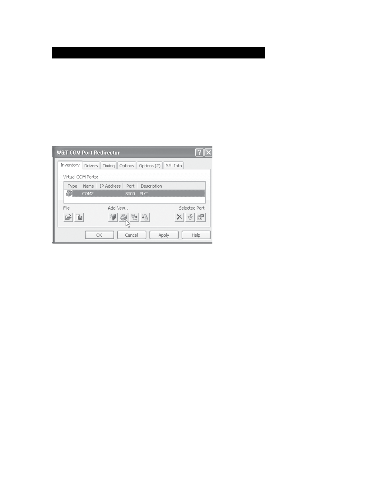
Setting up virtual modem ports
To set up a new virtual modem port, start the COM Port
Redirector configuration tool from the Windows Start menu and
click there on the LAN-Modem button. The resulting dialog
window provides only the two following configuration options:
If this option is enabled, the virtual modem port on the
specified TCP port also allows incoming calls, comparable to a
hardware LAN-Modem, whereby the TCP port number used is
functionally the same as the local port setting in the LAN-Modem. Additional information can be found in the section
Expanded Configuration of the LAN-Modem.
Page 33

33
W&T LAN-Modem operation settings
Subject to error and alteration
The optional name entered here is used only for identifying the
port within the inventory list of the W&T COM Port Redirector. It
has no effect on the actual operation or communication.
Page 34

34
W&T LAN-Modem operation settings
Page 35

35
W&T
Subject to error and alteration
5 Modem Operation
After the network configuration is complete, the LAN-Modem behaves on
the serial side just like a dial-up modem with an AT command set, except
that the TCP/IP LAN takes the place of the telephone line. As far as the
controlling application or controlling device is concerned, all that needs to
happen is that the previously used telephone number is replaced by the IP
address of the distant terminal.
■ Serial transmission parameters
■ Command syntax
■ List and explanation of all AT commands
Page 36

36
W&T Modem Operation
5.1 Serial transmission parameters
Unlike modems for the telephone network, the LAN-Modem is
not able to automatically detect the baud rate of the terminal.
The following transmission format is factory set:
Baud: 9600
Data bits: 8
Parity: none
Stop bits: 1
Flow control: RTS/CTS
The AT commands AT%Bn, AT%Dn, AT%Pn and AT%Sn can be
used to select the following alternate transmission speeds and
character formats:
Baud:
1200, 2400, 4800, 9600, 19200, 38400, 57600
Data bits:
7, 8
Parity:
none, even, odd
Stop bits:
1, 2
For additional information, refer to the detailed description of
the respective AT command.
Page 37

37
W&T Modem Operation
Subject to error and alteration
5.2 Command syntax
The LAN-Modem accepts all the AT described in the following
sections as long as they corresponding to one of the following
patterns and are finished with a CR:
letter [ number]
& letter [ number]
% letter [number]
\ letter [ number]
Non-supported AT commands, such as %V or L2 have no effect
and are simply ignored. Invalid commands on the other hand
generate an error message and in particular end processing of
the current command line. Example: „AT&C0*H0Q1" would run
command &C0 , but not Q1, since the line is no longer
considered starting with the invalid command *H0.
Page 38

38
W&T Modem Operation
5.3 Command and data mode
The LAN-Modem distinguishes on the serial side between two
mode states: command and data mode.
• Command mode
In this mode, which is activated after power-on, the AT
command interpreter operates on the serial interface. The
LAN-Modem is in this state ready to receive and process AT
commands. All data not corresponding to AT syntax is
ignored or acknowledged with an error message. Nothing is
passed on to any communications partner in the network.
The command ATO can be used to switch from command
to data mode during any existing network connection.
• Data mode (Online mode)
This mode is only available while there is a connection to a
communications partner. The AT command interpreter is
now deactivated and all incoming serial data are passed into
the network without any further processing. To switch back
into command mode, use the escape sequence „+++“. To
retain the binary transparency of data mode inspite of the
processing of this character string, the LAN-Modem only
carries out the change if the following times are observed:
minimum 1s no data received
r
Escape sequence r
1s no data received
If this procedure should be unusable in sepcial cases, the S
registers 2 and 12 can be used to modify the Escape
characters as well as the pause time (see command Sn=x).
As an alternative to use of the Escape sequence, the RS232
input DTR can be configured for switching into command
mode. FOr details, see the description of the AT command
&Dn.
Page 39

39
W&T Modem Operation
Subject to error and alteration
5.4 All AT commands
The LAN-Modem accepts all the commands in the table whose
processing is done according to the following rules:
Command
Dx
A
O
H
Zn
En
Qn
Vn
In
Sn?
Sn=x
&Cn
&Sn
&Dn
&Kn
&Fn
&Vn
&Wn
&Yn
&Zn=x
%Bn
%Dn
%Pn
%Sn
%Nn
**n
Description
Dial IP address and go online
Pick up incoming call
Return to an existing connection
Close connection
Close connection and reset modem
local echo on|off
Suppress result codes on|off
Result codes as text instead of number
Firmware information
Read S register
Modify S register
DCD option
DSR option selection
Modem response to DTR option
Flow control between modem and terminal
Restore
Display configuration profiles/connection data
Active profile write
Active profile read
Destination IP address write
Baudrate between modem and terminal
Number of data bits beween modem and terminal
Parity bit between modem und terminal
Number of stop bits between modem and terminal
Allow remote maintenance over network
Start firmware update
Parameter
IP-Adresse
---
---
---
n=0, 1
n=0, 1
n=0, 1
n=0, 1
n=0 - 8
n=0 - 40
n=0 - 255
n=0, 1
n=0, 1
n=0, 1, 2, 3
n=0, 3, 4, 5, 6
n=0, 1
n=0, 1, 2
n=0, 1
n=0, 1
n=0, 1, 2, 3
n=2 - 8 (5)
n=7, 8
n=0, 1, 2
n=1, 2
n=0, 1
n=0, 1
• No other command may follow A, D, O, Z and &Z in the same
command line. In the case of A, O and Z they are ignored,
and in the case of D and &Z they are considered as part of
the dialed number.
Page 40

40
W&T Modem Operation
• Omitting a numerical parameter has the same effect as
indicating a 0.
• The boldface parameters are the standard values that are
created by AT&F.
In addition to these commands, A/ (without a preceding AT or
concluding <cr>) is accepted as an entry to completely repeat
the last command line again.
5.4.1 A (ATA)
Accept incoming call
If the serial application detects an incoming call by means of
the RING sequences send by the LAN-Modem, the call can be
picked up by sending this command. After the network
connection with the communication partner has been
established, the LAN-Modem sends the message CONNECT over
the serial interface and automatically switches to data mode.
Along with each serial output of the RING character string, an
incoming connection request causes the interface signal RI
(=Pin 9) to be set high for approx. 1s.
Page 41

41
W&T Modem Operation
Subject to error and alteration
5.4.2 D (ATD[IP address])
Dial command
The dial command is required for establishing a connection
with another LAN-Modem. Taking the place of the dial-up
number used in telephone networks is the IP address of the
desired LAN-Modem. To maintain compatibility with existing
modem applications, the LAN-Modem accepts here the
following formats:
D [Options] IP address [;]
D [Options] S=n [;]
DL [;]
• Options
Options may consist of any number of letters and special
characters; these characters have no effect on the
connection set-up. By this means it is possible to continue
using an application that employs at this point for example
a T for using tone dialing.
• IP address
The IP address consists of four numbers between 0 and 255
in decimal format. These can be separated by special
characters (e.g. decimal point or comma). Without
separators it is assumed that each number consists of
exactly three digits. If additional digits follow behind the
last number, these are intereted as TCP port numbers. If no
port number is specified, port number 8000 is implied. Valid entries would include for example.:
atd172016232073
atd1720162320738000
atd172.16.232.73
atdt172.16.232.73:8000
Page 42

42
W&T Modem Operation
All three commands have the same effect: An attempt is
made to set up a call to the LAN-Modem having IP address
172.16.232.73 to TCP port 8000.
1
If the preset TCP port number 8000 for the LAN-Mo
dem is not usable in special network environments,
this value can be changed using the Telnet configuration.
Additional information can be found in the section
Expanded Configuration of the LAN-Modem.
• S=0|1|2|3
The LAN-Modem has a non-volatile memory for up to four
destination IP addresses. By specifying a value between 0
and 3, the IP addresses stored here is used for the call setup. If only S is entered without a numerical value, the
addresses stored in position 0 is used. The command &Zn
is used to write to the non-volatile address memory.
• L
When using L instead of the IP address, the dial-up is
repeated using the last used values. If no address has been
dialed since the last reset of the LAN-Modem, the message
ERROR is returned.
• ; (Semicolon)
Entering a semicolon to terminate the dial-up command
causes the LAN-Modem not to automatically return to data
mode after a successful call set-up, but rather to remain in
command mode.
Replies for the dial-up command
• CONNECT
The network connection with the desired destination system
was successfully made, and the serial application connected
therre accepted the call. If the dial-up command was not
terminated with a semicolon, the LAN-Modem is now in data
mode, i.e. all entries are sent transparently to the
communication partner
Page 43

43
W&T Modem Operation
Subject to error and alteration
• NO CARRIER
The network connection to the desired communication
partner was able to be established, but the serial application
there did not pick up the call. The time for which the LANModem waits for the counterpart to pick up the call is stored
in Register S7 and is factory set to 50s.
• BUSY
No network connection to the desired communication
partner could be established. The cause of this may be a
station that is already busy with another connection. In this
case the attempt to establish a connection is rejected.
Another reason may be an unreachable or incorrect IP
address. For very slow network routs to the destination
system, the timeout stored in Register S6 for the TCP
connection set-up can be set to a higher value. The factory
setting is for 3s
Page 44

44
W&T Modem Operation
5.4.3 E (ATE[0|1])
Local echo off|on
This command determines whether the data received on the
RS232 interface in command mode should lbe returned. The
factory setting is for echo on.
ATE0 = Echo off
ATE1 = Echo on
Page 45

45
W&T Modem Operation
Subject to error and alteration
5.4.4 H (ATH)
Quit connection
This command quits the connection. Both serial
communication partners receive the reply NO CARRIER.
!
Page 46

46
W&T Modem Operation
5.4.5 In (ATI[0–8])
Read out firmware information
The I command is used to read out system information
for the LAN-Modem. Of a possible 0-8, only the following
parameters are presently used.
• ATI0
Returns product code 58210 from the LAN-Modem
• ATI3
Returns the firmware version and date of the AT command
interpreter
• ATI4
Returns product name W&T-LANMODEM.
• ATI8
Liefert die Laufzeit des LAN-Modems seit dem Einschalten
bzw. seit dem letzten Reset im Format hh:mm:ss
Page 47

47
W&T Modem Operation
Subject to error and alteration
5.4.6 O (ATO)
Switch to data mode
This command switches (when there is an existing connection)
from command to data mode. If you need for example to
change LAN-Modem parameters during a connection, you must
first use the Escape sequence to switch to command mode. After the desired reconfiguration you can then use the ATO
command to reactivate data mode.
For additional information see Section Command and Data
Mode.
Page 48

48
W&T Modem Operation
5.4.7 Q (ATQ0|1)
Modem replies on|off
Default setting: 0 = ON
Replies generated by the LAN-Modem such as OK or CONNECT
can be turned off by using the Q command:
• ATQ0
The LAN-Modem sends replies
• ATQ1
Reply messages are turned off.
Page 49

49
W&T Modem Operation
Subject to error and alteration
5.4.8 Sn? (ATS[0-40]?)
Read S register
This command is used to read the 41 S registers that determine
the operating behavior of the LAN-Modem. Changing or writing
to the S registers is done using the Sn=x command shown
below.
Page 50

50
W&T Modem Operation
5.4.9 Sn=x (AT[0–40]=[0–255])
Set S register
The LAN-Modem has 41 S registers (S0 to S40) which determine
its operating behavior. The command Sn=x is used to overwrite
the current contents, whereby n specifies the desired register
and x the value to write in decimal format. Only the following
registers presently have meaning for the operation of the LANModem:
Register
S0
S1
S2
S3
S4
S5
S6
S7
S9
S10
S12
S14
S21
S23
S25
S39
Description
Pick up after how many ring characters ? (0=never)
Ring counter
ESC character
Code for CR (Carriage Return)
Code for LF (Linefeed)
Code for BS (Backspace)
Wait time for TCP-connection set-up (seconds)
Waits until other party picks up (seconds)
Time base for carrier generation (1/10 seconds)
Allowed Carrier dropout (1/10 seconds)
Isolation time for ESC sequence (1/50 seconds)
Option bits from commands E, Q, V
Option bits from commands &C, &D, &S
Option bits from commands %B, %N
Allowed DTR-Dropout (1/100 seconds)
Handshake mode (command &K)
Default value
0
43 (=ASCII "+")
13
10
8
3
50
20
50
5
Note the following when writing to the S registers of the LANModem:
• The command Sn=x has only a temporary effect. The
changes can be loaded into the non-volatile memory of the
LAN-Modem by using the &W command. The only
exceptions are registers S3, S4 and S5. These cannot be
permanently stored.
Page 51

51
W&T Modem Operation
Subject to error and alteration
• Registers S14, S21, S23 and S39 should not be accessed by
direct writing, but rather via the corresponding AT
commands.
• The value of register S9 is adjusted to the value of S10 each
time a connection is set up.
Page 52

52
W&T Modem Operation
5.4.10 Vn (ATV[0|1])
Result codes in plain text
Default setting: 1 = ON
This command specifies whether result returns from the LANModem are to be numerical or in plain text. The following
messages and result codes are possible:
0 = OK
1 = CONNECT
2 = RING
3 = NO CARRIER
4 = ERROR
7 = BUSY
•V0
Replies will be numerical in decimal format.
•V1
Replies will be in plain text.
Page 53

53
W&T Modem Operation
Subject to error and alteration
5.4.11 Zn (ATZ[0|1])
Reset the LAN-Modem
The Zn command quits any active connection and resets the
firmware of the LAN-Modem to the parameters stored in the
non-volatile memory. By specifying 0 or 1 you can select one
of the two available reset profiles (see also &Wn command).
Which profile is loaded after the LAN-Modem is turned on is
defined by the &Yn command.
•
Load stored reset profile 0.
•Z1
Load stored reset profile 1.
Additional information can be found in the following sections:
&V1: Read the configuration profiles
&Wn: Store the current settings in the specified profile
&Yn Specifying the configuration profile after a reset.
Page 54

54
W&T Modem Operation
5.4.12 &C (AT&C[0|1])
DCD Option
Default setting: 1 = ON
This command defines the behavior of the DCD interface
output:
• &C0
DCD is always active regardless of the network-side
connection status.
• &C1
DCD is only active if there is a connection to a
communication partner.
Page 55

55
W&T Modem Operation
Subject to error and alteration
5.4.13 &D (AT&C[0|1|2|3])
Modem response to DTR option
Default setting: 2
Defines the effect of a level change on the DTR input on the
LAN-Modem. One of four functions may be selected:
• &D0
The LAN-Modem ignores the signal.
• &D1
If the LAN-Modem is in data mode,k an ON
r OFF change
places the modem in command mode. The ATO command
can be used to return to data mode.
• &D2
A change from ON
r OFF breaks the existing connection.
A new connection can only be established when an enable
level is present on DTR.
• &D3
Has the same function as &D2 but additionally it resets the
LAN-Modem. If the LAN-Modem is on data mode, a level
change on the DTR input is only recognized if it is present
for the time defined in S-register 25.
Page 56

56
W&T Modem Operation
5.4.14 &Fn (AT&F[0|1])
Restore
The LAN-Modem has two factory settings which can be invoked
using the commands AT&F and AT&F1. The defaults specified
by the individual commands refers basically to the factory
profile 0. Factory profile 1 differs here in the function of the
DTR input (&D0 instead of &D2) and in the flow control (&K0
instead of &K3).
Page 57

57
W&T Modem Operation
Subject to error and alteration
5.4.15 &K (AT&K[0|3|4|5|6])
Flow control
Default setting: 3 = RTS/CTS
This command determines the flow control between the LANModem and the connected serial device:
• &K0 (no handshake)
Flow control is turned off. The LAN-Modem sends all data
to the serial device regardless of the status of the handshake input RTS. In the opposite direction the LAN-Modem
has no way to report an impending overflow of its input
buffer through the CTS output, so that in this case the serial
applications are responsible for ensuring data integrity.
• &K3 (RTS/CTS)
Flow control is handled by the port signals RTS and CTS.
The LAN-Modem sends serial data only when there is an
enable level on its RTS input. An impending overflow of the
serial input buffer is signaled by the CTS output.
• &K4 (Xon/Xoff)
Flow control is handled by the control characters Xon (hex
11) and Xoff (hex 13), whereby these characters are filtered
out from the user data stream. If the LAN-Modem receives
an Xoff, no additional data are sent to the serial device until
the latter has sent an Xon. The LAN-Modem indicates its ready or not-ready status likewise using an Xoff or Xon.
• &K5 (transparent Xon/Xoff)
As in the case of &K4 the flow control is handled by Xon/
Xoff. The control characters are now however not filtered
out, but rather sent transparent to the communication
partner.
• &K6 (RTS/CTS + Xon/Xoff)
Flow control is handled by RTS/CTS and Xon/Xoff. The
modem generates signals for both handshake procedures
and allows itself to be prevented from continuing to send
by means of Xoff or a returned RTS.
Page 58

58
W&T Modem Operation
5.4.16 &Sn (AT&S[0|1])
DSR Option Selection
Default setting: 0
This command defines the behavior of the DSR output:
• &S0
The DSR output is always enabled regardless of the
connection status and regardless of the mode (command
or data).
• &S1
DSR is only enabled if the LAN-Modem has an active
connection in data mode.
Page 59

59
W&T Modem Operation
Subject to error and alteration
5.4.17 &Vn (AT&V[0|1|2])
Display configuration information
This command causes the LAN-Modem to output its
configuration and connection data:
• &V0
Provides the current configuration data as well as the data
stored in non-volatile profiles 0 and 1. In addition, the
stored destination addresses are output.
• &V1
The LAN-Modem returns statistics for the last TCP/IP
connection.
• &V2
The LAN-Modem sends as a reply its complete
configuration coded in S record format. By sending this data
record to another modem, it is possible for example to copy
configurations over the network.
For additional information, see section Reading/sending
Configuration profiles.
Page 60

60
W&T Modem Operation
5.4.18 &Wn (AT&W[0|1])
Active Profile Write
This command is used to write the two non -volatile
conofiguration profiles 0 and 1 which the LAN-Modem
provides. The current settings are written to the memory
location defined by „n“. The configuration profiles are specified
by the command Zn. Which of the two profiles is active after the
LAN-Modem is turned on is defined by the command &Yn.
Additional information can be found in the following sections:
Zn: Reset modem to Profile 0 or 1
&V1: Read the configuration profiles
&Yn Specifying the configuration profile after a reset.
• &W0
Specifying the configuration profile 0 after a reset.
• &W1
Specifying the configuration profile 1 after a reset.
Page 61

61
W&T Modem Operation
Subject to error and alteration
5.4.19 &Yn (AT&Y[0|1])
Active Profile Read
This command specifies which of the two configurations stored
in the profiles the LAN-Modem uses after being turned on or
after a reset.
• &Y0
Specifying the configuration profile 0 after a reset.
• &Y1
Specifying the configuration profile 1 after a reset.
Additional information can be found in the following sections:
Zn: Reset modem to Profile 0 or 1
&V1: Read the configuration profiles
&Wn: Store the current settings in the specified profile
Page 62

62
W&T Modem Operation
5.4.20 &Zn=x (AT&Z[0|1|2|3]=[IP address])
Save destination IP address
The LAN-Modem can save up to 4 destination IP addresses in
its non-volatile memory, which can later be recalled using the
fast dial function (Sn=x) of the dial command.
Example: AT&Z1=172.16.2.2
IP address 172.16.2.2 is stored in memory location 1. ATDS=1
can now be used to establish a connection with this address.
Page 63

63
W&T Modem Operation
Subject to error and alteration
5.4.21 %Bn (AT%B[2-8])
Modem Port Bps Rate
Default setting: 5 (9600 Baud)
This command is used to set the baud rate. The following
speeds are available:
Command
%B2
%B3
%B4
%B5
%B6
%B7
%B8
Baudrate
1200
2400
4800
9600
19200
38400
57600
1
The %B command has a delayed effect. The first OK
reply is still with the old baud rate.
1
Successive commands in the same command line (such
as &W for saving) are ignored. This ensures that any
inadvertent change in the baud rate can be restored by
resetting the LAN-Modem.
Page 64

64
W&T Modem Operation
5.4.22 %Dn (AT%D[7|8])
Number of data bits per character
Default setting: 8
This command determines whether the serial character format
works with 7 or 8 data bits.
1
The %D command has a delayed effect. The first OK
reply is still with the old data format.
1
Successive commands in the same command line (such
as &W for saving) are ignored. This ensures that any
inadvertent change in the baud rate can be restored by
resetting the LAN-Modem.
Page 65

65
W&T Modem Operation
Subject to error and alteration
5.4.23 %Pn (AT%P[0|1|2])
Specifying the parity bit
Default setting: 0 = no parity
This command determines if and, if yes, what parity is used for
the serial data format.
• %P0 = no parity
• %P1 = odd parity
• %P2 = even parity
1
The %P command has a delayed effect. The first OK reply
is still with the old data format.
1
Successive commands in the same command line (such
as &W for saving) are ignored. This ensures that any
inadvertent change in the baud rate can be restored by
resetting the LAN-Modem.
Page 66

66
W&T Modem Operation
5.4.24 %Sn (AT%S[1|2])
Minimum number of stop bits between 2 characters
Default setting: 1= 1 stop bit
This command determines how many stop bits (minimum)
appear between 2 serial characters.
1
The %S command has a delayed effect. The first OK reply
is still with the old data format.
1
Successive commands in the same command line (such
as &W for saving) are ignored. This ensures that any
inadvertent change in the baud rate can be restored by
resetting the LAN-Modem.
Page 67

67
W&T Modem Operation
Subject to error and alteration
5.4.25 %Nn (AT%N[0|1])
Remote maintenance over the network allowed
Default setting: 1 = allowed
Loading firmware updates and copying configuration data is
possible either through the serial port or over the network. To
protect against misuse of network-side remote maintenance,
the &N command makes it possible to suppress this
functionality.
• %N0
Remote maintanance will be deactivated.
• %N1
Remote maintanance will be activated.
Additional information: Section Firmware-Update and Section
Reading/sending Configuration profiles.
Page 68

68
W&T Modem Operation
5.4.26 ** (AT**)
Start flash update
Updating the firmware or sending a configuration file must be
introduced with the ** command. The LAN-Modem generates
the following message and then expects the update data in
Motorola S Record format. If no data are sent within 30s, the
mode is automatically quit.
MB90F562 bootloader v1.x W&T xx/xxxx
Invoked by software, ESC to cancel
Waiting (Port 0)...
Additional information: Section Firmware-Update and Section
Reading/sending Configuration profiles.
Page 69

69
W&T
Subject to error and alteration
Appendix
■ Extended configuration of the LAN-Modem
■ Firmware update of the LAN-Modem
■ Reading and sending configuration profiles
■ Resetting the LAN-Modem
■ The modem protocol on the TCP level
■ Used ports and network security
■ Technical Data
Page 70

70
W&T Appendix
A1 Extended configuration of the LAN-Modem
The LAN-Modem consists of two essentially independent
function modules which communicate with each other over an
internal high-speed port.
The AT command interpreter assumes all the modem-specific
tasks. This includes for example serial transmission, receiving
and executing the AT commands and monitoring the resulting
modem connections.
The network stack assumes all the network-side tasks, including
on the TCP level for example the opening and closing of
connections. The operating behavior of the network stack is
factory optimized for modem operation and does not generally
need to be changed. In some special applications and system
environments it may however be necessary or practical to
adjust the settings described below. Telnet serves as the
configuration interface.
1
Only the parameters described below can be changed
using the Telnet configuration. Any changes to settings
not described here may result in failure of the LAN-Modem.
A1.1 Starting the Telnet session
A Telnet client comes standard with nearly all operating
systems that support TCP/IP protocol. Under Windows 9x/NT/
2000/XP this is normally found in the Windows system
directory.
Verwenden Sie beim Öffnen der Telnet-Verbindung zu der IPAdresse des LAN-Modems die Portnummer 1111.
Page 71
71
W&T Appendix
Subject to error and alteration
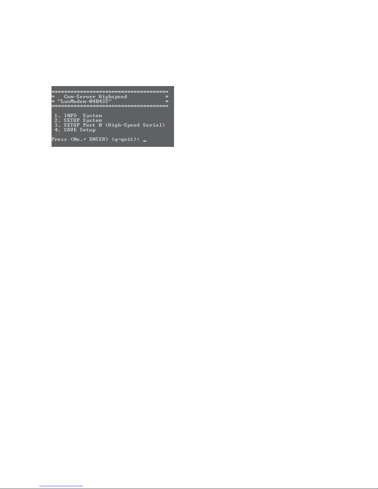
After successful opening of a connection and entering the
system password (if configured) you are taken to the main
menu of the LAN-Modem network stack.
To navigate enter the number of the desired submenu followed
by <Enter>. Entering <Enter> without preceding it by an
identifier returns you to the previous menu level.
All settings are first stored only temporarily. To save all settings
in non-volatile memory run 4. Save Setup in the main menu.
A1.2 Configuration of the TCP server port (Local Port)
Menu:
3. SETUP Port 0 -> 3. TCP/IP Mode -> Local Port
Default: 8000
This setting specifies under which TCP port number the LANModem can receive calls from a different LAN-Modem or virtual
modem port. If the value set here is other than 8000, the
corresponding target port number must be specified explicitly
along with the dial-up command (e.g.
ATD192.168.0.10,44555). For additional information about
specifying the port number in the AT dial-up command see the
section All AT Commands -> D(ATD).
Page 72

72
W&T Appendix
A1.3 Configuration of the System Name
Menu:
2. SETUP System -> 4. System Name -> Type System Name
The freely configurable system name consisting of max. 31
characters is used to identify the LAN-Modem. This name is
displayed as an opening message in the client for all Telnet
sessions.
The factory default setting for the system name is LanModem-
<wut1>, whereby the LAN-Modem replaces the keyword <wut1>
within communication with the last three places of the devicespecific Ethernet address. For example the factory set system
name of a LAN-Modem with Ethernet address 00:c0:3d:01:02:03
is LanModem-010203. When using DHCP protocol the system
name is also used for identification with respect to the DHCP
server.
A1.4 Configuration of the System Password
Menu:
2. SETUP System -> 3. System Password -> Type new password
The system password, which consists of any 31 (max.)
characters, protects against any subsequent configuration and
control access to the LAN-Modem.
· 1111: Telnet configuration menu
· 8888: Reset Com-Server
· IP assignment with WuTility
On Telnet port 1111 the system password is prompted as soon
as the connection is opened. For all other associated TCP ports
the password must be null-terminated (=[password] + 0x00)
and sent to the LAN-Modem no later than 2s after the TCP
connection has been established.
Page 73

73
W&T Appendix
Subject to error and alteration
A1.5 Configuration of Keep Alive Check
Menu:
2. SETUP System -> 1. Setup TCP/IP -> 9. Keep Alive Time (s)
Default: 5s
If the keep-alive check is activated by entering and saving a
value in second ticks, all TCP connections are monitored for
network-side data traffic. If there is no network traffic within the
set time, the LAN-Modem generates a keep-alive packet. If the
partner does not answer this packet, the connection is reset in
the LAN-Modem. This deletes any data still contained in the
serial in- and output buffers.
Example: During an existing connection over the internet the
DSL router drops out. After the set keep-alive time plus 2s for
two repetitions has elapsed, the LAN-Modem closes the
connection and is again ready for any other clients.
A1.6 Configuration of Link Speed
Menu:
2. SETUP System -> 8. Link Speed
Default: Autonegotiating
LAN-Modems are factory set for autonegotiation. Data
transmission speed and duplex procedure are automatically
negotiated with the connected switch/hub and set
correspondingly.
In addition to autonegotiation, the LAN-MOdem as well as many
manageable switches can be configured for fixed transmission
parameters with respect to speed and duplex procedure. To
prevent communications problems (duplex mismatch), only the
following two combinations are permitted:
Page 74

74
W&T Appendix
• Both parties (switch and LAN-Modem) are operated in Auto-
Negotiation mode.
• Both parties (switch and LAN-Modem) are configured for the
same (fixed) transmission speeds and duplex mode.
1
Changing the link speed is activated only after saving
and exiting the telnet or WBM session by means of an
automatic Com-Server reset. Data from any open network
connections is lost. If the newly selected setting is not supported
by the port used on the switch ort hub, the Com-Server may
then not be accessible.
Page 75

75
W&T Appendix
Subject to error and alteration
A2 Firmware update of the LAN-Modem
The LAN-Modem is divided into two function modules each with
their own update methods.
The AT command interpreter assumes all modem-specific tasks.
This include for example serial transmission, receiving and
executing the AT commands and monitoring the modem
connections opened thereby.
The network stack is responsible for handling all network-side
tasks, including the Ethernet level along with TCP and IP
protocols.
The two firmware components are in separate files and are sent
to the LAN-Modem independently of each other as described in
the following sections.
Firmware file extension AT command interpreter: *.mhx
Firmware file extension TCP/IP-Stack: *.uhd
A2.1 Where do I get the current firmware?
The most current firmware including update tools and a revision
list is published on our Web site at the following address:
http://www.wut.de
From there it is easiest to navigate using the Search function
located on the left side. In the entry field first enter the model
number of your device. Select Firmware in the associated
selection box and click on the Go button.
Page 76

76
W&T Appendix
This takes you directly to the page with the most up-to-date
firmware for your the LAN-Modem.
If you do not know the model number, you can find it on the
sticker located on the narrow side of the enclosure, likewise the
Ethernet address.
Type no.
58xxx [description]
EN=00c03d004a05
OK xxxxxx
Description, e.g. TB-number
for special versions
1
In particular if the sticker indicates an TB number as
the part number, it is possible that the LAN-Modem has a
special, customer-specific firmware or configuration. This
would be overwritten by uploading the standard firmware.
Please contact the responsible administrator in such cases
before the update.
Page 77

77
W&T Appendix
Subject to error and alteration
A2.2 Update des AT-Kommando-Interpreters
The update of the command interpreter can be done through
the serial port or over the network.
A2.2.1 ... via the serial interface
For this the LAN-Modem must have a serial connection to a terminal program whose transmission parameters are configured
as follows:
Baud rate: same as the LAN-Modem
Data format: 8 data bits, no parity, 1 stop bit
Handshake: RTS/CTS (required)
The command AT** is used to place the LAN-Modem in serial
update mode, which is acknowledged with the following
message:
MB90F562 bootloader v1.x W&T xx/xxxx
Invoked by software, ESC to cancel
Waiting (Port 0)...
1
The update mode is protected with a timeout of 30s. If no
data are transmitted within this time, the LAN-Modem
automatically resumes normal operating mode.
The function Send text file of the terminal program can now be
used to sent the mhx-file with the current firmware. The LANModem sends a continuous byte counter during the
transmission and returns the message OK after successful
completion of the update. The new firmware version can now
be checked using the command AT13.
1
You cannot use the binary data transmission function
offered by terminal programs, since this uses additional
protocols such as ZModem or Kermit.
Page 78

78
W&T Appendix
A2.2.2 ... via the network
Updating the firmware over the network offers the advantage of
a higher speed compared with the serial method. The
prerequisite however is that network-side remote maintenance
be enabled by the command %N1.
After establishing a TCP socket connection to Port 8000 on the
LAN-Modem, the latter returns a short identifier. If this is replied
to within three seconds with the character „U“, update mode is
started with the following message.
MB90F562 bootloader v1.x W&T xx/xxxx
Invoked by software, ESC to cancel
Waiting (Port 1)...
As in the case of a serial update, the LAN-Modem now expects
the update data in S record format. Under Windows the
following method using a Telnet client and pasting from the
clipboard has proven useful.
Example with Telnet client under Windows
1. Open the mhx file with the LAN-Modem firmware in an editor
and copy the entire contents to the clipboard.
2. From Start r Run r telnet [IP address] 8000 on a Windows
machine having a TCP/IP stack, the network connection to
the LAN-Modem is established and the message Wxxxx
appears.
3. Entering a U within the first three seconds activates update
mode, and the LAN-Modem sends the corresponding reply.
The serially connected device is informed of the access with
a short message.
1
The update mode is protected with a timeout of 30s.
If no data are transmitted within this time, the LAN-
Modem automatically resumes normal operating mode.
Page 79

79
W&T Appendix
Subject to error and alteration
4. Use Edit r Paste to copy the firmware from the clipboard to
the LAN-Modem.
5. After a successful update the LAN-Modem breaks the TCP
connection. Any transmission errors are reported with
referenced to a checksum error.
Page 80

80
W&T Appendix
A2.3 Update of the TCP/IP-Stack
Required is a PC running Windows 9x/NT/2000/XP with a
network connection and activated TCP/IP stack. For the update
process you need two files which, as already mentioned, are
available for download from our Web site at http://www.wut.de.
• The executable update tool for transferring the firmware to
the LAN-Modem.
• The file with the new firmware for transferring to the LANModem.
It is not necessary to do any special preparation in the LANModem for a firmware update. You only need to close all data,
control and configuration connections.
Highlight the desired LAN-Modem in the WuTility inventory list.
The Firmware button starts the Update dialog box in which you
must specify the file name of the new firmware (*.uhd). After
checking the compatibility of the specified firmware for the
selected LAN-Modem, WuTility activates the Next button which
starts the actual file upload.
1
Never interrupt the update process by pulling the power
plug or pressing the reset button. The LAN-Modem will be
non-operational after an incomplete update.
A2.3.1 Update in routed/protected environments
The WuTility Update Wizard divides itself on the network side
into three steps, whereby the specified TCP and UDP services
are used:
Page 81

81
W&T Appendix
Subject to error and alteration
1. Identification/Inventory of the device
Destination port LAN-Modem: UDP/8513
2. Initialization of the update process
Destination port LAN-Modem: TCP/ 8002
3. Upload firmware
Destination port LAN-Modem: UDP/69 (TFTP)
The previously described automatic processing of the update
requires that any security components (firewalls, routers ...)
used between WuTility and the LAN-Modem allow transparent
communication via these services.
1
When enabling the listed services in firewalls, routers etc.
various aspects of network security need to be taken into
consideration. These should therefore be run only after
consulting with the responsible network administrator.
Increasing complexity of the network structure brings with it
the risk of transmission problems, so that we recommend only
performing firmware updates from the computer located in the
same subnet as the LAN-Modem.
Page 82

82
W&T Appendix
A3 Reading/Sending Configuration Profiles
To simplify the configuration of the LAN-Modem when using a
greater number of devices, it is possible to copy the
configuration data. To do this, you must first configure a LANModem for the desired operating mode using the AT
commands. In the ext step you use &Wn to save these
configuration data in one of the two non-volatile profiles. Then
use the command &V2 to read the entire conofiguration in S
record format and store it in a file.
The upload of the configuration data to other LAN-Modems can
be done either over the serial interface or over the network. The
procedure is then identical to the update of the the AT
command interpreter.
Page 83

83
W&T Appendix
Subject to error and alteration
A4 Software reset of the LAN-Modem
Socket 8888 has been implemented in case the LAN-Modem
ever needs to be completely reset. If a connection is opened on
this port, the LAN-Modem immediately closes it again and then
performs a software reset.
Use of the system password
If a system password has been configured (see section
Extended configuration of the LAN-Modem), this must be nullterminated (=[password] + 0x00) and sent to the LAN-Modem
2s after a connection has been successfully opened. If the LANModem does not receive a correct or even any password within
this time, it sends the message PASSWD? followed by a null byte
(0x00) to the client and closes the TCP connection.
If no system password is configured, then as the example
shows the LAN-Modem immediately closes the TCP connection
as soon as it has been established and performs a port reset.
1
Following this reset all the buffer contents are deleted
and any still active connections are closed - the LAN-Modem is in its base state! This reset can be performed from any
station and should be done only in extreme cases!
Page 84

84
W&T Appendix
A5 The Modem Protocol on the TCP Level
Normally LAN-Modems will be used only to connect to each
other. It is however conceivable that an application program
uses TCP/IP programming to direct dial an individual LAN-Modem or to be called by the LAN-Modem. The information
required for doing this can be obtained on request.
Page 85

85
W&T Appendix
Subject to error and alteration
A6 Used ports and network security
The port numbers factory set in the LAN-Modem:
Password
protection
no
yes
yes
yes
yes
yes
yes
no
no
yes
Port
number
8000 (TCP)
1111 (TCP)
9084 (TCP)
8888 (TCP)
8002 (TCP)
8003 (TCP)
8004 (TCP)
8512 (UDP)
8513 (UDP)
161 (UDP)
Application
Port for incoming calls
TELNET Configuration port
Reset Port Status
Reset LAN-Modem
Initialize firmware
upate TCP/IP stack
Read Configuration data
Write configuration
data
Inventory
(replaces through port 8513)
Inventory
SNMP
Configurable?
yes
no
no
no
no
no
no
no
no
no
The following port numbers are deactivated with the factory
defaults. They will be used in case of a firmware update.
Port
number
69 (UDP)
Application
Update TCP/IP stack
Configurable?
no
Password
protection
yes
1
Each port number may be used for just one service in
the Com-Server. If differing numbers are used for
changeable ports, be sure that these are not assigned in
duplicate.
The LAN-Modem and network security
Network security has rightly taken on added significance in
recent times. All the experts are in agreement that there can be
no such thing as absolute security given today’s level of
technology. Every customer must decide for himself what the
appropriate balance is between security, functionality and cost
for his specific circumstances.
Page 86

86
W&T Appendix
In order to provide the customer with the greatest possible
flexibility which is oriented towards changing security
requirements from a pure testing and installation environment
to critical production applications, the safety measures have
been made highly customer-configurable. The present
document provides an overview of the safety measures which
have been implemented and can be used on the LAN-Modems.
It is presumed here that the original W&T firmware (without any
customer modifications) is being used. Additional details can
be found in the respective sections of this manual.
The authorization concept of the LAN-Modem
Control and configuration access to the LAN-Modems is
protected by the system password. The factory default setting
is for no system password, so that anyone logging in has full
access to the corresponding settings and functions. To prevent
unauthorized access, it is therefore recommended that a
system password be used. Additional measures in this regard,
such as the composition and regular changing of this
password, should be taken by the customer in an organizational
way.
The system password is transmitted to the LAN-Modem without
encoding. It must therefore be ensured if necessary that
password-protected access can be gained only over an Intranet
which the customer deems to be safe. For access over the
public Internet, additional measures such as the addition of a
VPN tunnel (Virtual Private Network) should be taken. This is
however a general issue for network security for which each
customer must find the appropriate solutions.
Ports with special functions
In addition to access over Telnet, there are a variety of
functions which can be activated over various TCP or UDP ports.
These are shown in the previous table. Details can be found in
the indicated sections of this manual.
Page 87

87
W&T Appendix
Subject to error and alteration
• SNMP
In order to be able to incorporate the LAN-Modems into an
SNMP-based network management, all the essential
configuration settings are also accessible via SNMP. This
access is protected in that the system password must be
used as a community string.
• Inventarisierungstool
Like all intelligent components from W&T, the LAN-Modems
can be accessed through the WuTility tool. Information is
read from UDP ports 8512 and 8513. The ports cannot be
turned off. No writing can be done over this path.
• Firmware update of the TCP/IP stack
(see section on Firmware-Update of the LAN-Modem)
Initialization of a firmware update takes place on the system
password-protected TCP port 8002. Only the TCP/IP stack
of the LAN-Modem is updated after an initialization on port
8002. The configuration data (IP address, gateway, serial
parameters, modes, etc.) are retained.
• Reading/writing the configuration data
The WuTility tool as well as a customer’s own applications
can be used to read and write the TCP/IP stack’s
configuration profile. Both of the TCP ports 8003 and 8004
used for this are protected by the system password.
• LAN-Modem Reset
(see section on Reset the LAN-Modem)
The TCP port 8888 allows a reset of the LAN-Modem. The
port is not configurable and is protected by the system
password.
Page 88

88
W&T Appendix
A7 Technical Data
Supply voltage ...
... DC
... AC
Current draw
Permissible ambient temperatur ...
... storage
... operation, non-cascaded
... operation, cascaded
Permissible relative humidity
Network
Galvanic isolation
Dimensions
Weight
Serial port
Baud rates
Data formats
Flow control
12V - 48V (+/-10%)
9Vrms - 30Vrms (+/-10%)
typ. 190mA @12VDC
-40 ... +70°C
0 ... +60°C
0 ... +50°C
0 - 95% (not condensing)
10/100BaseT, RJ45 for STP cables
min. 500Vrms
105 x 75 x 22mm
approx. 150g
1 x RS232 DCE on DB9/Female
1200 to 57.600 kBit/s
7, 8 Data bits, 1, 2 Stop bits,
NO, EVEN, ODD parity
Hardware handshake or
Xon/Xoff protocol
Page 89

89
W&T Appendix
Subject to error and alteration
 Loading...