

Page 1

Manual
Com-Server Highspeed
Release 2.10, October 2006
Type 58631, 58641,
58633, 58031,
58034, 58231,
58431, 58432,
58331, 58334
Com-Server Firmware 1.52 or higher
W&T
Page 2

W&T
© 10/2006 by Wiesemann und Theis GmbH
Subject to error and alteration:
Since it is posssible that we make mistakes, you mustn’t use
any of our statements without verification. Please, inform us
of any error or misunderstanding you come about, so we can
identify and eliminate it as soon as possible.
Carry out your work on or with W&T products only to the
extent that they are described here and after you have
completely read and understood the manual or guide. We are
not liable for unauthorized repairs or tampering. When in
doubt, check first with us or with your dealer.
Page 3

W&T
Introduction
The Com-Server models 58631, 58641, 58633, 58031, 58034,
58231, 58431, 58432 58331 and 58334 represent a uniform
platform for linking serial interfaces such as RS232, RS422/485
to TCP/IP networks.
In addition to all the standard applications implemented in
the Com-Servers, this reference manual also describes
methods of integrating Com-Servers into your own
applications.
Com-Server Highspeed models
Model
No.
58631
58631/UL
58641
58633
58031
58034
58231
58431
58432
58331
58334
Supply
voltage
12 - 24V
AC/DC
12 - 24V
DC
PoE or
24V AC/DC
12 - 24V
AC/DC
100-250V~
50-60Hz
100-250V~
50-60Hz
5V +/-5%
5V +/-5%
5V +/-5%
5V +/-5%
5V +/-5%
Network
interface
10/100BaseT
autosensing
10/100BaseT
autosensing
10/100BaseT
autosensing
10/100BaseT
autosensing
10/100BaseT
autosensing
10/100BaseT
autosensing
10/100BaseT
autosensing
10/100BaseT
autosensing
10/100BaseT
autosensing
10/100BaseT
autosensing
10/100BaseT
autosensing
Serial interface
1 x Interface module
RS232/RS422/RS485
1 x Interface module
RS232/RS422/RS485
1 x Interface module
RS232/RS422/RS485
3 x Interface module
RS232/RS422/RS485
1 x Interface module
RS232/RS422/RS485
4 x Interface modules
RS232/RS422/RS485
1 x Interface module
RS232/RS422/RS485
1 x TTL (optional
RS232, RS422/485)
1 x TTL + RS485 2-wire
(optional RS232, RS422)
1 x Interface module
RS232/RS422/RS485
4 x Interface modules
RS232/RS422/RS485
Housing
Top hat rail
housing
Top hat rail
housing
Top hat rail
housing
Top hat rail
housing
Desktop metal
housing
Desktop metal
housing
Compact metal
housing
none (OEM)
none (OEM,
credit card format)
19" version
19" version
Page 4

W&T
Content
1 Quickstart 9
1.1 Flow chart – Network installation using WuTility 10
1.2 Overview of configuration menu 11
1.3 Factory Default settings 12
2 Assigning the IP address 13
2.1 Configuring network parameters with WuTility 14
2.2 Assigning the IP using the ARP command 18
2.3 Serial assigning of IP, subnet mask and gateway 20
2.4 Assigning the IP using DHCP protocol 24
2.5 Assigning the IP using BOOTP protocol 28
2.6 Assigning the IP using a RARP server 30
3 Form factors 31
3.1 Com-Server Highspeed Industry 32
3.2 Com.Server Highspeed Isolated 58633 33
3.3 Com-Server Highspeed Office 34
3.4 Com-Server Highspeed 19“ 35
3.5 Com-Server Highspeed OEM 58431 36
3.6 Com-Server Highspeed compact 58231 37
4 Supply voltage 39
4.1 Com-Server Highspeed Industry and Isolated 40
4.2 Com-Server Highspeed Industry 58631/UL 41
4.3 Com-Server Highspeed Industry PoE 42
4.4 Com-Server Highspeed Office 43
4.5 Com-Server OEM and compact 44
4.6 Com-Server Highpeed 19“ 45
5 Interfaces and displays 47
5.1 Ethernet connection 48
5.2 RS232/422/485 combi-module 50
5.2.1 Opening the Com-Server 50
5.2.2 Mode selection 51
5.2.3 RS232 mode (factory default) 51
5.2.4 RS422/485 mode 53
Page 5

5
W&T
Subject to error and alteration
5.3 Interface for the OEM-Com-Server 58431 56
5.4 Option: 20mA interface 58
5.5 Interfaces for the OEM-Com-Server 58432 60
5.5 LED displays 63
6 Configuration access to the Com-Server 65
6.1 Configuration menu structure 66
6.2 Configuration via Telnet 68
6.3 Configuration via Browser - Web Based Management 71
6.3.1 Activating WBM with the WuTility-Tool 71
7 The basis configuration of the Com-Server 77
7.1 Saving your settings 78
7.2 Menu: INFO System 79
7.3 Menu: SETUP System 80
7.3.1 Menu: SETUP System r Setup TCP/IP 80
7.3.2 Menu: SETUP System r Telnet Password 83
7.3.3 Menu: SETUP System r System Password 84
7.3.4 Menu: SETUP System r System Name 85
7.3.5 Menu: SETUP System r Flash Update 85
7.3.6 Menu: SETUP System r Factory Defaults 86
7.3.7 Menu: SETUP System r Reset 86
7.4 Menu ... r TCP/IP Mode r System Options 87
8 Configuration of the serial port 89
8.1 The serial parameters (Menu: UART Setup) 90
8.1.1 Baud rate, Data bits, stop bits, parity 90
8.1.2 The handshake modes 91
8.1.3 FIFO Send/Rec 96
9 The protocol stack of the Com-Server 97
9.1 Services of the Com-Server 98
9.2 Addressing in the TCP/IP Network 99
9.3 The protocol stack of the Com-Server 100
9.3 1 Data transfer per TCP/IP and UDP/IP sockets 100
10 Data transfer per TCP/IP sockets 103
10.1 The Com-Server as TCP server 104
10.1.1 Configuration of the local port number 104
10.1.2 Optional settings 105
Page 6

W&T
10.2 The Com-Server as TCP-Client 107
10.2.1 TCP client mode with fixed destination system 108
10.2.2 TCP client mode with serial addressing 111
10.2.3 Optional settings 112
10.2.4 Deactivating TCP client mode 114
10.2.5 Application:
Client/Server mode between Com-Server-Ports 114
11 Data transfer per UDP 117
11.1 The Com-Server as UDP peer 118
11.1.1 Setting the local UDP port number 119
11.1.2 UDP clientmode with fixed destination system 120
11.1.3 UDP client mode with serial addressing 121
11.1.4 Optional settings 123
11.1.5 Deactivating UDP mode 124
12 The Windows COM port redirector 125
12.1 Virtual COM ports 126
13 Box-to-Box mode 129
13.1 Box-to-Box mode 130
13.1.1 Configuring Box-to-Box mode 131
13.1.2 Optional settings 132
13.1.3 Deactivating Box-to-Box mode 132
14 Data transfer per FTP 135
14.1 The Com-Server as FTP server 136
14.2 The Com-Server as FTP client 138
14.2.1 Configuring the destination address and port no. 138
14.2.4 Deactivating FTP client mode 145
14.2.5 Application examples 145
15 Data transfer per Telnet 147
15.1 Com-Server as Telnet server 148
15.2 The Com-Server as Telnet client 149
15.2.1 Optional settings 151
15.2.2 Deactivating Telnet client mode 151
Page 7

W&T
16 IP Bus mode 153
16.1 Function of the IP Bus mode 154
16.2 Configuring the IP Bus mode 155
16.2.1 Activating the master 155
16.2.3 Deactivating IP Bus Mode 156
17 The Com-Server as SLIP router 157
17.1 Configuring the SLIP mode 158
18 Serial Socket Interface 163
18.1 Serial Socket Interface 164
19 Status and error messages 165
19.1 Menu Setup Port x r Port State 166
20 Expanded services of the Com-Server 169
20.1 The control port 170
20.2 Reset Com-Server-Port 178
20.3 Software reset of the Com-Server 180
20.4 Uploading/downloading configuration data 181
20.5 Inventory taking per UDP/8513 183
20.6 SNMP management 186
21 Firmware update of the Com-Server 187
21.1 Where do I get the current firmware? 188
21.2 Network firmware update under Windows 189
21.3 Network firmware update under UNIX 190
Appendix 193
TCP/IP under Windows 9x 194
TCP/IP under Windows NT 195
Used ports and network security 196
Serial assignment of the IP address under Windows 200
Web application HTTP, SMTP, POP3 ... 204
WuTility - Inventory and management tool 206
Hardware reset to factory defaults 207
Technical Data 208
Declaration of conformity 215
Index 216
Page 8

W&T
Page 9

9
W&T
Subject to error and alteration
1 Quickstart
Already experienced users of Com-Servers will find on the two following
pages a flow chart with the essential steps for start-up as well as a
complete overview of the configuration menu. Detailed information can
be found then in the following sections.
Page 10
10
W&T
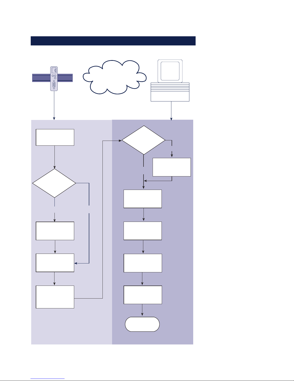
1.1 Flow chart – Network installation using WuTility
Select site
Connect
supply voltage
Com-Server Windows PC
with TCP/IP
WuTility
installed?
yes
Connect
network cable
Finish
Network
no
Obtain IP-
address, subnet
mask, gateway
address
Install
WuTility with
product CD
Button:
IP address
Enter IP address
subnet mask,
gateway
Start
WuTility
Select
device in
inventory list
Com-Server
with PoE?
no
yes
Page 11

11
W&T
Subject to error and alteration
1.2 Overview of configuration menu
SETUP System Setup TCP/IP
Telnet Password
System Password
System Name
Flash Update
Factory Defaults
Reset
Link Speed (Auto, 10/100BT, HD/FD)
SETUP Port 0
SETUP Port 1
SETUP Port 2
SETUP Port 3
SAVE Setup
TCP Client
UDP Client
Serial Socket
Interface
Telnet Client
FTP Client
Box to Box
(TCP)
IP Bus Mode
SLIP Router
System Options
Server Port
Server IP/URL
Special Options
Port State
UART Setup
TCP/IP Mode
Connection State
Error State
Clear Port Mode
Baud
Parity
Data Bits
Stopbit
Handshake
FIFO S/R:
Standard Baudrates
Special Baud Divisor
230,4k
172,8k
115,2k
57600
38400
19200
9600
4800
2400
1200
600
300
150
110
757200
50
NONE
EVEN
ODD
8
7
None
Hardware
Software
Special
1
2
Pin: RTS
Pin: DTR
Pin: CTS
Pin: DSR
XON/XOFF
XON/XOFF (Filter)
FIFOs OFF
FIFOs ON
disable
8/8
16/16
32/56
56/60
Local Port TCP/UDP Inactivity Timeout
Connect. Timeout
Disconnect Char
Dispatch String 1
Dispatch String 2
Client: "C"+Addr
Response Mode
Server Port
Server IP/URL
Special Options
Serial Coding
Serial Protocol
Dispatch String 1
Dispatch String 2
Client: "C"+Addr
Disconnect Char
Write: "C"+Addr
Serial Protocol
Serial Coding
Protocol Char
Server Port
Server IP/URL
Special Options
Disconnect Char
Inactivity Timeout
Serial 0d -> 0d00
Server Port (21)
Server IP
Special Options
Auto FTP
FTP Client Login
Inactivity Timeout
Connect. Timeout
Protocol Char
Server Port
Server IP/URL
Special Options
Server Port (21)
Server IP
Special Options
Dispatch String 1
Dispatch String 2
Slave: Master IP
Master: Subnet IP
Net Address
SLIP-Net Routing
Network Delay
Flush Buffer
Telnet Echo
(Highspeed
Serial)
Logout
Retransm. Timeouts
INFO System Cable Type
MAC address
SOFTW Date/REV
HARDW Rev
Run Time
IP-Address
Subnet Mask
Gateway
MTU (560-1460)
BOOTP Client
Keep Alive Time
Standard Gateway
Route 1
Route 2
Route 3
Route 4
Destination
Netmask
Gateway
WBM Port
DNS Server
DHCP Client
Control Port TCP
To activate the new settings
always save using SAVE Setup
with Telnet or the LOGOUT
link on the webpages
Page 12

12
W&T
1.3 Factory Default settings
The list contains an overview of the most important settings.
For many applications, such as the W&T COM Port Redirector,
no additional configurations need to be made besides
assigning the network base parameters. Detailed information on
the respective parameters can be found in later sections of this
manual.
Network settings
Hardware connection: Auto negotiating
IP address: 0.0.0.0
Gateway address: 0.0.0.0
Subnet mask: 255.0.0.0
DNS server: 0.0.0.0
DHCP: Active
1
To prevent unintended address assignments or changes,
we recommend deactivating the DHCP, BOOTP and RARP
protocols if they are not expressly used in the respective
network environment.
Serial settings
Hardware connection: RS232
Baud rate: 9600
Data bits: 8
Parity: NO
Stop bits: 1
Handshake: Hardware (RTS/CTS)
FIFO: OFF
Configuration access
Per Telnet using TCP port 1111
Network applications/Operating modes
TCP sockets (Port A...D): 8000, 8100, 8200, 8300
Telnet (Port A...D): 6000, 6100, 6200, 6300
FTP (Port A...D): 7000, 7100, 7200, 7300
Page 13

13
W&T
Subject to error and alteration
2 Assigning the IP address
The Com-Server is factory set to IP address 0.0.0.0. Before you can make
the entry in the Com-Server, you need to specify an IP address that is valid
for your network. You system administrator will provide you with this. If
you have only a small network with no routing, use the IP address of your
PC and simply change the last digit. The IP address must be unique within
the network!
. Assigning IP address, subnet mask and gateway address
using WuTility management tool
. Using the ARP command
. Assigning IP address, subnet mask and gateway address
through the serial port
. Using the RARP protocol
. Assigning IP address, subnet mask and gateway using
DHCP/BOOTP protocol
Page 14

14
W&T Assigning the IP address
2.1 Configuring network parameters with WuTility
The Windows tool WuTility version 3.0 and higher allows not
only inventorying of Com-Server and Web-IO installations, but
also convenient assignment of the following network-side basic
parameters:
• IP address
• Subnet mask
• Gateway address
• Activating/deactivating BOOTP/DHCP
• Activating/deactivating Web-Based-Management
Assigning requires that the PC and Com-Server be in the same
subnet. In firmware revision 1.45 the function is independent
of the current address settings in the Com-Server, i.e. even
changes to parameters not matching the network are easily
made. Any system password which has been set must however
in this case be known.
Downloading and installing WuTility
The most current version can always be found at our Web site
under the following address:
http://www.wut.de
From there use the menu tree on the left side to navigate:
Products & Downloads r Com-Servers r Software Tools
After unzipping the ZIP file, begin installation by doubleclicking on the file setup_us.exe. WuTility is started from
Start r Programs r W&T Software Toolkit r WuTility
Starting the assignment dialog
First be sure that both the Com-Server and the computer you
are using are connected to the same network and are in the
same subnet. When started, WuTility automatically searches the
Page 15
15
W&T Assigning the IP address
Subject to error and alteration
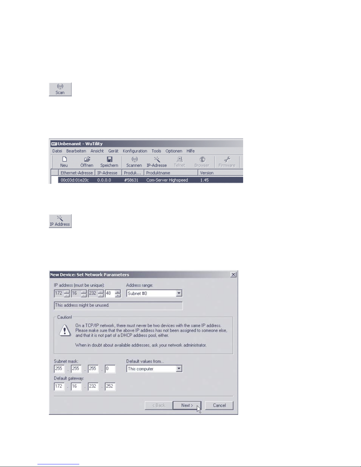
local network for connected W&T network devices and creates
an inventory list. This search process can be repeated manually
as often as desired by clicking on the Scan button:
Within the inventory list you can identify the desired Com-Server based on its MAC address. For initial installations its IP
address is 0.0.0.0.
Select the Com-Server and click on the IP address button:
Enter the desired values for IP address, subnet mask and
gateway address in the corresponding fields and then click on
the Next button.
Page 16
16
W&T Assigning the IP address
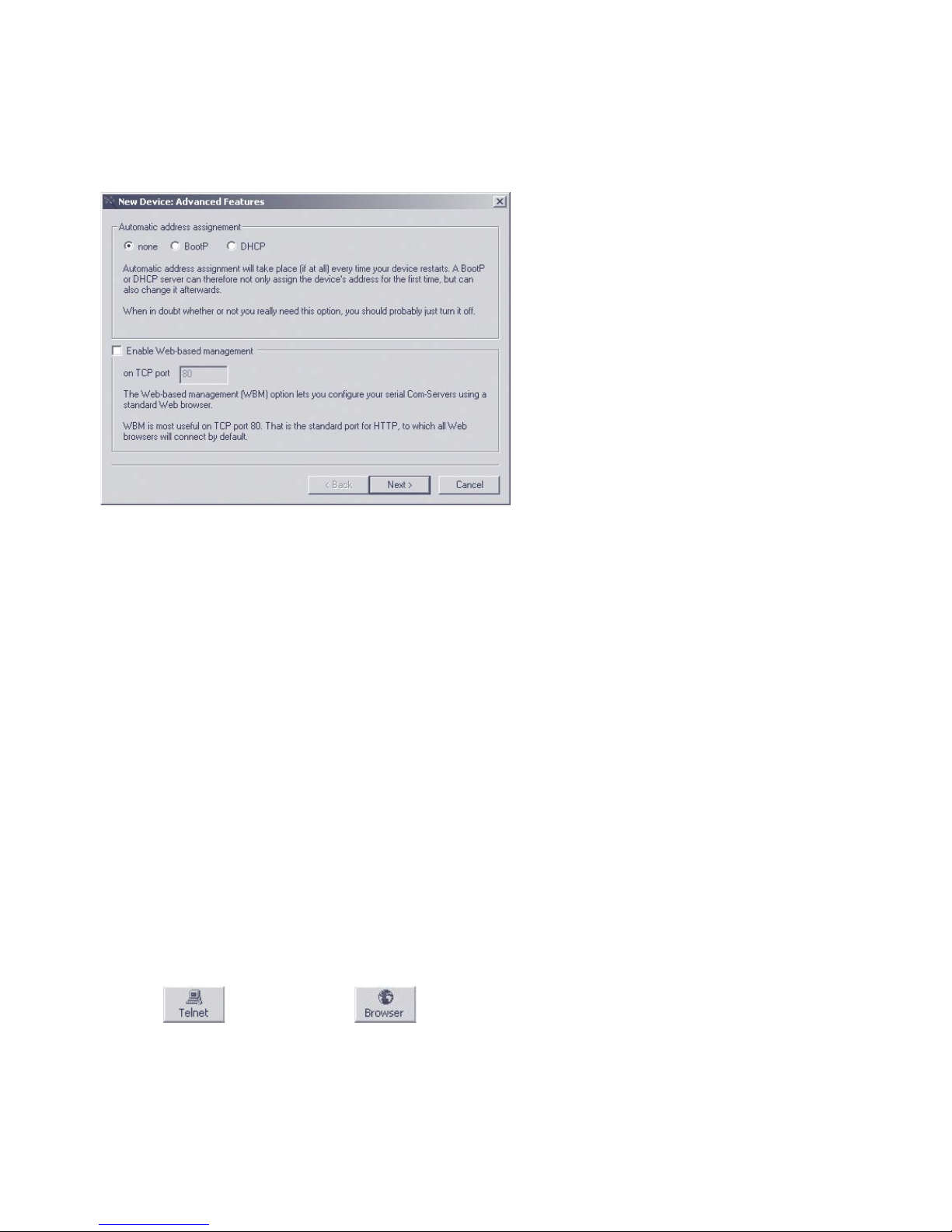
In the following window you can activate the BOOTP client and
the Web-Based-Management of the Com-Server.
1
To prevent unintended address assignments or changes,
we recommend deactivating the DHCP, BOOTP and RARP
protocols if they are not expressly used in the respective
network environment. Com-Servers with incorrectly assigned IP
addresses can be easily found after the fact using the scan
function of the WuTility management tool and reconfigured.
Clicking on the Next button assigns the network parameters to
the Com-Server. All columns in the WuTility device list are filled
with information.
This concludes the network-side startup of the Com-Server, and
for many applications – such as use together with the COM Port
Redirector – no further settings are necessary. Special modes
or serial parameters can be set using the telnet configuration
menu or, if Web-Based-Management was used, with the help of
the Internet browser. To do this, click on either the Telnet or
Browser button:
Telnet:
Browser:
Page 17

17
W&T Assigning the IP address
Subject to error and alteration
1
Changing network parameters is protected by the
system password. To prevent improper access, we
recommend assigning a system password for any Com-Servers
in use.
Additional information can be found in the section
Configuration Accesses for the Com-Server.
Page 18

18
W&T Assigning the IP address
2.2 Assigning the IP using the ARP command
1
This method can only be used if the Com-Server
does not already have an IP address, i.e. the entry is
0.0.0.0. To change an IP address, use one of the other
methods described in this section or use the configuration
menu over Telnet.
Required is a computer which is located in the same network
segment as the Com-Server and which has TCP/IP protocol
installed. Read off the Ethernet address of the Com-Server
from the sticker on the side of the housing:
58xxx [Model]
EN=00c03d004a05
OK xxxxxx
Ethernet address
Insert a static entry into the ARP table of the computer using
the following command line:
arp -s [IP address] [MAC address]
e.g. under Windows:
arp -s 172.16.231.10 00-C0-3D-00-12-FF
e.g. under SCO UNIX:
arp -s 172.16.231.10 00:C0:3D:00:12:FF
Next use the following command line under Start r Run to
start a Telnet session on the configuration port of the ComServer with the desired IP address:
telnet 172.16.232.10 1111 [
Return
]
1
The IP addresses must be without leading zeros in
all Windows environments. Otherwise the entry is
incorrectly interpreted by the system and an incorrect IP
address is assigned to the Com-Server.
i
The IP address must
be unique within the
network.
i
Older Windows systems
only accept a static
entry if there is a
dynamic one already
present. Here you
should first ping
another network
station.
Page 19

19
W&T Assigning the IP address
Subject to error and alteration
The Com-Server takes the IP address of the first network packet
sent to it as its own and saves it in non-volatile memory. The
Telnet connection will be established and the configuration
menu is displayed in the Telnet window. All further settings are
made here (see Basic configuration of the Com-Server).
Page 20

20
W&T Assigning the IP address
2.3 Serial assigning of IP, subnet mask and gateway
After a Com-Server reset a time window of around 1-2
seconds is available, during which you can assign a new IP
address, subnet mask and gateway address by entering at
least 3 „x“.
1
In contrast to the ARP method described above, this
serial method functions regardless of whether the
Com-Server already has an IP address or not. The procedure
can be repeated as often as desired. Therefore use this
method if you don‘t know the IP address or have forgotten it.
Appendix D contains the detailed procedure under Windows
using HyperTerminal.
First connect the serial port A of the Com-Server to a
computer. For a standard PC or laptop, you will need a
crossed RS232 cable (=Null modem cable, see RS232
interface).
The serial transmission parameters of the terminal program
you use should be set to 9600 baud, no parity, 8 bits, 1 stop
bit, no handshake. Reset the Com-Server by interrupting the
power. When the green status LED lights up, enter the letter
„x“ at least three times on the terminal, until the Com-Server
returns the prompt IPno.+<Enter>.
Use the usual format (xxx.xxx.xxx.xxx) to enter the IP
address, and end the entry by pressing <Enter>. If the entry
was accepted, the acknowledgement is the assigned IP
address. Otherwise you will get a FAIL message followed by
the last current IP address.
All other settings such as gateway address, subnet mask etc.
are done through the Telnet configuration menu (see Basic
configuration of the Com-Server).
Page 21

21
W&T Assigning the IP address
Subject to error and alteration
2.3.1 Assigning of subnet mask and gateway address
Together with the IP address, the subnet mask and gateway
address can also be assigned serially. The entry is separated
by commas and follows the IP address. Entering as shown in
the following example will assign IP address 172.17.231.99,
subnet mask 255.255.255.0 and gateway 172.17.231.52 to
the Com-Server
IP no.+<ENTER>: <- Com-Server
172.17.231.99,255.255.255.0,172.17.231.52 -> Com-Server
172.17.231.99,255.255.255.0,172.17.231.52-1 <- Com-Server
2.3.2 Deactivating DHCP/BOOTP/RARP
The DHCP/BOOTP/RARP function of the Com Server can be
turned off as part of assigning the IP address serially. We
recommend making use of this at all times except where use
of DHCP, BOOTP or RARP is expressly required. To deactivate
the DHCP/BOOTP/RARP client enter the option „-0“ (zero)
directly appended (no space!) to the IP address and confirm
with <Enter>.
• -0
DHCP, BOOTP and RARP = OFF
• -1
DHCP = OFF,
BOOTP and RARP = ON
• -2
DHCP = ON
BOOTP and RARP = OFF
Example: Deactivation of DHCP, BOOTP and RARP
xxx - > Com-Server
IP no.+<ENTER>: <- Com-Server
172.17.231.99-0 - > Com-Server
172.17.231.99 <- Com-Server
i
An explanation of the
basic terms and
concepts for
addressing in the
internet and using
DHCP and BOOTP can
be found in our
manual TCP/IP-
Ethernet and Web-IO.
Page 22

22
W&T Assigning the IP address
This function can later be reactivated through the Telnet
configuration under SETUP System r SETP TCP/IP r BOOTP
Client.
1
To prevent unintended address assignments or changes,
we recommend deactivating the DHCP, BOOTP and RARP
protocols if they are not expressly used in the respective
network environment. Com-Servers with incorrectly assigned IP
addresses can be easily found after the fact using the scan
function of the WuTility management tool and reconfigured.
2.3.3 Serial activation of Web Based Management
To further configure the Com-Server you can use either Telnet
protocol or an Internet browser, although only Telnet is an
option in the Com-Server as shipped from the factory. You can
activate Web Based Management as part of the serial IP
assignment. To do this, enter +w[Portno.] directly after the IP
address or address string. Here Portno. is the desired TCP port
in decimal format.
Example 1: Deactivating DHCP/BOOTP/RARP and activating Web
Based Management on TCP port 8080.
xxx - > Com-Server
IP no.+<ENTER>: <- Com-Server
172.17.231.99,255.255.0.0,172.17.231.52-0+w8080 -> Com-Server
172.17.231.99,255.255.0.0,172.17.231.52-0+w8080 <- Com-Server
Example 2: Activation of Web Based Management on TCP port
80. The status of DHCP/BOOTP/RARP remains unchanged.
xxx - > Com-Server
IP no.+<ENTER>: <- Com-Server
172.17.231.99+w80 -> Com-Server
172.17.231.99- 1 < - Com-Server
Page 23

23
W&T Assigning the IP address
Subject to error and alteration
1
For additional information on activating Web Based
Management, see section Configuration via Browser
Web Based Management.
Page 24

24
W&T Assigning the IP address
2.4 Assigning the IP using DHCP protocol
Many networks use DHCP (Dynamic Host Configuration
Protocol) or its predecessor described in the following section
for centralized and dynamic assignment of the network
parameters. DHCP protocol is activated by the factory default
settings, so that in network environments dynamic IP
assignment is sufficient for connecting the Com-Server to the
network. The following parameters can be assigned using
DHCP:
• IP address
• Subnet mask
• Gateway address
• DNS server
• Lease time
1
To prevent unintended address assignments or changes,
we recommend deactivating the DHCP, BOOTP and RARP
protocols if they are not expressly used in the respective
network environment. Com-Servers with incorrectly assigned IP
addresses can be easily found after the fact using the scan
function of the WuTility management tool and reconfigured.
2.4.1 Activating/Deactivating DHCP
The factory default setting is for DHCP protocol active. To
deactivate it or to enable it again later, use one of the following
options.
• Management-Tool WuTility
Select the desired Com-Server in the device list and click on the
IP Address button. In the first dialog box enter the newly
assigned network parameters and then click on Continue. In the
following dialog BOX deactivate the options BOOTP and DHCP.
Page 25

25
W&T Assigning the IP address
Subject to error and alteration
Clicking on Continue then sends the new configuration data to
the Com-Server.
• Serial port
As part of serial IP assignment, the following options for
deactivating/activating DHCP and BOOTP can be selected
directly following the address string:
-0 r Deactivates DHCP and BOOTP
-1 r Activates BOOTP/RARP
-2 r Activates DHCP
A detailed description of the procedure can be found in the
section on Serial assignment of IP, subnet mask and gateway.
• Telnet or Web Based Management
From the menu branch SETUP System r Setup TCP/IP r DHCP/
BOOTP Client the protocols can be alternately activated and
both deactivated. For detailed information refer to the section
Menu: SETUP System.
2.4.2 System Name
To support any automatic updating of the DNS system by the
DHCP server, the Com-Server identifies itself within the DHCP
protocol with its system name. The factory default setting for
this is COMSERVER_ followed by the last three places of the
Ethernet address. For example the factory set system name of
a Com-Server with the Ethernet address 00:c0:3d:01:02:03 is
COMSERVER_010203. The system name of the Com-Server can
be changed in the configuration. For additional information
refer to the section Menu: SETUP System r System Name.
Page 26

26
W&T Assigning the IP address
2.4.3 Lease-Time
The lease time determined and transmitted by the DHCP server
specifies the Time-To-Live of the assigned IP address. After half
the lease time has expired, the Com-Server attempts to extend
the time for the assigned DHCP server and up update the
address. If this is not possible by the time the lease time
expires, for example because the DHCP server can no longer
be reached, the Com-Server deletes the IP address and starts a
new cyclical search for alternate DHCP servers for the purpose
of assigning a new IP address.
Because of the absent clock, the lease time associated with the
current IP address is no longer available after a reset. After the
restart therefore a corresponding update request is issued with
the original DHCP server. If the latter is not resolvable at this
point in time, the Com-Server deletes the IP address and starts
a new cyclical search for alternate DHCP servers.
If DHCP is activated, the remaining lease time together with the
current IP address is displayed in the menu item SETUP System
r Setup TCP/IP r IP-Address using the format hh:mm:ss.
1
If after the assigned lease time has expired the DHCP
server is not reachable, the Com-Server deletes its IP
address. All existing TCP/UDP connections between the ComServer and other network clients are thereby closed. To prevent
such events, we recommend configuring the assigned lease
time in the DHCP server to infinite if possible.
Page 27

27
W&T Assigning the IP address
Subject to error and alteration
2.4.4 Reserved IP addresses
If the Com-Server is used as a TCP server or UDP peer, it
provides services which other clients in the network can also
make use of as needed. To open a connection, they of course
need the current IP address for the Com-Server, so that in such
situations it makes sense to reserve a particular IP address for
the Com-Server on the DHCP server. This is generally done by
linking the IP address to the unique Ethernet address of the
Com-Server, which can be found on the sticker attached to the
housing.
58xxx [Typ]
EN=00c03d004a05
OK xxxxxx
Ethernet-Adresse
2.4.5 Dynamic IP addresses
Fully dynamic address assignment, whereby the Com-Server
gets a different IP address every time it is restarted or after the
lease time has expired, only makes sense in network
environments with automatic cross-connection between the
DHCP and DNS services. This means when a new IP address is
assigned to the Com-Server, the DHCP server then
automatically updates the DNS system as well. The new address
is associated with the respective domain name. If in doubt,
consult your system administrator for detailed information
about your network environment.
If the Com-Server is configured as a TCP or UDP client and itself
actively searches for a connection to server services in your
network, dynamic changing IP addresses may be used.
Page 28

28
W&T Assigning the IP address
2.5 Assigning the IP using BOOTP protocol
Many networks use BOOTP as predecessor of DHCP protocol
for centralized and dynamic assignment of IP addresses. The
factory default setting is for BOOTP turned off. You can activate
it from SETUP System r SETUP TCP/IP r BOOTP Client. The
following parameters can be assigned:
• IP address
• Subnet mask
• Gateway address
• DNS server
1
To prevent unintended address assignments or changes,
we recommend deactivating the DHCP, BOOTP and RARP
protocols if they are not expressly used in the respective
network environment. Com-Servers with incorrectly assigned IP
addresses can be easily found after the fact using the scan
function of the WuTility management tool and reconfigured.
2.5.1 Address reservation
BOOTP protocol is based on fixed reservations of fixed IP
addresses for particular Ethernet addresses. This means a ComServer connected to the network only gets an IP address if the
latter was previously stored in the BOOTP server. Check with
your system administrator for creating this reservation. The
Ethernet address of the Com-Server can be found on the
housing sticker.
58xxx [Model]
EN=00c03d004a05
OK xxxxxx
Ethernet address
Once the administrator has made the necessary entries, the
Com-Server obtains the desired IP address automatically after
Page 29

29
W&T Assigning the IP address
Subject to error and alteration
each reset. To ensure accessibility of the Com-Server even
should the BOOTP server go down, the previous IP address is
retained should there be no reply.
Page 30

30
W&T Assigning the IP address
2.6 Assigning the IP using a RARP server
UNIX environments especially use RARP protocol for centrally
assigning IP addresses. TCP/IP devices that want to obtain an
IP address send RARP requests with their Ethernet address as a
broadcast over the network.
RARP protocol is coupled to BOOTP protocol in the Com-Server. Activate it from SETUP System r SETUP TCP/IP r BOOTP
Client.
Activate the RARP server, and enter the Ethernet address of the
Com-Server in the file /etc/ethers and the IP address in the file
/etc/hosts.
58xxx [Model]
EN=00c03d004a05
OK xxxxxx
Ethernet address
The Com-Server must be connected to the network in the same
segment as the RARP server.
Example:
Your Com-Server has the MAC address EN= 00C03D0012FF
(sticker on the unit). You want to give it IP address
172.16.231.10 and the alias name WT_1:
• Entry in the file /etc/hosts:
172.16.231.10WT_1
• Entry in the file /etc/ethers:
00:C0:3D:00:12:FF WT_1
1
To prevent unintended address assignments or changes,
we recommend deactivating the DHCP, BOOTP and RARP
protocols if they are not expressly used in the respective
network environment. Com-Servers with incorrectly assigned IP
addresses can be easily found after the fact using the scan
function of the WuTility management tool and reconfigured.
Page 31

31
W&T
Subject to error and alteration
3 Form factors
. Industry model
. Isolated model
. Office models
. 19“ models
. OEM models
. Compact model
Page 32
32
W&T Form factors
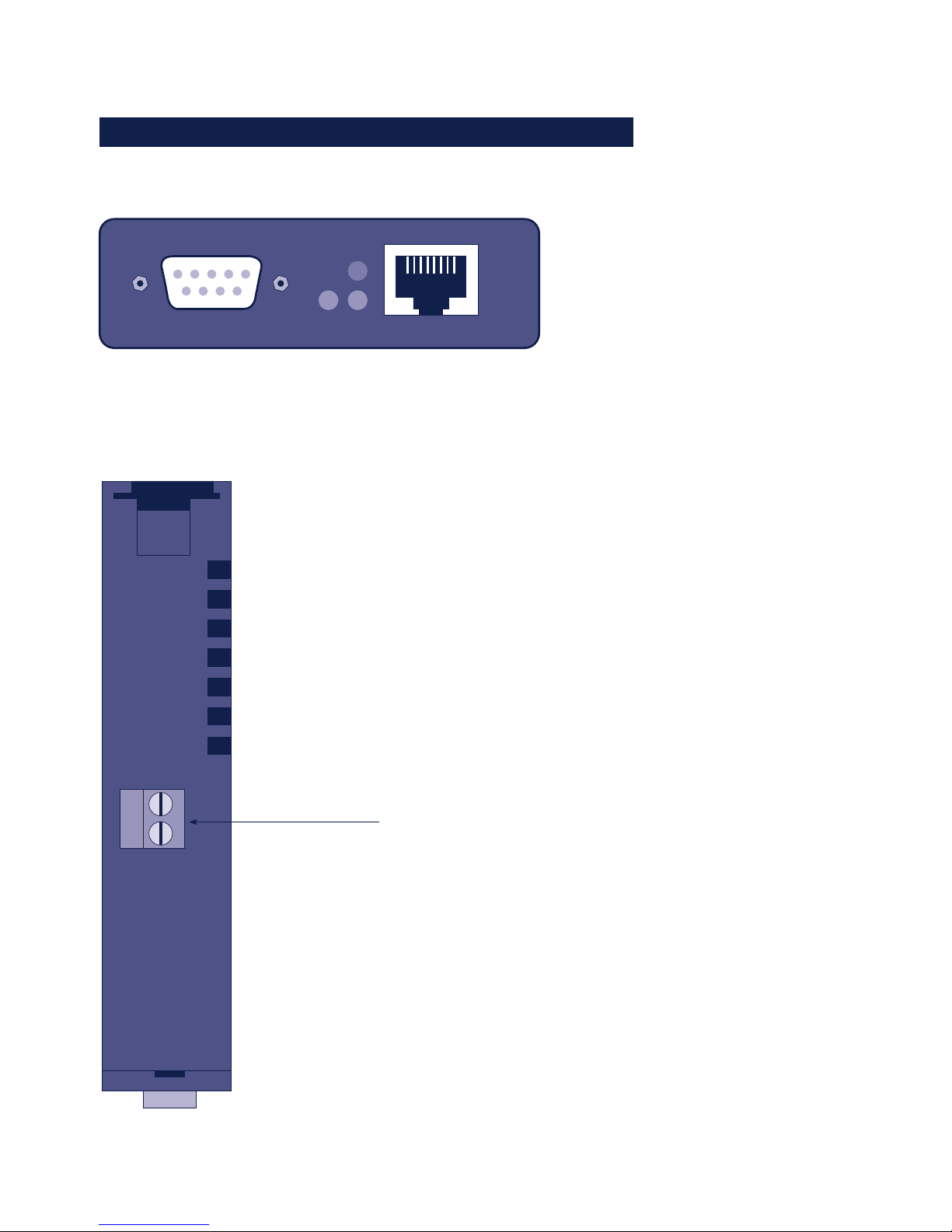
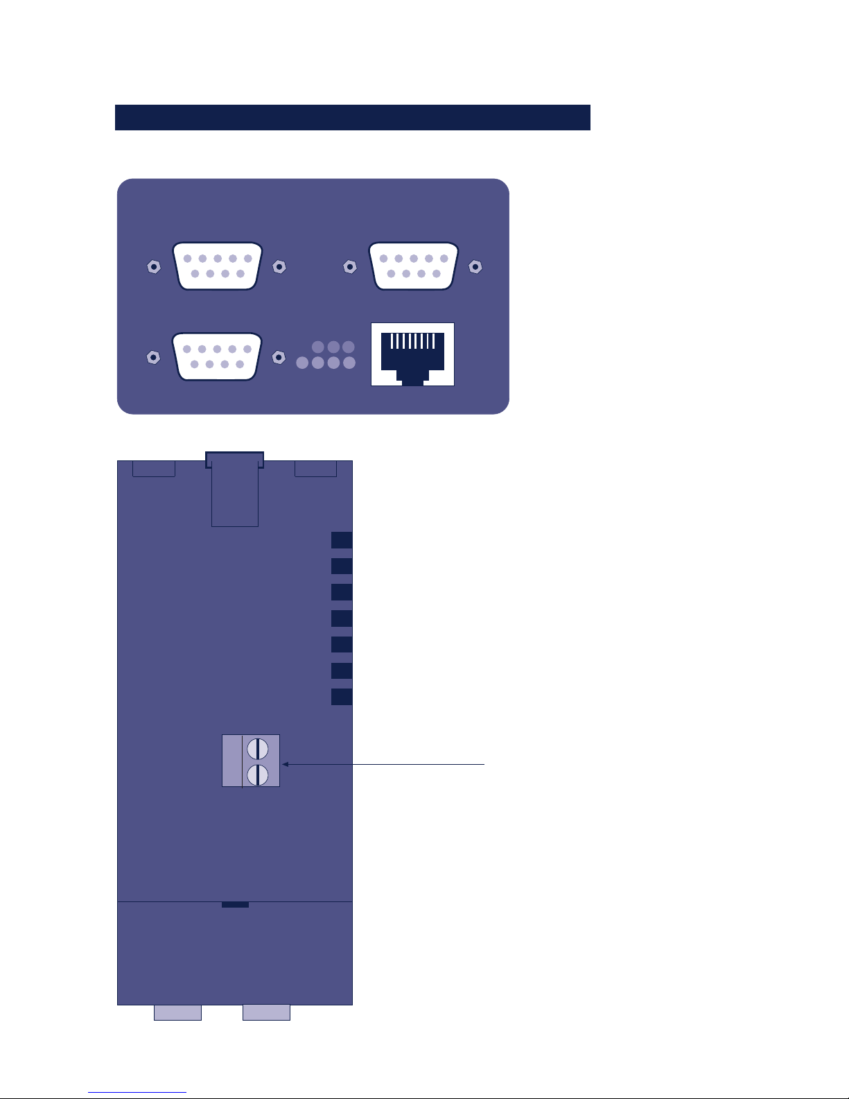
3.1 Com-Server Highspeed Industry
Front view 58631, 58631/UL, 58641
Serial Port
Power
Network
Status
Error
Bottom side 58631, 58631/UL, 58641
12-24V AC/DC
(for details see section
Supply voltage)
Screw terminal
supply voltage:
Page 33
33
W&T Form factors
Subject to error and alteration
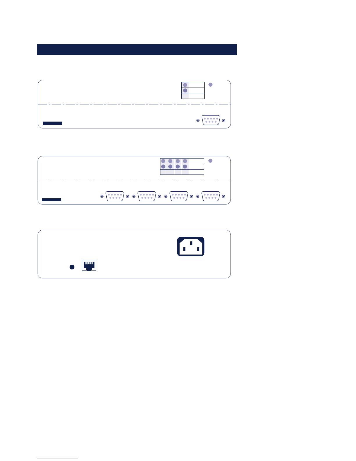
3.2 Com.Server Highspeed Isolated 58633
Frontview 58633
Power
Network
Status
Error
Serial Port A
Serial Port B
Serial Port C
Bottom Side 58633
Supply
voltage
12-24V =/~
Screwterminal
Page 34
34
W&T Form factors
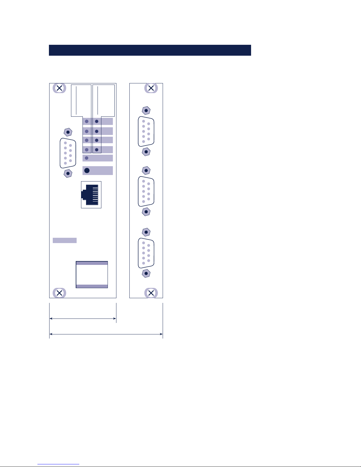
3.3 Com-Server Highspeed Office
Front view 58031
Power
A
Com-Server
Highspeed Office
10/100 MBit
#58031
W&T
www.wut.de
Serial Port A
Status
Error
Port
Front view 58034
Power
D C B A
Status
Error
Port
Serial Port D
Serial Port C Serial Port B Serial Port A
Com-Server
Highspeed Office
10/100 MBit
#58034
W&T
www.wut.de
Back view 58031, 58034
Reset
Network
Supply voltage
Page 35
35
W&T Form factors
Subject to error and alteration
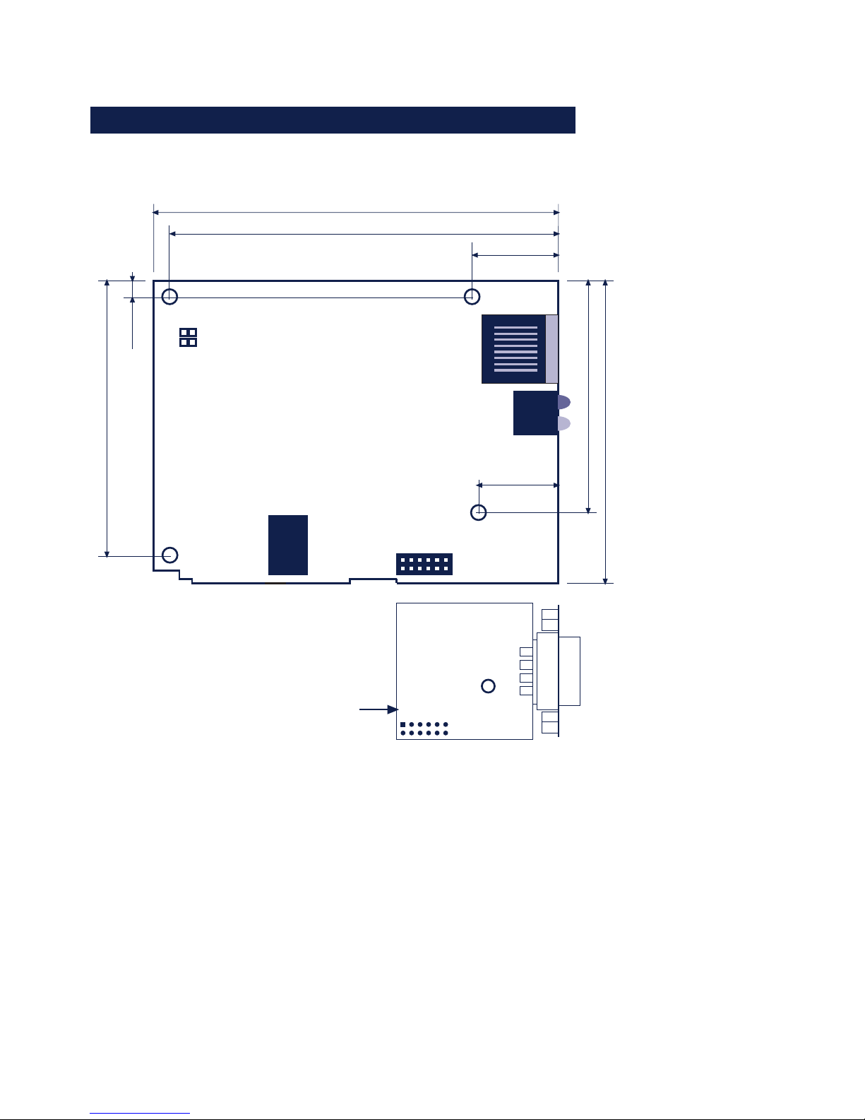
3.4 Com-Server Highspeed 19“
58331 / 8TE
58334 / 12TE
= check ser. data format
Status LED
Error LED
off1x2x
3x
= OK
= check network
= check ser. handshake
on = self test / update
offonblink
flash
= standby
= error
= connection
= data
Power
Reset
Port A
Port B
Port C
Port D
Serial Port A
W&T
www.wut.de
Com-Server
#5833x
10/100BaseT
Serial Port B Serial Port C Serial Port D
Page 36
36
W&T Form factors
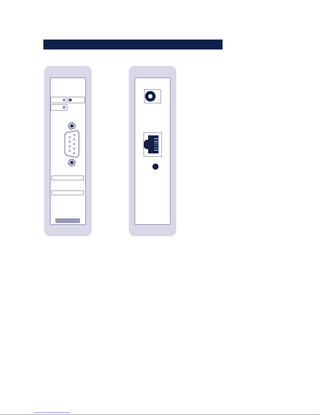
3.5 Com-Server Highspeed OEM 58431
95,8mm
71,1mm
17,2mm
56,23mm
D=4mm
92,13mm
64,48mm
3,7mm
20,38mm
D=3,5mm
D=3,5mm
D=3,5mm
Optional serial module:
RS232/422/485
RS232
RS422/485
J1
J2
Page 37
37
W&T Form factors
Subject to error and alteration
3.6 Com-Server Highspeed compact 58231
Status Error
Power
Serial Port
off
1x
2x
3x
on
= check network
= check ser. data format
= check ser. handshake
= self test / update
= OK
on
blink
flash
= standby
= error
= connection
= data
off
W&T
www.WuT.de
Status LED
Error LED
Com-Server
#58231
Frontview Backview
Page 38

38
W&T Form factors
Page 39

39
W&T
Subject to error and alteration
4 Supply voltage
. Industry and isolated model
. PoE - Power over Ethernet
. Office models
. 19“ models
. OEM models
. Compact model
Page 40

40
W&T Supply voltage
4.1 Com-Server Highspeed Industry and Isolated
• Models: 58631, 58633
The supply voltage for models 58631 and 58633 can be
brought in on the adjacent screw terminals on the underside of
the housing. DC voltage of any polarity or AC voltage may be
used. The reverse polarity protection results in the following
various maximum and minimum values for the supply voltage:
• AC: 9Vrms (- 10%) - 30Vrms (+10%)
• DC: 12V (-10%) - 48V (+10%)
If the supplied AC adapter for office applications is used, the
connector pins can be connected to the screw terminals. The
current draw of each model is indicated in the technical
appendix.
Fuse
The supply voltage for the 58631 Com-Server is protected
against overcurrent by an integrated fuse. Since this component
is a safety-relevant part, always replace it with an identical type:
Manufacturer:Littelfuse
Model: Nano SMD Fuse, Series 451
Type: 1A / 125V, Art.-No. 451 001
Page 41

41
W&T Supply voltage
Subject to error and alteration
4.2 Com-Server Highspeed Industry 58631/UL
• Models: 58631/UL
The supply voltage for model 58631/UL is brought in through
a screw terminal located on the bottom of the housing. DC
voltage of any polarity may be used. The polarity reversal
protection results in the following maximum and minimum
values for the supply voltage:
• DC voltage: 12V (-10%) - 24V (+10%)
If the AC adapter supplied is used, the connector pins may be
connected to the screw terminals.
When power is provided by a third-party power supply, it must
meet the requirements for Limited Power Sources (LPS) in
accordance with NEC Class 2. The current draw can be found in
the technical appendix.
Fuse
The supply voltage for the 58631/UL Com-Server is protected
against overcurrent by an integrated fuse. Since this component
is a safety-relevant part, always replace it with an identical type:
Manufacturer:Littelfuse
Model: Nano SMD Fuse, Series 451
Type: 1A / 125V, Art.-No. 451 001
Page 42

42
W&T Supply voltage
4.3 Com-Server Highspeed Industry PoE
• Models: 58641
The model 58641 Com-Server is designed for use in PoE (Power-over-Ethernet) environments in accordance with
IEEE802.3af. Power is provided by the network infrastructure
using the RJ45 terminal. The Com-Server supports both
phantom power using data pairs 1/2 and 3/6 as well as power
feed using the unused wire pairs 4/5 and 7/8.
To enable power management for the supplying components,
the Com-Server is identified as a Power Class 1 device with a
power consumption of 0.44 to 3.84W.
As an alternative to PoE power supply, the 58641 Com-Server
can also be powered by an external power supply connected to
the screw terminals on the underside of the housing. DC
voltage of any polarity as well as AC voltage may be used. This
polarity reversal protection results in the following maximum
and minimum values for the power supply:
• AC: 18Veff (- 10%) - 30Vrms (+10%)
• Gleichspannung: 24V (-10%) - 48V (+10%)
1
Use of the model 58641 Com-Server is also possible in
networks without PoE power supply. In this case simply
use an external power supply attached to the screw terminal as
described above. No additional configurations or settings are
necessary.
Page 43

43
W&T Supply voltage
Subject to error and alteration
4.4 Com-Server Highspeed Office
• Models: 58031, 58034
The office models 58031 and 58034 include an integrated
wide-range power supply for an AC voltage of 100-250V/5060Hz. Mechanically the connection is made via a cold-device
cable.
The current draw of each model is indicated in the technical
appendix.
Page 44
44
W&T Supply voltage
4.5 Com-Server OEM and compact
• Models: 58431, 58432, 58231
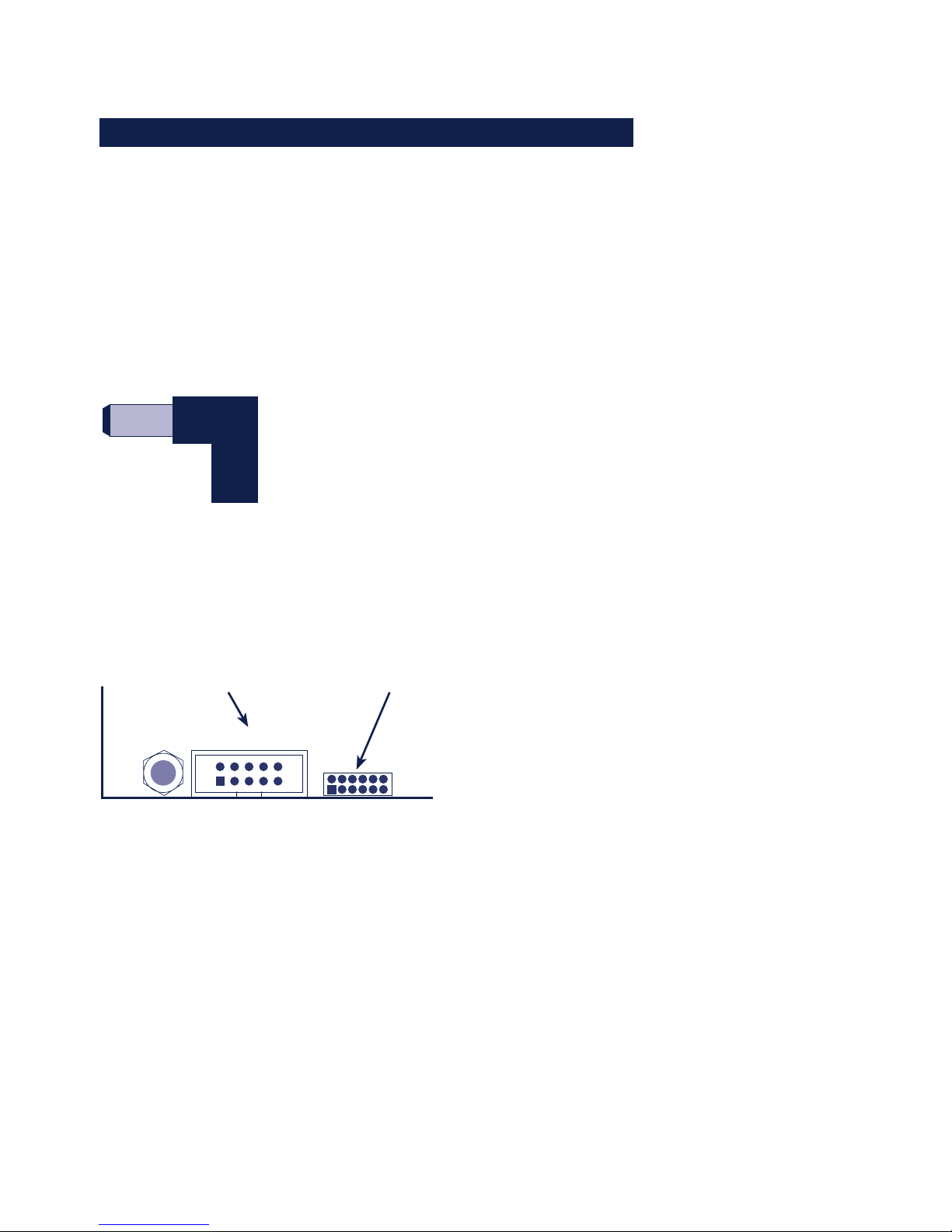
58231, 58431
The supply is brought in on a mains receptacle for hollow pin
plugs located in the edge of the board. The feed voltage must
be 5V ±5%.
Pin jack 5,5mm
Polarity: inner = GND
outer = +5V
58432
The supply voltage is brought in through one of the two post
connectors that are used for the serial signals as well. Supply
voltage has to be 5V +/-5%.
X1
Pin 1 = +5V
Pin 10 = GND
X4
Pin 1 = GND
Pin 12 = +5V
1
2
9
10
34567
8
16
712
The current draw is indicated in the technical appendix.
Page 45
45
W&T Supply voltage
Subject to error and alteration
4.6 Com-Server Highpeed 19“
• Models: 58331, 58334
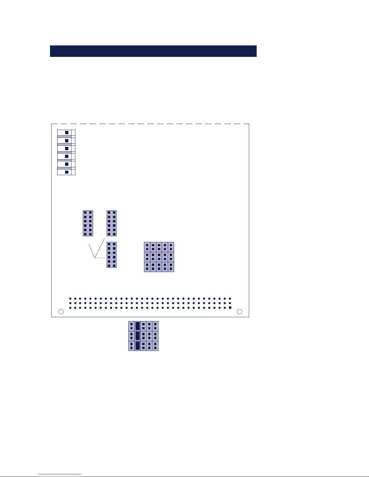
The Com-Server Highspeed 19" models get their supply voltage
through the 96-pin VG connector:
c
b
a
132
Component side of board
Slots for serial
ports
B
D
C
Row 1
Row 5
Jumper a
Jumper b
Jumper c
Jumper area
5V
5V
GND
GND
12V
Alternat supply voltage also
possible through the 6-pin
terminal strip, RM 3,96
Example for VME-Bus J2:
Row 1
Row 5
Jumper a
Jumper b
Jumper c
Use the following table to determine how jumpers a-c in the
corresponding row depending on which bus system is used.
Page 46

46
W&T Supply voltage
Jumper
Row 1
Row 2
Row 3
Row 4
Row 5
A
9c
2b
32c
32c
32c
B
32c
1b
31c
1c
29a
C
31c
n.c.
3c
13a
9a
Com-ServerPin VG strip
A
GND
GND
GND
GND
GND
B
+5V
+5V
+5V
+5V
+5V
C
+12V
+12V
+12V
+12V
+12V
Standard (all three jumpers of row closed)
VME-Bus J1
VME-Bus J2
Multibus II
ECB Bus
BUS7ISA
1
For standard operation of the Com-Server only the 5V
supply is needed. The 12V voltage is simply brought
through a fuse to Pin 11 on the module slots where it is used to
supply future interface modules.
Page 47

47
W&T
Subject to error and alteration
5 Interfaces and displays
. Ethernet interface
. Serial interfaces and options
. LED displays
Page 48
48
W&T Interfaces and displays
5.1 Ethernet connection
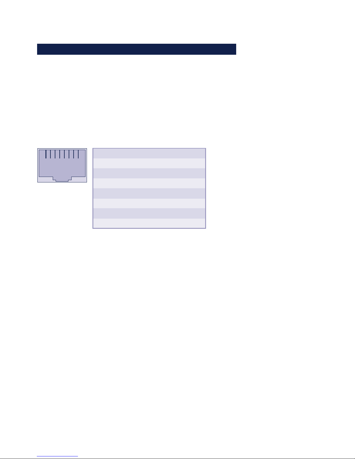
All Com-Server models incorporate an IEEE 802.3-compatible
network interface on a shielded RJ45 connector. The pin
assignments correspond to an MDI port, so that the
connection to the hub or switch is accomplished using a 1:1
shielded patch cable. The OEM model 58432 can also be
optionally equipped with an LSA-Plus no-strip connect
terminator module.
1 2 3 4 5 6 7 8
Pin
1
2
3
4
5
6
7
8
Direction
Out
Out
In
In
IN
In
In
In
Models
withpout PoE
Tx+
Tx-
Rx+
nc
nc
Rx-
nc
ncv
Models
with PoE
Tx+
Tx-
Rx+
Vcc positive
Vcc positive
Rx-
Vcc negative
Vcc negative
Power-over-Ethernet
The model 58641 Com-Server 58641 can obtain power as
defined in IEEE802.3af/Power-over-Ethernet. Either the data
pairs or the unused wire pairs in 10/100BaseT may be used
(see also the section Supply Voltage).
Auto Negotiation: 10/100BaseT, Full/Half Duplex
All Com-Servers are factory set to operate in Auto-Negotiation
mode on the network side. The data transmission speed and
duplex are automatically negotiated with the connected switch/
hub and set accordingly.
In addition to the Auto-Negotiation mode, both the Com-Servers as well as many switches can be configured for fixed
transmission parameters with respect to speed and duplex. To
prevent communications problems (duplex mismatch), only the
following two combinations are permissible:
Page 49

49
W&T Interfaces and displays
Subject to error and alteration
• Both parties (switch and Com-Server) are operated in Auto-
Negotiation mode.
• Both parties are configured for the same (fixed)
transmission speeds and duplex mode.
Activating/deactivating Auto-Negotiation
Use menu sequence Setup System r Link Speed to switch
between Auto-Negotiation and fixed transmission speeds/
duplex mode.
Galvanic isolation
The network connection is galvanically isolated with respect to
the supply voltage as well as the serial interface(s) for at least
500V
rms
.
Link-Status
The current link status is indicated by the Error LED on the
device front panel: Flashing at a rate of 1-2 seconds indicates
that there is no connection to the hub or that the connection is
faulted.
1
Managable switches often have special protocols
(spanning tree, port trunking, ...) as required for
example for uplinks to other switches or broad-band connection
of servers. These protocols are not generally required for
connecting a normal terminal device such as the Com-Server,
and they do under some circumstances significantly delay
opening of communication after a new start. We recommend
deactivating these protocols and functions on the port used for
the Com-Server. Please consult here with the responsible
network administrator.
Page 50

50
W&T Interfaces and displays
5.2 RS232/422/485 combi-module
Com-Server models 58631, 58633, 58031, 58034, 58331,
58334 and 58231 come standard with an RS232/422/485
multi-port whose modes are described below.
The ports on the Com-Server 58633 are also galvanically
isolated from each other and with respect to the supply
voltage with a dielectric strength of 1kV.
All external signal lines use ESD-immune interface
components to provide protection against static discharges
of up to 15kV per IEC 801-2, Level 4.
The OEM models 58431 and 58432, which are intended for
integration into existing systems, are equipped with a serial
TTL interface (= UART interface).
5.2.1 Opening the Com-Server
To open the Com-Server, plug the DB9 connector into the
serial port. After tightening the two mounting screws, pull on
the DB9 plug to remove the circuit board from the housing..
The office versions can be opened by removing the four
upper screws on the enclosure sides.
In the case of the compact version 58231, the bump guard on
the housing side with the serial port must first be removed. This
reveals four screws, which are removed in order to remove the
circuit board from the housing.
i
Equipping Com-Servers
with interface modules
other than those
already installed
is a modification which
must be performed
only by W&T.
Page 51

51
W&T Interfaces and displays
Subject to error and alteration
5.2.2 Mode selection
Switching between the modes is accomplished using the
internal DIL switches located on the respective interface
module. The following table shows an overview of all modes:
SW5
OFF
ON
ON
ON
Mode
RS232
(1)
RS422, RS485
4-wire bus master
RS485 4-wire
automatic control
RS485 2-wire
automatic control
SW1
OFF
OFF
OFF
ON
SW2
OFF
OFF
ON
ON
SW3
OFF
OFF
OFF
OFF
SW6
OFF
x
x
x
SW7
OFF
x
x
x
SW8
ON
OFF
OFF
OFF
SW4
OFF
OFF
OFF
OFF
(1) Factory default
5.2.3 RS232 mode (factory default)
The pin configuration of the RS232 port is identical to that of a
PC, which allows you to use standard cables. Be sure that the
Com-Server port and that on the serial terminal device are
configured for the identical transmission parameters and
handshake procedure.
DIP switch setting
SW5
OFF
Mode
RS232
SW1
OFF
SW2
OFF
SW3
OFF
SW6
OFF
SW7
OFF
SW8
ON
SW4
OFF
1
The terminating DIL switches SW6 and SW7 must never
be in the ON position when using the module in RS232
mode. This will result in a significant increase in the current
draw and may cause the RS232 driver to fail.
Page 52

52
W&T Interfaces and displays
Pin assignment and function RS232, DB9
Pin
1
2
3
4
5
6
7
8
9
Direction
(IN)
IN
OUT
OUT
---
IN
OUT
IN
(IN)
Signal
NC/DCD
RxD
TxD
DTR
GND
DSR
RTS
CTS
NC/RI
Description
Data carrier
detect
Receive Data
Transmit Data
Data Terminal
Ready
Signal Ground
Data Set Ready
Ready To Send
Clear To Send
Ring indicator
Default Funktion (1)
1-port models: Not connected
4-port models: Ignored
Data in
Data out
12V for existing TCP
connection to a client or server
---
ignored
Handshake output
+12V = ready to receive data
- 12V = not ready to receive data
Send data only at +3...12V
1-port models: Not connected
4-port models: Ignored
(1) Applies only to the hardware handshake setting
Wiring examples
Com-Server <> PC, 25-pin
W&T Art. No. 1179x
1
2
3
4
5
6
7
8
20
2
3
6
7
8
5
4
DB25/female
DB9/female
Com-Server <> PC, 9-pin
W&T Art. No. 1199x
1
2
3
4
5
6
7
8
4
3
2
1
5
6
8
7
DB9/female
DB9/female
Com-Server -> printer
W&T Art. No. 1189x
2
3
4
5
6
8
2
3
5
6
7
20
DB25/male
DB9/female
Com-Server <> modem
W&T Art. No. 1198x
1
2
3
4
5
6
7
8
9
8
3
2
20
7
6
4
5
22
DB25/male
DB9/female
Page 53

53
W&T Interfaces and displays
Subject to error and alteration
5.2.4 RS422/485 mode
As opposed to RS232, an RS422 interface allows transmission
distances of up to 1000 meters. The RS485 mode allows you to
integrate corresponding 2- or 4-wire bus sytems into a TCP/IP
network with the help of the Com-Server.
1
Especially when using longer cable lengths in
industrial environments, potential differences need to
be taken into consideration. To prevent any resulting
transmission problems or hardware damage, recommended
use of the Com-Server Highspeed Isolated 58633, which has
three galvanically isolated serial ports. Alternately the
galvanic isolation can be achieved by means of an external
isolator (e.g. W&T RS422/485-Isolator Model 66201).
DIP switch setting
SW5
ON
ON
ON
Mode
RS422, RS485
4-wire bus master
RS485 4-wire
automatic control
RS485 2-wire
automatic control
SW1
OFF
OFF
ON
SW2
OFF
ON
ON
SW3
OFF
OFF
OFF
SW6
x
x
x
SW7
x
x
x
SW8
OFF
OFF
OFF
SW4
OFF
OFF
OFF
Pin assignment and function RS422/485, DB9
Pin
1
2
3
4
5
6
7
8
9
Direction
OUT
IN
OUT
IN
---
OUT
IN
OUT
IN
Signal
TxD A/-
RxD A/-
RTS A/-
CTS A/-
GND
TxD B/+
RxD B/+
RTS B/+
CTS B/+
Description
Transmit Data A
Receive Data A
Ready To Send A
Clear To Send A
Signal Ground
Transmit Data B
Receive Data B
Ready To Send B
Clear To Send B
Default function (1)
Data output
Data input
Handshake output
Handshake input
---
Data output
Data input
Handshake output
Handshake input
(1) with factory default setting
Page 54

54
W&T Interfaces and displays
Modes
The DIL switches are used to set the following modes:
• RS422, RS485 4-wire bus master
Provides one data and handshake channel each in each
direction. The RS422/485 drivers and receivers are
always active in this mode.
• RS485 4-wire with automatic control
One data channel is available in each direction. The
RS485 driver chip is automatically activated each time
data is sent out and then disabled when data is finished
sending. The receive channel is always active in this
mode.
• RS485 2-wire bus with automatic control
One data channel is available in each direction. The
RS485 driver chip is automatically activated each time
data is sent out and then disabled when data is finished
sending. The receive channel is deactivated when the
driver is on, and on when the driver is disabled.
Handshake for RS485 modes
RS485 bus systems do not use flow control in the traditional
sense for data integrity, but rather a logical protocol. The
handshake procedure for the Com-Server must therefore be
set to NO (see The serial parameters (Menu: UART Setup).
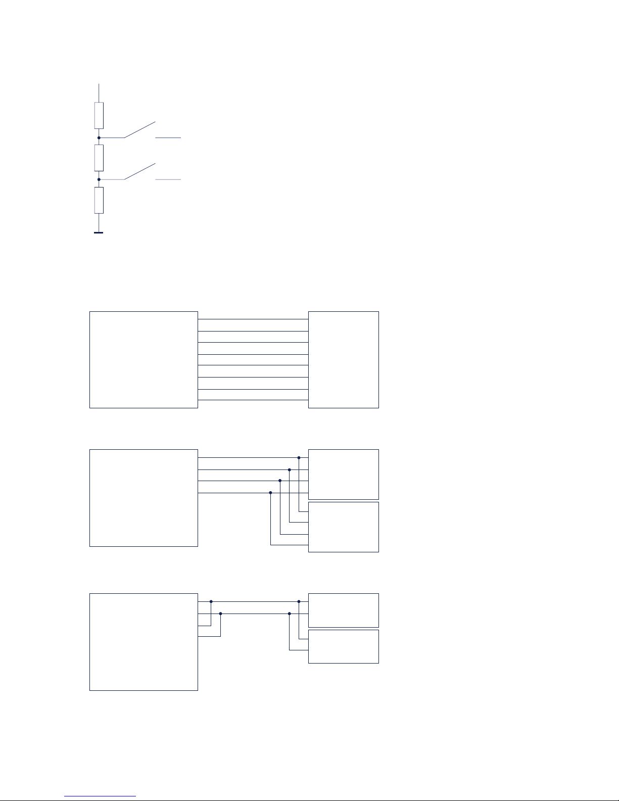
Terminating
All RS485 modes require a termination network on the bus
ssytem which ensures a defined rest state in the high-ohmic
phases of bus operation. Connection of the bus system with
a termination network can be done in the interface by closing
the DIP switches 6 and 7 on the module:
Page 55
55
W&T Interfaces and displays
Subject to error and alteration
330O 330O120O
+5V
SW6
SW7
Data In B
Data In A
Wiring examples
RS422 connection with hardware handshake
Com-Server
RS422/485
Data Out A
Data Out B
Data In A
Data In B
Handshake Out A
Handshake Out B
Handshake In A
Handshake In B
RxD A (-)
RxD B (+)
TxD A (-)
TxD B (+)
CTS A (-)
CTS B (+)
RTS A (-)
RTS B (+)
1
6
2
7
3
8
4
9
RS422
device
RS485 connection (4-wire bus master)
Com-Server
RS422/485
Data Out A
Data Out B
Data In A
Data In B
Handshake Out A
Handshake Out B
Handshake In A
Handshake In B
1
6
2
7
3
8
4
9
RxD A (-)
RxD B (+)
TxD A (-)
TxD B (+)
RS485
device
RxD A (-)
RxD B (+)
TxD A (-)
TxD B (+)
RS485
device
RS485 connection 2-wire
Com-Server
RS422/485
Data Out A
Data Out B
Data In A
Data In B
Handshake Out A
Handshake Out B
Handshake In A
Handshake In B
1
6
2
7
3
8
4
9
Bus A (-)
Bus B (+)
RS485
device
Bus A (-)
Bus B (+)
RS485
device
Page 56
56
W&T Interfaces and displays
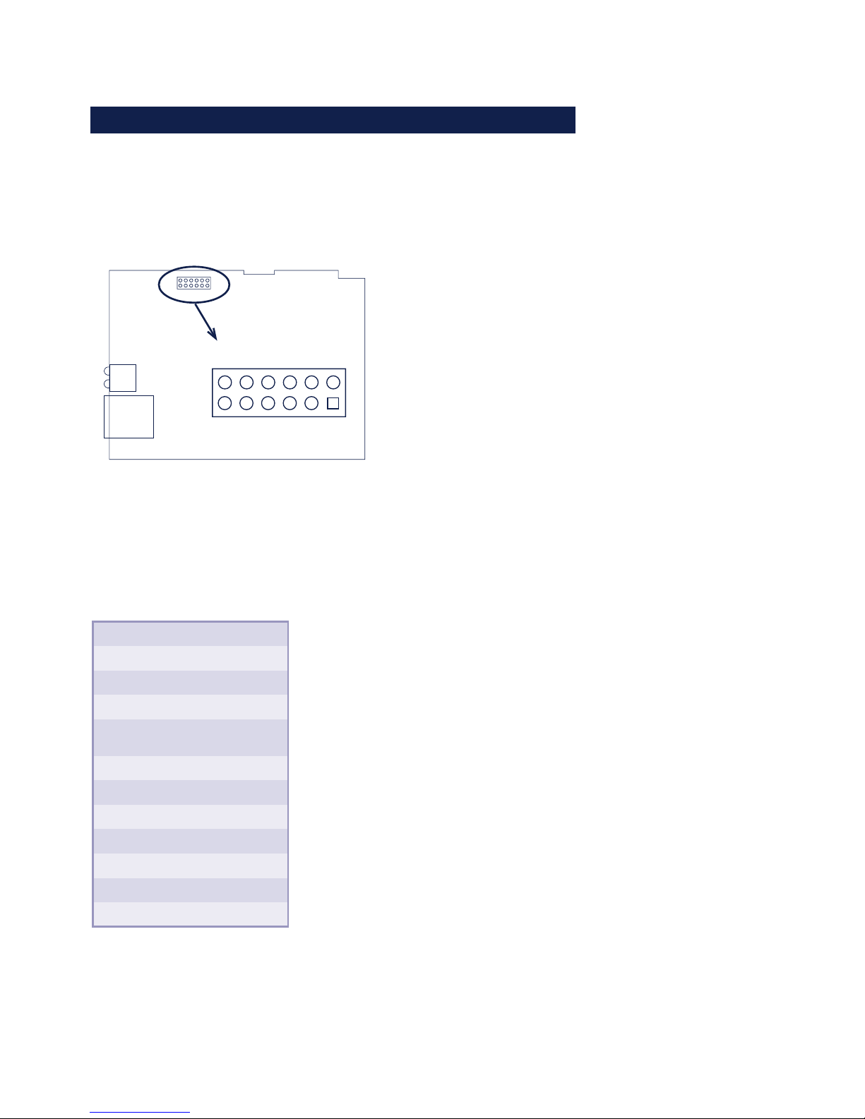
5.3 Interface for the OEM-Com-Server 58431
The OEM model 58431 has a UART interface that operates at
TTL levels, which is implemented on a 2mm square post
header. As an option, interface modules for RS232, RS422/
485 or the multi-port can be connected.
RJ45
LEDs
1
6
7
12
1
Wiring assignment for the OEM model 58432 „credit
card format“ differ from those described here. For this
model please consult the belonging special section
Pin assignment and function TTL interface 58431
Pin
1
2
3
4
5
6
7
8
9
10
11
12
Signal
5V
NC
RxD
TxD
Reset (1)
CTS
DTR
DSR
RTS
NC
NC
GND
Function
Vcc
---
Data in
Data out
Reset
in-/output
Input
Output
Input
Output
---
---
Signal ground
(1)
The open collector feature of the reset pin allows function as
a LOW-active in- and output. A reset triggered for example by
the watchdog in the Com Server can be used here for your own
Page 57

57
W&T Interfaces and displays
Subject to error and alteration
purposes. Applying a GND level for at least 100ms (using a
button for example) forces a restart of the Com Server.
Page 58

58
W&T Interfaces and displays
5.4 Option: 20mA interface
All Com-Servers in the Highspeed series with the exception of
model 58633 can be equipped optionally with 20mA interfaces
instead of the RS232/422/485 combi-module.
The interface can be used as an active or passive 20mA
component. In the active mode the interface supplies the
current required by the respective 20mA loop, while in the passive mode the loop current must be supplied by the connected
device.
Pin assignment and function 20mA, DB9
Pin
1
2
3
4
5
6
7
8
9
Signal
Data Out 20mA
Data Out +
Data Out -
Data Out GND
n.c.
Data In 20mA
Data In +
Data In -
Data In GND
Function
Current Out +20mA
Output
Output
Current Out Ground
--
Current In +20mA
Input
Input
Current In Ground
The operating mode can be selected for both loops seperately.
Examples of interface switching into active/ passive mode are
shown on the following drawings:
Page 59

59
W&T Interfaces and displays
Subject to error and alteration
Com-Server Tx and Rx loop active
RxD +
RxD -
TxD +
TxD -
Passive 20mA-
device
Com-Server Tx and Rx loop passive
Com-Server Tx loop active, Rx loop passive
Com-Server
20mA
Data Out 20mA
Data Out +
Data In -
Data Out GND
Data In 20mA
Data In +
Data In -
Data In GND
1
2
3
4
6
7
8
9
Com-Server
20mA
Data Out 20mA
Data Out +
Data In -
Data Out GND
Data In 20mA
Data In +
Data In -
Data In GND
1
2
3
4
6
7
8
9
RxD +
RxD -
TxD +
TxD -
Active 20mA-
device
RxD +
RxD -
TxD +
TxD -
Avtive/passive
20mA device
Com-Server
20mA
Data Out 20mA
Data Out +
Data In -
Data Out GND
Data In 20mA
Data In +
Data In -
Data In GND
1
2
3
4
6
7
8
9
Page 60
60
W&T Interfaces and displays
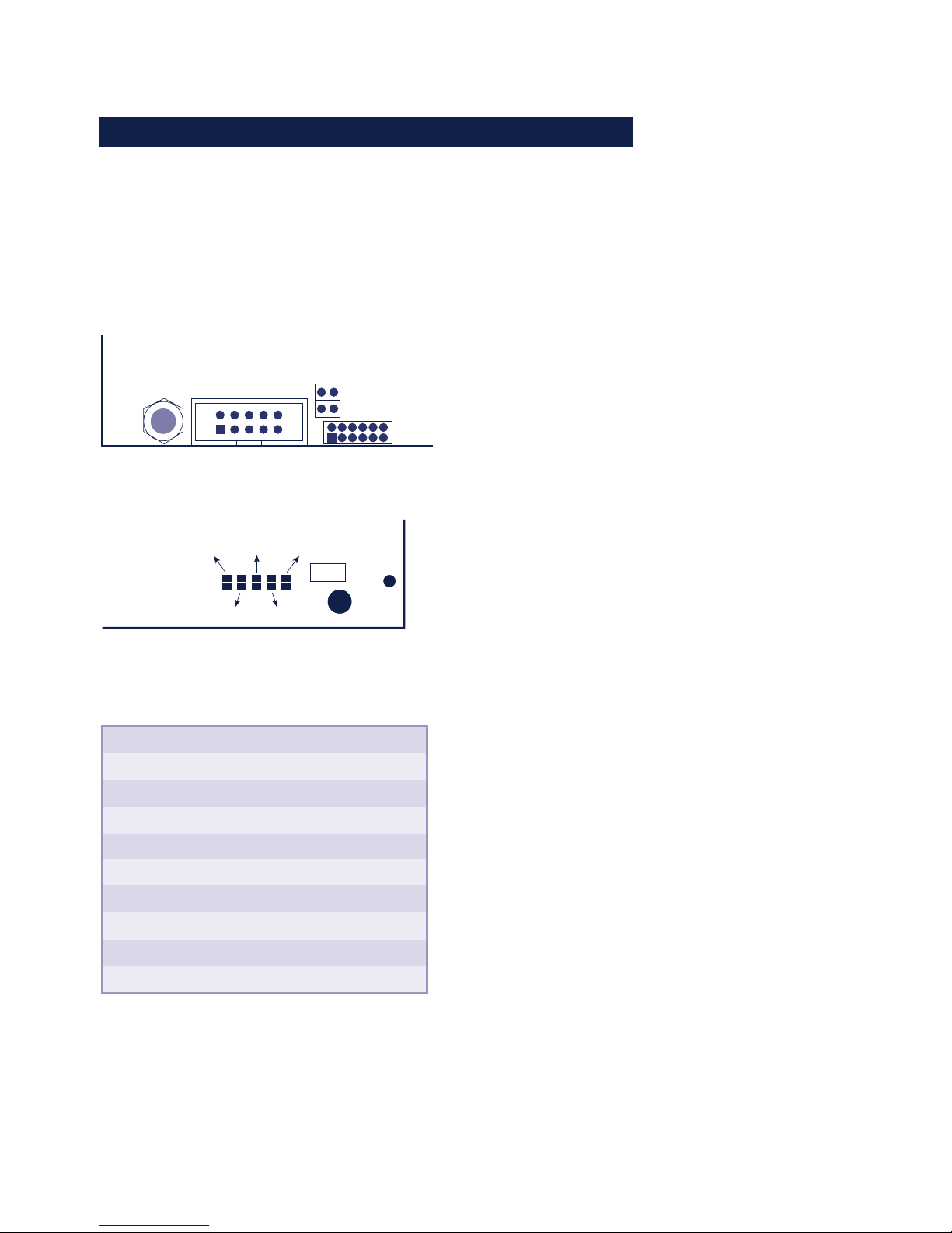
5.5 Interfaces for the OEM-Com-Server 58432
The OEM model 58432 in credit card format has in addition to
an RS232 interface with TTL levels an onboard RS485 interface.
Both interfaces are located on the 10-pin connector X1 with the
locking collar. Reconfigure using the solder jumpers on the
underside of the board.
PCB bottom side
Fuse
LB8
LB5
LB7
LB6
LB9
PCB top side
X1
J3
J4
RS485
termination
ON/OFF
1
2
9
10
34567
8
16
712
Pin assignment X1
Pin
1
2
3
4
5
6
7
8
9
10
Signal
+5V/+24V
RxD
TxD
RES/ (1)
CTS
DTR
DSR/A
RTS/B
GND 24V
GND 5V
Function
RS232/TTL
Supply
Input
Output
In-/Output
Input
Output
Input
Output
Supply
Supply
Function
RS485
Supply
(RxD)
(TxD)
(In-/Output)
(Input)
(Output)
Bus A/-
Bus B/+
Supply
Supply
(1)
The open collector feature of the reset pin allows function as
a LOW-active in- and output. A reset triggered for example by
the watchdog in the Com Server can be used here for your own
purposes. Applying a GND level for at least 100ms (using a
button for example) forces a restart of the Com Server.
Preliminary
Page 61

61
W&T Interfaces and displays
Subject to error and alteration
The serial TTL interface
This interface can be configured as the TTL port of a UART.
The solder jumpers must be set as follows:
• LB5, LB6 = in
• LB7, LB8, LB9 = out
The RS485 interface with automatic control
The following configuration of solder jumpers establishes a
2-wire RS485 bus connection on pins 7 and 8 of X4.
• LB5, LB6 = out
• LB7, LB8, LB9 = in
The RS485 driver ship is automatically enabled each time
data is sent and disabled (high impedance state) again when
data output is finished. The RS485 receiving channel is
deactivated when the driver is on, but is switched on when
the driver is in the high impedance state.
RS485 mode requires that the bus system be terminated with a
termination network which ensures a defined idle state in the
high impedance phases of bus mode. If the bus system in
question does not already have a termination, one can be set
using (inserting) jumpers J3 and J4.
1
The serial TTL interface and the RS485 bus can be
used only in alternation.
Preliminary
Page 62
62
W&T Interfaces and displays
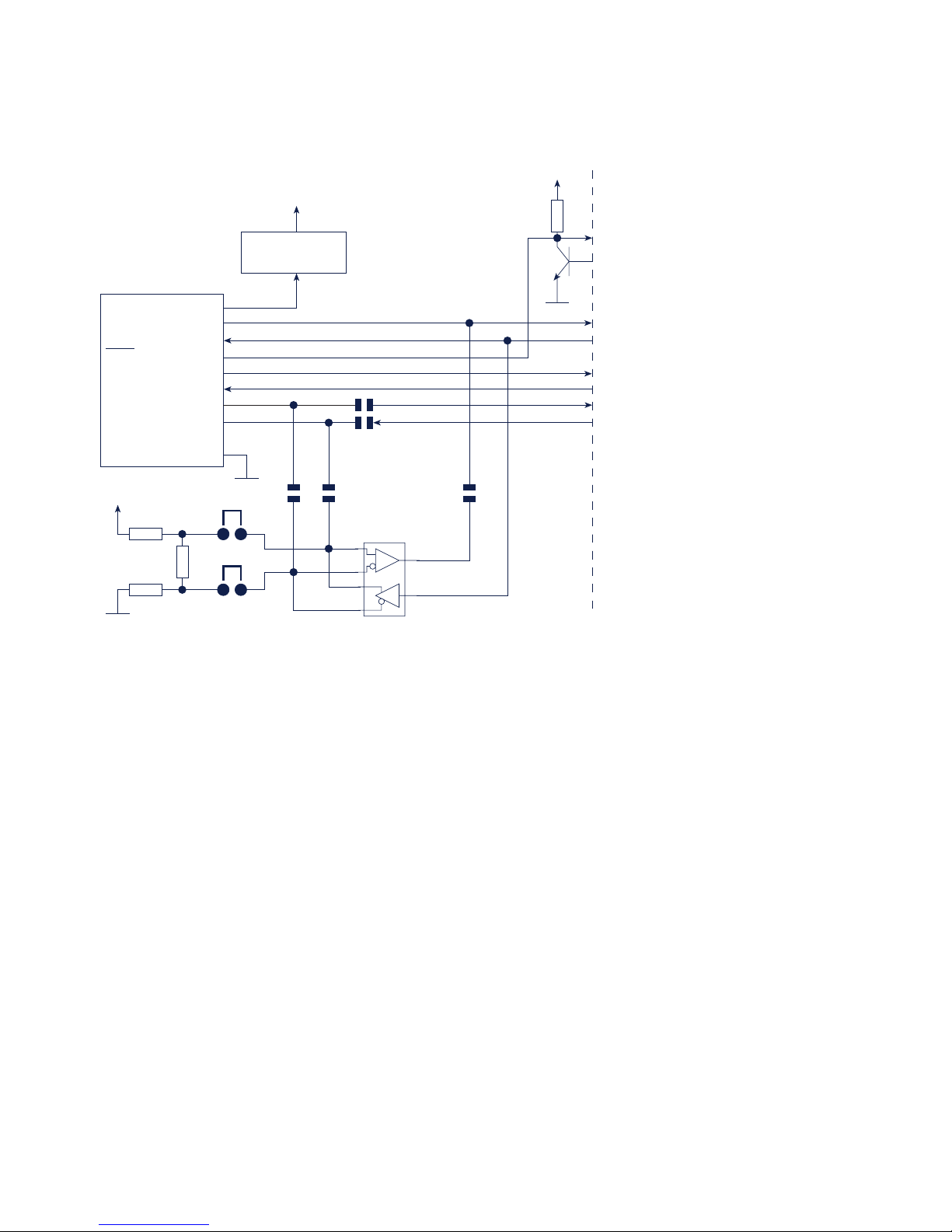
Basic diagram of the serial interfaces
1
2
3
4
5
6
7
8
9
10
+5V/+24V
RxD
TxD
RES
CTS
DTR
DSR / A
RTS / B
GND 24V
GND 5V
X1
RM2,54mm
Com-Server UART
Protective
circuit
Vcc
(internal)
RS485
Transceiver
LB5
LB6
LB7 LB8 LB9
330 Ohm
120 Ohm
330 Ohm
J4
J3
Vcc/5V
4,7 kOhm
Vcc/5V
Preliminary
Page 63

63
W&T Interfaces and displays
Subject to error and alteration
5.5 LED displays
• Power LED
Indicates supply voltage present. If the LED is not on,
check for correct wiring of the power supply.
• Status LED
Flashes whenever there is activity on the serial port.
Periodic flashing indicates that the port has a valid
connection to another network station. The status of the
serial port can also be read out using the Com-Server‘s
Telnet configuration tool.
• Error LED
The Error LED uses various flashing patterns to indicate
error conditions on the device or serial port. The error
texts for the previous five serial faults and the associated
system time (time between the last restart of the Com-Server and when the error occured) can also be read out
using the Telnet configuration tool.
1 xflashing = Check network connection
The Com-Server cannot receive a link pulse from a hub.
Check the cable or the hub port.
2 x flashing= Check serial data format
The serial port received at least one character with a
parity or framing error (= parity error / framing error), or
the data register of the serial receiver ship was written
even though the previous character was not read out.
Check the correctness of the serial parameters, the
handshake procedure and the connection cable.
3 x flashing = Check serial handshake
The serial connected device is not responding to the
handshake stop signal set by the Com-Server and
continues to send data. The result can be that the serial ring
memory is overwritten and data are lost. Check the handshake configuration of the device as well as the wiring of the
connection cable.
Page 64

64
W&T Interfaces and displays
All LEDs on = Self-test error
The self-test performed after each start or reset of the ComServer could not be correctly finished. This error can occur
when you have prematurely broken off a software update
and the full operating sofstware could not be transferred.
The Com-Server is no longer capable of being operated in
this condition. Repeat the software update over the network
(see „Firmware update of the Com-Server“), and address the
Com-Server using its assigned IP address. If this does not
eliminate the error or should the error occur irrespective of
any prior software update, please return the unit to W&T for
service.
Page 65

65
W&T
Subject to error and alteration
6 Configuration access to the Com-Server
After completing the hardware installation and assigning the IP address,
the remaining Com-Server configuration takes place over the network.
Here either a Telnet client or, after it has been activated, an Internet
browser can be used.
. Telnet configuration under Windows
. Configuration with the Internet browser
Page 66

66
W&T Configuration access to the Com-Server
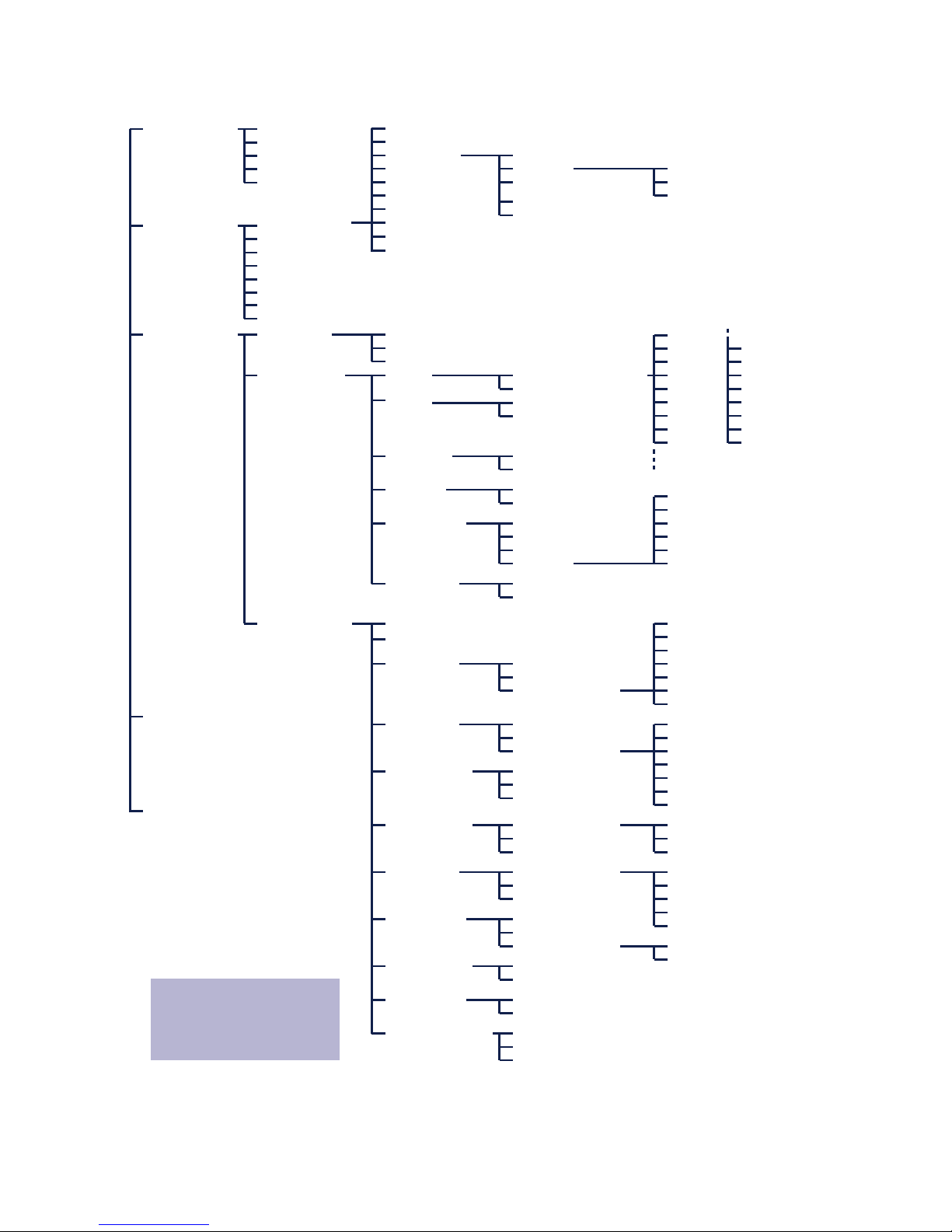
6.1 Configuration menu structure
The setup of the Com-Server is treelike regardless of whether
the configuration is used for a Telnet client or an Internet
browser. An overview of all the levels can be found in the
following illustration.
Prior to configuration a valid IP address must have been already
assigned to the Com-Server (see “Assigning the IP Address”).
Access is then possible from virtually any computer having
network access and an installed TCP/IP protocol.
A detailed description of both configuration access types, their
conditions as well as the respective navigation within the menu
tree can be found in the following section.
1
HTTP protocol and its standard port 80 are frequent
targets of Web attacks. In order not to impair data
throughput of the applications and of the Com-Server, Web
Based Management is therefore factory disabled. Ways of
activating this as part of the startup process can be found in
the section on Web Based Management.
i
If you exit the
configuration menu by
closing the Telnet
connection without first
invoking SAVE Setup,
the original
configuration is
retained.
Page 67
67
W&T Configuration access to the Com-Server
Subject to error and alteration
SETUP System Setup TCP/IP
Telnet Password
System Password
System Name
Flash Update
Factory Defaults
Reset
Link Speed (Auto, 10/100BT, HD/FD)
SETUP Port 0
SETUP Port 1
SETUP Port 2
SETUP Port 3
SAVE Setup
TCP Client
UDP Client
Serial Socket
Interface
Telnet Client
FTP Client
Box to Box
(TCP)
IP Bus Mode
SLIP Router
System Options
Server Port
Server IP/URL
Special Options
Port State
UART Setup
TCP/IP Mode
Connection State
Error State
Clear Port Mode
Baud
Parity
Data Bits
Stopbit
Handshake
FIFO S/R:
Standard Baudrates
Special Baud Divisor
230,4k
172,8k
115,2k
57600
38400
19200
9600
4800
2400
1200
600
300
150
110
757200
50
NONE
EVEN
ODD
8
7
None
Hardware
Software
Special
1
2
Pin: RTS
Pin: DTR
Pin: CTS
Pin: DSR
XON/XOFF
XON/XOFF (Filter)
FIFOs OFF
FIFOs ON
disable
8/8
16/16
32/56
56/60
Local Port TCP/UDP Inactivity Timeout
Connect. Timeout
Disconnect Char
Dispatch String 1
Dispatch String 2
Client: "C"+Addr
Response Mode
Server Port
Server IP/URL
Special Options
Serial Coding
Serial Protocol
Dispatch String 1
Dispatch String 2
Client: "C"+Addr
Disconnect Char
Write: "C"+Addr
Serial Protocol
Serial Coding
Protocol Char
Server Port
Server IP/URL
Special Options
Disconnect Char
Inactivity Timeout
Serial 0d -> 0d00
Server Port (21)
Server IP
Special Options
Auto FTP
FTP Client Login
Inactivity Timeout
Connect. Timeout
Protocol Char
Server Port
Server IP/URL
Special Options
Server Port (21)
Server IP
Special Options
Dispatch String 1
Dispatch String 2
Slave: Master IP
Master: Subnet IP
Net Address
SLIP-Net Routing
Network Delay
Flush Buffer
Telnet Echo
(Highspeed
Serial)
Logout
Retransm. Timeouts
INFO System Cable Type
MAC address
SOFTW Date/REV
HARDW Rev
Run Time
IP-Address
Subnet Mask
Gateway
MTU (560-1460)
BOOTP Client
Keep Alive Time
Standard Gateway
Route 1
Route 2
Route 3
Route 4
Destination
Netmask
Gateway
WBM Port
DNS Server
DHCP Client
Control Port TCP
Telnet:
Transfer the selected parameters
and save all settings
in non-volatile memory on the ComServer
Browser:
Transfer the selected parameters
and save all settings
in non-volatile memory on the ComServer
To activate the new settings
always save using SAVE Setup
with Telnet or the LOGOUT
link on the webpages
Page 68
68
W&T Configuration access to the Com-Server
6.2 Configuration via Telnet
A Telnet client comes standard with nearly all operating
systems that support TCP/IP protocol. Under Windows 9x/
NT/2000/XP this is normally found in the Windows system
directory.
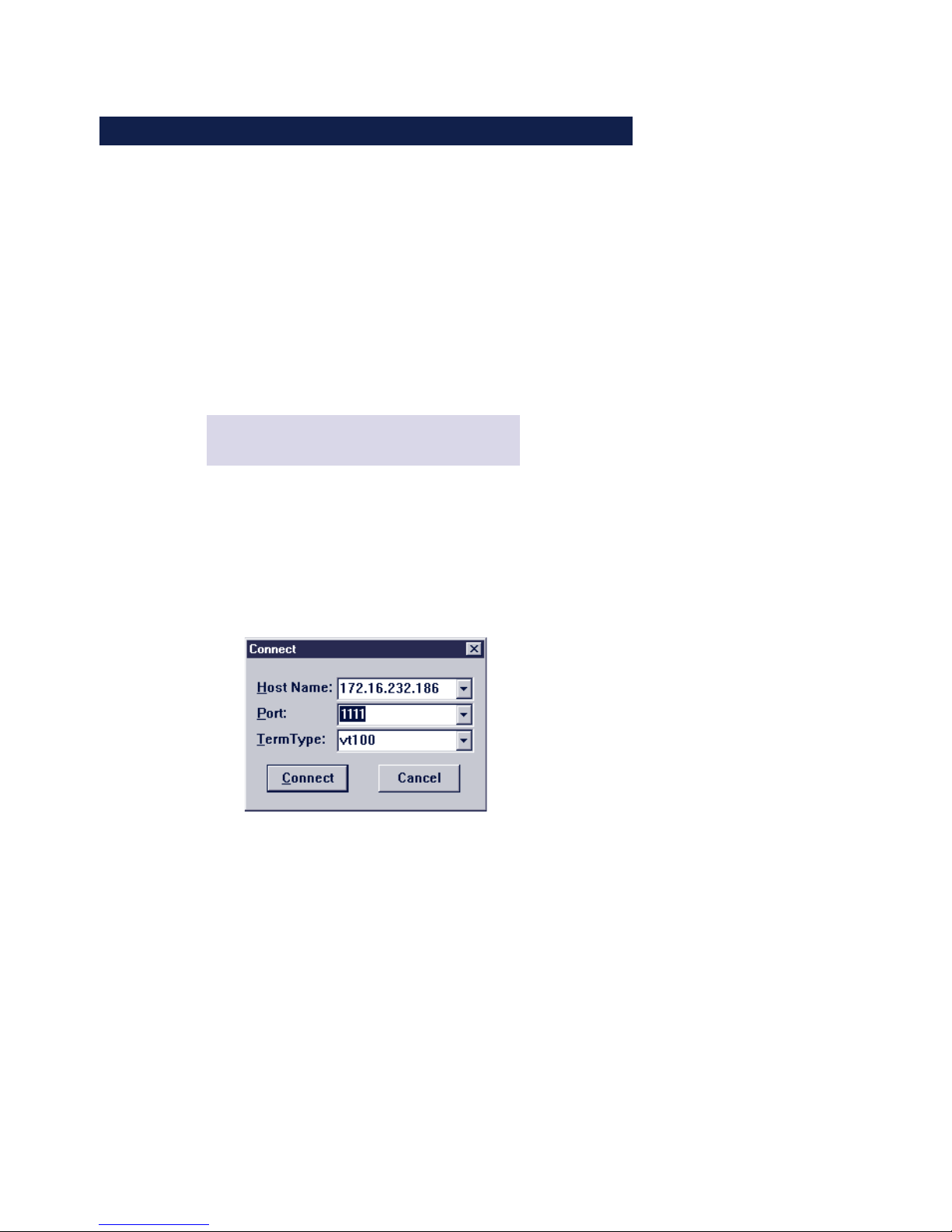
The configuration menu for the Com-Server is reached
through TCP port 1111. You must therefore start the
connection from within the Telnet client using the
corresponding parameters:
Telnet [IP address] 1111
[adress] = IP address of the Com-Server
1111 = Configuration port of the Com-Server
Under Windows 9x/NT you only need to use Start r Run
telnet. Then in the submenu Network system... of the
Connect menu enter as the host name the IP address of the
Com-Server and as the connection port number 1111.
If the connection could be opened and no system password
is assigned (= factory default setting), you will see the
following menu in your Telnet window. If a system password
was configured, this will be asked for in front of the menu.
Page 69

69
W&T Configuration access to the Com-Server
Subject to error and alteration
***************************
* Com-Server Highspeed *
* COMSERVER-0A1B2C *
***************************
1. INFO System
2. SETUP System
3. SETUP Port 0 (High-Speed Serial)
4. SETUP Port 1 (High-Speed Serial)
5. SETUP Port 2 (High-Speed Serial)
6. SETUP Port 3 (High-Speed Serial)
7. SAVE Setup
INFO System, SETUP System and SAVE Setup as well as their
sub-menus are the same for all Com-Server models and are
described in the following section Basic Configuration of the
Com-Server.
The menu items SETUP Port x are dependent of the number of
serial ports on the respective Com-Server. For example, all
single-port versions will only provide the SETUP Port 0 menu.
The description of these branches can be found in the section
Configuration of the Serial Ports.
6.2.1 Navigation within the Telnet menu
An overview of the entire Com-Server configuration menu is
shown on the previous page. On the monitor you will see
always just one level of the selected menu. Simply entering
the number of the desired menu and pressing the ENTER key
takes you to the next level. Entering a q or pressing the
ENTER key takes you back to the previous menu level.
Page 70

70
W&T Configuration access to the Com-Server
The last configured value of a menu item appears in
parentheses. If you make changes, the new value will appear at
this point the next time the menu is opened. It only becomes
effective in the Com-Server itself however if you have saved it
using SAVE Setup.
As long as you do not open this menu item, you can move
around in the entire menu and change values without
actually changing anything.
i
If you exit the
configuration menu by
closing the Telnet
connection without
first doing a SAVE Set-
up, the original
configuration will be
retained.
Page 71

71
W&T Configuration access to the Com-Server
Subject to error and alteration
6.3 Configuration via Browser - Web Based Management
The Com-Server also allows configuration via HTTP protocol
and a standard Internet browser. The menu structure of the
WBM (Web Based Management) is compatible with the Telnet
configuration.
For reasons of security and downward compatibility, WBM is
factory disabled.
6.3.1 Activating WBM with the WuTility-Tool
The Web-Based-Management of the Com-Server can be activated
at any time using WuTility as part of assigning the network
parameters. Select the Com-Server in the device list and then
click on the IP address button. In the first window of the dialog
enter the desired values for IP address, subnet mask and
gateway and then click on the Continue button. In the following
window activate the WBM option and enter the desired TCP port
number. As a rule HTTP standard port 80 should be used. If
use of port 80 is not possible or desired, then the deviating
port number must be explicitly specified in the address line of
the browser when opening the Com-Server homepage:
http://[IP address or Hostname]:[Port number]
6.3.2 Activating WBM via the serial interface
When serially assigning the IP number, you can optionally
specify the TCP port number under which the WBM should
be accessible. To do this, first connect the serial port A on
the Com-Server and the COM port on your computer using a
null modem cable. Start a terminal program and set the
transmission parameters to 9600 baud, 8 data bits, no parity
Page 72

72
W&T Configuration access to the Com-Server
and no handshake. During a reset of the Com-Server hold the x
key down until after approx. 2 sec. the IPno.+<Enter>: prompt
appears. Now directly following the IP address enter the
extended address string +w[Portno.]. Portno. represents here
the desired TCP port in decimal format. A value of 0 deactivates
the WBM.
After finishing your entry by pressing the Return key, the values
are stored in the non-volatile memory and you can immediately
access the Com-Server and the set WBM port using your Internet
browser.
1
Additional information about serial configuration
possibilities for the Com-Server and navigation within the
WBM can be found in the sections Serial Assignment of the IP
Address, Subnet Mask and Gateway, and Navigation within the
WBM.
Example 1:
Here the IP address 172.17.231.99 is assigned to the ComServer and +w80 is used to activate the WBM on the HTTP
standard port.
xxx -> Com-Server
IP no.+<ENTER>: <- Com-Server
172.17.231.99+w80 -> Com-Server
172.17.231.99-1 <- Com-Server
Example 2:
In this example the Com-Server gets address 172.17.231.99,
Subnet-Mask 255.255.0.0 and the Gateway 172.17.231.52.
In addition, -0 is entered to turn off BOOTP/DHCP protocol and
+w8585 to activate WBM on TCP port 8585.
xxx - > Com-Server
IP no.+<ENTER>: <- Com-Server
172.17.231.99,255.255.0.0,172.17.231.52-0+w8080 -> Com-Server
172.17.231.99,255.255.0.0,172.17.231.52-0+w8080 <- Com-Server
Page 73
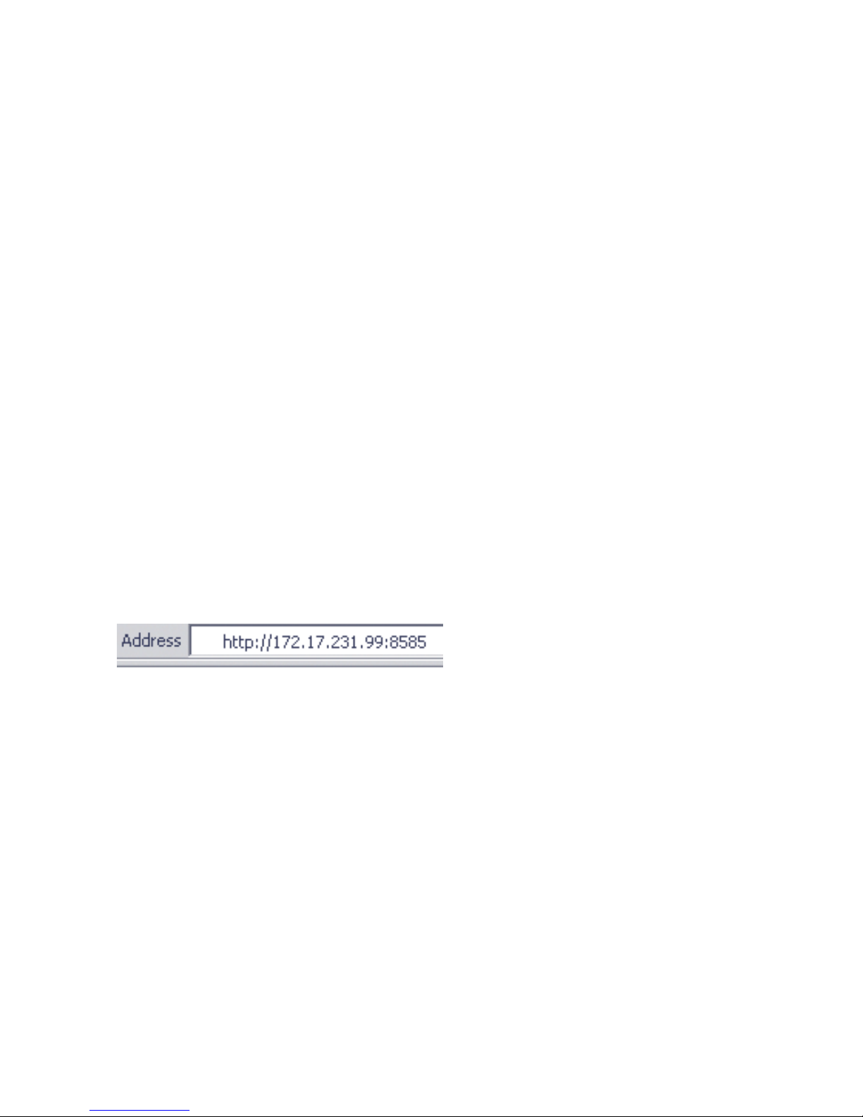
73
W&T Configuration access to the Com-Server
Subject to error and alteration
6.3.3 Activating WBM from the configuration menu
If you want to activate WBM on an already operational Com-Server, you can do this via Telnet configuration. Start a Telnet
session on port 1111 of the Com-Server. In the menu branch
2. SETUP System r 1. Setup TCP/IP r 6. WBM Port
enter the decimal number of the desired TCP port under which
you want to reach the WBM. Then press the Return key until you
are back in the main menu and from there open the SAVE Setup
item. After you have quit the Telnet session, you can now
access the Com-Server using an Internet browser.
6.3.3 Starting and navigating the WBM
To access the Web pages after activating the WBM, start your
Internet browser and enter the IP address of the Com-Server
and the configured port number in the address line:
http://[IP address]:[Portnumber]
If the HTTP standard port 80 was configured for WBM, you do
not need to explicitly indicate the port number in the address
line.
You will now be given the start page of the Com-Server with the
system password prompt. The factory default setting is for no
system password, so that you can get to the configuration
menu by simply actuating the login button.
Page 74
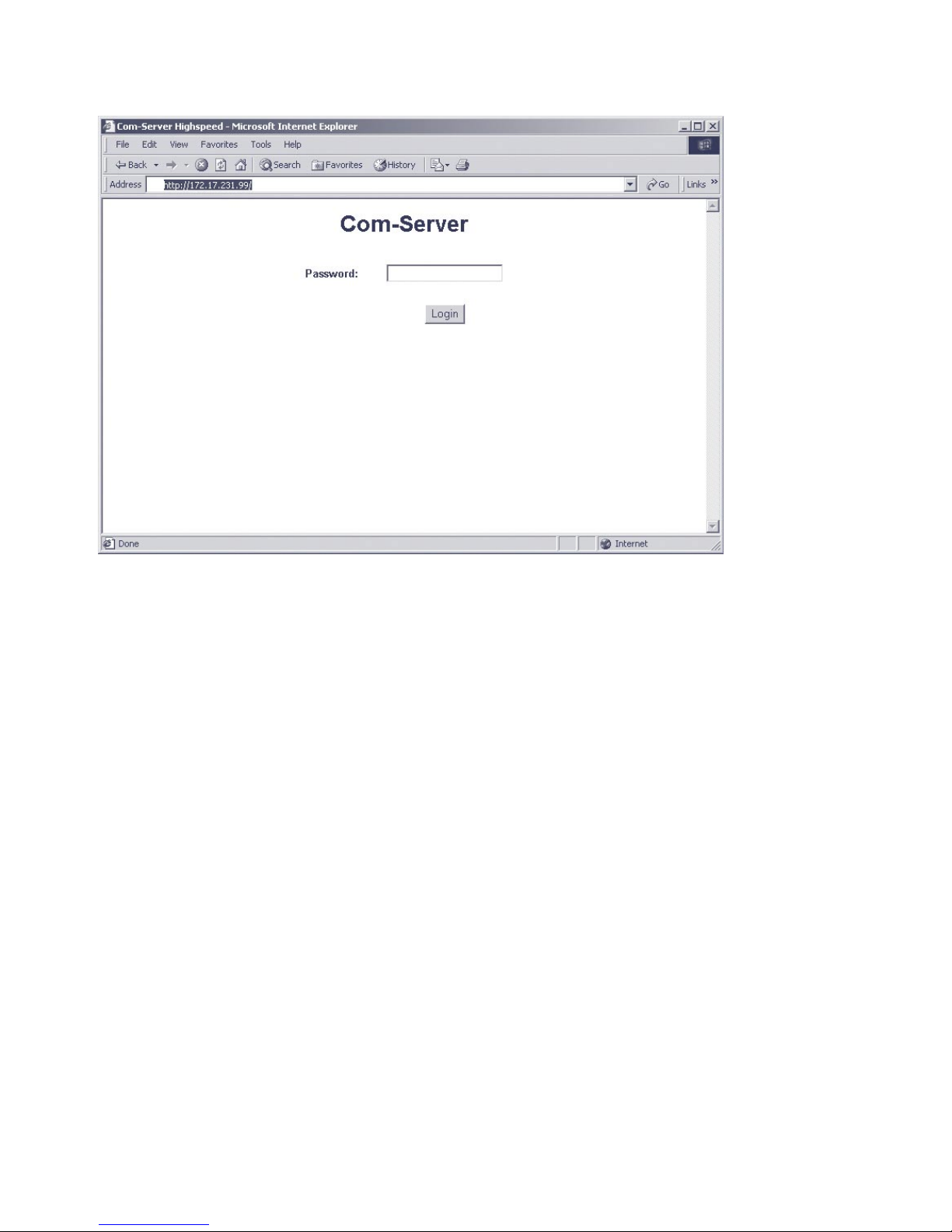
74
W&T Configuration access to the Com-Server
Navigation
Since the WBM of the Com-Server is session-oriented, you must
use backlinks and corresponding control buttons to navigate
to the individual Web pages. Using the Back function in the
browser can lead to problems in accepting the set parameters.
You can make as many settings as desired during a
configuration session. Pressing the Send button in the
respective pages pastes them to a clipboard. Once all the
settings have been made, always exit the configuration
session using Link Logout and the Save button there. Only
then are the settings you made copied into the non-volatile
memory of the Com-Server and activated.
Page 75
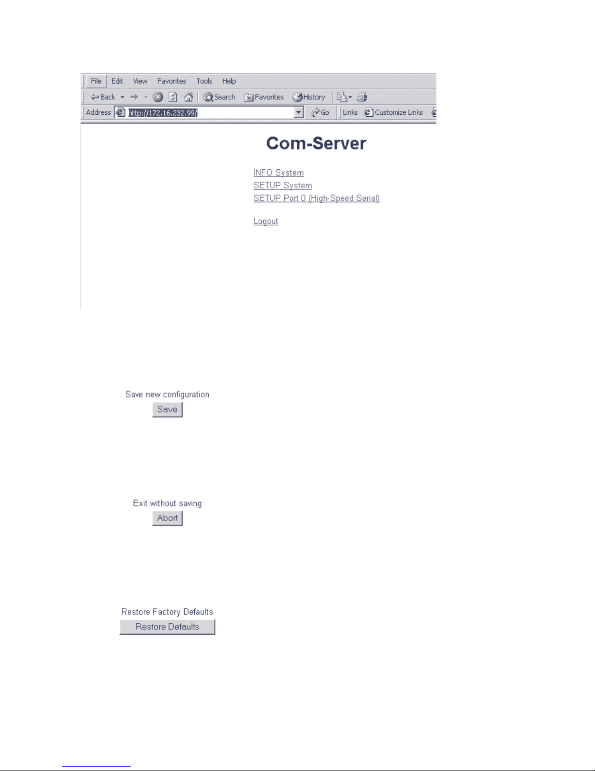
75
W&T Configuration access to the Com-Server
Subject to error and alteration
The logout page then offers the following possibilities for
ending the configuration session:
n
Clicking on the Save button causes the Com-Server to save
all the changes you made in its non-volatile memory and
quits the configuration session.
n
Clicking on the Abort button causes the Com-Server to
reject all the settings you made and quits the configuration
session.
n
Clicking on the Restore Defaults button resets the Com-Server to its original factory setting. All settings including the
network parameters IP address, subnet mask and gateway
address are lost.
Page 76
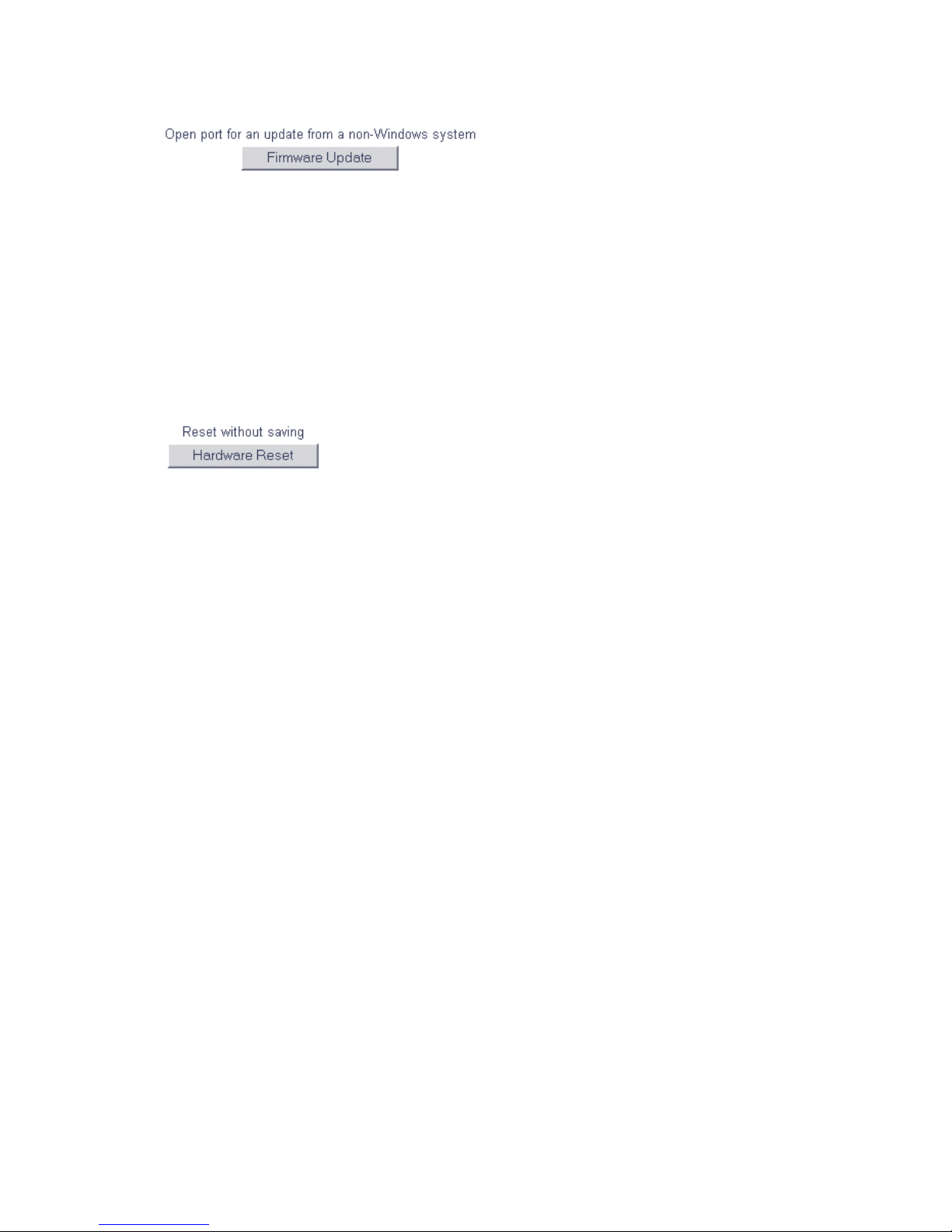
76
W&T Configuration access to the Com-Server
n
Clicking on the Firmware Update button activates the mode
in which the Com-Server expects a firmware update via TFTP
protocol (see section Firmware Update of the Com-Server).
Update mode can be exited only by complete transmission
of a valid firmware or by interrupting the supply voltage.
When using the WuTility tool for the firmware update, this
mode is automatically started. In this case a manual start is
not necessary.
n
Pressing the Hardware Reset button restarts the Com-Server, comparable with interrupting the supply voltage. Data
from any other opened connections to the Com-Server are
lost in this event.
1
The functions located on the logout page of the Com-Ser
ver can also be found in the Telnet menu branch SETUP
System r Setup TCP/IP.
Page 77

77
W&T
Subject to error and alteration
7 The basis configuration of the Com-Server
Here follows the explanation of all the configuration possibilities related
to the Com-Server operating system and which are not directly related to
the serial ports. The arrangement and function of the individual
parameters within the menu structure are for the most part identical with
Telnet and the Internet browser.
. Menu: INFO System
. Menu: SETUP System
. Saving your settings
Page 78

78
W&T The base configuration of the Com-Server
7.1 Saving your settings
When configuring using either Telnet or Web Based Management, all the changes are first saved only temporarily in the
Com-Server. To make sure the settings remain intact even
after a reset or power failure, each configuration session
must be ended with an explicit save procedure.
Telnet
From the main menu select SAVE Setup. Respond with y to
the Save Changes ? prompt. If a correct entry was made, the
text Saving… will appear on the monitor, and the Com-Server saves all the settings you made in its non-volatile
memory. Once the data have been saved, they are activated
each time the Com-Server is turned on or reset.
Entering anything other than y or simply pressing the ENTER
key returns you to the main menu without saving the values.
1
Exceptions are the network parameters IP address,
subnet mask and gateway, since these are also relevant
for the running configuration session. To save and activate
these you must enter q to quit the Telnet configuration after
executing SAVE Setup. The Com-Server then autonomously
performs a reset and only then begins to work with the new
settings.
Browser - WBM
Exit the configuration session using the Link Logout and
click on the Save button.
Page 79

79
W&T The base configuration of the Com-Server
Subject to error and alteration
7.2 Menu: INFO System
This menu allows you to call up device-specific parameters
such as the version njmber and creation date of the
firmware, MAC address of the unit, etc.
n Cable type
Shows the current Ethernet connection of the Com-Server
(10BaseT or 100BaseT).
n MAC address
Shows the Ethernet address of the Com-Server. This
number is factory set and registered. It cannot be
changed.
n SOFTW Date/Rev.
Shows the creation date and version number of the
operating software in flash.
n HARDW Rev.
Shows the version status of the Com-Server hardware.
n Run Time
Shows the time in hours and minutes since the last ComServer restart.
Page 80

80
W&T The base configuration of the Com-Server
7.3 Menu: SETUP System
This menu is for configuring all the parameters that pertain to
the Com-Server operating system and are independent of the
serial interface.
7.3.1 Menu: SETUP System r Setup TCP/IP
n IP-Address (Default = 0.0.0.0)
Enter here the IP address if you want to change it. Please
note that this number is not freely selectable, but rather
needs to be specified based on the network address of the
TCP/IP network. The format corresponds to the normal
syntax (e.g. 172.16.231.5).
n Subnet Mask (Default = 255.0.0.0)
The subnet mask only needs to be entered if the Com-Server will be making connections to another subnet. Enter the
subnet mask of the subnet in which the Com-Server is
located (e.g. 255.255.255.0). Please note: The IP address
determines the network class. From this is derived a default
subnet mask (e.g. 255.255.0.0 for a Class B network).
n Gateways (Default = 0.0.0.0)
In this menu branch the IP address of the standard gateway
or router can be configured. If you have not configured
fixed routes, the standard gateway is used for all network
packets whose destination IP address is not in the local
subnet.
n Route 1-4 (Destination, Netmask, Gateway)
In addition to the standard gateway, up to four fixed
routes can be defined. Packets whose destination
addresses are in the networks configured here
(=destination) are always sent through the gateway
assigned to this route. A fixed route is only accepted and
stored by the Com-Server if the following check is true:
Destination AND Netmask == Destination
Page 81

81
W&T The base configuration of the Com-Server
Subject to error and alteration
1
Changes to the system parameters IP-Address,
Subnet Mask, Gateway and Route 1-4 cannot be
activated right after saving. The Com-Server will use these
values only after closing the current Telnet connection using q.
n DNS Server (Default: 0.0.0.0)
The entry contains the IP address of the DNS server (Domain
Name System). The latter is needed in all client modes of
the Com-Server (TCP, UDP, Telnet, FTP client) if the
destination system is to be stored in the configuration not
as a numerical IP address, but rather in the form of a host
name or URL. The name is resolved by the Com-Server is
done via UDP using standard port 53 reserved for the DNS.
The Time-To-Live of the IP address resolved for a host name
is determined by the Time-To-Live parameter contained in
the response from the DNS server. After the name has been
successfully resolved this time is displayed in the menu
item SETUP Port 0 r Port State r Connection State.
n MTU – Maximum Transfer Unit (default: 560)
This value determines the maximum size of a TCP/IP packet.
It refers to the number of bytes (excluding header) that can
be sent in a packet. The smaller the MTU, the more network
buffer overall is available in the Com-Server. The selectable
range begins at 560 and ends at 1460 bytes. The values can
be set in increments of 128 bytes (automatic correction).
n DHCP Client (Default: 1 = ON)
The DHCP protocol is activated with the factory settings
(menu entry = 1). The Com-Server attempts to find a DHCP
server and get an IP address from it. Entering 0 deactivates
DHCP and the Com-Server works statically with the IP
address assigned to it. More information on how DHCP
works can be found in the section IP Assignment via DHCP
Protocol.
Page 82

82
W&T The base configuration of the Com-Server
1
To prevent unintended address assignments or
changes, we recommend deactivating the DHCP,
BOOTP and RARP protocols if they are not expressly used in
the respective network environment.
n BOOTP Client (Default: 1 = ON)
The factory setting is for BOOTP protocol deactivated (menu
entry = 0). Entering 1 activates the function and the ComServer attempts to obtain an IP address from a BOOTP server
after each reset. More information on how BOOTP works can
be found in the section IP Assignment via BOOTP Protocol.
1
To prevent unintended address assignments or
changes, we recommend deactivating the DHCP,
BOOTP and RARP protocols if they are not expressly used in
the respective network environment.
n WBM Port (Default: 0000)
The decimal value specifies the TCP port under which the
Web Based Management (WBM) of the Com-Server is
accessible from an Internet browser. The factory setting
is 0000, which means WBM is deactivated. If for example
you set a value of 80 (= standard HTTP port), you can
open the Web configuration from an Internet browser
without explicitly specifying the port number. It is sufficient
to enter the IP address or the name of the Com-Server stored
in the DNS. When using other port numbers, these must be
given in the address line of the browser as well separated
by a colon (e.g., http)://172.17.231.49:1234).
n Keep Alive Time (sec) (Default: 0 = OFF)
If the keep-alive check is activated by entering and saving a
value in second ticks, all TCP connections are monitored for
network-side data traffic. If there is no network traffic within
the set time, the Com-Server generates a keep-alive packet.
If the partner does not answer this packet, the connection
is reset in the Com-Server. This deletes any data still
contained in the serial in- and output buffers.
Page 83

83
W&T The base configuration of the Com-Server
Subject to error and alteration
Example: A TCP client has opened a connection to TCP
server port 8000 of the Com-Server and the network
connection is interrupted. After the set keep-alive time plus
2s for two repetitions has elapsed, the Com-Server closes
the connection and is again ready for any other clients.
n Retransmission Timeouts (ms) (Default: 240)
This timeout determines what time must elapse before
network packets are repeated if necessary. In most
networks the default setting of 240ms can be used. Only
when there are very long latency times between the ComServer and its respective communications partner would
you need to increase this value.
7.3.2 Menu: SETUP System r Telnet Password
Here you may specify an 8-character hexadecimal password
(valid charcters = 0...9 and a...f) for protecting the
configuration menu from unauthorized access. The factoryset password is 00000000. With the password you have
unrestricted access to the Com-Server‘s configuration menu.
You are prompted for a valid password as soon as the Telnet
connection for the configuration port is opened. An incorrect
entry denies access to the Com-Server‘s configuration port.
1
Resetting or changing any parameters including the
password is only possible if you know the old
password. Make sure you write it down and keep it in a safe
location.
Page 84

84
W&T The base configuration of the Com-Server
7.3.3 Menu: SETUP System r System Password
The system password, which consists of any 31 (max.)
characters, protects against any subsequent configuration
and control access to the Com-Server.
· 1111: Telnet configuration menu
· [WBM port]: Web Based management (if enabled)
· 8003: Read the configuration file
· 8004: Write the configuration file
· 8888: Reset Com-Server
· 9084, 9184, 9284, 9384: Reset port status A-D
· 9094, 9194, 9294, 9394: Control port A-D
· 161 (UDP, SNMP)
On Telnet port 1111 and on WBM port the system password is
prompted as soon as the connection is opened. For all other
associated TCP ports the password must be null-terminated
(=[password] + 0x00) and sent to the Com-Server no later than
2s after the TCP connection has been established.
Queries from SNMP managers are only responded to by the
Com-Server if the community corresponds to the system
password.
For additional information on using system passwords in
conjunction with the configuration and control ports, see the
section „Expanded Services of the Com-Server“.
1
The system password is on a higher level than the
Telnet password. This means that after assigning a
system password, a previously set Telnet password may
become invalid, so that the system password must be used
for all password prompts.
Page 85

85
W&T The base configuration of the Com-Server
Subject to error and alteration
7.3.4 Menu: SETUP System r System Name
The freely configurable system name consisting of max. 31
characters is used to identify the Com-Server. This name is
displayed as an opening message in the client for all Telnet
sessions.
The factory default setting for the system name is COMSERVER_
followed by the last three places of the Ethernet address. For
example the factory set system name of a Com-Server with the
Ethernet address 00:c0:3d:01:02:03 is COMSERVER_010203.
When using DHCP protocol the system name is also used for
identification by the DHCP server.
7.3.5 Menu: SETUP System r Flash Update
Before you activate the update mode, make sure that you have
quit any active network connections. Then confirm with „y“. The
update mode is indicated by lighting of the Status LED on the
Com-Server.
Activate this mode when you want to perform an update of the
Com-Server operating software over the network using the
management tool WuTility or TFTP (see Firmware update of the
Com-Server).
1
You may quit the update mode only by either
completely performing the update or by means of a
reset, i.e. turning off the power!
7.3.6 Menu: SETUP System r Factory Defaults
Enter a y to reset all the parameters. The configuration is then
in its factory preset state. The Com-Server closes the Telnet
Page 86

86
W&T The base configuration of the Com-Server
connection. Then it performs a software reset in order to
activate the new configuration.
1
Resetting the non-volatile memory causes loss of all the
settings which deviate from the default values, including
the IP address.
7.3.7 Menu: SETUP System r Reset
Select this menu item to perform a software reset on the ComServer. First your Telnet connection is properly closed.
1
All data from any still open network connections are
lost
Page 87

87
W&T The base configuration of the Com-Server
Subject to error and alteration
7.4 Menu ... r TCP/IP Mode r System Options
In this menu branch you can set specific system parameters.
n Network Delay [10ms-Ticks]
Default: 0000
This value specifies the minimum delay time of the ComServer after serial data have arrived. After this time has
expired, it packs the data into a network packet and sends
them to the respective communications partner. The default
setting 0 means the attempt is made to send the data as
quickly as possible. The resulting high time transparency
does however bring with it the drawback of a higher number
of network packets.
If the serial transmission takes place in predictable block
sizes, this value can be adjusted to optimize the network
load. There is also the advantage that the serial blocks are
transmitted within a network packets, so that they arrive at
the receiver bundled.
Example:
You are using serial data blocks of 25 bytes each and
transmission parameters of 9600 baud, 8 data bits, no
parity and 1 stop bit. Each block thus has a length of
approx. 26ms (1/9600 * 10 bits * 25 bytes). If the network
delay is set here to a value of 3 (=30ms), each block is sent
to the receiver with a network packet.
1
The situation described here applies only to a non-
overloaded and error-free network. If there are
interruptions in the data flow on the network side, any
serially accumulated data are also sent in larger network
packets.
Page 88

88
W&T The base configuration of the Com-Server
n Telnet Echo
Default: active
When opening a Telnet session, negotiation between the
stations takes place on the network side to determine who
will generate the echo of the characters sent by the client.
Either the client application generates a local echo, or the
Telnet server generates a remote echo by immediately
returning all received data. The Telnet echo option on the
Com-Server is defined as follows:
Telnet Echo = active
The Com-Server negotiates a remote echo with the client
application, and the local echo is turned off. In this case the
device serially connected to the Com-Server must generate
the echo.
Telnet Echo = disabled
The Com-Server tells the client application when opening
the connection that it will not generate an echo, which
results there in activation of the local echo. The local echo
may have to be manually activated on the Telnet client.
n Flush Buffer
Default: active
If this switch is active, the serial buffer is cleared each time
a new connection is opened; any residual data which cannot
be transmitted (e.g. handshake stop of the serial terminal
device) are thus lost. But if you connect a terminal device to
the Com-Server which for example requires a longer handshake stop for program reasons, you can prevent clearing of
the buffer by deactivating the switch. In this way multiple
connections can be opened one after the other on the
network side and the data are accumulated in the buffer
until they are sent.
Page 89

89
W&T
Subject to error and alteration
8 Configuration of the serial port
. Configuring the serial transmission parameters
In addition to the usual settings for baud rate, data bits, parity and stop
bits, the various handshake procedures and available special functions of
the individual control signals are explained here.
Page 90

90
W&T Configuration of the serial port
8.1 The serial parameters (Menu: UART Setup)
Like any serial device, the Com-Server port must be set to
match the communication parameters of its partner. All the
RS232 parameters relevant for operation are configured in the
Setup Port x r UART Setup menu. In addition to the usual
settings for baud rate, data bits, parity and stop bits, here you
can also specify the handshake procedure as well as the
functions of the individual control signals and the UART-FIFOs.
1
The settings only become active after saving with
SAVE Setup or pressing the button Save on the Logout
page. Please note that saving the parameters deletes all data
currently located in the ComServer port buffers.
8.1.1 Baud rate, Data bits, stop bits, parity
The desired transmission parameters can be selected by entering the corresponding designation in the respective branch of
the menu tree. Invoking Save Setup in the master menu saves
the changes you made in the non-volatile memory of the ComServer and simultaneously activates them.
Freely selectable baud rate (Special Baud Divisor)
In the submenu Special Baud Divisor you can enter any desired
divisor for generating the baud rate. This makes it possible to
work even with non-standard baud rates. The baud rate and
divisor are calculated using the following formulas:
Models 58631, 58431
Divisor=
11,0592*10
6
16*Baudrate
Baudrate=
11,0592*10
6
16*Divisor
Page 91

91
W&T Configuration of the serial port
Subject to error and alteration
Models 58031, 58034, 58633, 58231, 58331, 58334
Divisor=
7,3728*10
6
16*Baudrate
Baudrate=
7,3728*10
6
16*Divisor
The currently configured baud rate is displayed when selecting
the submenu SETUP Port x (serial) r UART Setup.
By allowing any divisor, very high baud rates are possible.
Please note in this connection that the upper limit for a bundled
data stream is 230.4 kbps.
1
The indicated value refers to a handshake-controlled
half-duplex transmission with no parity and a non-loaded
network.
8.1.2 The handshake modes
(SETUP Port x r UART Setup r Handshake)
This menu provides three standard modes for flow control of
the serial port. As opposed to these predefined handshake
profiles, you can use the Special submenu to specify the
function of each control signal individually. This allows you for
example to use hardware-controlled TCP connection control.
Details on the control line functions are contained in the
description of the submenu.
n Hardware Handshake
When using hardware handshake, the individual RS232
signals perform their factory-set functions as described in
the section „RS232 Interface“. Please note that the meaning
of the individual signals may be changed by the respective
user software.
Function of the control signal: RTS: Flow Control
DTR: Show Connection
CTS: Flow Control
DSR: NO
Page 92

92
W&T Configuration of the serial port
n Software Handshake
The software handshake is implemented using the two ASCII
characters (11H)=XON and (13H)=XOFF. In the standard
setting Software Handshake these two codes are considered
by the Com-Server as control characters and are filtered out
from the actual data flow in both directions. This filtering
can be turned off individually for each data direction in the
Special submenu.
Function of the contorl signal:RTS: NO (Default HIGH)
DTR: NO (Default HIGH)
CTS: NO
DSR: NO
n NO Handshake
Turns off any hardware or software flow control for the serial
interface. All the data are output to the connected terminal
device regardless of the status of the inputs CTS and DSR.
Any impending overflow of the serial input buffer is not
signalled by the Com-Server. The setting NO Handshake
makes sense for any data transmission that uses a serial
protocol for data integrity or flow control.
Function of the contorl signal: RTS: NO (Default HIGH)
DTR: NO (Default HIGH)
CTS: NO
DSR: NO
n Special
Here it is possible to configure the function of the control
lines differently from the three predefined protocols. In
addition, the filter function of the „Xon“ and „Xoff“
characters used for the software handshake can be
ifnluenced. Toggle between on and off by entering the
menu number of the desired function. Settings made here
are correspondingly overwritten by selecting one of the
three predefined handshake modes.
Page 93

93
W&T Configuration of the serial port
Subject to error and alteration
n Pin: RTS & Pin: DTR
The following functions can be assigned to the outputs
RTS and DTR:
1. Flow Control – If this function is turned on, the
Com-Server handles the RS232 flow control through the
corresponding output. The ready state for serial data is
signaled by a HIGH signal (+3...12V). If the memory limit
of the input buffer is reached, the line is set to LOW (-
3...-12V).
2. Show Connection – The output is switched to the
serial port depending on an existing TCP connection.
HIGH (+3...12V) indicates an existing connection.
3. NO (Default=HIGH) – The outputs are not used by
the Com-Server and carry a constant HIGH level
(+3...12V). A network application can use the control
port of the Com-Server (see „Enhanced services of the
Com-Server“) to temporarily influence the level.
4. NO (Default=LOW) – The outputs are not used by
the Com-Server and carry a constant LOW level (-3...12V). A network application can use the control port of
the Com-Server (see „Enhanced services of the Com-Server“) to temporarily influence the level.
n PIN: CTS und PIN: DSR
The inputs CTS and DSR can be assigned the following
functions:
1. Flow Control – The serial flow control is performed
using the corresponding pin. Serial data are output only
if the input was set to HIGH (+3...12V) by the connected
terminal device.
2. OPEN/CLOSE – Connection This option for TCP
connection building and ending can be used to control
connection building and ending in all Com-Server client
operating modes. If the IP address and the TCP port are
stored in the Com-Server, a HIGH level (+3...12V) on the
corresponding input establishes a connection. The
connection is closed with a LOW level (-3...-12V).
Page 94

94
W&T Configuration of the serial port
3. Accept only by HIGH – Connection establishment
of a TCP client is only accepted if a HIGH level (+3...12V)
is present on the corresponding input. Likewise the
connection is rejected when there is a LOW level.
4. NO (Manual IN) – The selected input is ignored by
the Com-Server and plays no role either in data
transmission or connection control.
n XON/XOFF
Here the handshake can be configured for XON/XOFF
separately for each data direction. "XON/XOFF Receive"
switches processing of this control character for serial
receiving on: After receipt of an XOFF sent by the RS232
terminal device, the Com-Server stops serial data output
until it receives an XON. If "XON/XOFF Send" is turned
on, the Com-Server generates an XOFF when it is no
longer able to receive serial data.
n XON/XOFF (Filter)
If XON/XOFF is turned off for flow control, this option
can be used to separately determine for both data
directions whether the Com-Server filters these control
characters out of the actual data.
1. Send-Filter (Data direction r serial)
If this option is turned on and XON or XOFF characters
occur in the actuqal data, the Com-Server filters them
out and does not pass them along to the terminal
device. Select this mode generally for bi-directional
RS232 connections, since otherwise you will have
problems with data traffic. If the Send-Filter option is
turnd off, all the data including the XON and XOFF
characters are sent unfiltered on the RS232 interface.
This mode only makes sense if the connected terminal
device is a graphics printer whose data stream can be
expected to contain handshake characters.
Page 95

95
W&T Configuration of the serial port
Subject to error and alteration
2. Receive-Filter (Data direction r network)
If this option is turned on, the Com-Server interprets the
XON and XOFF characters sent by the serial terminal
device as control bytes and does not insert them into
the network data stream. This ensures that the recipient
in the network only gets actual user data. If Receive-Filter is turned off, the XON and XOFF characters sent by
the serial terminal device are transmitted to the network
together with the actual user data. This mode requires
of the respective recipient in the network that it be able
to separate actual data from control data.
The currently selected parameters are shown in the top line of
the „UART Setp“ menu. As soon as a parameter is changed, until
the parameters are saved this display does not show the
configuration with which the Com-Server port is currently
working!
Display format:
[Baud], [Parity], [Data bits], [Stop bits], [Handshake], [FIFO]
Possible values for the handshake variables are:
[N]
[H]
[S]
[Special]
Send-Filter
---
---
ON
---
Receive-Filter
---
---
ON
---
No handshake
Hardware handshake
Software handshake
XON/XOFF
Special setting
configuration menu
"Handshake-Special"
Page 96

96
W&T Configuration of the serial port
8.1.3 FIFO Send/Rec
The submenu allows the FIFO memory of the serial receive
module to turn on and off. Models 58031, 58034, 58231,
58331, 58334 and 58633 also make it possible to set various
trigger thresholds.
Especially when transmitting large quantities of data at high
baud rates (above 57.6 Kbaud), it is recommended that you
turn on the FIFOs in order to reduce the system load. If for
example when working with serial protocols you require as short
a delay in data transmission as possible, the FIFOs should be
turned off.
Page 97

97
W&T
Subject to error and alteration
9 The protocol stack of the Com-Server
. Services of the Com-Server
. Addressing in the TCP/IP network
. The serial ports as seen from by network
Page 98

98
W&T The protocol stack of the Com-Server
9.1 Services of the Com-Server
The actual data are exchanged between the application and the
Com-Server port using TCP/IP or UDP/IP. Which protocol is
selected and the type of connection (Client or Server) for data
transmission depends on the application. The following table
shows the various modes of the serial Com-Server port.
Menu: Setup Port x r TCP/IP Mode
"TCP-Server" Mode
"TELNET-Server" Mode
"FTP-Server" Mode
"TCP-Client" Mode
"UDP-Client" Mode
"TELNET-Client" Mode
"FTP-Client" Mode
"Box to Box" Mode
"IP Bus Mode
SLIP-Router
Serial Socket Interface
--
--
--
r TCP-Client
r UDP-Client
r Telnet-Client
r FTP-Client
r Box to Box
r IP Bus Mode
r SLIP Router
r Ser. Socket Interface
In addition to simple transmission of the data, a dedicated
TCP port provides functions for monitoring and configuring
the serial interface (see Enhanced services of the Com-Ser-
ver).
The Com-Server supports the following protocols:
••
••
• ARP, RARP, ICMP (Ping), RIP, DHCP, BOOTP, DNS, SNMP
••
••
• IP, TCP (Client / Server), UDP (Client / Server)
••
••
• FTP (Client / Server), Telnet (Client / Server), HTTP (WBM)
••
••
• SLIP
Page 99
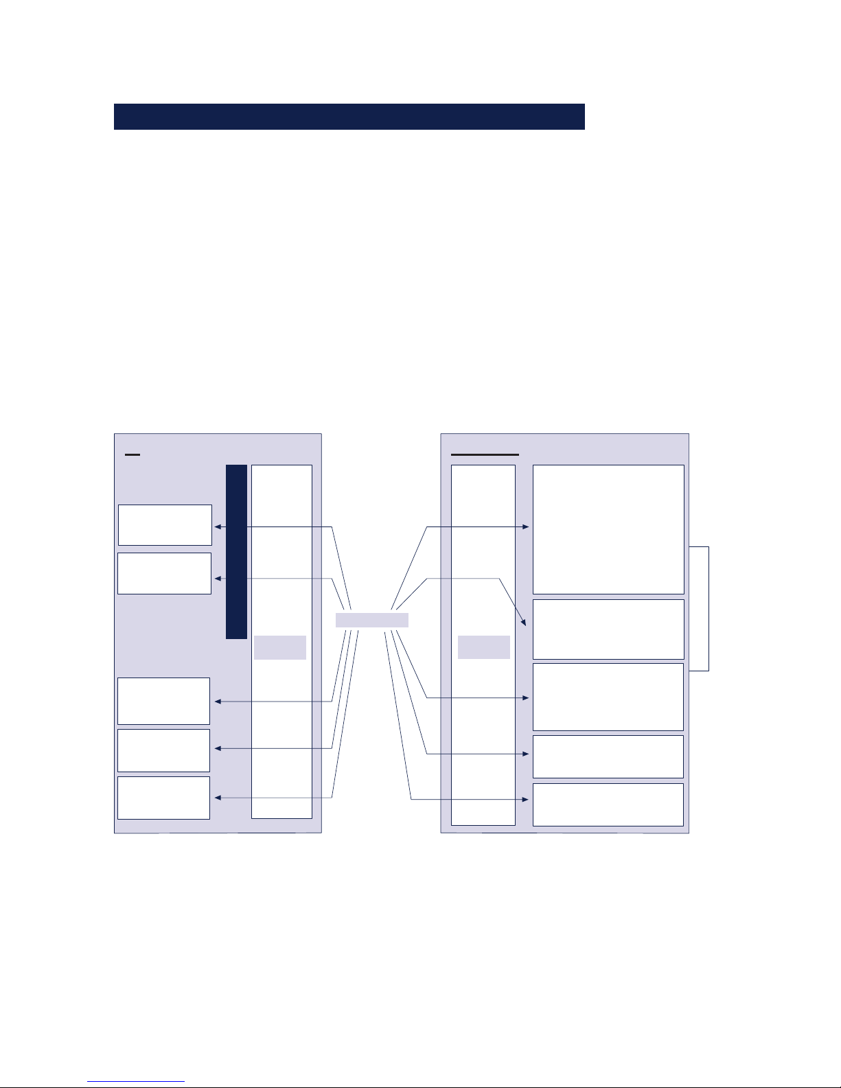
99
W&T The protocol stack of the Com-Server
Subject to error and alteration
9.2 Addressing in the TCP/IP Network
Addressing in the TCP/IP network is done in two steps. FIrst
the network station itself is addressed with the IP address,
then the services of this network station are addressed with
TCP port numbers. Each IP address must be unique
throughout the network, and each port number must be
unique on the network station.
Addressing the serial ports is done analogously. The ComServer is assigned an IP address upon installation (see
Assigning the IP address). This address is used to access the
Com-Server. The individual services are factory addressed
using the following port numbers.
RS232, RS422/485
PC
User
programs
TCP/IP-
Stack
Com-Server
TCP/IP-
Stack
IP addr.:
172.0.0.1
ETHERNET
FTP
- Server
- Client
Standard tools
Datagrams
- UDP server
- UDP client
SOCKET-API
IP addr.:
172.0.0.9
Streams
- TCP server
- TCP client
Special functions (server)
- Controlport
- Reset port
- Reset Com-Server
- EEPROM Download
- EEPROM Upload
Datagrams
- UDP server
- UDP client
- UDP Info packet
- UDP SNMP
FTP
- Server
- Client
Telnet
- Server
- Client
Streams
- TCP server
- TCP client
Telnet
- Server
- Client
- Configuration
tool (server)
HTTP
- Configuration with
Web Based Management
HTTP
- Client
(Browser)
If in a particular case the factory assigned port number canot
be used, you may modify it (see Configuration of the TCP/IP
modes).
Page 100
100
W&T The protocol stack of the Com-Server
9.3 The protocol stack of the Com-Server
There are several possibilities for transporting serial interface
data. The Com-Server port supports the standard protocols FTP
and Telnet. It also allows you to transport the data on the socket interface level directly as TCP streams or UDP datagrams inother words, without any additional higher-order protocol.
The illustration below shows the protocol layering in the ComServer:
FTP
Client/Server
Telnet
Client/Server
Client/Server Client/Server
Standard protocols:
Socket interface
applications:
TCP-Streams UDP-
Datagrams
SOCKET-API
IP (Internet protocol) ICMP
Ethernet
Each mode is explained individually in the following sections.
The server mode does not have to be configured separately; it
is activated when a client of a TCP/IP station directs a
connection request to the server in the Com-Server.
The client processes in the Com-Server need to be set up in the
configuration menu of the Com-Server port.
9.3 1 Data transfer per TCP/IP and UDP/IP sockets
Using the socket API (under Windows WinSock, under UNIX
Berkley Sockets, ...) it is possible to implement a variety of
applications in the form of client or server processes on TCP/IP
computers. The API offers all the functionality for transporting
data over the network. You can customize your application program - that is, the further processing and evaluation of the data
- for your particular requirements.
The Com-Server provides both of the protocols possible on the
socket level for data transfer: Client/server process with TCP
 Loading...