

W&T 58631, 58641, 58034, 58031, 58231 User Manual
...
Manual
Com-Server Highspeed
Release 2.10, October 2006
Type 58631, 58641,
58633, 58031,
58034, 58231,
58431, 58432,
58331, 58334
Com-Server Firmware 1.52 or higher
W&T

W&T
© 10/2006 by Wiesemann und Theis GmbH
Subject to error and alteration:
Since it is posssible that we make mistakes, you mustn’t use
any of our statements without verification. Please, inform us
of any error or misunderstanding you come about, so we can
identify and eliminate it as soon as possible.
Carry out your work on or with W&T products only to the
extent that they are described here and after you have
completely read and understood the manual or guide. We are
not liable for unauthorized repairs or tampering. When in
doubt, check first with us or with your dealer.

W&T
Introduction
The Com-Server models 58631, 58641, 58633, 58031, 58034,
58231, 58431, 58432 58331 and 58334 represent a uniform
platform for linking serial interfaces such as RS232, RS422/485
to TCP/IP networks.
In addition to all the standard applications implemented in
the Com-Servers, this reference manual also describes
methods of integrating Com-Servers into your own
applications.
Com-Server Highspeed models
Model
No.
58631
58631/UL
58641
58633
58031
58034
58231
58431
58432
58331
58334
Supply
voltage
12 - 24V
AC/DC
12 - 24V
DC
PoE or
24V AC/DC
12 - 24V
AC/DC
100-250V~
50-60Hz
100-250V~
50-60Hz
5V +/-5%
5V +/-5%
5V +/-5%
5V +/-5%
5V +/-5%
Network
interface
10/100BaseT
autosensing
10/100BaseT
autosensing
10/100BaseT
autosensing
10/100BaseT
autosensing
10/100BaseT
autosensing
10/100BaseT
autosensing
10/100BaseT
autosensing
10/100BaseT
autosensing
10/100BaseT
autosensing
10/100BaseT
autosensing
10/100BaseT
autosensing
Serial interface
1 x Interface module
RS232/RS422/RS485
1 x Interface module
RS232/RS422/RS485
1 x Interface module
RS232/RS422/RS485
3 x Interface module
RS232/RS422/RS485
1 x Interface module
RS232/RS422/RS485
4 x Interface modules
RS232/RS422/RS485
1 x Interface module
RS232/RS422/RS485
1 x TTL (optional
RS232, RS422/485)
1 x TTL + RS485 2-wire
(optional RS232, RS422)
1 x Interface module
RS232/RS422/RS485
4 x Interface modules
RS232/RS422/RS485
Housing
Top hat rail
housing
Top hat rail
housing
Top hat rail
housing
Top hat rail
housing
Desktop metal
housing
Desktop metal
housing
Compact metal
housing
none (OEM)
none (OEM,
credit card format)
19" version
19" version

W&T
Content
1 Quickstart 9
1.1 Flow chart – Network installation using WuTility 10
1.2 Overview of configuration menu 11
1.3 Factory Default settings 12
2 Assigning the IP address 13
2.1 Configuring network parameters with WuTility 14
2.2 Assigning the IP using the ARP command 18
2.3 Serial assigning of IP, subnet mask and gateway 20
2.4 Assigning the IP using DHCP protocol 24
2.5 Assigning the IP using BOOTP protocol 28
2.6 Assigning the IP using a RARP server 30
3 Form factors 31
3.1 Com-Server Highspeed Industry 32
3.2 Com.Server Highspeed Isolated 58633 33
3.3 Com-Server Highspeed Office 34
3.4 Com-Server Highspeed 19“ 35
3.5 Com-Server Highspeed OEM 58431 36
3.6 Com-Server Highspeed compact 58231 37
4 Supply voltage 39
4.1 Com-Server Highspeed Industry and Isolated 40
4.2 Com-Server Highspeed Industry 58631/UL 41
4.3 Com-Server Highspeed Industry PoE 42
4.4 Com-Server Highspeed Office 43
4.5 Com-Server OEM and compact 44
4.6 Com-Server Highpeed 19“ 45
5 Interfaces and displays 47
5.1 Ethernet connection 48
5.2 RS232/422/485 combi-module 50
5.2.1 Opening the Com-Server 50
5.2.2 Mode selection 51
5.2.3 RS232 mode (factory default) 51
5.2.4 RS422/485 mode 53

5
W&T
Subject to error and alteration
5.3 Interface for the OEM-Com-Server 58431 56
5.4 Option: 20mA interface 58
5.5 Interfaces for the OEM-Com-Server 58432 60
5.5 LED displays 63
6 Configuration access to the Com-Server 65
6.1 Configuration menu structure 66
6.2 Configuration via Telnet 68
6.3 Configuration via Browser - Web Based Management 71
6.3.1 Activating WBM with the WuTility-Tool 71
7 The basis configuration of the Com-Server 77
7.1 Saving your settings 78
7.2 Menu: INFO System 79
7.3 Menu: SETUP System 80
7.3.1 Menu: SETUP System r Setup TCP/IP 80
7.3.2 Menu: SETUP System r Telnet Password 83
7.3.3 Menu: SETUP System r System Password 84
7.3.4 Menu: SETUP System r System Name 85
7.3.5 Menu: SETUP System r Flash Update 85
7.3.6 Menu: SETUP System r Factory Defaults 86
7.3.7 Menu: SETUP System r Reset 86
7.4 Menu ... r TCP/IP Mode r System Options 87
8 Configuration of the serial port 89
8.1 The serial parameters (Menu: UART Setup) 90
8.1.1 Baud rate, Data bits, stop bits, parity 90
8.1.2 The handshake modes 91
8.1.3 FIFO Send/Rec 96
9 The protocol stack of the Com-Server 97
9.1 Services of the Com-Server 98
9.2 Addressing in the TCP/IP Network 99
9.3 The protocol stack of the Com-Server 100
9.3 1 Data transfer per TCP/IP and UDP/IP sockets 100
10 Data transfer per TCP/IP sockets 103
10.1 The Com-Server as TCP server 104
10.1.1 Configuration of the local port number 104
10.1.2 Optional settings 105

W&T
10.2 The Com-Server as TCP-Client 107
10.2.1 TCP client mode with fixed destination system 108
10.2.2 TCP client mode with serial addressing 111
10.2.3 Optional settings 112
10.2.4 Deactivating TCP client mode 114
10.2.5 Application:
Client/Server mode between Com-Server-Ports 114
11 Data transfer per UDP 117
11.1 The Com-Server as UDP peer 118
11.1.1 Setting the local UDP port number 119
11.1.2 UDP clientmode with fixed destination system 120
11.1.3 UDP client mode with serial addressing 121
11.1.4 Optional settings 123
11.1.5 Deactivating UDP mode 124
12 The Windows COM port redirector 125
12.1 Virtual COM ports 126
13 Box-to-Box mode 129
13.1 Box-to-Box mode 130
13.1.1 Configuring Box-to-Box mode 131
13.1.2 Optional settings 132
13.1.3 Deactivating Box-to-Box mode 132
14 Data transfer per FTP 135
14.1 The Com-Server as FTP server 136
14.2 The Com-Server as FTP client 138
14.2.1 Configuring the destination address and port no. 138
14.2.4 Deactivating FTP client mode 145
14.2.5 Application examples 145
15 Data transfer per Telnet 147
15.1 Com-Server as Telnet server 148
15.2 The Com-Server as Telnet client 149
15.2.1 Optional settings 151
15.2.2 Deactivating Telnet client mode 151

W&T
16 IP Bus mode 153
16.1 Function of the IP Bus mode 154
16.2 Configuring the IP Bus mode 155
16.2.1 Activating the master 155
16.2.3 Deactivating IP Bus Mode 156
17 The Com-Server as SLIP router 157
17.1 Configuring the SLIP mode 158
18 Serial Socket Interface 163
18.1 Serial Socket Interface 164
19 Status and error messages 165
19.1 Menu Setup Port x r Port State 166
20 Expanded services of the Com-Server 169
20.1 The control port 170
20.2 Reset Com-Server-Port 178
20.3 Software reset of the Com-Server 180
20.4 Uploading/downloading configuration data 181
20.5 Inventory taking per UDP/8513 183
20.6 SNMP management 186
21 Firmware update of the Com-Server 187
21.1 Where do I get the current firmware? 188
21.2 Network firmware update under Windows 189
21.3 Network firmware update under UNIX 190
Appendix 193
TCP/IP under Windows 9x 194
TCP/IP under Windows NT 195
Used ports and network security 196
Serial assignment of the IP address under Windows 200
Web application HTTP, SMTP, POP3 ... 204
WuTility - Inventory and management tool 206
Hardware reset to factory defaults 207
Technical Data 208
Declaration of conformity 215
Index 216

W&T

9
W&T
Subject to error and alteration
1 Quickstart
Already experienced users of Com-Servers will find on the two following
pages a flow chart with the essential steps for start-up as well as a
complete overview of the configuration menu. Detailed information can
be found then in the following sections.
10
W&T
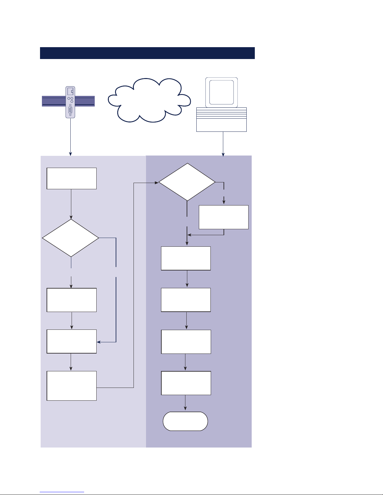
1.1 Flow chart – Network installation using WuTility
Select site
Connect
supply voltage
Com-Server Windows PC
with TCP/IP
WuTility
installed?
yes
Connect
network cable
Finish
Network
no
Obtain IP-
address, subnet
mask, gateway
address
Install
WuTility with
product CD
Button:
IP address
Enter IP address
subnet mask,
gateway
Start
WuTility
Select
device in
inventory list
Com-Server
with PoE?
no
yes

11
W&T
Subject to error and alteration
1.2 Overview of configuration menu
SETUP System Setup TCP/IP
Telnet Password
System Password
System Name
Flash Update
Factory Defaults
Reset
Link Speed (Auto, 10/100BT, HD/FD)
SETUP Port 0
SETUP Port 1
SETUP Port 2
SETUP Port 3
SAVE Setup
TCP Client
UDP Client
Serial Socket
Interface
Telnet Client
FTP Client
Box to Box
(TCP)
IP Bus Mode
SLIP Router
System Options
Server Port
Server IP/URL
Special Options
Port State
UART Setup
TCP/IP Mode
Connection State
Error State
Clear Port Mode
Baud
Parity
Data Bits
Stopbit
Handshake
FIFO S/R:
Standard Baudrates
Special Baud Divisor
230,4k
172,8k
115,2k
57600
38400
19200
9600
4800
2400
1200
600
300
150
110
757200
50
NONE
EVEN
ODD
8
7
None
Hardware
Software
Special
1
2
Pin: RTS
Pin: DTR
Pin: CTS
Pin: DSR
XON/XOFF
XON/XOFF (Filter)
FIFOs OFF
FIFOs ON
disable
8/8
16/16
32/56
56/60
Local Port TCP/UDP Inactivity Timeout
Connect. Timeout
Disconnect Char
Dispatch String 1
Dispatch String 2
Client: "C"+Addr
Response Mode
Server Port
Server IP/URL
Special Options
Serial Coding
Serial Protocol
Dispatch String 1
Dispatch String 2
Client: "C"+Addr
Disconnect Char
Write: "C"+Addr
Serial Protocol
Serial Coding
Protocol Char
Server Port
Server IP/URL
Special Options
Disconnect Char
Inactivity Timeout
Serial 0d -> 0d00
Server Port (21)
Server IP
Special Options
Auto FTP
FTP Client Login
Inactivity Timeout
Connect. Timeout
Protocol Char
Server Port
Server IP/URL
Special Options
Server Port (21)
Server IP
Special Options
Dispatch String 1
Dispatch String 2
Slave: Master IP
Master: Subnet IP
Net Address
SLIP-Net Routing
Network Delay
Flush Buffer
Telnet Echo
(Highspeed
Serial)
Logout
Retransm. Timeouts
INFO System Cable Type
MAC address
SOFTW Date/REV
HARDW Rev
Run Time
IP-Address
Subnet Mask
Gateway
MTU (560-1460)
BOOTP Client
Keep Alive Time
Standard Gateway
Route 1
Route 2
Route 3
Route 4
Destination
Netmask
Gateway
WBM Port
DNS Server
DHCP Client
Control Port TCP
To activate the new settings
always save using SAVE Setup
with Telnet or the LOGOUT
link on the webpages

12
W&T
1.3 Factory Default settings
The list contains an overview of the most important settings.
For many applications, such as the W&T COM Port Redirector,
no additional configurations need to be made besides
assigning the network base parameters. Detailed information on
the respective parameters can be found in later sections of this
manual.
Network settings
Hardware connection: Auto negotiating
IP address: 0.0.0.0
Gateway address: 0.0.0.0
Subnet mask: 255.0.0.0
DNS server: 0.0.0.0
DHCP: Active
1
To prevent unintended address assignments or changes,
we recommend deactivating the DHCP, BOOTP and RARP
protocols if they are not expressly used in the respective
network environment.
Serial settings
Hardware connection: RS232
Baud rate: 9600
Data bits: 8
Parity: NO
Stop bits: 1
Handshake: Hardware (RTS/CTS)
FIFO: OFF
Configuration access
Per Telnet using TCP port 1111
Network applications/Operating modes
TCP sockets (Port A...D): 8000, 8100, 8200, 8300
Telnet (Port A...D): 6000, 6100, 6200, 6300
FTP (Port A...D): 7000, 7100, 7200, 7300

13
W&T
Subject to error and alteration
2 Assigning the IP address
The Com-Server is factory set to IP address 0.0.0.0. Before you can make
the entry in the Com-Server, you need to specify an IP address that is valid
for your network. You system administrator will provide you with this. If
you have only a small network with no routing, use the IP address of your
PC and simply change the last digit. The IP address must be unique within
the network!
. Assigning IP address, subnet mask and gateway address
using WuTility management tool
. Using the ARP command
. Assigning IP address, subnet mask and gateway address
through the serial port
. Using the RARP protocol
. Assigning IP address, subnet mask and gateway using
DHCP/BOOTP protocol

14
W&T Assigning the IP address
2.1 Configuring network parameters with WuTility
The Windows tool WuTility version 3.0 and higher allows not
only inventorying of Com-Server and Web-IO installations, but
also convenient assignment of the following network-side basic
parameters:
• IP address
• Subnet mask
• Gateway address
• Activating/deactivating BOOTP/DHCP
• Activating/deactivating Web-Based-Management
Assigning requires that the PC and Com-Server be in the same
subnet. In firmware revision 1.45 the function is independent
of the current address settings in the Com-Server, i.e. even
changes to parameters not matching the network are easily
made. Any system password which has been set must however
in this case be known.
Downloading and installing WuTility
The most current version can always be found at our Web site
under the following address:
http://www.wut.de
From there use the menu tree on the left side to navigate:
Products & Downloads r Com-Servers r Software Tools
After unzipping the ZIP file, begin installation by doubleclicking on the file setup_us.exe. WuTility is started from
Start r Programs r W&T Software Toolkit r WuTility
Starting the assignment dialog
First be sure that both the Com-Server and the computer you
are using are connected to the same network and are in the
same subnet. When started, WuTility automatically searches the
15
W&T Assigning the IP address
Subject to error and alteration
local network for connected W&T network devices and creates
an inventory list. This search process can be repeated manually
as often as desired by clicking on the Scan button:
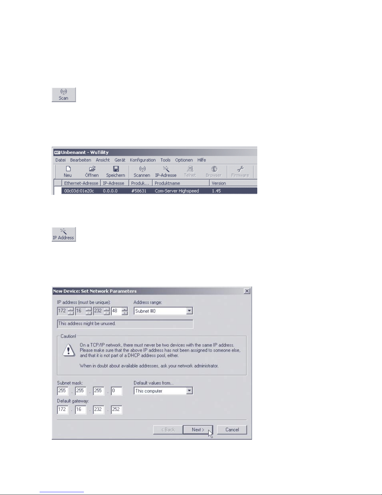
Within the inventory list you can identify the desired Com-Server based on its MAC address. For initial installations its IP
address is 0.0.0.0.
Select the Com-Server and click on the IP address button:
Enter the desired values for IP address, subnet mask and
gateway address in the corresponding fields and then click on
the Next button.
16
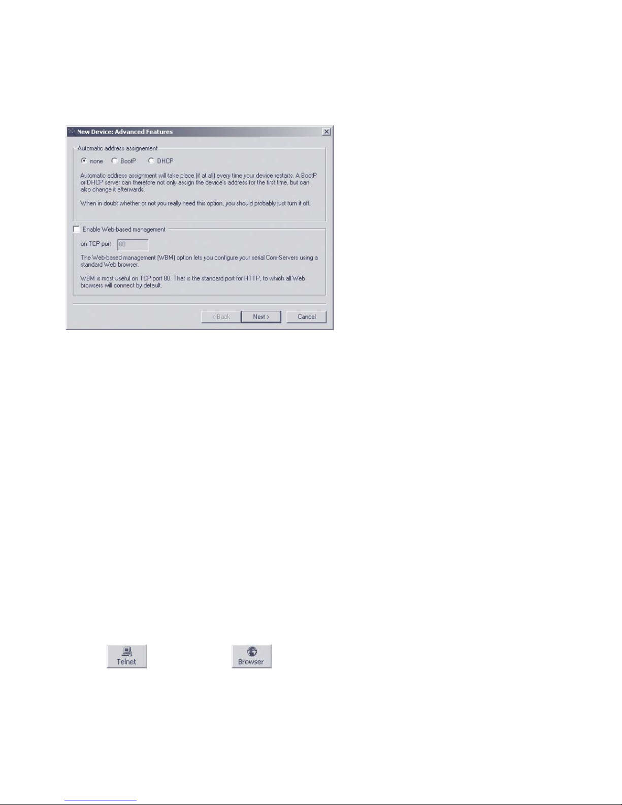
W&T Assigning the IP address
In the following window you can activate the BOOTP client and
the Web-Based-Management of the Com-Server.
1
To prevent unintended address assignments or changes,
we recommend deactivating the DHCP, BOOTP and RARP
protocols if they are not expressly used in the respective
network environment. Com-Servers with incorrectly assigned IP
addresses can be easily found after the fact using the scan
function of the WuTility management tool and reconfigured.
Clicking on the Next button assigns the network parameters to
the Com-Server. All columns in the WuTility device list are filled
with information.
This concludes the network-side startup of the Com-Server, and
for many applications – such as use together with the COM Port
Redirector – no further settings are necessary. Special modes
or serial parameters can be set using the telnet configuration
menu or, if Web-Based-Management was used, with the help of
the Internet browser. To do this, click on either the Telnet or
Browser button:
Telnet:
Browser:

17
W&T Assigning the IP address
Subject to error and alteration
1
Changing network parameters is protected by the
system password. To prevent improper access, we
recommend assigning a system password for any Com-Servers
in use.
Additional information can be found in the section
Configuration Accesses for the Com-Server.

18
W&T Assigning the IP address
2.2 Assigning the IP using the ARP command
1
This method can only be used if the Com-Server
does not already have an IP address, i.e. the entry is
0.0.0.0. To change an IP address, use one of the other
methods described in this section or use the configuration
menu over Telnet.
Required is a computer which is located in the same network
segment as the Com-Server and which has TCP/IP protocol
installed. Read off the Ethernet address of the Com-Server
from the sticker on the side of the housing:
58xxx [Model]
EN=00c03d004a05
OK xxxxxx
Ethernet address
Insert a static entry into the ARP table of the computer using
the following command line:
arp -s [IP address] [MAC address]
e.g. under Windows:
arp -s 172.16.231.10 00-C0-3D-00-12-FF
e.g. under SCO UNIX:
arp -s 172.16.231.10 00:C0:3D:00:12:FF
Next use the following command line under Start r Run to
start a Telnet session on the configuration port of the ComServer with the desired IP address:
telnet 172.16.232.10 1111 [
Return
]
1
The IP addresses must be without leading zeros in
all Windows environments. Otherwise the entry is
incorrectly interpreted by the system and an incorrect IP
address is assigned to the Com-Server.
i
The IP address must
be unique within the
network.
i
Older Windows systems
only accept a static
entry if there is a
dynamic one already
present. Here you
should first ping
another network
station.

19
W&T Assigning the IP address
Subject to error and alteration
The Com-Server takes the IP address of the first network packet
sent to it as its own and saves it in non-volatile memory. The
Telnet connection will be established and the configuration
menu is displayed in the Telnet window. All further settings are
made here (see Basic configuration of the Com-Server).

20
W&T Assigning the IP address
2.3 Serial assigning of IP, subnet mask and gateway
After a Com-Server reset a time window of around 1-2
seconds is available, during which you can assign a new IP
address, subnet mask and gateway address by entering at
least 3 „x“.
1
In contrast to the ARP method described above, this
serial method functions regardless of whether the
Com-Server already has an IP address or not. The procedure
can be repeated as often as desired. Therefore use this
method if you don‘t know the IP address or have forgotten it.
Appendix D contains the detailed procedure under Windows
using HyperTerminal.
First connect the serial port A of the Com-Server to a
computer. For a standard PC or laptop, you will need a
crossed RS232 cable (=Null modem cable, see RS232
interface).
The serial transmission parameters of the terminal program
you use should be set to 9600 baud, no parity, 8 bits, 1 stop
bit, no handshake. Reset the Com-Server by interrupting the
power. When the green status LED lights up, enter the letter
„x“ at least three times on the terminal, until the Com-Server
returns the prompt IPno.+<Enter>.
Use the usual format (xxx.xxx.xxx.xxx) to enter the IP
address, and end the entry by pressing <Enter>. If the entry
was accepted, the acknowledgement is the assigned IP
address. Otherwise you will get a FAIL message followed by
the last current IP address.
All other settings such as gateway address, subnet mask etc.
are done through the Telnet configuration menu (see Basic
configuration of the Com-Server).

21
W&T Assigning the IP address
Subject to error and alteration
2.3.1 Assigning of subnet mask and gateway address
Together with the IP address, the subnet mask and gateway
address can also be assigned serially. The entry is separated
by commas and follows the IP address. Entering as shown in
the following example will assign IP address 172.17.231.99,
subnet mask 255.255.255.0 and gateway 172.17.231.52 to
the Com-Server
IP no.+<ENTER>: <- Com-Server
172.17.231.99,255.255.255.0,172.17.231.52 -> Com-Server
172.17.231.99,255.255.255.0,172.17.231.52-1 <- Com-Server
2.3.2 Deactivating DHCP/BOOTP/RARP
The DHCP/BOOTP/RARP function of the Com Server can be
turned off as part of assigning the IP address serially. We
recommend making use of this at all times except where use
of DHCP, BOOTP or RARP is expressly required. To deactivate
the DHCP/BOOTP/RARP client enter the option „-0“ (zero)
directly appended (no space!) to the IP address and confirm
with <Enter>.
• -0
DHCP, BOOTP and RARP = OFF
• -1
DHCP = OFF,
BOOTP and RARP = ON
• -2
DHCP = ON
BOOTP and RARP = OFF
Example: Deactivation of DHCP, BOOTP and RARP
xxx - > Com-Server
IP no.+<ENTER>: <- Com-Server
172.17.231.99-0 - > Com-Server
172.17.231.99 <- Com-Server
i
An explanation of the
basic terms and
concepts for
addressing in the
internet and using
DHCP and BOOTP can
be found in our
manual TCP/IP-
Ethernet and Web-IO.

22
W&T Assigning the IP address
This function can later be reactivated through the Telnet
configuration under SETUP System r SETP TCP/IP r BOOTP
Client.
1
To prevent unintended address assignments or changes,
we recommend deactivating the DHCP, BOOTP and RARP
protocols if they are not expressly used in the respective
network environment. Com-Servers with incorrectly assigned IP
addresses can be easily found after the fact using the scan
function of the WuTility management tool and reconfigured.
2.3.3 Serial activation of Web Based Management
To further configure the Com-Server you can use either Telnet
protocol or an Internet browser, although only Telnet is an
option in the Com-Server as shipped from the factory. You can
activate Web Based Management as part of the serial IP
assignment. To do this, enter +w[Portno.] directly after the IP
address or address string. Here Portno. is the desired TCP port
in decimal format.
Example 1: Deactivating DHCP/BOOTP/RARP and activating Web
Based Management on TCP port 8080.
xxx - > Com-Server
IP no.+<ENTER>: <- Com-Server
172.17.231.99,255.255.0.0,172.17.231.52-0+w8080 -> Com-Server
172.17.231.99,255.255.0.0,172.17.231.52-0+w8080 <- Com-Server
Example 2: Activation of Web Based Management on TCP port
80. The status of DHCP/BOOTP/RARP remains unchanged.
xxx - > Com-Server
IP no.+<ENTER>: <- Com-Server
172.17.231.99+w80 -> Com-Server
172.17.231.99- 1 < - Com-Server

23
W&T Assigning the IP address
Subject to error and alteration
1
For additional information on activating Web Based
Management, see section Configuration via Browser
Web Based Management.

24
W&T Assigning the IP address
2.4 Assigning the IP using DHCP protocol
Many networks use DHCP (Dynamic Host Configuration
Protocol) or its predecessor described in the following section
for centralized and dynamic assignment of the network
parameters. DHCP protocol is activated by the factory default
settings, so that in network environments dynamic IP
assignment is sufficient for connecting the Com-Server to the
network. The following parameters can be assigned using
DHCP:
• IP address
• Subnet mask
• Gateway address
• DNS server
• Lease time
1
To prevent unintended address assignments or changes,
we recommend deactivating the DHCP, BOOTP and RARP
protocols if they are not expressly used in the respective
network environment. Com-Servers with incorrectly assigned IP
addresses can be easily found after the fact using the scan
function of the WuTility management tool and reconfigured.
2.4.1 Activating/Deactivating DHCP
The factory default setting is for DHCP protocol active. To
deactivate it or to enable it again later, use one of the following
options.
• Management-Tool WuTility
Select the desired Com-Server in the device list and click on the
IP Address button. In the first dialog box enter the newly
assigned network parameters and then click on Continue. In the
following dialog BOX deactivate the options BOOTP and DHCP.

25
W&T Assigning the IP address
Subject to error and alteration
Clicking on Continue then sends the new configuration data to
the Com-Server.
• Serial port
As part of serial IP assignment, the following options for
deactivating/activating DHCP and BOOTP can be selected
directly following the address string:
-0 r Deactivates DHCP and BOOTP
-1 r Activates BOOTP/RARP
-2 r Activates DHCP
A detailed description of the procedure can be found in the
section on Serial assignment of IP, subnet mask and gateway.
• Telnet or Web Based Management
From the menu branch SETUP System r Setup TCP/IP r DHCP/
BOOTP Client the protocols can be alternately activated and
both deactivated. For detailed information refer to the section
Menu: SETUP System.
2.4.2 System Name
To support any automatic updating of the DNS system by the
DHCP server, the Com-Server identifies itself within the DHCP
protocol with its system name. The factory default setting for
this is COMSERVER_ followed by the last three places of the
Ethernet address. For example the factory set system name of
a Com-Server with the Ethernet address 00:c0:3d:01:02:03 is
COMSERVER_010203. The system name of the Com-Server can
be changed in the configuration. For additional information
refer to the section Menu: SETUP System r System Name.

26
W&T Assigning the IP address
2.4.3 Lease-Time
The lease time determined and transmitted by the DHCP server
specifies the Time-To-Live of the assigned IP address. After half
the lease time has expired, the Com-Server attempts to extend
the time for the assigned DHCP server and up update the
address. If this is not possible by the time the lease time
expires, for example because the DHCP server can no longer
be reached, the Com-Server deletes the IP address and starts a
new cyclical search for alternate DHCP servers for the purpose
of assigning a new IP address.
Because of the absent clock, the lease time associated with the
current IP address is no longer available after a reset. After the
restart therefore a corresponding update request is issued with
the original DHCP server. If the latter is not resolvable at this
point in time, the Com-Server deletes the IP address and starts
a new cyclical search for alternate DHCP servers.
If DHCP is activated, the remaining lease time together with the
current IP address is displayed in the menu item SETUP System
r Setup TCP/IP r IP-Address using the format hh:mm:ss.
1
If after the assigned lease time has expired the DHCP
server is not reachable, the Com-Server deletes its IP
address. All existing TCP/UDP connections between the ComServer and other network clients are thereby closed. To prevent
such events, we recommend configuring the assigned lease
time in the DHCP server to infinite if possible.

27
W&T Assigning the IP address
Subject to error and alteration
2.4.4 Reserved IP addresses
If the Com-Server is used as a TCP server or UDP peer, it
provides services which other clients in the network can also
make use of as needed. To open a connection, they of course
need the current IP address for the Com-Server, so that in such
situations it makes sense to reserve a particular IP address for
the Com-Server on the DHCP server. This is generally done by
linking the IP address to the unique Ethernet address of the
Com-Server, which can be found on the sticker attached to the
housing.
58xxx [Typ]
EN=00c03d004a05
OK xxxxxx
Ethernet-Adresse
2.4.5 Dynamic IP addresses
Fully dynamic address assignment, whereby the Com-Server
gets a different IP address every time it is restarted or after the
lease time has expired, only makes sense in network
environments with automatic cross-connection between the
DHCP and DNS services. This means when a new IP address is
assigned to the Com-Server, the DHCP server then
automatically updates the DNS system as well. The new address
is associated with the respective domain name. If in doubt,
consult your system administrator for detailed information
about your network environment.
If the Com-Server is configured as a TCP or UDP client and itself
actively searches for a connection to server services in your
network, dynamic changing IP addresses may be used.

28
W&T Assigning the IP address
2.5 Assigning the IP using BOOTP protocol
Many networks use BOOTP as predecessor of DHCP protocol
for centralized and dynamic assignment of IP addresses. The
factory default setting is for BOOTP turned off. You can activate
it from SETUP System r SETUP TCP/IP r BOOTP Client. The
following parameters can be assigned:
• IP address
• Subnet mask
• Gateway address
• DNS server
1
To prevent unintended address assignments or changes,
we recommend deactivating the DHCP, BOOTP and RARP
protocols if they are not expressly used in the respective
network environment. Com-Servers with incorrectly assigned IP
addresses can be easily found after the fact using the scan
function of the WuTility management tool and reconfigured.
2.5.1 Address reservation
BOOTP protocol is based on fixed reservations of fixed IP
addresses for particular Ethernet addresses. This means a ComServer connected to the network only gets an IP address if the
latter was previously stored in the BOOTP server. Check with
your system administrator for creating this reservation. The
Ethernet address of the Com-Server can be found on the
housing sticker.
58xxx [Model]
EN=00c03d004a05
OK xxxxxx
Ethernet address
Once the administrator has made the necessary entries, the
Com-Server obtains the desired IP address automatically after

29
W&T Assigning the IP address
Subject to error and alteration
each reset. To ensure accessibility of the Com-Server even
should the BOOTP server go down, the previous IP address is
retained should there be no reply.

30
W&T Assigning the IP address
2.6 Assigning the IP using a RARP server
UNIX environments especially use RARP protocol for centrally
assigning IP addresses. TCP/IP devices that want to obtain an
IP address send RARP requests with their Ethernet address as a
broadcast over the network.
RARP protocol is coupled to BOOTP protocol in the Com-Server. Activate it from SETUP System r SETUP TCP/IP r BOOTP
Client.
Activate the RARP server, and enter the Ethernet address of the
Com-Server in the file /etc/ethers and the IP address in the file
/etc/hosts.
58xxx [Model]
EN=00c03d004a05
OK xxxxxx
Ethernet address
The Com-Server must be connected to the network in the same
segment as the RARP server.
Example:
Your Com-Server has the MAC address EN= 00C03D0012FF
(sticker on the unit). You want to give it IP address
172.16.231.10 and the alias name WT_1:
• Entry in the file /etc/hosts:
172.16.231.10WT_1
• Entry in the file /etc/ethers:
00:C0:3D:00:12:FF WT_1
1
To prevent unintended address assignments or changes,
we recommend deactivating the DHCP, BOOTP and RARP
protocols if they are not expressly used in the respective
network environment. Com-Servers with incorrectly assigned IP
addresses can be easily found after the fact using the scan
function of the WuTility management tool and reconfigured.
 Loading...