

Page 1

Manual
Web-IO 12+12 Digital
Release2.07, November 2004
Type 57630, 57631
ModelFirmware 1.42/2.07 and higher
W&T
Page 2

W&T
© 12/2003 by Wiesemann und Theis GmbH
Microsoft, MS-DOS, Windows, Winsock and Visual Basic
are registered trademarks of Microsoft Corporation
Subject to error and alteration:
Since it is possible that we make mistakes, you mustn't use any of our statements
without verification. Please, inform us of any error or misunderstanding you come
about, so we can identify and eliminate it as soon as possible.
Carry out your work on or with W&T products only to the extent that they are
described here and after you have completely read and understood the manual or
guide. We are not liable for unauthorized repairs or tampering. When in doubt, check
first with us or with your dealer.
Page 3

W&T
Introduction
The W&T Web-IO provides the ability to monitor and set 12 digital inputs and 12 digital outputs using Ethernet TCP/IP.
The digital inputs are galvanically isolated in groups of 4 each and
can be driven with +/- 30V.
The outputs are current sourcing and can be fed with 6 - 30V
thorugh a common voltage input. UP to 500mA per output can
be switched. The individual outputs have thermal overload
protection and are short circuit protected. The outputs can be
wired in pairs or in parallel in groups of 4 outputs each to
achieve higher switching currents.
The Ethernet interface is configured as 10/100Mbit
autosensing.
The following TCP/IP protocols are available for reading and
setting the in- and outputs:
HTTP Simple user interface in the browser window
TCP Direct socket access from your own applications
UDP Direct socket access from your own applications
SMTP Alarm triggering via e-mail with configurable input
conditions
SNMP Incorporation into management systems and
alarm triggering via SNMP trap
Box-to-Box
Paired linking of Web-IOs
Configuration of the Web-IO can be performed via Web-Based
Management manually in the browser window or loaded using
an XML file.
The 12X Digital Web-IO can be powered with 12-24V AC or DC
connected to screw terminals. Alternately the included plug-in
power supply can be used for 230V operation.
Page 4

4
W&T Content
Content
Introduction 3
1 Before starting up 9
1.1 Supply voltage and network connection 10
2 Assigning the IP address 11
2.1 Assigning the IP address using the WuTility-Tool 12
2.2 Assigning the IP address using the ARP command 14
2.3 Assigning the IP address through the serial port 16
2.3.1 Serial assignment of subnet mask and gateway 16
2.3.2 Serial deactivation of the DHCP-/BOOTP client 17
2.4 IP assignment via RARP server 18
2.5 IP assignment via DHCP-/BOOTP protocol 19
2.5.1 Deactivating the DHCP/BOOTP protocol 20
3 Connections, operating elements and LEDs 23
3.1 Overview of connections and elements 24
3.2 Ethernet connection 25
3.3 Serial connection 26
3.4 Supply voltage input 27
3.5 LEDs for device status 28
3.6 Input- and Output connections 30
3.6.1 Input circuit 30
3.6.2 Output circuit 31
4 Configuring the network parameters 33
4.1 Web-Based Management 34
4.1.1 Basics 34
4.1.2 Structure of the Web site 34
4.1.3 Navigation 34
4.1.4 Easier navigation with profiles 36
4.1.5 Access rights 36
4.1.6 Changing and creating the access passwords 38
4.1.7 Saving and activating settings 38
4.2 Basic setting of the network parameters 40
5 Access types 45
5.1 Possible operating modes - An overview 46
5.1.1 Basic operating modes 46
Page 5

5
W&T Content
Subject to errors and modifications:
5.1.2 Alarm service 49
5.1.3 Input /Output service 49
5.1.4 System Service 50
5.2 Specifying the output mode 51
5.3 HTTP - In- and Output control from the browser 52
5.3.1 Labeling and texts 53
5.3.2 Creating your own Web site for the Web-IO 57
5.3.3 Java Applets - Auto-updating in the browser 64
Working with the Java applet 64
Using the applet with JavaScript 67
Limits when using the Java applet 71
5.4 Controlling the Web-IO with TCP/UDP Sockets 72
5.4.1 Selecting the appropriate access mode 72
5.5 Socket programming with command strings 75
5.5.1 TCP communication 75
5.5.2 UDP communication 81
5.5.3 Program-controlled error management 85
5.6 BINARY - socket programs with binary structures 91
5.6.1 Specifying the operation mode 92
5.6.2 The Web-IO as socket server 93
5.6.3 The Web-IO as socket client 94
5.6.4 The Web-IO as UDP Peer 97
5.6.5 Passwort protection 100
5.6.6 BINARY - The IO structures 102
5.6.7 Definition of the IO structures 103
5.6.8 Working with the IO structures 104
5.6.9 IO structures in various languages 109
5.7 Box-to-Box 116
5.7.1 Configuring theSlave Web-IO 116
5.7.2 Configuring the master 119
5.7.3 GetBox-to-Box connection status 124
5.7.4 Stopping Box-to-Box mode 124
5.7.6 Box-to-Box notes and limitations 126
5.8 OPC - standardized access 128
5.8.1 Installing the OPC-Server 128
5.8.2 Uninstalling 129
5.8.3 Configuration 129
5.8.4 Configuring the Web-IO as an OPC device 132
5.8.5 Program options 134
5.8.6 Direct control from control panels 136
Abbreviations used 136
Page 6

6
W&T Content
5.8.7 Access using Visual Basic or VBA 137
5.8.8 One Web-IO, multiple client computers 140
5.9 SNMP - In-/Outputs in management systems 142
5.9.1 Enabling SNMP access 142
5.9.2 Activating the outputs for SNMP 143
5.9.3 Main steps for SNMP access 144
5.10 Syslog - Get system messages 146
5.10.1 Enable Syslog 146
5.11 Alarms 148
5.11.1 Specifying alarm conditions 148
5.11.2 E-Mail-Alarm - SMTP 151
5.11.3 SNMP Alarm 154
5.11.4 Alarm via UDP 156
5.11.5 Alarm message to your own TCP applications 157
5.11.6 Alarm message to a TCP server 158
5.11.7 Sending alarm messages to a Syslog-Server 160
5.11.8 General information about alarms 162
6 General Functions 163
6.1 Time / Date - Setting 164
6.1.1 Time zones 164
6.1.2 Summer time / Winter time 165
6.1.3 Start and end of summer time 165
6.1.4 End of summer time 166
6.1.5 Time-Server 167
6.1.6 Manually setting time and Date 169
6.1.7 Activating all time/date settings 170
6.2 Safety Timeout / State - Access monitoring 171
6.2.1 Specifying safety timeout 171
6.2.2 Safety State festlegen 172
6.3 Ports - Input- and output configuration 174
6.3.1 Input configuration 174
6.3.2 Output configuration 175
6.4.3 Logic functions 178
6.3.4 Pulse mode 180
6.5 Changing device-specific displays 182
6.6 Upload/Download 184
6.6.1 Download 184
6.6.2 Upload 185
6.7 Diagnostics and testing 187
6.7.1 Error report 187
Page 7

7
W&T Content
Subject to errors and modifications:
6.7.2 Configuration 188
6.7.3 LED test 192
7 Appendix 195
7.1 Firmware Update 196
7.1.1 Where can I get the current firmware? 196
7.1.2 Firmware update over the network using WIndows 196
7.2 Emergency access 198
7.3 Ports and network security 199
7.3.1 Ports 199
7.3.2 The W&T Web-IO and network security 199
7.3.4 Ports mit special function: 201
7.4 Network inventory via UDP 203
7.4.1 The info packet 203
7.5 Wiring examples for the inputs 206
7.6 Wiring examples for the outputs 207
7.7 Error messages and causes 208
7.7 Technical Data 210
7.9 Declaration of Conformity 211
Page 8

8
W&T Content
Page 9

9
W&T Befor starting up
1 Before starting up
We recommend to read the complete Manual for the 12+12 Digital Web-IO before startup.
. Connecting the supply voltage
. Connecting to the network
Page 10
10
W&T Befor starting up
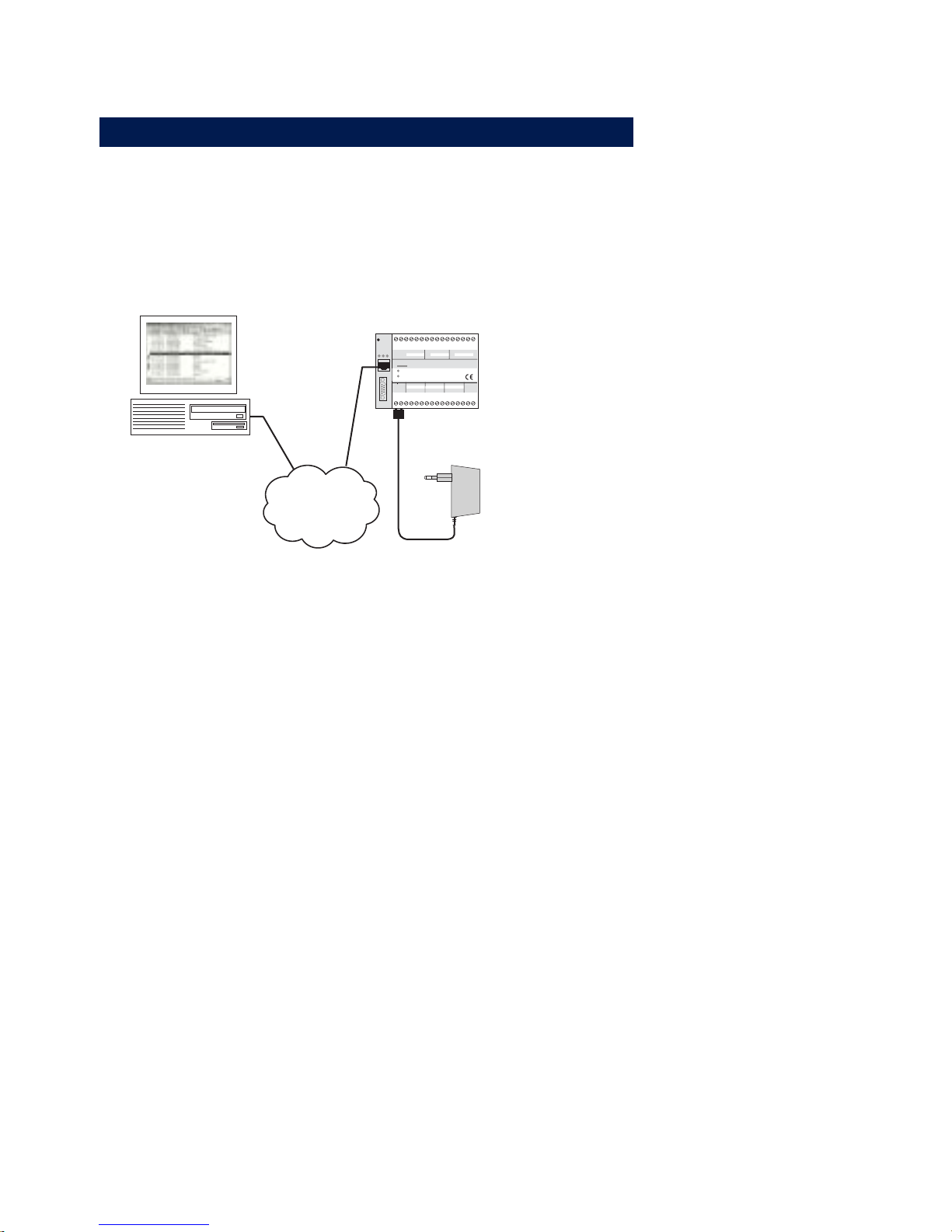
1.1 Supply voltage and network connection
Use a patch cable to connect the Web-IO to an unused HUB or
SWITCH port. The Web-IO has an autosensing 10/100BaseT
network connection and automatically detects the network
speed.
Internet/
Intranet
1
23
4
5678
9
10 11 12 13
14 15
16
17 18 19
20 21 22 23 24 25 26 28 29 30
31
32
27
Reset
Power
Status
Error
Serial Port
on
error
system error
http:// . . . /diag
0 11109GND 87546321GND
GND
GND
INPUT GROUP 0 INPUT GROUP 1 INPUT GROUP 2
0
11109
GND
87546321Vcc
6-30V DC
+Vdd
OUTPUT GROUP 0 OUTPUT GROUP 1
OUTPUT GROUP 212-24V
Vcc
W&T
www.wut.de
Web-IO #57630
12xDigital-IO <-> 10/100BT
Connect a supply voltage of between 12 V and 24 V AC or DC
to terminals 1 and 2.
Compatible power supplies can be obtained as an accessory
from W&T. See http://www.wut.de Products & Downloads >>
Web-IO Digital.
After approx. 2 sec. a beep will sound and the Status and Error
LEDs should have turned off. If the red Error LED flashes, check
the network connection.
1
If the WEB-IO has no IP address or address 0.0.0.0, the
on error and system error LEDs remain on after a reset
or new start! The LEDs will turn off only if an IP address has
been assigned.
Page 11

11
W&T Assigning the IP address
Subject to errors and modifications:
2 Assigning the IP address
The Web-IO is factory set to IP address 0.0.0.0. Before assigning a new one,
you must obtain an appropriate IP address from your system administrator.
In smaller, unrouted networks use the IP address of your PC and simply
change the last digit.
1 Always bear in mind that IP addresses must be unique within a network.
. Assigning using the WuTility tool
. Assigning using the ARP command
. Assigning through the serial port
. Assigning via RARP protocol
. Assigning via DHCP/BOOTP protocol
Page 12
12
W&T Assigning the IP address
2.1 Assigning the IP address using the WuTility-Tool
1
This method cannot be used if you do not have a PC
running under Windows and an installed TCP/IP stack.
In this case, skip to section 2.2.
The other requirements are that the Web-IO does not yet have
an IP address, i.e., the address is 0.0.0.0, and the PC is located
in the same network segment as the Web-IO.
If the Web-IO already has an IP address, change it by using one
of the other methods described in this section of by using the menu
item Config/Device/Network in the Web-based Management of the
Web-IO.
First start WuTility.exe from any desired directory on your hard
drive.
g
On our web site www.WuT.de, having selected the
Englisch language version, on the left side you find „Insider search via article number“. Enter here the article no.
57630, select „Tools“ in the checkbox below and click „Go“. On
the page that will open, you select the link „WuTility“.
Click on the
icon to start the network scan.
The list of found W&T network components should now contain
an entry for the Web-IO. The IP address should be indicated as
0.0.0.0 if you are starting up for the first time. Check the
Page 13

13
W&T Assigning the IP address
Subject to errors and modifications:
displayed Ethernet address to make sure the entry agrees with
your Web-IO.
Read off the Ethernet address of the Web-IO from the sticker on
the side of the housing:
5763x [Model]
EN=00c03d003fa0
OK xxxxxx
Ethernet address
Select the entry for your Web-IO.
Click on the
icon and enter the IP address you want to assign
to the Web-IO.
Click on the
icon to update the list.
Now your Web-IO has an IP address and can be accessed in the
local network.
All other settings can now be easily made via Web-Based
Management (see section Basic setting of network parameters)
Page 14

14
W&T Assigning the IP address
2.2 Assigning the IP address using the ARP command
1
This method can only be used if the Web-IO does not yet
have an IP address, i.e., if the entry is 0.0.0.0. To change
an IP address, use one of the other methods described in this
section or use the menu item Config/Device/Network in the WebBased Management of the Web-IO.
An additional prerequisite is a computer which is located in the
same network segment as the Web-IO and on which TCP/IP
protocol is installed. Read off the Ethernet address of the Web-IO
from the sticker on the side of the housing:
5763x [Model]
EN=00c03d003fa0
OK xxxxxx
Ethernet address
Now use the following command to add a static entry to the
ARP table of your PC :
arp -s [IP address] [MAC address]
Example under Windows:
arp -s 172.16.231.17 00-C0-3D-00-3F-A0
Example under SCO UNIX:
arp -s 172.16.231.17 00:C0:3D:00:3F:A0
i
Older Windows systems accept a static entry only if a
dynamic entry already exists. Here you should first ping
another network station.
Finally start the Web browser and enter the following URL:
http://[IP address]
[
Return
]
Example:
Page 15

15
W&T Assigning the IP address
Subject to errors and modifications:
1
In Windows environments IP addresses must be entered
without leading zeroes. Otherwise the system interprets
the entry incorrectly and an incorrect IP address is assigned to
the Web-IO.
The Web-IO takes the IP address of the first network packet sent
to its Ethernet address as its own and saves it in non-volatile
memory. The HTTP connection is then opened and the
Homepage of the Web-IO appears in the browser. All other
settings can now be easily made via Web-Based Management
(see section Basic setting of the network parameters).
Page 16

16
W&T Assigning the IP address
2.3 Assigning the IP address through the serial port
After a reset of the Web-IO a time window of approx. 1-2
seconds is made available, during which entering at least 3 „x“
makes it possible to assign a new IP address.
1
In contrast to the previously described method via
ARP, the serial way works regardless of whether the WebIO already has an IP address or not. The procedure may be
repeated as often as desired. Therefore you should use this
method if you don‘t know the IP address or have forgotten it.
The appendix to this manual contains a detailed description for
using Windows with Hyperterminal.
First connect the Web-IO to the serial port of a computer. For a
standard PC a crossed RS232 cable (= null modem cable) is
required (see section Serial connection).
The serial transmission parameters of the terminal program used
are configured for 9600 baud, no parity, 8 bits, 1 stop bit, no
handshake. Press the reset button on the Web-IO briefly and enter
the letter „x“ at least three times on the terminal until the prompt
IPno.+<Enter>: appears in the terminal program.
Use the conventional format (xxx.xxx.xxx.xxx) to enter the IP
address, and finish your entry with <Enter>. If the entry was
accepted, the system acknowledges with the assigned IP address.
Otherwise a FAIL message is issued followed by the last current
IP address.
All additional settings can now be made easily via Web-Based
Management in the browser (see section Basic setting of the
network parameters).
2.3.1 Serial assignment of subnet mask and gateway
Together with the IP address, the subnet mask and gateway
address can also be assigned serially. The entry is comma
delineated following the IP address. The following example
Page 17

17
W&T Assigning the IP address
Subject to errors and modifications:
assigns IP address 172.17.232.17, subnet mask 255.255.255.0
and gateway 172.17.232.252 to the Web-IO.
IP no.+<ENTER>: <- Web-IO
172.17.232.17,255.255.255.0,172.17.232.252 -> Web-IO
172.17.232.17,255.255.255.0,172.17.232.252-1 <- Web-IO
2.3.2 Serial deactivation of the DHCP-/BOOTP client
The DHCP-/BOOTP function of the Web-IO can be turned off
while serially assigning the IP address. We recommend doing
this in any case where the IP assignment will not be expressly
performed using DHCP/BOOTP.
To deactivate the DHCP/BOOTP client, enter the option „-0“
(zero) immediately following the IP address (no spaces!) and
finish the entry with <Enter>.
Example:
xxx -> Web-IO
IP no.+<ENTER>: <- Web-IO
172.17.232.17,255.255.255.0,172.17.232.252-0 -> Web-IO
172.17.232.17,255.255.255.0,172.17.232.252-0 <- Web-IO
This of course functions the same way when entering the
subnet mask and gateway..
You can reactivate the function at any time later by using WebBased Management im the browser.
Menu item: Config >> Device >> Network
Page 18

18
W&T Assigning the IP address
2.4 IP assignment via RARP server
UNIX environments especially often use RARP protocol for
centrally assigning IP addresses. Here TCP/IP devices that want
an IP address send RARP requests with your Ethernet address as
a network broadcast.
Activate the RARP server on the UNIX system and enter the
Ethernet address of the Web-IO in the file /etc/ethers. You must
also enter the IP address of the Web-IO in the file /etc/hosts.
5763x [Model]
EN=00c03d003fa0
OK xxxxxx
Ethernet address
The Web-IO must be located in the same subnet as the RARP
server.
Example
Your Web-IO has the MAC address EN= 00C03D003FA0 (device
sticker). You want to give it the IP address 172.16.232.17 and the
alias name WEBIO_1:
• Entry in the file /etc/hosts:
172.16.232.17 WEBIO_1
• Entry in the file /etc/ethers:
00:C0:3D:00:3F:A0 WEBIO_1
If the Web-IO‘s IP address is 0.0.0.0 (=Factory Default), RARP
broadcasts are cyclically generated in order to obtain a valid
address from any existing RARP daemon.
If the Web-IO already has a valid IP address, an RARP broadcast
is generated following each reset. If a reply follows within 500ms,
the IP address contained therein is accepted. As with assigning via
the serial port, this method also makes it possible to overwrite a
current IP address.
Page 19

19
W&T Assigning the IP address
Subject to errors and modifications:
2.5 IP assignment via DHCP-/BOOTP protocol
Many networks use DHCP (Dynamic Host Configuration
Protocol) or BOOTP for central and dynamic assignment of IP
addresses. Which of these two protocols should be used in
connection with the Web-IO makes no difference, since DHCP
is simply a backwards compatible extension of BOOTP. DHCP
servers thus also handle requests from BOOTP clients. The
following parameters can be assigned to the Web-IO using
these protocols:
. IP address
. Subnet mask
. Gateway address
It is not possible to send additional parameters or lease-time.
Function
To obtain an IP address, the Web-IO sends a corresponding
BOOTP request as a broadast to the network following each new
start. The resulting reply generated by the DHCP/BOOTP server
contains in addition to the IP address the subnet mask and
gateway address as well. The Web-IO immediately places this
information in its non-volatile memory.
To start up the Web-IO in DHCP/BOOTP networks, contact your
system administrator. If DHCP is used to assign the address,
please indicate that a reserved IP address is needed. To
maintain the respective address database, the administrator will
need the Ethernet address of the Web-IO, which can be found
on the sticker on the housing:
5763x [Model]
EN=00c03d003fa0
OK xxxxxx
Ethernet address
After the administrator has made the necessary settings, the WebIO automatically gets the desired IP address after each reset. To
ensure that the Web-IO can be reached even if the DHCP/BOOTP
Page 20

20
W&T Assigning the IP address
server is down, the previous IP address is maintained if there is
no reply.
1
In DHCP environments the IP address to be
assigned must be reserved by a fixed entry in the DHCP
table with the Ethernet address of the Web-IO. Under WIndows
NT this is done in the DHCP manager under the menu item
„Reservations“. Linux provides the file „dhcpd.conf“ for this
purpose, in which a corresponding entry must be made.
2.5.1 Deactivating the DHCP/BOOTP protocol
A DHCP server assigns IP address dynamically from an address
pool assigned by the administrator. This means that DHCP-capable
devices usually get another IP address after each start. Since a
constantly changing IP address is not desired with the Web-IO, the
latter uses the BOOTP protocol based on fixed relationships
between Ethernet and IP address. DHCP servers should reply to
BOOTP requests only if they use explicit IP reservation for the
Ethernet address of the sender.
Some DHCP servers (e.g., Windows 2000 servers) however serve
both DHCP as well as BOOTP requests from their dynamic
address pool. To prevent the Web-IO from getting IP addresses
unknown to the user assigned in such environments, the
following options are available:
. Before connecting the Web-IO to the network, you must
make a reservation in the respective DHCP server.
. The IP address of the Web-IO is assigned through the serial
port. Sending „xxx“ to the Web-IO during a new start takes you
to the input mode for a new IP address. Enter it followed by
the string „-0“ (zero) to deactivate the BOOTP client of the
Web-IO (see section IP assignment through the serial port).
Page 21

21
W&T Assigning the IP address
Subject to errors and modifications:
In existing systems the BOOTP client of the Web-IO can also be
activated and deactivated at any time using Web-Based Management in the browser.
Menu item Config >> Device >> Network
Page 22

22
W&T Assigning the IP address
Page 23

23
W&T Connections, operating elements and LEDs
Subject to errors and modifications:
3 Connections, operating elements and LEDs
. Ethernet connection
. RS232
. Supply voltage connection
. Reset button
. Device status LEDs
. Input and Output connections and LEDs
Page 24
24
W&T Connections, operating elements and LEDs
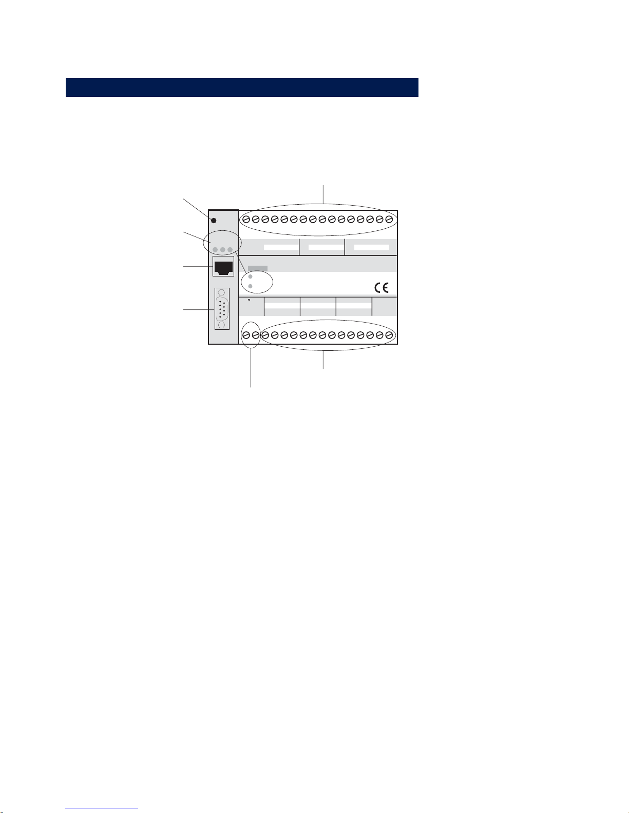
3.1 Overview of connections and elements
on
error
system error
http:// . . . /diag
0 11109GND 87546321GND
GND
GND
INPUT GROUP 0 INPUT GROUP 1 INPUT GROUP 2
0
11109
GND
87546321Vcc
6-30V DC
+Vdd
OUTPUT GROUP 0 OUTPUT GROUP 1
OUTPUT GROUP 212-24V
Vcc
W&T
www.wut.de
Web-IO #57630
12xDigital-IO <-> 10/100BT
1
23
4
5678
9
10 11 12 13
14 15
16
17 18 19
20 21 22 23 24 25 26 28 29 30
31
32
27
Reset
Power
Status
Error
Serial Port
Reset
Device State
LEDs
RS232
Port
Supply Voltage Input
Outputs
Inputs
Ethernet
Page 25

25
W&T Connections, operating elements and LEDs
Subject to errors and modifications:
3.2 Ethernet connection
The Web-IO models provide an IEEE 802.3-compatible network
connection via a shielded RJ45 connector. The pinouts correspond
to an MDI interface, so that the connection to the hub or switch
can be made with a 1:1 shielded patch cable.
1 = Tx+
2 = Tx-
3 = Rx+
4 = nc 5 = nc
6 = Rx-
7 = nc
8 = nc
RJ45-Buchse (Belegung AT&T256)
10/100BaseT, Autosensing
Both 10BaseT and 100BaseTx standard with a bit rate of
100MBit/s and the possibility of full-duplex transmission are
supported. Changing between the two network speeds is
automatically done by the autosensing function of the Web-IO
depending on the possibilities of the hub or switch used. The
prerequisite for operation at 100MBit/s is suitable cabling (at
least conforming to Cat. 5/ISO Class D).
Galvanic isolation
The network connection is galvanically isolated with respect to the
supply voltage and to the digital IOs and the serial port(s) up to at
least 500V
rms
.
Link status
The Error LED on the front of the unit indicates the current link
status: If it flashes at 1-2 second intervals, there is no
connection to the hub or the connection is faulty.
Page 26

26
W&T Connections, operating elements and LEDs
3.3 Serial connection
On the Web-IO 12+12 Digital type 5730 the serial port is
provided only for configuration purposes, such as assigning
the IP address. With Type 57631 it also enables funktioality of
a serial Com-Server.
The pinouts of this RS232 port are identical to those of your
PC. This lets you use standard cables.
A detailed pin description as well as the W&T cables required for
most common applications can be found in the illustrations below.
RS232 pin assignments and functions, DB9 plug
RS232
1 = NC
2 = RxD
3 = TxD
5 = GND
4 = DTR
8 = CTS
NC
7 = RTS
6 = DSR
Com-Server <> PC, 9pin.
W&T Item# 1199x
1
2
3
4
5
6
7
8
4
3
2
1
5
6
8
7
DB9/FEMALE
DB9/FEMALE
Pin
1
2
3
4
5
6
7
8
9
Direction
---
IN
OUT
OUT
---
IN
OUT
IN
---
Signal
NC
RxD
TxD
DTR
GND
DSR
RTS
CTS
NC
Description
Not Connected
Receive Data
Transmit Data
Data Terminal
Ready
Signal Ground
Data Set Ready
Ready To Send
Clear To Send
Not Connected
Default Funktion (1)
---
Data in
Data out
12V for existing TCP
connection to a client or server
---
ignored
Handshake output
+12V = ready to receive data
- 12V = not ready to receive data
Send data only at +3...12V
---
(1) Applies only to the hardware handshake setting
To serially assign the IP address, cable 1199x and 1179x are
recommended.
Page 27

27
W&T Connections, operating elements and LEDs
Subject to errors and modifications:
3.4 Supply voltage input
The supply voltage is connected to screw terminals 1 and 2.
The included 230V plug-in power supply is equipped with a
special plug on the low-voltage side.
Alternately an existing voltage of between 12V and 24V can be
connected. Since the Web-IO can operate on AC or DC voltage,
the polarity of the supply voltage is not an issue.
To prevent cable breaks, we recommend fitting the ends of the
conductors with crimp contacts.
1
Terminals 15 and 16 supply only the switched
outputs and require a DC voltage. Please read the
section Input and Output connections and LEDs before
applying power
Page 28

28
W&T Connections, operating elements and LEDs
3.5 LEDs for device status
Power-LED:
Indicates the presence of supply voltage. If the LED does not come
on, check the power supply connections.
Status-LED:
Blinks whenever there is network activity with the Web-IO. Periodic
blinking indicates that the port has a connection to another station.
Error-LED:
The Error-LED uses various blinking codes to indicate error states
on the device or network port.
1x blinking of the Error-LED
Check network connection. The Web-IO is not getting a link pulse
from a hub/switch. Check the cable or the hub/switch port.
2x or 3x blinking of the Error-LED
Press the button on the housing to perform a reset. If this does
not clear the error, reset the device to its factory defaults. Since
this resets all network settings, you should write down your
settings first.
Web-Based Management: Config >> Session Control >> LogOut
>> Restore Defaults . Following a reset the device is restored to
its factory defaults. Reconfigure your network settings.
i
More information about menus and coniguration can be
found in the section Web-Based Management.
on error http://xxx.xxx.xxx.xxx/diag-LED:
Indicates internal configuration errors. For troubleshooting, go to
page http://<IP address of the Web-IO>/diag in the unit.
Page 29

29
W&T Connections, operating elements and LEDs
Subject to errors and modifications:
For example:
http://172.16.232.17/diag
system error:
Serious hardware error. Try to restart the unit by disconnecting the
power supply. If the condition persists, please return the unit to
your dealer so that it can be checked by W&T.
Power-LED +Status-LED +Error-LED on
= Self-test error
The self-test performed by the Web-IO after each start or reset
could not be correctly finished, due for example to an incomplete
update of the firmware. In this condition the device is no longer
functional. Please return the unit to your dealer so that it can be
checked out by W&T.
1
If the Web-IO has no IP address or the address is 0.0.0.0,
the LEDs on error and system error will remain on after
a reset or new start! The LEDs will turn off only if an IP address
is assigned.
Page 30
30
W&T Connections, operating elements and LEDs
3.6 Input- and Output connections
3.6.1 Input circuit
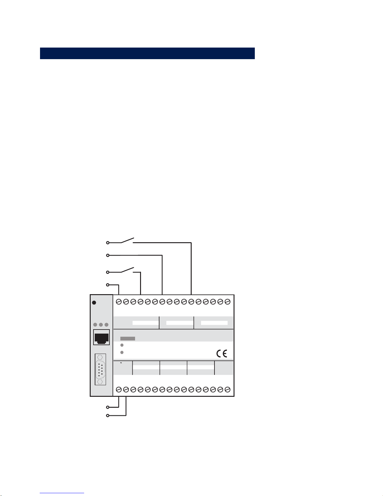
The Web-IO 12+12 Digital has 12 digital inputs divided into 3
groups of 4 inputs. The groups are galvanically isolated from
each other for up to 2kV. A reference ground is brought out for
each input group.
The permitted input voltage range is +/-30V with respect to the
corresponding reference ground.
The switching threshold of the inputs is 8V +/- 1V. Voltages less
than this are interpreted as an OFF or 0 signal. Voltages over 8V
are interpreted by the Web-IO as ON or 1. Input voltages between
7V and 9V should be avoided, since they cannot be definitively
interpreted.
on
error
system error
http:// . . . /diag
0 11109GND 87546321GND
GND
GND
INPUT GROUP 0 INPUT GROUP 1 INPUT GROUP 2
0
11109
GND
87546321Vcc
6-30V DC
+Vdd
OUTPUT GROUP 0 OUTPUT GROUP 1
OUTPUT GROUP 212-24V
Vcc
W&T
www.wut.de
Web-IO #57630
12xDigital-IO <-> 10/100BT
1
23
4
5678
9
10 11 12 13
14 15
16
17 18 19
20 21 22 23 24 25 26 28 29 30
31
32
27
Reset
Power
Status
Error
Serial Port
+12 V
GND 12 V
GND 18 V
+ 18 V
Vcc
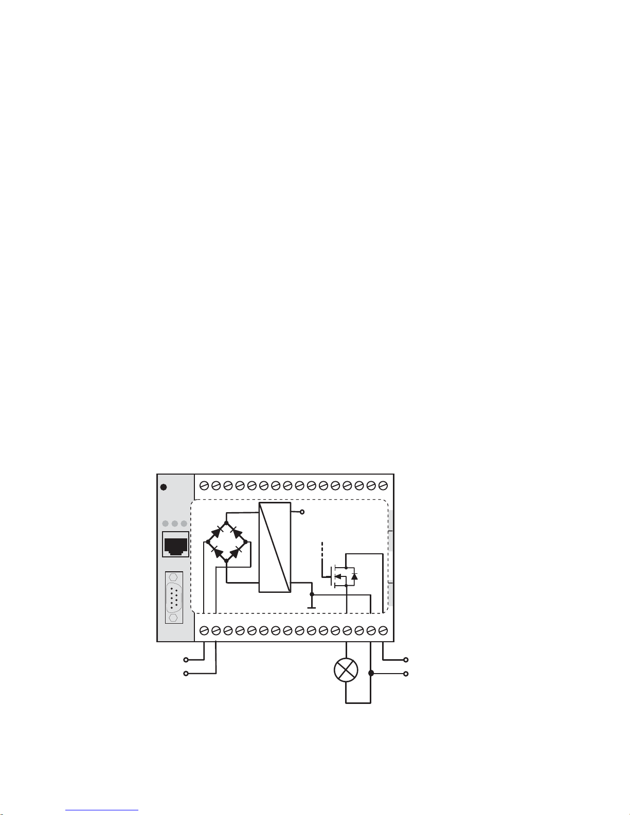
Example of an input circuit
This connection example shows two inputs being driven with
signals from different circuits. It is important that all signals for an
Page 31
31
W&T Connections, operating elements and LEDs
Subject to errors and modifications:
input group have the same ground reference. For signals with
with a different reference ground, the circuit should be
configured in separate input groups as shown in the example.
The cables should not be longer than necessary. Unshielded
cables can be used for lengths under 2m.
Longer runs should always use appropriate shielding measures to
protect against noise. We recommend using shielded cable and/or
ferrite cores as well as separate cable runs to prevent noise
signals from being interpreted as actual signals.
In addition to detecting the input status (ON/OFF), each input also
has a counter. As shipped the edges are counted (state change).
The counters in the first input group can alternately be changed
from edge to pulse counting.
3.6.2 Output circuit
The 12 outputs of the Web-IO are current sourcing. The supply
voltage for the outputs can be between +6 V and +30 V and is
brought in through terminals 16 (Vdd) and 15 (GND).
on
error
system error
http:// . . . /diag
0 11109GND 87546321GND
GND
GND
INPUT GROUP 0 INPUT GROUP 1 INPUT GROUP 2
0
11109
GND
87546321Vcc
6-30V DC
+Vdd
OUTPUT GROUP 0 OUTPUT GROUP 1
OUTPUT GROUP 212-24V
Vcc
W&T
www.wut.de
Web-IO #57630
12xDigital-IO <-> 10/100BT
1
23
4
5678
9
10 11 12 13
14 15
16
17 18 19
20 21 22 23 24 25 26 28 29 30
31
32
27
Reset
Power
Status
Error
Serial Port
Vcc
Vdd
+Vcc
Intern
- Vcc
Intern
~
~
principle diagram
DC
DC
+
-
~
~
Example of an output circuit
Page 32

32
W&T Connections, operating elements and LEDs
Each output can switch a maximum of 500mA. To achieve
higher currents, individual outputs can be combined into
groups of 2 or 4. The maximum switching current is the total
of the individual currents: max. 1A for 2 outputs, max. 2A for 4
outputs
The outputs have thermal overload protection and are short circuit
protected.
Web-based Management can be used to activate load
monitoring, which lets the user know when there is no load
(e.g., cable break) or overload.
When dimensioning the output voltage supply, the required current
should be taken into consideration. If the selected output voltage
varies between 12V and 24V, Vcc and Vdd can also be supplied
from the same source.
Page 33

33
W&T configuring the network parameters
Subject to errors and modifications:
4 Configuring the network parameters
■ Web-Based Management
■ Basic setting of the network parameters
Page 34

34
W&T configuring the network parameters
4.1 Web-Based Management
4.1.1 Basics
The W&T Web-IO 12+12 Digital provides the user with a
complete Web-Based Management system. This means: If the
Web-IO has an IP address, all the settings can be conveniently
made over the network from the browser. Since no devicespecific configuration software is needed, the user is also not
tied to a particular operating system.
Regardless of whether you are using Microsoft Windows, Linux,
Unix, Apple Macintosh, os2… , wherever there is a browser
there is also a way to configure. And the configuration is
always handled the same way regardless of the operating
system.
At this point we would like to explain a few basic principles of WebBased Management and help to understand how this works with
the Web-IO.
4.1.2 Structure of the Web site
When the Web-IO is opened in the browser, a 2-part Web site
always appears. These two parts are also known as frames.
On the left side is always the navigation frame, which one could
compare with the table of contents of a book.
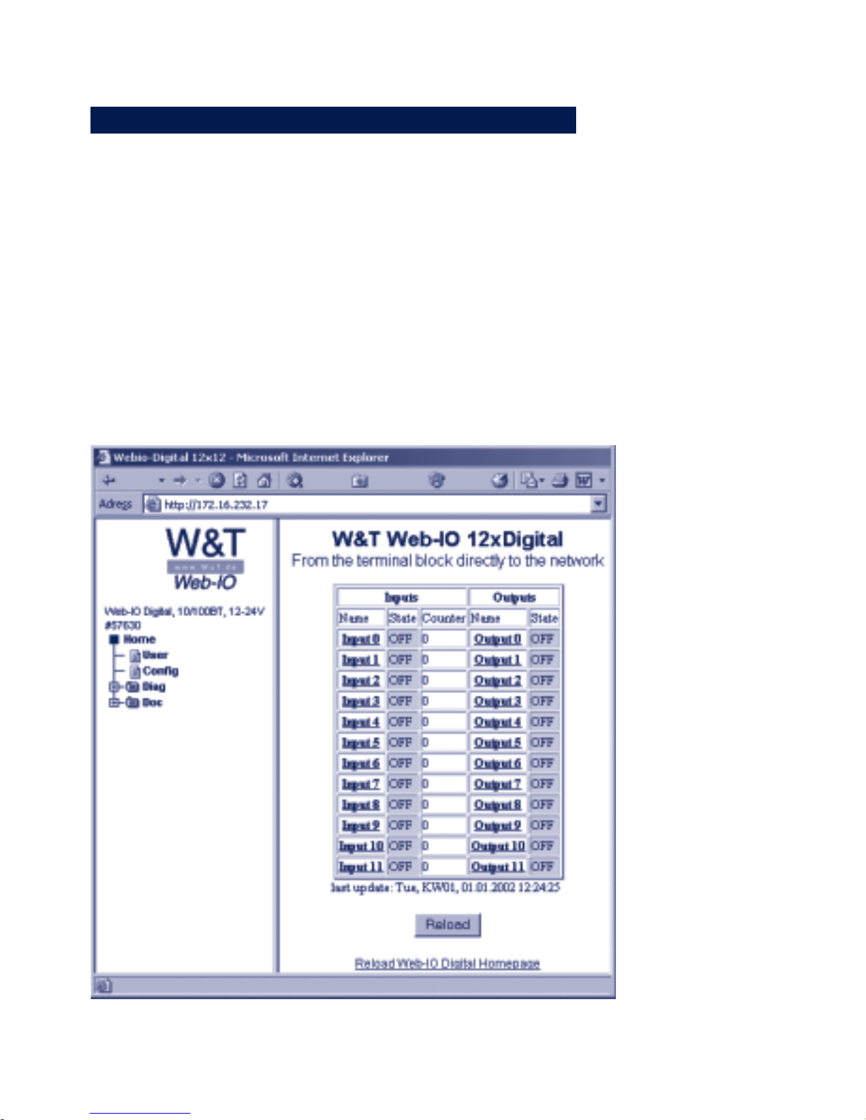
To the right is the display and configuration frame. When the
web site is first opened, this contains the current status of the
inputs and outputs of the Web-IO.
4.1.3 Navigation
The navigation frame contains a directory tree in which all the
available menu items of the Web-IO are listed by categories.
Clicking with the mouse either displays additional menu items for
Page 35

35
W&T configuring the network parameters
Subject to errors and modifications:
a category and/or a new content is built in the configuration
frame.
The icons in the menu tree have the following meaning:
Main or sub-category with branches to additional contents. Clicking
on this icon expands the menu tree.
Main or sub-category with branches to additional contents. Clicking
on this icon expands the menu tree and shows new contents in the
configuration frame.
Indicates that additional sub-categrories or contents are present.
Clicking on this icon expands the menu tree but not the contents
of the configuration frame.
Clicking on this icon closes the expanded directory tree.
Designates a configuration page which is shown in the
configuration frame when this icon is clicked-on.
1
Avoid using the „Forward“ and „Back“ buttons of your
browser. Use only the navigation tree or buttons and
links in the configuration frame to navigate. Otherwise you
could lose parameters buffered in the background when you
jump forward or back.
Page 36

36
W&T configuring the network parameters
4.1.4 Easier navigation with profiles
The Web-IO 12xDigital offers a variety of operating mode and
configuration possibilities. And to get even the first-time user
of the Web-IO off to a good start, we have created profiles for
the most common applications.
After successfully loggin in as an Administrator (the next
section will cover the possible access privileges), the user is
given a choice between configuration using profiles and expert
mode, which does not provide any configuration assistance..
Working with profiles simplifies configuration by color
highlighting the configuration points which are actually needed
for the corresponding mode. Both the menu entries in the
navigation tree and the respective parameters on the
configuration pages are highlighted.
4.1.5 Access rights
Depending on the login, the Web-IO distinguishes among 3
different access rights:
Default User:
Anyone opening the start page of the Web-IO has this
status initially. The status of the inputs and outputs can be
displayed but not modified. No changes to the
configuration are possible.
Administrator:
Clicking on Config in the menu tree and entering the
administrator password gives you full access to the Web-IO.
The start page is refreshed with a significantly expanded menu
tree. As shipped it is not necessary to enter a password, it is
sufficient to click on the Login button.
The next sub-section describes assigning passwords in greater
detail.
Page 37
37
W&T configuring the network parameters
Subject to errors and modifications:
Operator:
The access rights of the operator are limited to setting the
outputs, clearing the counter, changing the alarm outputs and
a few diagnostic activities. The operator has no additional
configuration options. The login in this mode is also
accomplished by entering the password selected for this
access.
The login is done after opening the Web-IO using Config in the
menu tree.
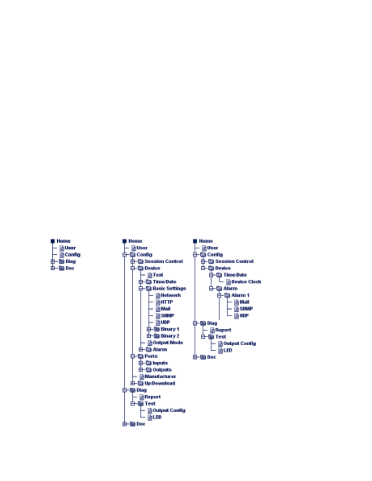
Here again a the menu trees for the various access rights by way
of comparison:
Default User Administrator Operator
Page 38
38
W&T configuring the network parameters
4.1.6 Changing and creating the access passwords
The user must be logged in as an Administrator.
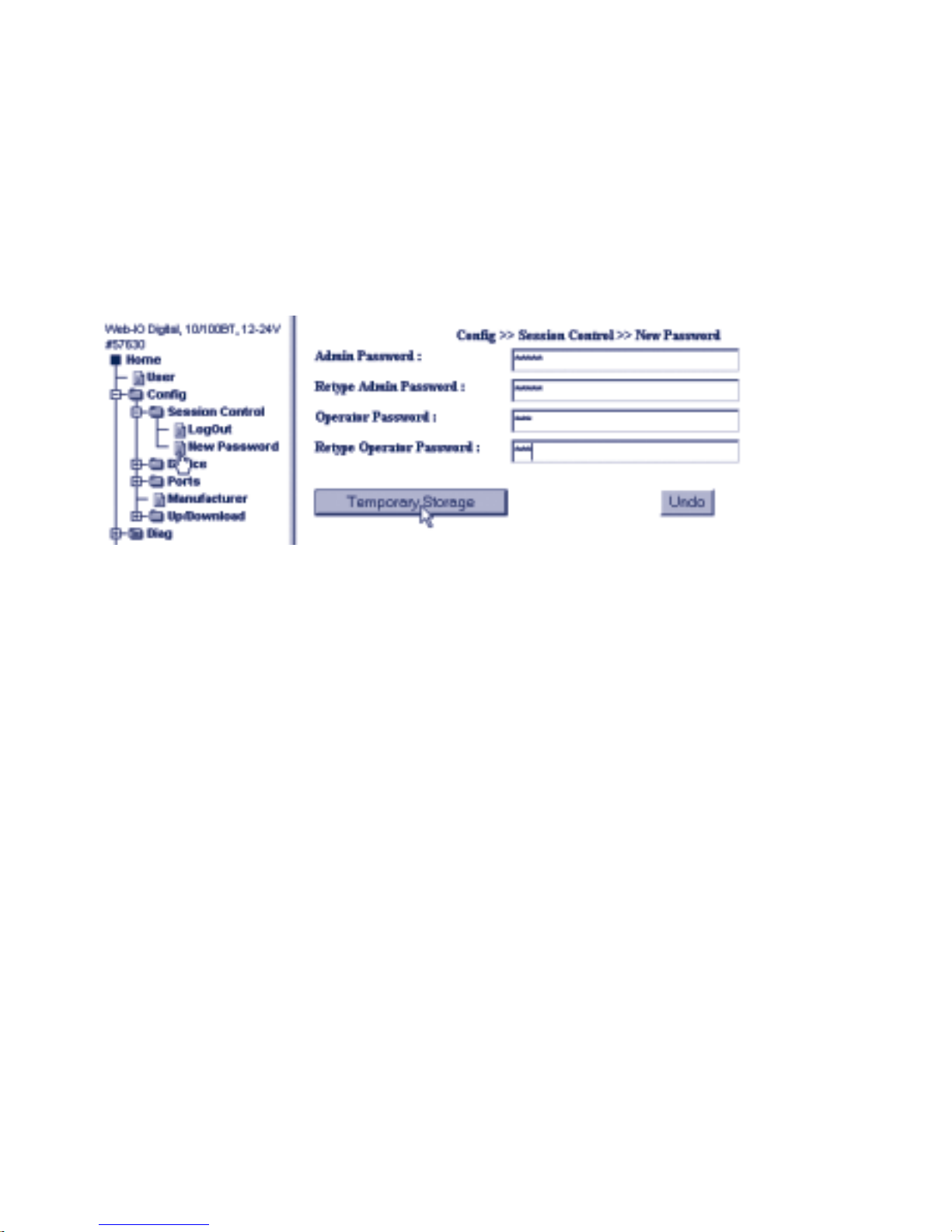
In the navigation tree select: Config >> Session Control >> New
Password and enter the desired passwords in the fields. A
password is limited to 31 characters.
It is not permitted to use the same password for both Admin
and operator access.
Clilcking on the Temporary Storage button sends the new
passwords to the Web-IO. You still have to activate the changes.
Tip: Keep a copy of the passwords in your personal documents.
If you have forgotten the passwords, see the Appendix of this
manual for help.
4.1.7 Saving and activating settings
To increase you understanding of the sequences in Web-Based
Management, first a few basic remarks concerning HTTP protocol:
With HTTP the browser opens a TCP connection to the HTTP
server, requests Web pages and contents from the server or sends
data to the server. The server then immediately closes the
connection.
Page 39

39
W&T configuring the network parameters
Subject to errors and modifications:
Entries made by the user on a Web page are first temporarily
stored by the browser and only sent to the server after clicking on
the Submit or Temporary Storage button through a new TCP
connection.
If for example the browser is closed before the Temporary Storage
button is clicked, the entries are irretrievably lost. This can also
happen if the Web site is changed without sending the entries.
Nearly all the Web sites that can be opened from the navigation
tree offer the possibility of making or changiong entries. Once
you are finished with the entries on such a configuration page,
you must first click on the Temporary Storage button and only
then change to a new Web site.
Once all the entries and configuration changes have been made,
the new settings must still be activated. Use the Logout button
located on each configuration page, or use the menu path
Config >> Session Control >> LogOut.
After clicking on the Save button, all the settings are updated
in the Web-IO and the start page is refreshed in Default User
mode. To make additional setting changes, you must log in
again with the necessary access rights.
Login Timeout
If no entry is made in Adminstrator or Operatotmode for more
than 60 minutes, the Web-IO resets itself to Default User rights.
All entries and changes made to this point, even if they were
already sent to the Web-IO, are lost.
Page 40
40
W&T configuring the network parameters
4.2 Basic setting of the network parameters
Whenever a Web-IO will be used beyond the borders of the local
network, a few additional network parameters are needed in
addition to the IP address.
To be able to perform the configurations described at this point, the
Web-IO should already have an IP address for the network. If this
is not the case, or if the current IP address of the Web-IO is
unknown, first perform the steps described in section 2.
If the Web-IO already has an IP address, enter this in the URL field
of your browser. After a few seconds the start page of the Web-IO
will appear.
Select Config in the navigation menu.
Page 41
41
W&T configuring the network parameters
Subject to errors and modifications:
You are now prompted to enter the correct administrator
password. As shipped there is no password required, and it is
sufficient to click the Login button.
Once the correct password has been entered, the Web-IO
confirms successful login. After clicking on OK, the start page is
refreshed.
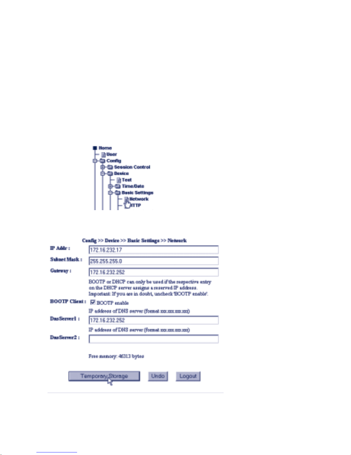
Now go to the navigation menu and select Config >> Device >>
Basic Settings >> Network.
The following screen appears:
Enter here the required network parameters.
Page 42

42
W&T configuring the network parameters
IP Addr.
The IP address may be changed at this point.
Subnet Mask / Gateway
For data exchange throughout the subnet, the appropriate subnet
mask and IP address of the gateway must be entered.
BOOTP Client
If the Web-IO will not participate in central IP addresss assignment
via BOOTP, uncheck BootP enable.
DNS Server
With some network devices, such as mail and time servers, it
makes sense to address them not by their IP address but rather
using a name. For this a DNS server must be specified.
If you do not have the required information, contact your
network administrator.
When you have made all your entries, click on the Temporary
Storage button. This sends the parameters first to the Web-IO.
The changes do not become effective until they have been
activated. For this use the Logout button or menu path
Config >> Session Control >> LogOut.
After clicking on the Save button, the Web-IO is restarted with
the current parameters. Normally the start page of the Web-IO
is refreshed within about 10 seconds. If it does not refresh, click
on the here link.
1
Note that applications which are communicating with the
Web-IO at this point in time may experience a fault.
Page 43

43
W&T configuring the network parameters
Subject to errors and modifications:
The Web-IO is now set up to the point that it can also be
accessed throughout the subnet.
i
If you like to learn more about the expressions and
names used, ask for a free copy of our book TCP/IP-Ethernet and Web-IO, where the necessary basics for starting up
network components are explained. WWW.WUT.DE
Page 44

44
W&T configuring the network parameters
Page 45

45
W&T Access types
Subject to errors and modifications:
5 Access types
■ Overview
■ HTTP - Controlling inputs and outputs in the browser
■ Java Applets - Automatic refreshing in the browser
■ TCP/UDP - Controlling the Web-IO using sockets
■ Box-to-Box
■ OPC
■ SNMP
■ Alarms
Page 46

46
W&T Access types
5.1 Possible operating modes - An overview
After successfully configuring the TCP/IP parameters, the W&T
Web-IO 12+12 Digital provides a wealth of different operating
modes, functions and services.
The functions can be divided into groups:
. Basic Operating Modes
. Alarm Service
. Input/Output Service
. System Service
5.1.1 Basic operating modes
Five different operating modes and communication paths can be
used for setting and monitoring the inputs and outputs.
You must specify for each individual output in which mode you
want it to operate. To prevent access conflicts, the output is only
available for this mode and cannot be accessed in any other way.
The inputs and counters on the other hand can be read equally in
all operating modes.
HTTP - browser access
This mode can be used immediately without additional
configuration using the factory defaults. Browser access to the
outputs is however only possible with Administrator or Operator rights. Java applets can be incorporated into your own Web
pages for a current display of the input states.
TCP socket strings (ASCII)
In this mode the inputs and outputs can be controlled by sending
command strings via TCP. TCP access can also be used without
additional configuration using the factory defaults.
UDP socket strings (ASCII)
Just as with TCP socket string mode, the inputs and output can be
controlled by sending command strings. Access via UDP must first
be enabled by the administrator.
Page 47

47
W&T Access types
Subject to errors and modifications:
SNMP
The inputs and outputs can be controlled using a private MIB. The
configuration of the Web-IO can also be affected. Access to the
outputs must first be activated for this mode.
TCP/UDP-Binary I and Binary II
These modes allow fast, flexible socket access, with
communication handled by exchanging binary structures.
For this the Web-IO provides two independent sockets (Binary I
and Binary II), which can be operated as TCP server, TCP client
or UDP peer. It is possible to incorporate password protection
when opening a connection to protect the application from
undesired access by third parties.
In addition to standard client and server applications, the Web-IO
offers three other application modes in binary mode:
. Box-to-Box
In this mode the inputs on Web-IO correspond to the
outputs of a second and vice-versa.
. 50xxx-compatibility mode
To operate the Web-IO with applications that have been
programmed for W&T Digital I/O Com-Servers (predecessors
to the Web-IO 12+12 Digital), a compatibility mode is
available. Access in this mode is possible without password
protection.
. OPC
In OPC mode the Web-IO 12+12 Digital allows access from
process and visualization systems through the Wiesemann
& Theis OPC server, which can be downloaded free of charge
from our Web site.
Page 48
48
W&T Access types
SMTP-Mail
HTTP
SNMP-Trap
TCP / UDP
Box-to-Box
50xxx-Mode
SNMP
Web-Based
Management
Time
Firmware
Update
Logic Control
Input Group 0 Input Group 1 Input Group 2
Safety Output on Network Error
Load Control
Output Group 0 Output Group 0 Output Group 0
Ethernet / IP-Interface
TCP/UDP
System Service
Basic Service
Alarm Service
IO Service
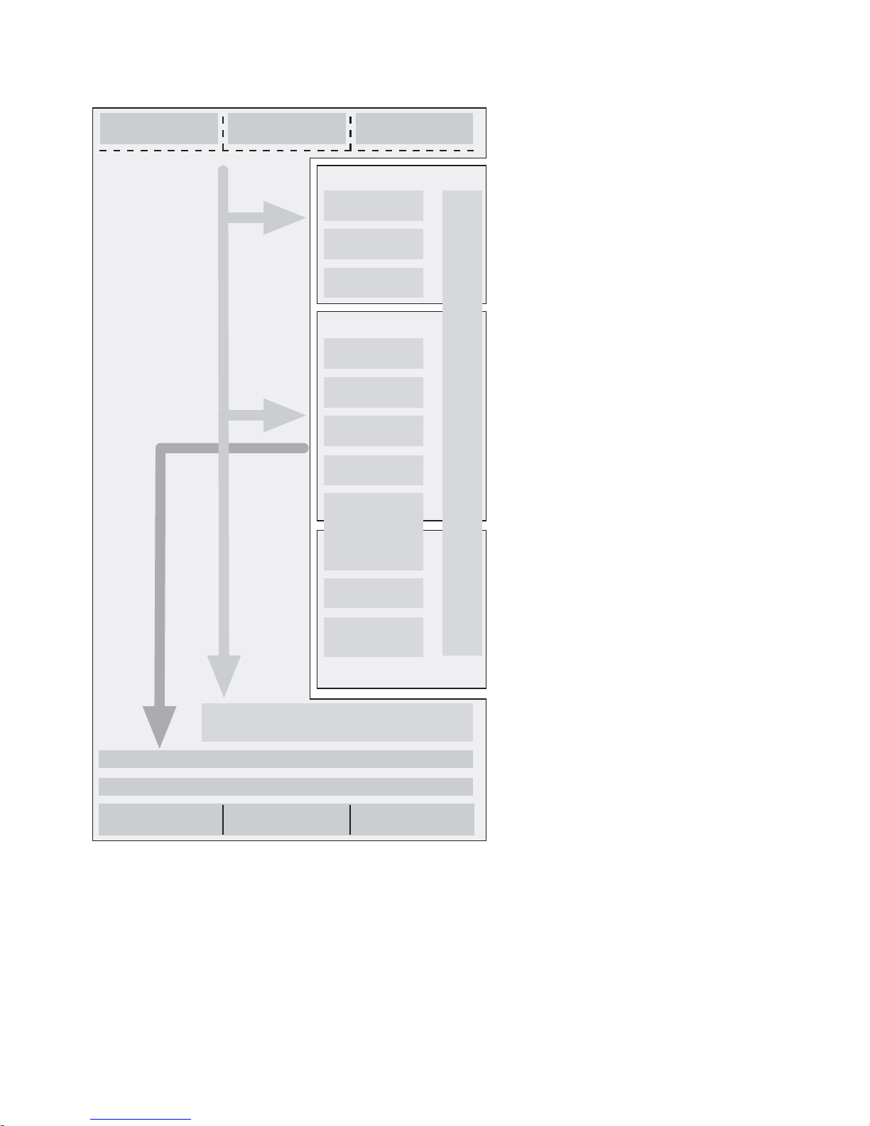
The block diagram above shows an overview of the various
services and modes.
Page 49

49
W&T Access types
Subject to errors and modifications:
5.1.2 Alarm service
Along with the basic operating modes, 12 various alarms can be
defined in the Web-IO The following alarm conditions can be
configured for each individual alarm:
. Certain patterns of input and output states
. Counter states
. Overload errors
. Timer interval (for cyclical alarming)
The following communication paths are available for the alarm
output:
. SMTP (E-mail)
. SNMP trap
. UDP
. TCP
5.1.3 Input /Output service
In addition to the ph
ysical properties of the inputs and outputs (See section Con-
nections, operating elements and LEDs) the Web-IO 12+12 Digital has logic and monitoring functions.
Output groups
The outputs can be divided into groups of two or four to increase
the maximum switching current of 500mA.
1
Outputs that work in a group always switch at the same
time, even if only one output was triggered! This makes
it absolutely essential to use the outputs in a group using the
same mode.
Logic functions
The individual outputs can be controlled as a function of
configurable input patterns.
Page 50

50
W&T Access types
One example: Output 11 can be configured so that it is set to
ON when Input 0 = ON and Input 1 = Off. If this condition is
not met, Output 0 = OFF.
1
Outputs that were configured for such a logic function
can no longer be controlled by the basic operating
modes.
Safety Output
A safety pattern can be defined for the outputs. If the Web-IO does
not detect any network activity during a configurable timeout, the
outputs are set to this safety pattern. As son as triggering from the
network side resumes, the outputs are set to their original state
and can be controlled normally.
Load Control
The outputs have thermal protection and are monitored by the
Web-IO for overload or the absence of a load. In case of error the
outputs are turned off.
5.1.4 System Service
In addition to the Web-IO functions that directly access inputs and
outputs, there are a few additional important system functions.
These include:
. Web-Based Management
. System clock incl. time server synchronization
. Capability for firmware update
i
All the functions briefly described here are covered in
greater detail in the following sections.
Page 51
51
W&T Access types
Subject to errors and modifications:
5.2 Specifying the output mode
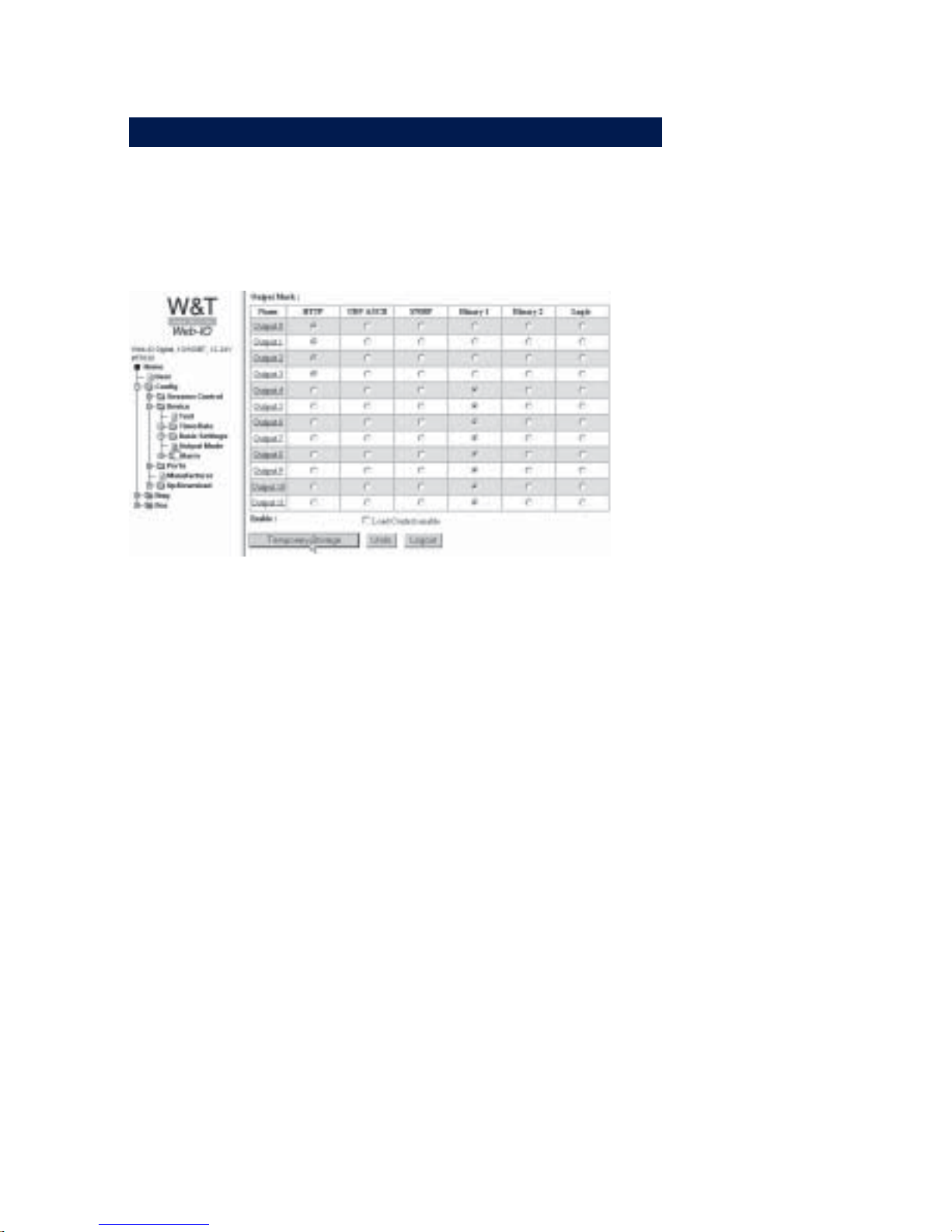
As already described, you must specify in which mode each individual output is supposed to work. The corresponding
configuration can be made under Config >> Device >> Output
Mode.
m Required access rights: Administrator
Output Mode
Here the mode used for each output is specified. The factory
default is for all ports HTTP. Please note that in most modes a
few additional settings besides output mode need to be made,
such as enabling of the mode. For more detailed information,
refer to the description of the respective operating mode.
Safety Timeout
If no network activity is detected for the timeout period set here,
the Web-IO sets the outputs to a configurable output pattern.
Which outputs should be involved and what their status should
be is configured under Config >> Ports >> Outputs. A detailed
description of the safety timeout and safety state can be found
in the section Safety State / Timeout.
Load Control:
By activating this option you are enabling load monitoring. Load
monitoring applies to all outputs.
After selecting the output modes, click on Temporary Storage to
send the settings to the Web-IO. To activate, use the Logout button
and click on Save.
Page 52
52
W&T HTTP - Inputs and Outputs control from the Browser
5.3 HTTP - In- and Output control from the browser
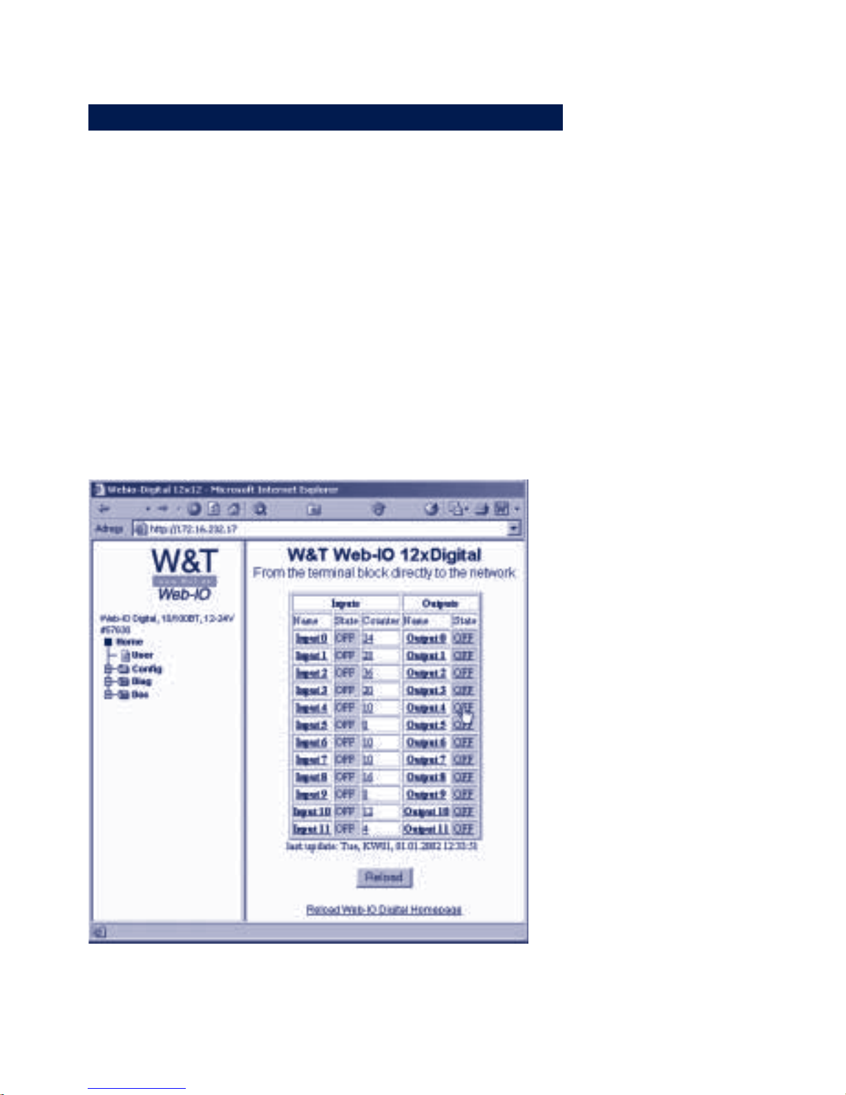
Access from the browser is the easiest way to use the Web-IO
12+12 Digital for most users.
The input status is displayed right on the start page.
. Status = ON indicates that the input voltage >= 12V was
detected on the input
. Lower voltages are indicated by Status = OFF. Status ON is
also highlighted by a green background on the table field.
. In addition the counter status for the individual input
counters can be read.
To use the output from the browser, it is necessary to log in as
Administrator or with Operator rights.
After a successful login the status indications for the outputs
(ON/OFF) are given a link. Clicking on the corresponding link
Page 53
53
W&T HTTP - Inputs and Outputs control from the Browser
Subject to errors and modifications:
changes the state on the output of the Web-IO and the browser
display is refreshed.
The counter states of the inputs also have a link. Clicking on
the link sets the corresponding counter to 0.
5.3.1 Labeling and texts
m Required access rights: Administrator
The appearance of the Web-IO pages in the browser can be
individually designed and changed within certain limits.
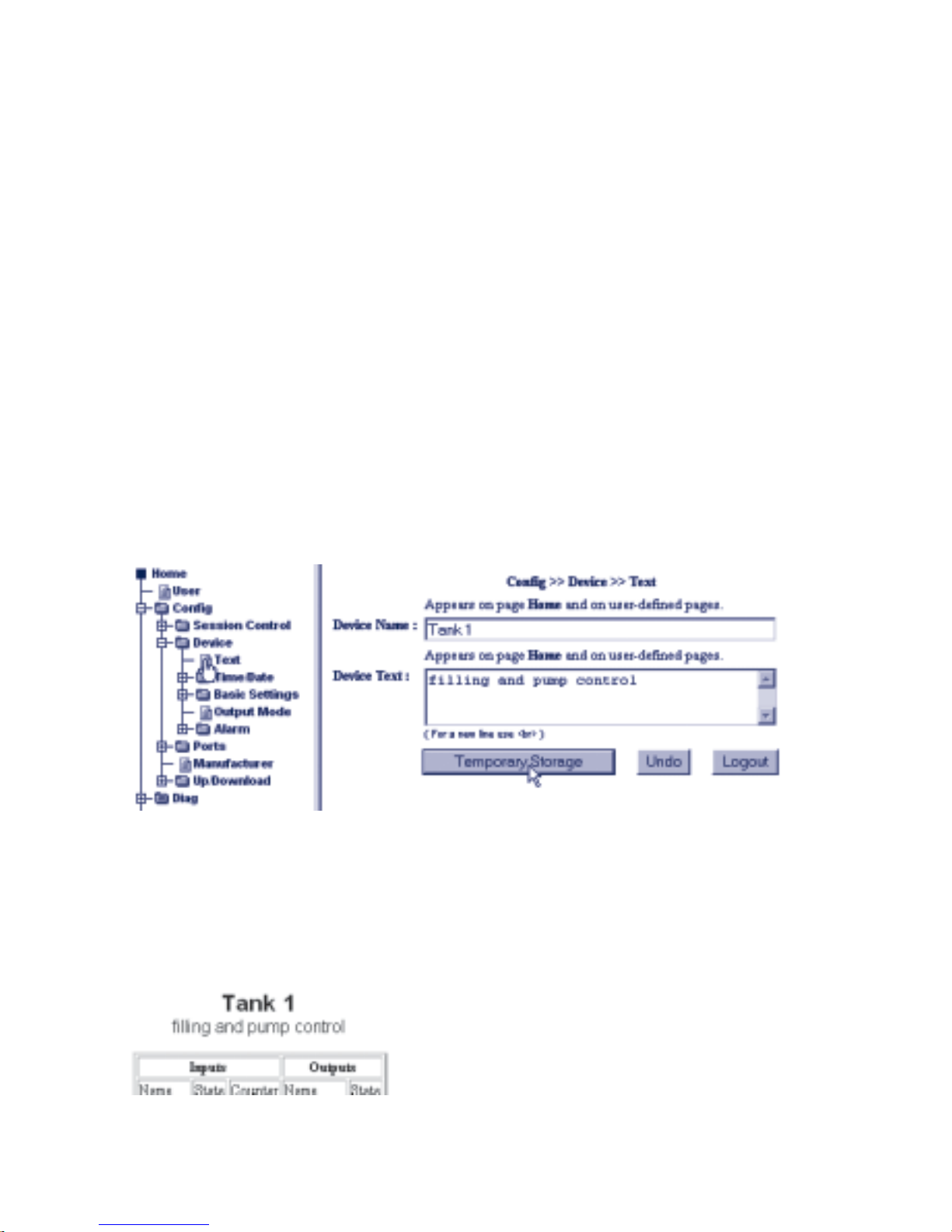
Device name and description
In the navigation tree under Config >> Device >> Text you can
change device name and description of the Web-IO.
If the description takes up more than one line, insert the <br> tag
where the line break needs to be made.
In the browser window you can adapt the display after sending and
activating the settings.
Page 54

54
W&T HTTP - Inputs and Outputs control from the Browser
Port name and description
You can also set up individual names and descriptions for the
inputs and outputs.
To change the input name, select in the navigation tree
Config >> Ports >> Inputs and for Input 0 >> Input 0:
I
Please do not make any changes to the settings for Input
Mode at this time. For detailed information about these
parameters, refer to section General Settings.
For changes to the output names select
config >> Ports >> Outputs and for example >> Output 0 for
Output 0
Page 55
55
W&T HTTP - Inputs and Outputs control from the Browser
Subject to errors and modifications:
I
Please do not make any changes to the settings for
Group Mode and Safety State at this time. For detailed
information about these settings, refer to section General Set-
tings.
In the browser window you can adapt the display after sending and
activating the settings.
Clicking on the name of the inputs and outputs opens the
associated description.
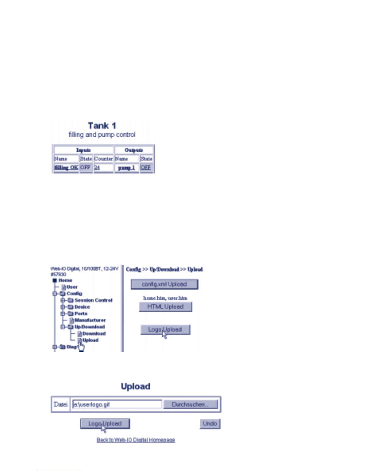
Logo in navigation frame
To enable a customized as possible appearance of the Web-IO
start page, it is possible to replace the W&T logo in the navigation
frame with any logo of your choice. Select in the navigation tree
Config >> Up/Download >> Upload
Click on the button logo upload.
Page 56
56
W&T HTTP - Inputs and Outputs control from the Browser
Select the desired JPG- or GIF file and click on the button logo.gif
upload.
Note that the dimensions of the logo must agree approximately
with those of the W&T logo (width max. 200 pixels, height max.
100 pixels) so that the navigation frame can be seen in its entirety.
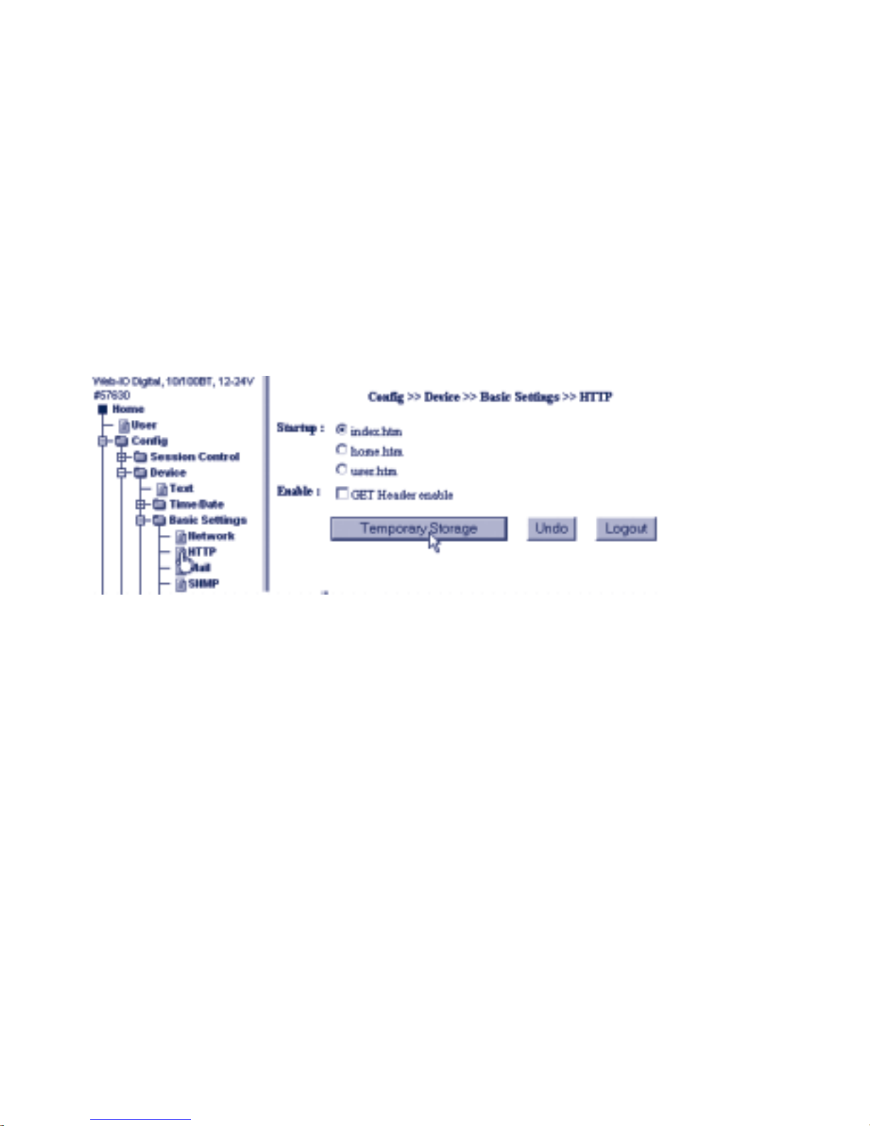
Display at start
Select in the navigation tree Config >> Basic Settings >> HTTP
m Required access rights: Administrator
Startup
Here you can specify how the Web-IO is displayed in the
browser when opened.
. index.htm
Both the navigation tree and the Homepage are displayed.
. home.htm
Only the Homepage is shown, not the navigation tree.
. user.htm
Only the user page is shown, without the navigation tree.
The Item GET Header enable has no effect on the appearance
of the Web site and is described in greater detail in the section
Socket programming with command strings.
In the browser window you can adapt the display after sending and
activating the settings.
Page 57

57
W&T HTTP - Inputs and Outputs control from the Browser
Subject to errors and modifications:
After you have made all your settings, use the Logout button
located on each configuration page or select >> Session
Control >> LogOut in the Config menu.
After clicking on the Save button, all the Web-IO settings are
updated and the start page is reopened in Default User Mode.
5.3.2 Creating your own Web site for the Web-IO
m Required access rights: Administrator
The start or home page contains a clear summary of all the WebIO functions available in the browser.
It is also possible to create another Web site designed more
according to your own needs and to make it accessible in the
Web-IO.
To incorporate the Web-IO-specific display objects and control
elements, the Web-IO supports special HTML tags.
These tags consist of
<w&t_tags=
and the actual function invoking.
<w&t_tags=time>
for example displays the current system time in addition to the
date.
The following functions are available:
Page 58
58
W&T HTTP - Inputs and Outputs control from the Browser
Invoke / Ta
g
Function
device_name
Inserts the name assi
g
ned for the Web-IO in the web site
device_text
Inserts the description defined for the Web-IO in the web site.
inputx
Inserts the name specified for input no. x.
x can be a number between 0-11 and indicates which
input the invoke refers to. This applies as well to the
output and counter invokes described below.
ix
Indicates the state (ON/OFF) of the input corresponding to x.
bcix
Represents the background of a table cell depending on the
state of Input x.
OFF = no back
g
round color, ON = green.
cx
Inserts the counter state of the counter for Input x in the web
site.
outputx
Inserts the name specified for Output x.
ox
Shows the state (ON/OFF) of the output corresponding to x.
When logging in with Operator or Administrator rights, the
state indication is given a hyperlink. Clicking on this link
changes the state of the corresponding output and refreshes
the web site.
bcox
Represents the background of a table cell depending on the
state of Output x.
OFF = no back
g
round color, ON = green.
time
Inserts the system time and data of the Web-IO in the Web
site.
reload_button
Inserts a button having a reload function in the Web site.
session
When logging in with Operator or Adminstrator rights, the Web
-
IO generates a Session ID. When the page is opened again
this Session ID must be specified as a parameter, so that for
example when jumping back through a link the access rights
are retained.
An example for using W&T tags
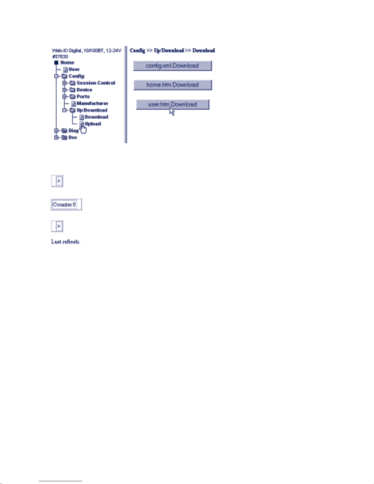
The page user.htm can be used as a basis for creating your own
Web pages. To view the original source text, select in the
navigation tree Config >> Up/Download >> Download and then
click on the button user.htm download.
Page 59
59
W&T HTTP - Inputs and Outputs control from the Browser
Subject to errors and modifications:
The following Web page then appears in the viewing frame:
In most browsers right-clicking displays the source text of a Web
site. The unaccustomed appearance of the Web site results from
the fact that when opening the page via download the original
HTML code with the W&T tags is loaded into the browser. When
user.htm is normally opened the Web-IO replaces the W&T tags
with the HTML code filled with the current values.
The top line of the HTML code always begins in the Web-IO with
the name of the Web site. In this case:
<user.htm>
Then follows the usual HTML header.
<!DOCTYPE html PUBLIC "-//W3C//DTD HTML 4.01 Transitional//EN">
<html>
<head>
<title>Example for user.htm in the Web-IO</title>
<meta http-equiv="Content-Type" content="text/html; charset=iso-8859-1">
Page 60

60
W&T HTTP - Inputs and Outputs control from the Browser
</head>
<body>
<p>Diese Webseite zeigt anhand .....</p>
The W&T tags can be used to insert not only normal HTML
elements but also Web-IO-specific contents.
<w&t_tags=device_name>
<br><w&t_tags=device_text>
displays the device name and designation when the user Web site
is opened:
The states of the inputs are best displayed in the form of a 2column table. In the following example Column 1 contains the
designation and Column 2 the state of Input 0:
<table border="1" cellspacing="2" cellpadding="2">
<tr>
<td><w&t_tags=input0></td>
<td <w&t_tags=bci0>><w&t_tags=i0></td>
</tr>
</table>
In the browser this looks as follows:
Using this method you can also incorporate counters
<table border="1" cellspacing="2" cellpadding="2">
<tr>
<td>Counter 0</td>
<td><w&t_tags=c0></td>
</tr>
</table>
and outputs
Page 61

61
W&T HTTP - Inputs and Outputs control from the Browser
Subject to errors and modifications:
<table border="1" cellspacing="2" cellpadding="2">
<tr>
<td><w&t_tags=output0></td>
<td <w&t_tags=bco0>><w&t_tags=o0></td>
</tr>
</table>
When opening the user web site using Administrator or
Opertator rights, the status of the outputs also has a link which
allows the state of the output to be changed by clicking on the
link.
You can also show the time when the user Web site was opened.
Last refresh: <w&t_tags=time>
By inserting a reload button you allow the user to get the current
states of the Web-IO at any time.
<form method="get" action="user.htm">
<p><w&t_tags=reload_button></p>
</form>
The user Web site is closed in the conventional manner with
</body>
</html>
.
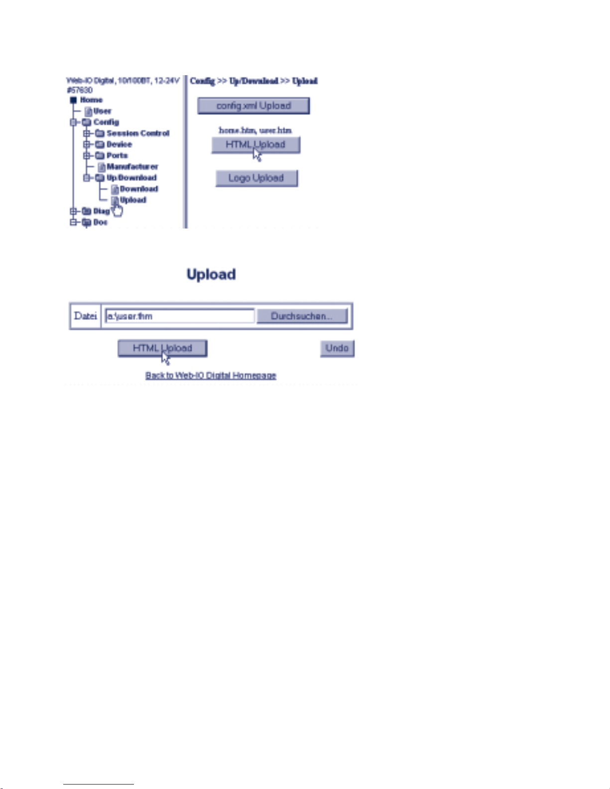
After you have finished creating the user Web site, you must still
upload it to the Web-IO.
Select in the navigation tree Config >> Up/Download >> Upload
Page 62
62
W&T HTTP - Inputs and Outputs control from the Browser
and click on HTML-Upload
Once the upload is completed, the new settings still must be
saved.
In the Config menu select >> Session Control >> LogOut.
After clicking on the Save button, the Web-IO is restarted and the
newly created Web site can be opened.
Links and back links
Some applications may make it necessary to link from the user or
home page of the Web-IO to a Web site which is located on
another HTTP server.
If a back link then navigates you back to a Web-IO page, this is
done using standard user access rights, even if before there was
an Administrator or Operator login.
To enable a back link with the existing access rights, there is the
<w&t_tags=session> tag. This tag is a placeholder for a session
ID.
Page 63

63
W&T HTTP - Inputs and Outputs control from the Browser
Subject to errors and modifications:
The corresponding link would then have to be inserted in the
page as follows:
<a href="http://wut.hs2/webioback.htm<w&t_tags=session>" target="_top">Testlink </a>
When the link is opened, the Web-IO replaces the session tag with
the session ID and passes it to the newly opened Web site.
To use the session ID for a back link, a small Javascript must be
inserted into the external page which accepts the session ID
when opening the page and inserts it in the back link.
<html><head>
<script language="JavaScript">
session=window.location.search
function setbacklink() {
var backlinkurl = "http://172.16.232.17/index.htm";
var backlink = backlinkurl.concat(session);
window.location.href = backlink;
}
</script>
In the body area of the page the function setbacklink can be used
as a hyperlink.
</head><body>
A test page is now opened with the passed session. <a href="javascript:setbacklink();"
>Open
test page</a>
</body></html>
This ensures that the access authorization remains intact after
jumping back to the Web-IO.
Page 64

64
W&T Java Applets
5.3.3 Java Applets - Auto-updating in the browser
Visualization of states in the browser, based on pure HTTP or
HTML, permits only a snapshot. Displayed is the status at the
time the Web page was opened. A status change can only be
displayed by reloading the complete Web page.
To allow current states to be displayed in the browser, a Java
applett is implemented in the Web-IO 12xDigital.
In order to permit the most flexible utilization, the Java applet
opens pre-defined JavaScript functions which must be declared
in the header of the HTML page.
In addition the Java applet provides functions which allow you
to set outputs and clear counters using JavaScript.
Working with the Java applet
The applet is incorporated using the <applet> HTML tag, where
the standard parameters archive and code are set as follows:
archive="dio.jar"
code="dio.class"
The remaining parameters are set individually according to the
application.
name=“dio0“
The designator dio was chosen randomly here and can be
replaced with any desired. The only stipulation is that the same
name is used when invoking the applet functions with
JavaScript.
codebase="IP-Address of the Web-IO"
If the Web page from which the applet is loaded is loaded
directly from the Web-IO as user.htm or home.htm, the
codebase parameter is not needed.
Page 65

65
W&T Java Applets
Subject to errors and modifications:
width="0" Specified in pixels
height="0" Specified in pixels
Since the applet does not contain a visual component, width
and height should always be 0.
In addition you can set several more Web-IO-specific
parameters which are inserted in a separate <param> tag:
device
Whole-number value between 0 and 255. The device parameter
is used for indexing when more than one Web-IO needs to be
operated on a Web site.
If working with just one Web-IO, set the value to 0. For all additional Web-IOs being incorporated into the Web site, the value
is raised by 1.
showerrors
If errors occur when using the Java applet, this parameter can
be used to specify whether an error message in the form of an
alert window should be generated.
inputpolling
This parameter is used to specify when the applet is started
whether the inputs should be checked for their state at the
interval set under pollingrate.
Als value kann für inputpolling on oder off gesetzt werden.
In order to reduce the data load on the network, you can use
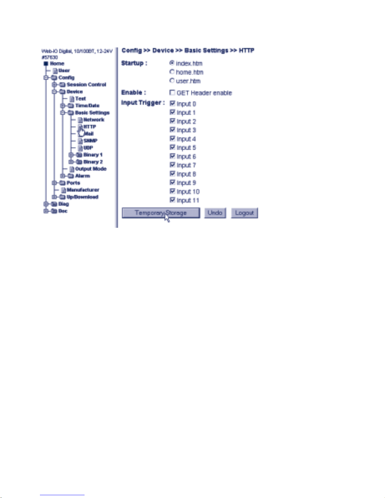
the navigation tree of the Web-IO under Config >> Device >>
Basic Settings >> HTTP to set the Input Trigger for the
monitored inputs.
Page 66
66
W&T Java Applets
In this case value can be set to off. This means there is a data
load for updating the inputs when an input changes.
For the changes to the input trigger to become effective, the
new settings must be saved under Control >> Logout.
outputpolling
This parameter is used to specify when starting the applet
whether the outputs should be checked for their state at the
interval set under pollingrate.
The value for outputpolling can be set to on or off.
counterpolling
This parameter is used to specify when starting the applet
whether the counters should be checked for their state at the
interval set under pollingrate.
The value for counterpolling can be set to on or off.
Page 67

67
W&T Java Applets
Subject to errors and modifications:
pollingrate
Mit diesem Parameter wird durch value festgelegt, in welchem
Intevall (in ms) Inputs, Outputs oder Counter aktualisiert werden sollen.
Here is an example:
<applet name="dio0" archive="dio.jar" code="dio.class"
codebase="http://172.16.232.11" width="0" height="0">
<param name="device" value="0">
<param name="showerrors" value="off">
<param name="inputpolling" value="on">
<param name="outputpolling" value="on">
<param name="counterpolling" value="on">
<param name="pollingrate" value="2000">
</applet>
1
Both the parameters and the values are case-sensitive.
Using the applet with JavaScript
To work with the applet, corresponding JavaScript functions
must be declared in the header of the Web page.
There are 4 functions for read-only access:
Password protection
<script language="JavaScript" type="text/javascript">
<!-function setPassword()
{ document.applets["dio0"].setPassword('Administratorpasswort');}
If an Administrator or Operator password has been set for the
Web-IO, the setpassword function must be invoked so that you
can work with the applet. Instead of a static password, the
password may of course also be queried by the user using an
input field and then passed on.
Page 68

68
W&T Java Applets
In any case, setPassword can only be invoked once the Java
applet has been started, since otherwise runtime errors would
occur.
i
An example in which the password is passed on using an
input field can be found by opening the Web page
app.htm in the Web-IO.
Read functions
function inputChanged( iDevice, iNr, iVal )
{ Program code executed when there is a change on the inputs}
function outputChanged( iDevice, iNr, iVal )
{ Program code executed when there is a change on the outputs}
function counterChanged( iDevice, iNr, iVal )
{ Program code executed when there is a change in the counters}
The three functions above are invoked by the applet when there
is a change on the inputs or outputs or in the counters. iDevice
shows on which device a change has happened. iNr specifies
which input, output or counter has changed. The variable iVal
conveys the current state.
1
Please note that the names of the functions are
case-sensitive.
The following source code shows a short example for dynamic
display of Input 0.
<html>
<head>
<script language="JavaScript" type="text/javascript">
<!- function inputChanged( iDevice, iNr, iVal )
{ if (iNr == 0 && iDevice==0)
{ document.getElementById( 'input' + iNr ).firstChild.nodeValue
= ( !iVal ) ? 'OFF' : 'ON';
}
else
{ iVal = 0;
}
}
Page 69

69
W&T Java Applets
Subject to errors and modifications:
function setPassword()
{ document.applets["dio0"].setPassword( 'wut');
}
//-->
</script>
</head>
<body>
<applet name="dio" archive="dio.jar" code="dio.class"
codebase="http://172.16.232.11" width="0" height="0">
<param name="device" value="0">
<param name="showerrors" value="off">
<param name="inputpolling" value="on">
<param name="outputpolling" value="off">
<param name="counterpolling" value="off">
<param name="pollingrate" value="1500">
</applet>
<p>State of Input 0:</p>
<p id="input0">OFF</p>
<script language="JavaScript" type="text/javascript">
<!- setPassword();
//-->
</script>
</body>
</html>
Das Beispiel beinhaltet nur die Funktion inputChanged, da im
Bereich des Applet-Tags nur das inputpolling aktiviert wurde.
1
The following applies when processing inputs, outputs
and counters: If the corresponding polling is activated,
the associated JavaScript function must be declared in the
HTML text to prevent runtime errors.
1
To automatically provide the password when opening
the Web page, invoking of the setPassword function must
stand behind the applet tag.
In this case the password is stored unencoded in the source
text. For security reasons we therefore recommend password
prompting using an input field.
Page 70

70
W&T Java Applets
Write functions
To allow individual access to the outputs, the applet provides
corresponding functions.
function setOutput( iDevice, iOutput, iValue )
{ iOut = 0;
iOut |= Math.pow( 2, iOutput );
document.applets["dio"+iDevice].outputAccess( iOut, iValue );
}
If you want to access the outputs using JavaScript, the above
function should be inserted in the Web page header. iOutput
indicates which output should be set. iValue is set to 0x0FFF if
the output is supposed to switch to ON. 0x000 corresponds to
OFF.
The JavaScript command
document.applets["dio"+iDevice].outputAccess( iOut, iValue )
is used within the function. If you want to switch more than
one output at a time, you can use this command in separate
functions. The variable iOut is a whole-number 16-bit value. By
using for example mathematical functions or including
constants you can set the bits than need to be changed to 1.
In iValue you specify for the individual bits whether the
corresponding output should be 0 (=OFF) or 1 (=ON).
Example in hex format:
iOut = 0x0013, iValue = 0x0101
In this case, Outputs 0 and 4 are set to ON and Output 1 to 0.
All other outputs remain unchanged.
An additional function is provided for clearing the counters.
function clearCounter( iDevice, iValue )
{ iVal = 0;
iVal |= Math.pow( 2, iValue );
document.applets["dio"+iDevice].counterClear( iVal );
}
Page 71

71
W&T Java Applets
Subject to errors and modifications:
When this function is invoked, iValue indicates which of the
counters is to be cleared.
Limits when using the Java applet
When the Web-IO is accessed using the Java applet, there are
differences in how this is done depending on the browser.
All Mozilla-based browsers as well as Opera do not allow write
accesses to the Web-IO using the applet if the corresponding
Web page for example is loaded by the local hard drive of the
PC or by a Web server. If no password is assigned on the WebIO, read access can at least be used.
Microsoft Internet Exlorer on the other hand can be used
without limitations.
To be able to work with the Web-IO without restrictions, we
recommend saving the Web page as home.htm or user.htm in
the Web-IO. In this case the newest releases of most browsers
will allow unrestricted access.
The number of users who can use a Web page working the the
Java applet is limited to 3 at a time (if other access types than
HTTP are used, for example BINARY or UDP-ASCII, the number
of possible users is reduced).
i
A comprehensive example for using the Java applet can
be found on the Web page app.htm in the Web-IO.
Open: http://<ip-adresse>/app.htm
Page 72

72
W&T Controlling the Web-IO with TCP/UDP Sockets
5.4 Controlling the Web-IO with TCP/UDP Sockets
To access the Web-IO directly from your own applications, two
basic methods are provided for using TCP or UDP sockets to read
inputs and counters and set outputs.
Access via:
. command strings ASCII
. binary structures BINARY
5.4.1 Selecting the appropriate access mode
Command strings ASCII
In this mode the Web-IO works as a TCP server or as a UDP peer.
Inputs and counters can be read and outputs set by exchanging
simple command strings.
Inputs are generally read by using polling. Event-controlled
processing is only conditionally possible for imput patters defined
in alarms.
Advantages:
. Since all higher level languages such as Visual Basic, Visual
Basic for Applications, Delphi, C, C++, etc. allow
uncomplicated handling of string variables, even
inexperienced programmers will have little difficulty
achieving the desired results.
. Under TCP Port 80 is used (otherwise HTTP), which is
not blocked by most firewalls. This means that mostly
no changes to the netework infrastructure are
necessary.
. Using string variables together with TCP Port 80 makes
it quite easy to integrate communication with the WebIO into PHP and CGI scripts. The Web-IO can also be
accessed from PLCs and other microcontrollers as long
as there is a network connection.
Page 73

73
W&T Controlling the Web-IO with TCP/UDP Sockets
Subject to errors and modifications:
Disadvantages:
. Only partial event-controlled programming possible.
This limits its usefulness for time-critical applications.
. Only client applications possible, no server applications.
Binary structures BINARY
In this mode the Web-IO can function as a TCP client, TCP
server or UDP peer. Access can be password-protected.
The Web-IO defines binary structures for the various functions
such as reading inputs, setting outputs, etc. Access takes place
solely by exchanging these structures.
Advantages:
. Flexible in its application, since client and server
applications are possible
. Fast communication through use of structures. The status
values are always at a defined location, and no strings
need to be analyzed for their contents
. Event-triggered communication allows the application to
respond immediately to changes in the inputs
. Password protected access makes a high degree of
application security possible
Disadvantages:
. In higher languages which do not support binary structures
a workaround in the form of binary strings or byte arrays
must be found
Summary: BINARY mode should be used for professional
applications which require a high level of processing speed.
Special forms of BINARY mode
. Box-to-Box
Two Web-IOs can communicate with each other without
involving an application program on a PC
. OPC
Page 74

74
W&T Controlling the Web-IO with TCP/UDP Sockets
W&T provides an OPC server which allows direct access
to process and visualization applications to the Web-IO via
OPC
. 50xxx
Compatibility mode to older W&T Digital I/O Com-Servers
A detailed description for all the listed possibilities follows in the
sections below.
Page 75

75
W&T Controlling the Web-IO with TCP/UDP Sockets
Subject to errors and modifications:
5.5 Socket programming with command strings
Direct access via TCP or UDP sockets is possible for
communicating with the Web-IO 12+12 Digital from simple
application programs.
Data exchange between a PC and the Web-IO takes place here
by passing simple command strings:
Commands Paramete
r
Description
GET /inputx ?PW=password&
Password must be filled
with the Administrator
password.
If no password was assigned,
enter "PW=&".
(applies to all commands!!)
Input status request
x can be a value between 0-11 and indicates
the input.
The reply from the Web-IO is a string
beginning with "inputx;" followed by the input
status:
ON = Signal on input and
OFF = no signal on input
If x is completely omitted, the Web-IO returns a
bit pattern corresponding to the input signals in
hex format.
GET /counterx ?PW=password&
Counter value request
x can be a value between 0-11 and indicates
the input.
The reply from the Web-IO is a string
beginning with "counterx;". The counter
state of the selected counter is attached in
decimal format.
GET /outputx ?PW=password&
Output status request
x can be a value between 0-11 and indicates
the output
The reply from the Web-IO is a string
beginning with "outputx;" followed by the output
status:
ON = Signal on output and
OFF = no signal on output
If x is completely omitted, the Web-IO returns a
bit pattern corresponding to the output signals
in hex format.
GET /outputaccessx ?PW=password&
State=ON/OFF/XXXX&
ON: Output = 1,
OFF: Output = 0,
XXXX: Hex value between 0000
and 0FFF corresponding to the
output bit pattern.
Sets one or more outputs
x can be a value between 0-11 and indicates
which output to set.
The reply from the Web-IO is a string
beginning with "output;" followed by a bit
pattern corresponding to the output signals in
hex format.
GET /counterclearx ?PW=password&
Resets a counter to 0.
x can be a value between 0-11 and indicates
which output to set.
The reply from the Web-IO is a string
beginning with "counterx;". The new counter
state of the selected counter is attached in
decimal format.
If x is not specified, all 12 counters are reset to
0. In this case there is no re
ply
.
GET /errorclear
?PW=password&
Clears the error report in the Web-IO.
See section Diagnostics and Testing
5.5.1 TCP communication
First you must determine which of the 12 outputs will be made
available for access via command strings.
Page 76
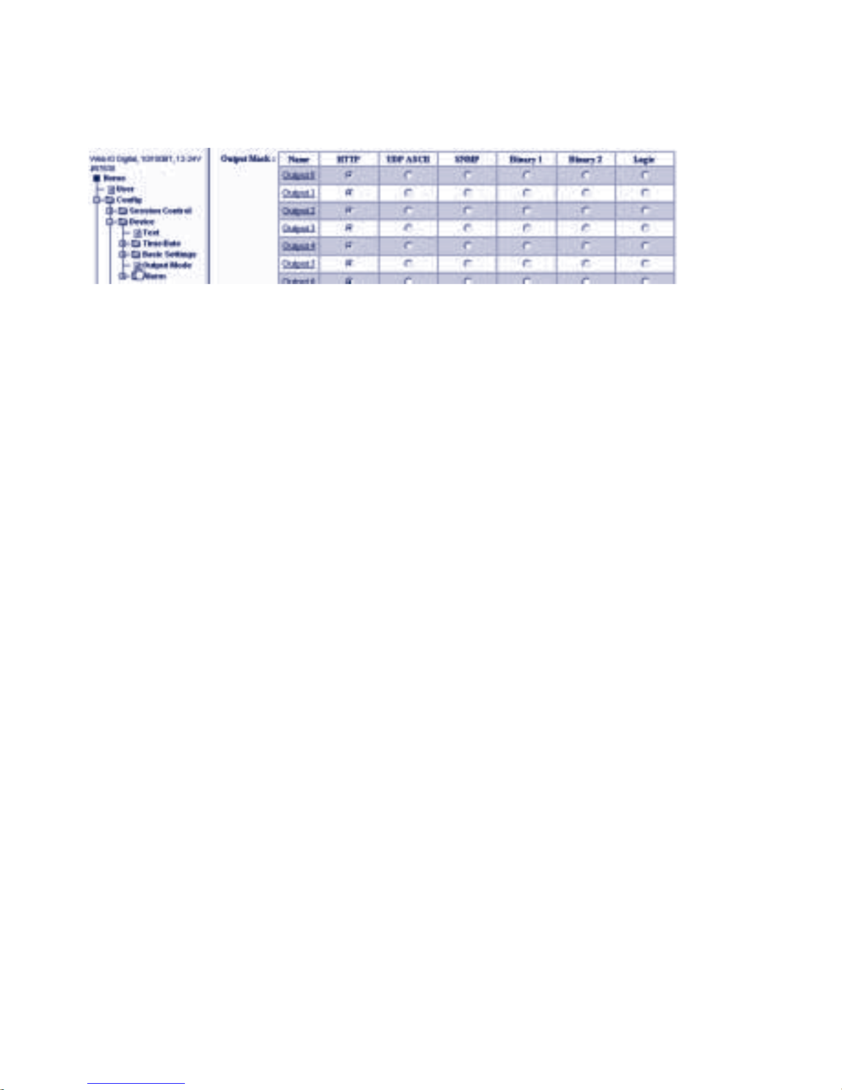
76
W&T Controlling the Web-IO with TCP/UDP Sockets
Select in the navigation tree Config >> Device >> Output Mode
m Required access rights: Administrator
All the outputs that will be used must be activated for HTTP
(factory default).
If you have changed the output modes, click on the Temporary
Storage button and then on the Save and activate all temporary
settings link. Clicking on the Save button saves all your settings.
The Web-IO now functions as a TCP server, which results in a
three-part program sequence regardless of which programming
language is used:
1. Opening of the TCP connection
The application always functions as a client and opens the TCP
connection.
The socket interface of the Web-IO is based to a great extent on
HTTP protocol. This means that the listen port is fixed as TCP-
Port 80.
1
As a protection against blocked TCP connections, the
Web-IO has a timer set for Port 80 which automatically
breaks the connection 30 seconds after it is opened if no
syntactically correct commands have been received. After a
connection has been successfully opened, the application should
therefore always send for example an output query to the Web-IO.
2. Communication between Web-IO and application
Normal communication takes place in polling mode. This means:
the client application uses the command strings to request the
desired values and set the outputs.
Page 77

77
W&T Controlling the Web-IO with TCP/UDP Sockets
Subject to errors and modifications:
Example 1: Query the status of Input 3, where there is a +12 V
signal present. No administrator password was assigned for the
Web-IO.
The application sends the following string to the Web-IO:
GET /input3?PW=&
The Web-IO responds as follows:
input3;ON
Example 2: Set outputs 3,4,7,9. In binary this is 0000 0010 1001
1000, which corresponds to 0298 hex.
The administrator password for the Web-IO is: „blue“
The application sends the following string to the Web-IO:
GET /outputaccess?PW=blue&State=0298&
The Web-IO responds as follows:
output;0298
1
The Web-IO works with null-terminated strings!
This means that everything the Web-IO sends to the
application ends with a chr(0) character
Event-driven messaging
Some applications make it necessary to report changes on
certain inputs automatically over the existing TCP connection.
One reason for this is to reduce the data load on the network. If
the inputs are polled at a cyclical interval, this will create a
continuous data load. There is also the risk that changes on
the inputs will not be detected if they occur between intervals.
To set the conditions for event-driven messaging, go to the
navigation tree and select Config >> Device >> Basic Settings
Page 78
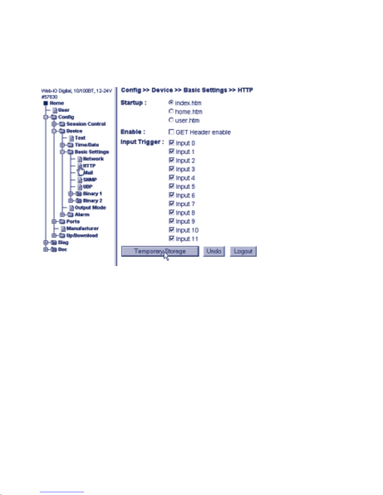
78
W&T Controlling the Web-IO with TCP/UDP Sockets
>> HTTP
m Required access rights: Administrator
Input Trigger
Here you specify which inputs are to be monitored for a state
change. If there is an existing connection, the Web-IO
automatically sends the new input state to the application.
Include a header
The Web-IO can if needed precede the sent string with a header
which contains the IP address and the name.
Example:
. The IP address of the Web-IO is 172.16.232.17.
. „W&T Web-IO 12xDigital“ was entered as the device name
under Config >> Device >> Text .
. The application polled the inuts using GET /input?PW=&.
The Web-IO returns:
Page 79

79
W&T Controlling the Web-IO with TCP/UDP Sockets
Subject to errors and modifications:
172.16.232.6;W&T Web-IO 12xDigital;input;0000
If GET Header enable was activated, the header precedes all data
transmission from the Web-IO.
If all conditions have been specified, activate the new setting
using Config >> Session Control >> LogOut.
Messaging with defined input patterns
In some applications it is practical to get the state of the inputs
only when certain input patterns occur.
i
The messaging method described here can be used in
tandem with normal event-triggered operation; in
practice however this does not offer any advantages, since in
this case there will be a message whenever there is a change.
This means you would receive double messaging whenever the
specified input pattern occurs.
To set the conditions for a TCP alarm message when certain
input patterns occur, go to the navigation tree and select
Config >> Device >> Alarm >> Alarm 1
m Required access rights: Administrator
Page 80
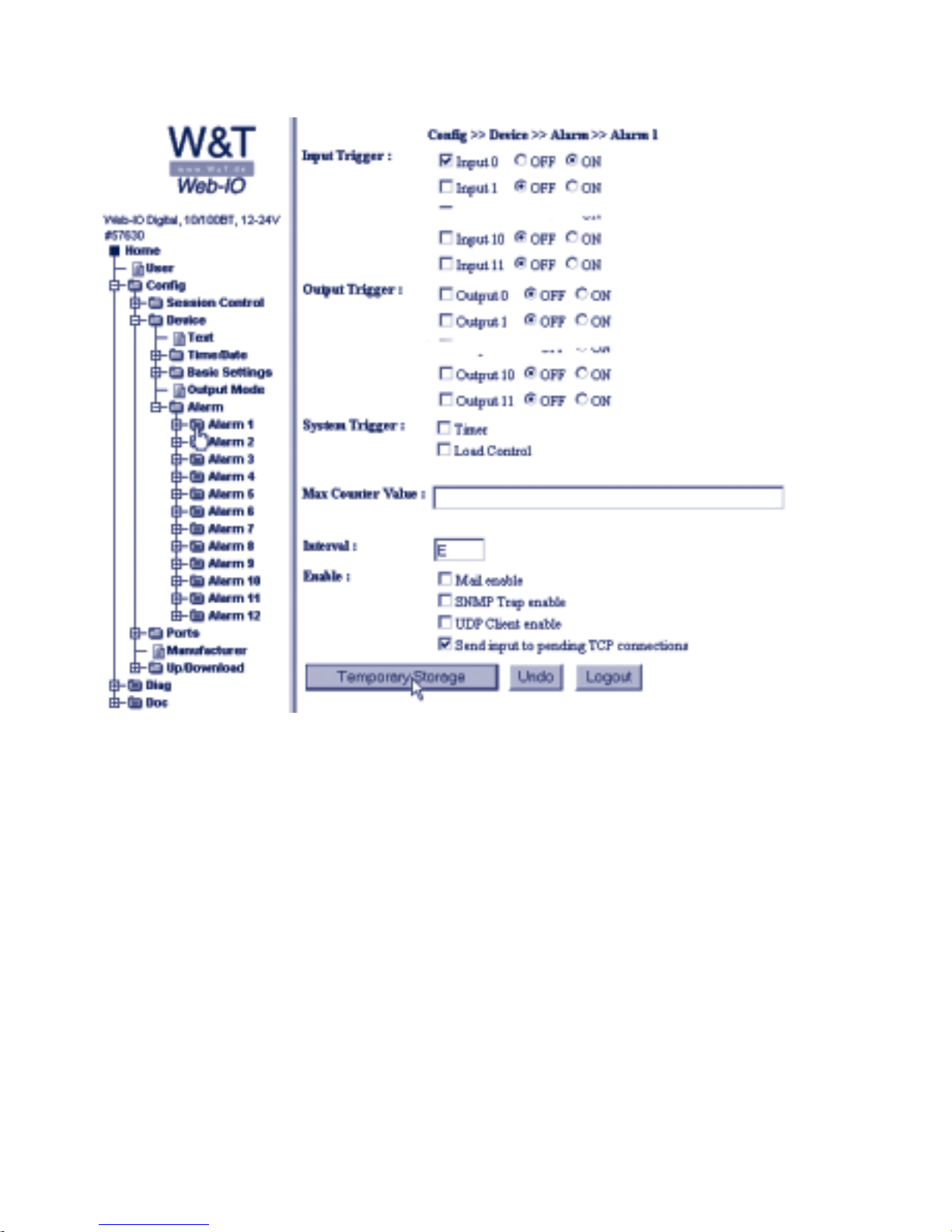
80
W&T Controlling the Web-IO with TCP/UDP Sockets
Input Trigger
Here you specify which inputs are to be monitored for which
state. If you are activating multiple inputs in an alarm for
monitoring, there is an AND-operation on the conditions.
Example:
In Alarm 1 Input 1 was activated for ON, Input 2 for OFF.
An alarm is only sent to the TCP application if both conditions
are met. In this case: Input 1= ON, Input 2 = OFF.
Interval
To send alarms over an existing TCP connection it is practical
to set the E parameter here so that only one alarm message is
sent when the alarm condition occurs.
Page 81

81
W&T Controlling the Web-IO with TCP/UDP Sockets
Subject to errors and modifications:
Enable
Activate the Send input to pending TCP connections in the
Enable area.
Pass the selected alarm conditions to the Web-IO by clicking
on the Temporary storage button.
When all the alarm conditions have been specified, activate the
new settings using Config >> Session Control >> LogOut
Clicking on the Save button restarts the Web-IO with the new
parameters.
3. Close the TCP connection
Here the Web-IO deviates from HTTP protocol. In contrast to
HTTP protocol, it is always the client application which closes a
connection.
1
Exception: When it receives a defective
command string, the Web-IO immediately closes the
connection
5.5.2 UDP communication
First you need to activate the Web-IO for communication via UDP
command strings and enter the local port.
Select in the navigation tree Config >> Basic Settings >> UDP
m Required access rights: Administrator
Page 82
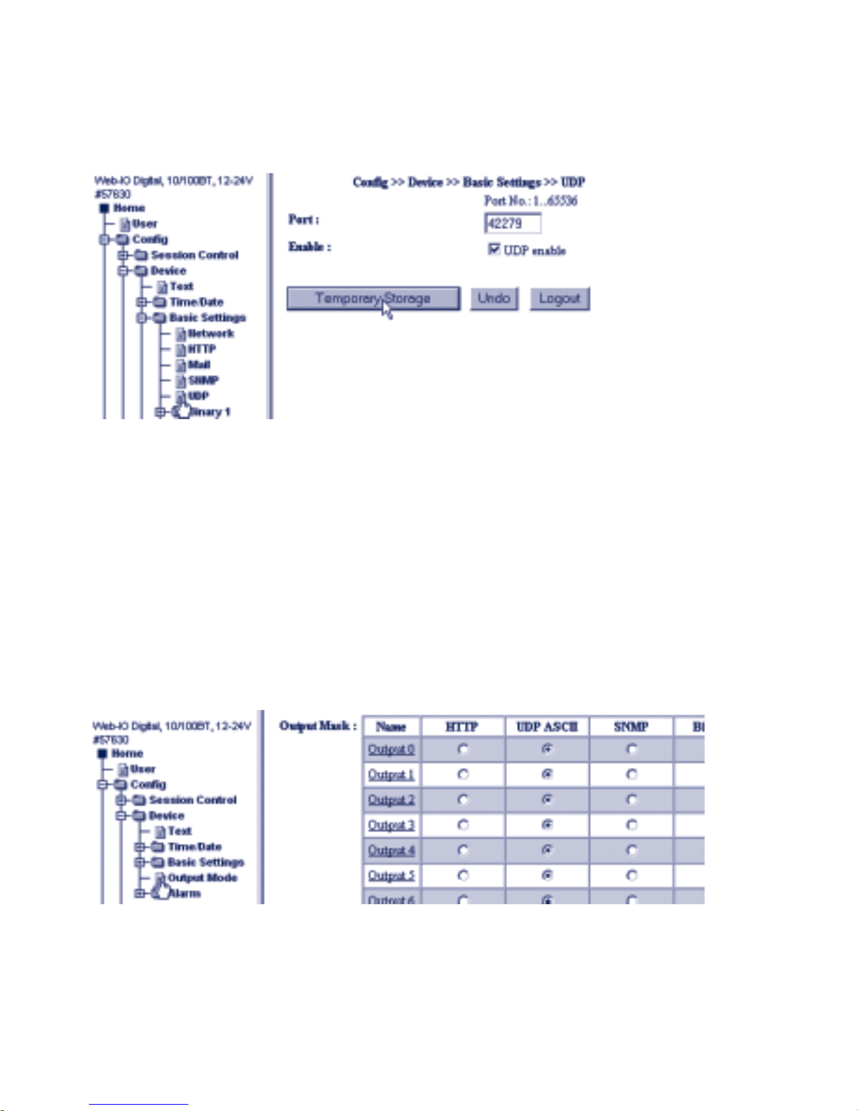
82
W&T Controlling the Web-IO with TCP/UDP Sockets
In the Port field enter the desired local port. The factory setting
is Port 42279. Check UDP enable.
Click on the Temporary Storage button to pass the selected
settings to the Web-IO.
You must also specify which of the 12 outputs you want to make
available for access via UDP using command strings.
Select in the navigation tree Config >> Device >> Output Mode.
m Required access rights: Administrator
All the outputs used must be activated for UDP ASCII.
If you have changed the output modes, click on the Temporary
Storage button and then on the Save and activate all temporary
settings link. Clicking on the Save button saves all your settings.
Page 83

83
W&T Controlling the Web-IO with TCP/UDP Sockets
Subject to errors and modifications:
Communication between Web-IO and the application
In contrast to TCP, there is no communication between the WebIO and the other communications partner when communicating via
UDP protocol. Data are exchanged using datagrams.
Normal communication takes place in polling mode. This means
the application uses command strings to request the desired
values and set the outputs.
The Web-IO always responds to a poll by returning the IP address
and port of the requesting network station.
Example 1: Query the status of Input 3, where there is a signal of
+12 V present. No administrator password was asigned for the
Web-IO
The application sends the following string to the Web-IO:
GET /input3?PW=&
The Web-IO responds as follows:
input3;ON
Example 2: Set outputs 3,4,7,9. In binary this is 0000 0010 1001
1000 , which corresponds to 0298 hex.
The administrator password for the Web-IO is: „blue“
The application sends the following string to the Web-IO:
GET /outputaccess?PW=blue&State=0298&
The Web-IO responds as follows:
output;0298
1
The Web-IO works with null-terminated strings!
This means that everything the Web-IO sends to the
application ends with a chr(0) character
Page 84
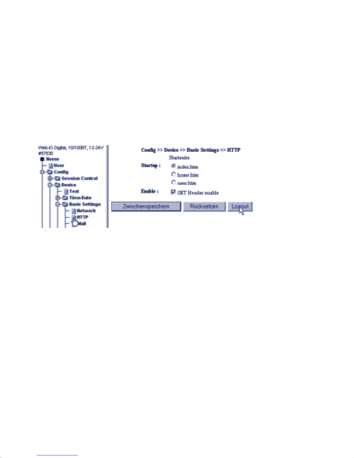
84
W&T Controlling the Web-IO with TCP/UDP Sockets
So that under UDP a message can be automatically received
when states change, the Web-IO provides a variety of various
alarm conditions.
i
A detailed description of how to use these alarm
possibilities can be found in the Alarms section
Include a header
The Web-IO can if needed precede the sent string with a header
containing the IP address and the name.
To enable a header, go to Config >> Basic Settings >> HTTP and
select GET Header enable. Clicking on Logout and Save
activates sending of the header.
Example:
. The IP address of the Web-IO is 172.16.232.17.
. „W&T Web-IO 12xDigital“ was entered as the device name
under Config >> Device >> Text „“.
. GET /input?PW=& was used by the application to poll the
inputs.
The Web-IO returns:
172.16.232.6;W&T Web-IO 12xDigital;input;0000
If GET Header enable was activated, the header precedes all data
sent by the Web-IO.
Page 85

85
W&T Controlling the Web-IO with TCP/UDP Sockets
Subject to errors and modifications:
5.5.3 Program-controlled error management
If the Web-IO detects one or more errors while processing its
tasks, these are saved and are viewable from the navigation tree
under Diag.
A more detailed description of this can be found in Section 6.6
Diagnostics and Testing.
In some applications it may be desired that error management
is handled not manually by viewing a Web page, but rather
errors are automatically evaluated in a program.
For such cases the Web-IO provides several command strings
for using TCP or UDP.
Creating a list pf possible error messages
The Web-IO can manage a maximum of 64 different error types.
The actual number may vary within this limit depending on the
firmware version.
To get an overview of the possible errors, the command
GET /diaglistx?PW=password&
can be sent to the Web-IO.
x is replaced by a value between 0 and 64. INstead of password
enter the Administrator or Operator password.
The Web-IO replies with the corresponding error message.
diaglistx;errortext
Example:
If the application sends (Passwort = „wut“) to the Web-IO
GET /diaglist2?PW=wut&
Page 86

86
W&T Controlling the Web-IO with TCP/UDP Sockets
the Web-IO responds with
diaglist2;Formatfehler in der DNS Anfrage
With a for next loop the diaglist command can be used to read
out all possible error messages and save them as a static list.
In binary mode, for example, you can only determine how many
errors there are currently. The associated error numbers are also
sent. By using the static error list a readable error can be
output.
Direct evaluation of the current errors
To get the current error status of the Web-IO you can use the
command
GET /diagnosis?PW=password&
The Web-IO responds with
diagnosis;zzzz;yyyyyyyy;xxxxxxxx
In zzzz the Web-IO returns the number of current errors in 4place hex format.
yyyyyyyy; xxxxxxxx may be ignored for normal, standard
applications.
For expert programmers: yyyyyyyy; xxxxxxxx are two 32-bit
values, each in 8-place hex format. THe resulting 64 bits
substitute for the 64 possible error types. By using the static
error list (see GET /diaglist...) the individual bits can be
decoded. The LSB appears to the right in the x range and the
MSB to the left in the y range.
To get the current errors as an error text, the Web-IO provides
the command
GET /diagnosisx?PW=&
Here x is the index for the error in decimal format beginning
with 1.
Page 87

87
W&T Controlling the Web-IO with TCP/UDP Sockets
Subject to errors and modifications:
The reply from the Web-IO then looks as follows:
diagnosisx;errortext
In contrast to the error texts which are read from the Web-IO
using diaglist, the error text for diagnosis may also contain
dynamic elements such as IP addresses or port numbers.
Example:
The application sends:
GET /diagnosis?PW=wut&
The Web-IO responds:
diagnosis;0005;00400040;008A0000
The application sends:
GET /diagnosis1?PW=wut&
The Web-IO responds:
diagnosis1;Mail Server antwortet nicht.
The application sends:
GET /diagnosis2?PW=wut&
The Web-IO responds:
diagnosis2;Das Versenden der Mail wurde abgebrochen und wird wiederholt.
The application sends:
GET /diagnosis3?PW=wut&
The Web-IO responds:
diagnosis3;Ziel IP-Adresse unbekannt: 172.16.232.8.
Page 88

88
W&T Controlling the Web-IO with TCP/UDP Sockets
The application sends:
GET /diagnosis4?PW=wut&
The Web-IO responds:
diagnosis4;Watchdog Timer abgelaufen!
The application sends:
GET /diagnosis5?PW=wut&
The Web-IO responds:
diagnosis5;TCP Client Alarm: Server nicht erreicht.
Clearing the error memory
The list of errors occuring during runtime remains stored in the
Web-IO, even if the error is no longer present at the time of
query.
To clear the error memory, use the command
GET /diagclear?PW=password&
The Web-IO responds with
diagnosis;0000;00000000;00000000
if there are no current errors.
Special handling of overload errors (TCP only)
The Web-IO can continuously monitor for the load on the
outputs. If the maximum output current is exceeded, the
corresponding output is turned off as long as the overload is
present.
The menu item Config >> Device >> Outputmode can also be
used to activate continuous turnoff of the outputs. To do this,
activate Load Control enable.
Page 89
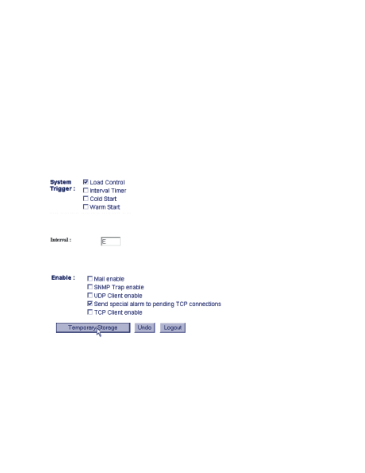
89
W&T Controlling the Web-IO with TCP/UDP Sockets
Subject to errors and modifications:
In case of overload the affected output is completely turned off
an must be enabled again by the user.
See also Section 6.6 Diagnostics and Testing.
To automatically process overload errors from the application
program, it is possible to define a corresponding alarm which
sends an error message to the program when a TCP connection
is open.
Select Config >> Device >> Alarm >> Alarm1
Activate Load Control under System Trigger.
Enter E as an interval (= one-time).
Under Enable check
and click on Intermediate Storage.
Once all entries pertaining to the alarm have been made,
activate the new settings under Config >> Session
Control >> LogOut, Save.
Now if an overload condition arises, the Web-IO sends the
following to the application over the open TCP connection:
Page 90

90
W&T Controlling the Web-IO with TCP/UDP Sockets
error;xxxx
where xxxx is the hex value for the output which was turned
off.
Example:
error;0001
In this case Output 0 is affected.
To turn on the affected outputs again, the application program
sends
GET /errorclear?PW=password&
to the Web-IO.
Now if there is no longer an overload condition, the Web-IO
resumes as normal on all outputs.
1
Please note that the GET HEADER ENABLE setting under
Config >> Device Basic Settings >> HTTP also precedes
the Error and Diag messages with a header. The 0 character is
still appended for error messages.
Page 91

91
W&T TCP / UDP - Binary
Subject to errors and modifications:
5.6 BINARY - socket programs with binary structures
The Web-IO 12 X Digital provides two independent socket
accesses, Binary 1 and Binary 2, for carrying out binary data
exchange. Both can be used and configured independently of each
other.
Whether the Web-IO functions on the respective BINARY socket
as a TCP server, TCP client or UDP peer depends on the desired
application.
First an overview of which operation mode the Web-IO uses for
which application.
. Your own socket application (binary with password
protection)
. TCP-Server
. TCP-Client
. UDP-Peer
. Your own socket application, which was originally programmed
for the W&T Digital I/O Com-Server 50xxx.
. TCP-Server
. TCP-Client
. UDP-Peer
. Box-to-Box Master
. TCP-Client
. Box-to-Box Slave
. TCP-Server
. OPC-Device together with the W&T OPC-Server
. TCP-Server
Binary socket access and 50xxx-Mode
In this section you will be shown how the Web-IO 12XDigital can
be accessed from your own professional applications using
sockets with binary structures.
Page 92
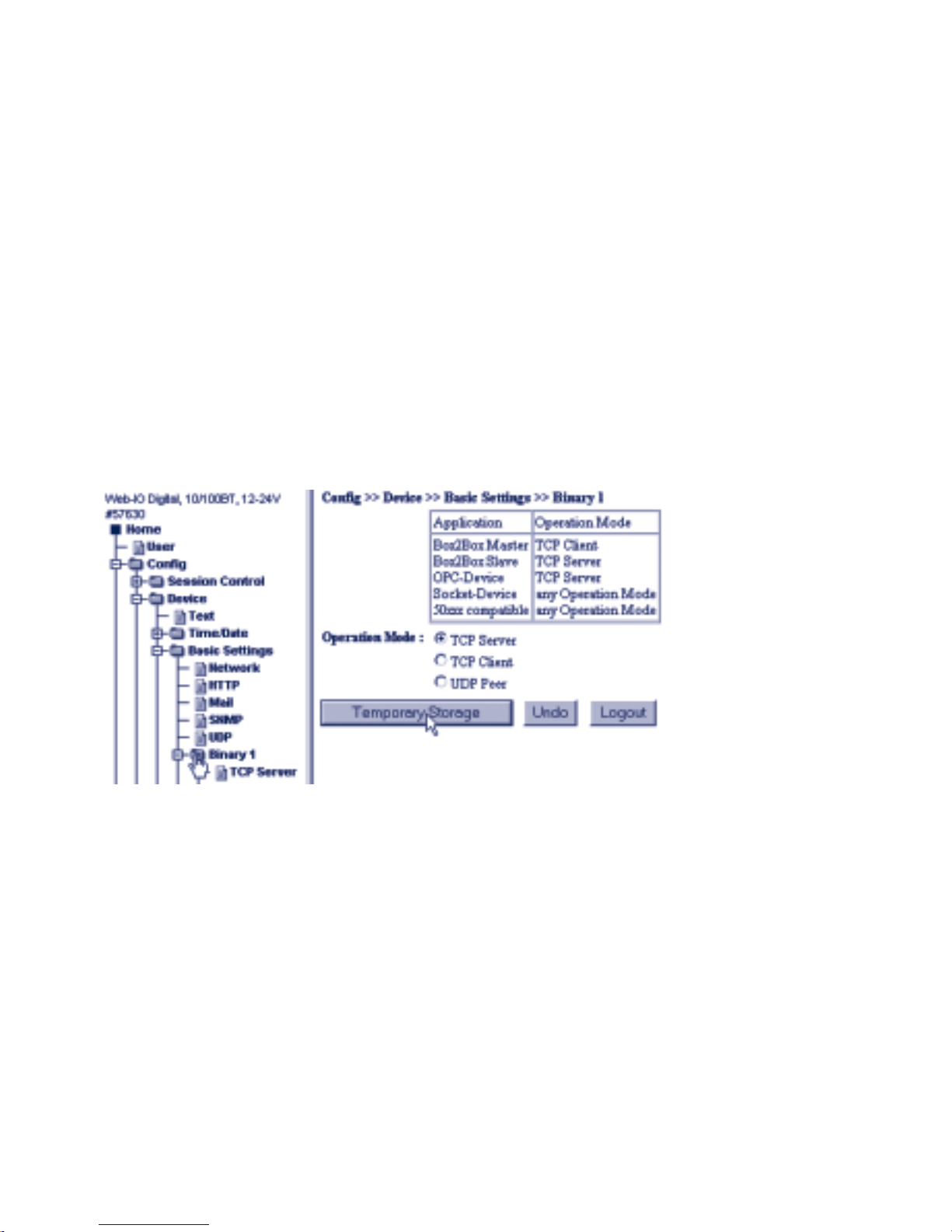
92
W&T TCP / UDP - Binary
i
Box-to-box and OPC device modes will be treated in
detail in the following sections
5.6.1 Specifying the operation mode
First you must specify whether the Web-IO is to be a TCP client,
TCP server or UDP peer in your application.
Select in the navigation tree Config >> Device >> Basic Settings
>> Binary 1 if you want to configure the operation mode for access
through Binary 1.
m Required access rights: Administrator
After selecting the desired mode, pass the setting to the Web-IO
by clicking on Temporary Storage.
Two levels of socket programming are available to the programmer
for access from your own application programs.
1. Password protected access
2. 50xxx-Mode compatible with the older W&T Digital I/O
Com-Servers
Both levels work with the same binary structures and differ only in
the lack of password protection in 50xxx mode.
Page 93
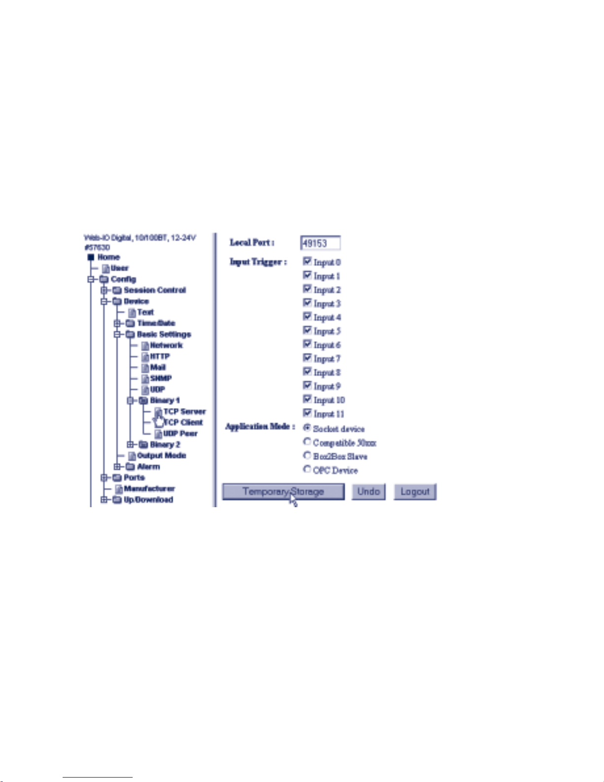
93
W&T TCP / UDP - Binary
Subject to errors and modifications:
5.6.2 The Web-IO as socket server
To operate the Web-IO as a socket server, you must make a few
additional settings.
Select in the navigation tree Config >> Device >> Basic Settings
>> Binary 1>> TCP Server
m Required access rights: Administrator
Local Port
The local port of the Web-IO is factory set for 49153. If your
application requires a different local port for the Web-IO, enter the
desired port number in the Local Port field.
Input Trigger
Here you check the inputs whose state change will trigger data to
be sent to the client application (important for event-triggered
applications).
Application Mode
Select here:
Page 94

94
W&T TCP / UDP - Binary
. Default - If you want access to the Web-IO to be password
protected.
. Compatible 50xxx - If you want to access applications that
were programmed for the older Digital I/O Com-Servers. You
can also use this mode for new applications that do not require
password protection.
i
Additional information concerning Box2Box Slave and
OPC Device modes can be found in the corresponding
sections.
Once you have made all your settings, send them to the WebIO by clicking on the Temporary Storage button.
In addition you must enable the corresponding outputs for binary
mode.
Under Config >> Device >> Output Mode select the desired bnary
access.
m Required access rights: Administrator
Once you have made all your settings, send them to the Web-IO
by clicking on the Logout button. Clicking on the Save button
activates the settings.
i
All the configuration possibilities shown for Binary 1
can also be used for Binary 2.
5.6.3 The Web-IO as socket client
To operate the Web-IO as a socket client, you must make a few
additional settings.
Page 95
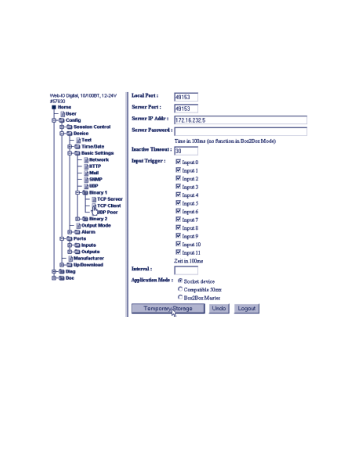
95
W&T TCP / UDP - Binary
Subject to errors and modifications:
Select in the navigation tree Config >> Device >> Basic Settings
>> Binary 1>> TCP Client
m Required access rights: Administrator
Local Port
The local port of the Web-IO is factory set for 49153. If your
application requires a different local port for the Web-IO, enter the
desired port number in the Local Port field.
Server Port
Enter here the port number which the server application will use to
accept the connection.
Server IP Addr
Enter here the IP address of the server.
Page 96

96
W&T TCP / UDP - Binary
Server Password
A server password only needs to be entered if you want the WebIO to work as a box-to-box master or access an additional Web-IO
as a TCP client in server mode. See Box-to-Box section.
Inactive Timeout
Here you configure the timer used by the Web-IO to close the
connection after the time has expired. Enter the value in decimal
using 100ms increments. When there is an active network
connection the timer is reset once all the data have been
exchanged.
Example: The value 10 corresponds to one second. If no data
transfer is detected during this time, the Web-IO closes the
connection.
Entering no value means automatic connection closing is
deactivated.
Input Trigger
Check the inputs whose state change you want to use as triggers
for opening the TCP connection and sending data to the server
(important for event-triggered applications).
Interval
If you want to cyclically notify the server application of input state
changes, enter the interval here in (value will be multiplied with
100ms) .
Example: The value 300 corresponds to 30 seconds.
1
Please note that when using charged dial-up
connections, too short an interval can result in this
connection remaining open while charges continue to
accumulate!
Mode
Select here:
. Default - If you want access to the Web-IO to be password
protected.
Page 97
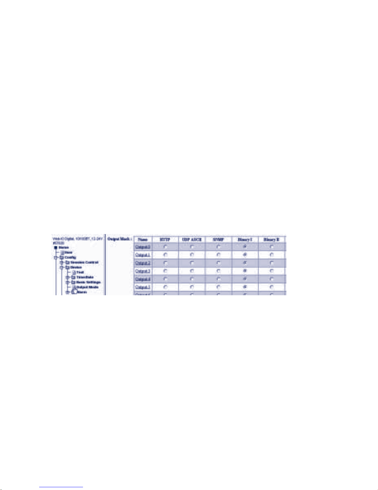
97
W&T TCP / UDP - Binary
Subject to errors and modifications:
. Compatible 50xxx - If you want to access applications that
were programmed for the older Digital I/O Com-Servers. You
can also use this mode for new applications that do not
require password protection.
Additional information about Box2Box Master can be found in the
section Box-to-Box.
Once you have made all your settings, send them to the WebIO by clicking on Temporary Storage.
In addition you must enable the outputs you want to use for
binary mode.
Under Config >> Device >> Output Mode check the desired
binary access.
m Required access rights: Administrator
Once you have made all your entries, send them to the Web-IO by
clicking on the Temporary Storage button.. Clicking on the Save
button activates the settings.
5.6.4 The Web-IO as UDP Peer
To operate the Web-IO as a UDP peer, you must make a few
additional settings.
Select in the navigation tree Config >> Device >> Basic Settings
>> Binary 1>> UDP Peer
m Required access rights: Administrator
Page 98
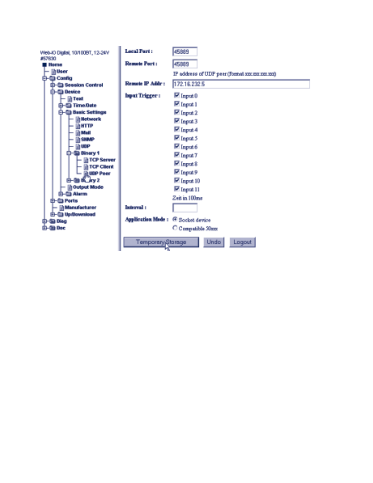
98
W&T TCP / UDP - Binary
Local Port
The local port of the Web-IO is factory set for 45889. If your
application requires a different local port for the Web-IO, enter the
desired port number in the Local Port field.
Remote Port
Enter here the port number the UDP application communicating
with the Web-IO will use to receive data.
Remote IP Addr
Enter here the IP address of the communications partner.
Input Trigger
Check here the inputs whose state change will be used as a trigger
for sending a UDP datagram (important for event-triggered
applications).
Page 99

99
W&T TCP / UDP - Binary
Subject to errors and modifications:
Interval
If you want to send the state of the inputs cyclically to the
communications partner, the interval can be entered here in 100ms
increments.
Example: The value 300 corresponds to 30 seconds.
1
Please note that when using charged dial-up
connections, too short an interval can result in this
connection remaining open while charges continue to
accumulate!
Application Mode
In UDP peer configuration, there is no difference between the
Default and Compatible 50xxx modes.
Once you have made all your settings, send them to the Web-IO
by clicking on the Temporary Storage button.
In addition you must enable the corresponding inputs for binary
mode.
Under Config >> Device >> Output Mode select the desired binary
access.
m Required access rights: Administrator
Once you have made all your entries, send the setting to the
Web-IO by cliking on the Logout button. Clicking on the Save
button activates the settings.
Page 100

100
W&T TCP / UDP - Binary
5.6.5 Passwort protection
As already mentioned several times, the Web-IO in TCP server
mmode makes it possible to protect access to the application
by means of a password..
Before the actual connection to the Web-IO is opened, the
BIN_INFO structure defined here must be sent to Port 80 of the
Web-IO over a separate TCP connection.
The Web-IO also uses the BIN_INFO structure for its reply.
BinInfo BYTE[n] HTTPlogin n = 14 Byte + Password
(PC <-> Web-IO) WORD dummy always 0
BYTE type type of request
BYTE subtype additional type information
LONG srcip source IP address
WORD srcport source port
WORD destport detination port
The individual variables of the structure are filled as follows::
HTTPLogin[n]
Is a byte field or string consisting of a login string and the
administrator password..
GET /bin?LPW=
<Administator Passwort>
&
n stands for the number of bytes used and corresponds to 14
+ the length of the password. The length of the password is
restricted to max. 31 characters.
In the reply from the Web-IO HTTPLogin is always 8 characters
long and contains the following string::
GET /bin
Dummy
Separator between the ASCII and binary part of the structure..
is always = 0x00
 Loading...