

W&T 57601, 57604, 57603 User Manual

W&T
Manual
Web-IO 1x Thermometer
Web-IO 2x Thermometer
Web-IO 8x Thermometer
Type 10/100BaseT, 12-24V
Model 57601, 57603, 57604
Release 1.13, Nov. 2003
US 1.13 11/2003 ML

W&T
2
© 10/2002 by Wiesemann & Theis GmbH
© 11/2003 by Wiesemann & Theis GmbH
Subject to errors and modifications:
Since we can make mistakes, do our statements should not be
applied without verification. Please bring any errors or misunderstandings to our attention, so that we can recognize and
correct them as soon as possible.
Perform work on and with W&T products only as described here
and after you have fully read and understood the manual. Unauthorized actions may result in hazardous conditions. We are
not liable for unauthorized use. If in doubt, please check with
us or your dealer!
W&T
Subject to errors and modifications
3
Introduction
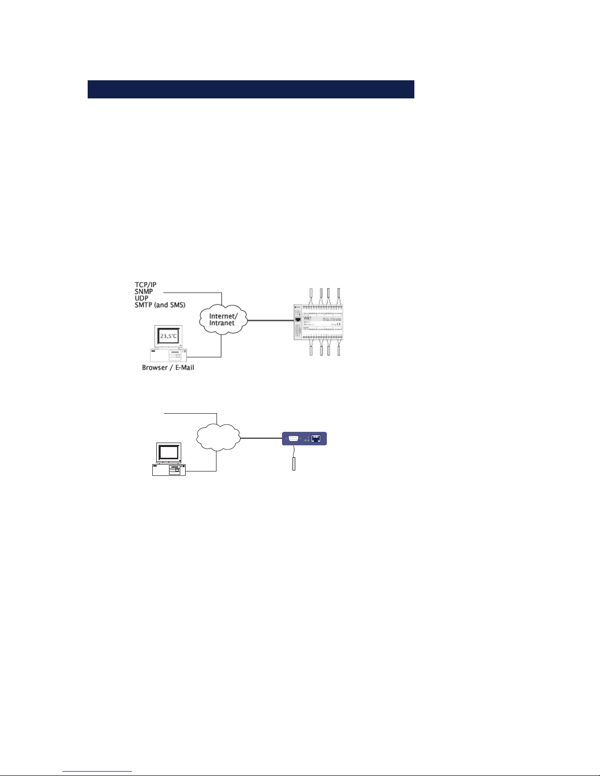
The Web-IO thermometer allows you to remotely monitor
temperatures and temperature trends via Internet browser or e-Mail. You can create your own HTML pages for visualizing the temperatures and generate personal information in order to be kept informed of current temperatures.
This manual contains all the information you will need to
install, configure and operate the Web-IO Thermometer.
Internet/
Intranet
23,5°C
Browser / E-Mail
TCP/IP
SNMP
UDP
SMTP (auch SMS)
Serial Port
Power
Network
Status
Error

W&T
4
Contents
Introduction ............................................................................................ 3
1 Connections and Displays ............................................................. 6
1.1 Ethernet connection ........................................................ 6
1.2 Connecting the probe to the
Web-IO 1x Thermometer .................................................. 7
1.3 Connecting the probes to the
Web-IO 2x/8 Thermometer ............................................... 8
1.4 Supply voltage for the Web-IO 1x Thermometer ............... 10
1.5 Supply voltage for the Web-IO 2x/8x Thermometer ......... 10
1.6 LED displays ................................................................. 10
2 TCP/IP Configuration....................................................................13
2.1 Assigning the IP address ... ............................................ 13
2.1.1 ... using WuTility ................................................... 13
2.1.2 ... using DHCP-/BOOTP protocol ............................. 14
2.1.3 ... using ARP command .......................................... 16
2.1.4 ... over the serial interface ...................................... 17
2.1.5 ... using an RARP server (UNIX only) ........................ 18
2.2 Setting the subnet mask and gateway ............................. 19
2.3 Connecting the Web-IO 8x Thermometer ........................ 20
3 Configuring the Web-IO 8x Thermometer .............................21
3.1 Administration .............................................................. 22
3.1.1 LogOut ................................................................ 23
3.1.2 New Password ....................................................... 24
3.2 Configuration ............................................................... 25
3.2.1 Network ................................................................ 26
3.2.2 Text ..................................................................... 26
3.2.3 Time/Date ............................................................ 26
3.2.4 Time Zone ............................................................ 26
3.2.5 Time Server ........................................................... 27
3.2.6 Device Clock ......................................................... 28
3.2.7 Mail ...................................................................... 29
3.2.8 Alarm 1..8 ............................................................. 30

W&T
Subject to errors and modifications
5
3.2.9 Data Logger ......................................................... 33
3.2.10 Memory .............................................................. 33
3.2.11 Protocol ............................................................. 33
3.2.12 Enable ................................................................ 34
3.2.13 Startup ............................................................... 35
3.2.14 Ports .................................................................. 36
3.2.15 Manufacturer ...................................................... 36
3.2.16 Up-/Download .................................................... 36
3.2.17 Diag ................................................................... 38
4 Single temperature polling... .....................................................39
4.1 ... via TCP/IP ..................................................................39
4.2 ... via UDP ..................................................................... 40
4.3 ... via SNMP ................................................................... 40
5 Incorporating the temperature into your own Web Site .... 41
6 Data Logger .......................................................................................43
7 Appendix ............................................................................................ 44
7.1 Calibration ................................................................... 44
7.2 Firmware Update ........................................................... 45
7.2.1 Where can I get the latest firmware? ........................ 45
7.2.2 Firmware update over the network under Windows ... 45
7.3 Emergency access ......................................................... 47
7.4 Extending the NTC cable ............................................... 47
7.5 Example of an XML configuration ................................... 49
7.6 Example for setting the „user.htm“ ................................. 63
7.7 Technical specifications ................................................ 70

W&T
6
1.1 Ethernet connection
The network connection is provided in the form of an IEEE-8023-compatible terminal on a shielded RSJ45 plug located on the
front of the unit. Here the Web-IO 8x Thermometer can be connected to a hub or switch. The pin configuration corresponds
to a standard MDI interface (AT&T258), so that a 1:1 cable with
a length of maximum 100 meters can be used.
10BaseT, 10MBit/s or autosensing 100BaseT, 100/10MBit/s are
supported:
Please note that all plugs must be connected and disconnected only with the terminal devices are turned off.
!
Be sure that the network cable for the Web-IO does not
exceed a maximum permissible length of 100m.
1 Connections and Displays
1 = Tx+
2 = Tx-
3 = Rx+
4 = nc 5 = nc
6 = Rx-
7 = nc
8 = nc
RJ45 female (AT&T256 standard)
W&T
Subject to errors and modifications
7
The Error LED on the front panel indicates the current link status: If it flashes at 1-2 second intervals, there is no connection
to the hub or the connection is faulty.
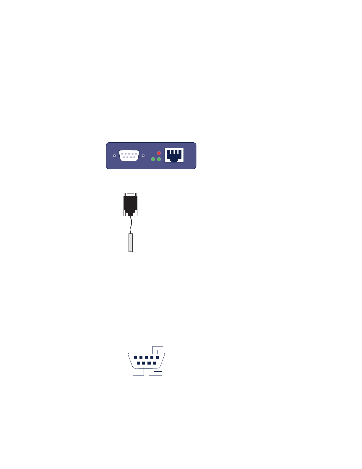
1.2 Connecting the probe to the Web-IO
1x Thermometer
Connecting the NTC probe
U
The supplied NTC probe is already preconfigured and is simply
plugged into the DB9 connector in the device.
Connecting a PT100 probe
If you want to connect a PT100 probe, the pin configuration is
as follows:
Serial Port
Power
Network
Status
Error
RS232
1 = NTC 5 = PT100(weiß)
4 = NTC
8 = PT100(rot)
9 = PT100(rot)
7 = PT100
(weiß)
W&T
8
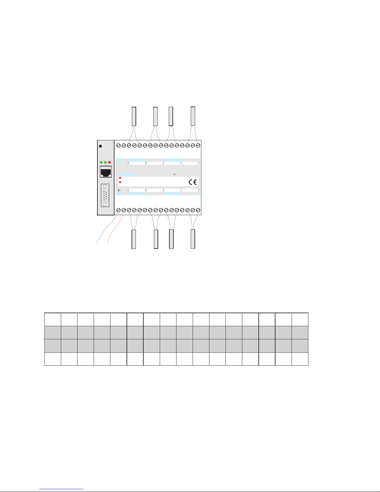
1.3 Connecting the probes to the Web-IO 2x/8
Thermometer
Connecting the NTC temperature sensors
The eight NTC temperature sensors are connected to the unit
as shown in the following table. The numbering corresponds
to the screw terminals on the unit:
For information on extending the NTC cable, see Appendix
(7.4).
5CTN5CTN6CTN6CTN7CTN7CTN8CTN8CTN
71 81 91 02 12 22 32 42 52 62 72 82 92 03 13 23
1 2 3 4 5 6 7 8 9 01 11 21 31 41 51 61
1CTN1CTN2CTN2CTN3CTN3CTN4CTN4CTN
n.c.
1 2 1.RV 1.R+ 1.R- RG 2.R- 2.R+ 2.RV 3.RV 3.R+ 3.R- RG 4.R- 4.R+ 4.RV
5.RV 5.R+ 5.R- RG 6.R- 6.R+ 6.RV 7.RV 7.R+ 7.R- RG 8.R- 8.R+ 8.RVn.c.
http:// . . . /diag
on
error
Web-IO
8xThermometer
10/100BT, 12-24V, #57604
W&T
www.wut.de
12-24V
1
23
4
5678
9
10 11 12 13
14 15
16
17 18 19
20 21 22 23 24 25 26 28 29 30
31
32
27
Reset
Power
Status
Error
Serial Port
12-24V AC/DC
NTC1
NTC2
NTC3
NTC4
NTC5
NTC6
NTC7
NTC8
system error
W&T
Subject to errors and modifications
9
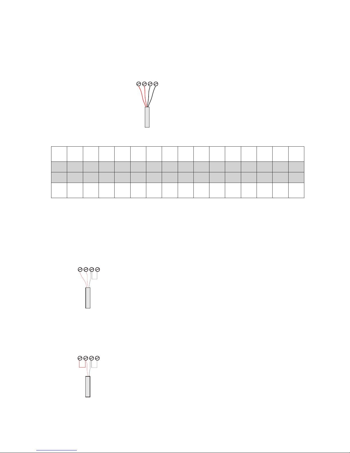
Connecting the PT100 temperature sensors
The cable for the PT100 4-wire temperature sensor may be routed over any desired length.
Connecting a PT100 3-wire sensor:
001TP
5
der
001TP
5
der
001TP
5
etihw
001TP
6.u5
etihw
001TP
6
etihw
001TP
6
der
001TP
6
der
001TP
7
der
001TP
7
der
001TP
7
etihw
001TP
8.u7
etihw
001TP
8
etihw
001TP
8
der
001TP
8
der
71 81 91 02 12 22 32 42 52 62 72 82 92 03 13 23
1 2 3 4 5 6 7 8 9 01 11 21 31 41 51 61
001TP
1
der
001TP
1
der
001TP
1
etihw
001TP
2.u1
etihw
001TP
2
etihw
001TP
2
der
001TP
2
der
001TP
3
der
001TP
3
der
001TP
3
etihw
001TP
4.u3
etihw
001TP
4
etihw
001TP
4
der
001TP
4
der
The corresponding wires of the PT100 3wire sensor have to be connected to the
screw terminals R+ and RV. Connect the
seperate wire to the screw terminal R- and
attach a bridge to GND.
Connect one wire of the PT100 2-wire sensor to the screw terminal R+ and the other
wire to the screw terminal R-. Add a bridge
from R- to GND and one from R+ to RV.
Connecting a PT100 2-wire sensor:
3
4
56
PT100
red red white white
3
4
56
PT100 2-wire
3
4
56
PT100 3-wire
W&T
10
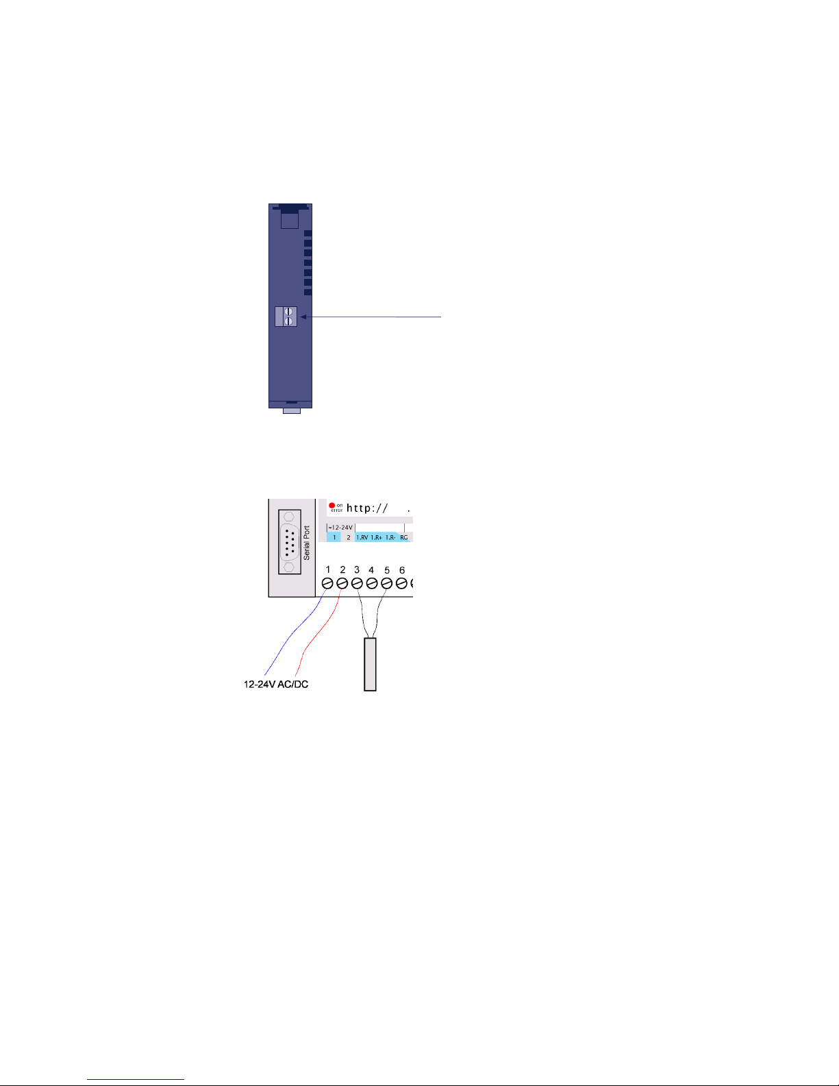
1.4 Supply voltage for the Web-IO 1x Thermometer
1.5 Supply voltage for the Web-IO 2x/8x Thermometer
The 12-24V AC/DC supply voltage is brought to the unit on
pins 1 and 2 located on the lower screw terminal block.
1.6 LED displays
■ Power-LED: Indicates the presence of supply voltage. If the
LED is not on, please check whether the power supply is
properly connected.
■ Status-LED: Flashes whenever there is network activity with
the Web Thermometer. Periodic blinking indicates that the
port has a connnection to another station.
Bottom 57601
supply
voltage
12-24V =/~
screw terminal

W&T
Subject to errors and modifications
11
■ Error-LED: The Error-LED uses various blink codes to indi-
cate fault conditions on the device or the serial port.
Error-LED blinks 1x = Check network connection.
The Web-IO 8x Thermometer is not receiving a link pulse
from a hub or switch. Check the cable or the hub/switch port.
Error-LED blinks 2x or 3x
Perform a reset by disconnecting the supply voltage or pres
sing the reset button. If the error is not cleared,
reset the unit to the factory defaults. Since this resets all net
work settings, you should first write them down.
Config -> Session Control -> LogOut ->
Restore Defaults
After a reset the device is restored to its factory default set-
tings. Make your network settings again as necessary. For
more information on menu guided configuration, see section 3. and following.
Power-LED + Status-LED + Error LED on = selftest failure
The self-test, which is performed after each start or reset of the
Web-IO 8x Thermometer, could not be correcly finished due to
an incomplete firmware update. The device is no longer operational in this state. Please return the unit.

W&T
12
Supplementary LED (for internal Web-IO 1x Thermometer)
■ on error http://xxx.xxx.xxx.xxx/diag -LED: Indicates in-
ternal configuration errors. For error diagnostics, open page
http://xxx.xxx.xxx.xxx/diag in the unit.
■ system error: Critical hardware error. Try to restart the unit
by interrupting supply voltage. If the condition persists, please return the unit for evaluation.
!
If the Web-IO Thermometer has no IP-address or the
address 0.0.0.0 the LEDs on error and system error stay
on after a reset or restart! The Web-IO 1x Thermometer
starts blinking for three times after a short time. After assigning a IP-address the LEDs will go off.

W&T
Subject to errors and modifications
13
2 TCP/IP Configuration
Once the hardware has been configured as described above,
the IP address necessary for operating in a TCP/IP network
must be assigned. Please request the correct value for this parameter from your system administrator.
!
The IP address must be unique throughout the network.
2.1 Assigning the IP address ...
There are five ways to first assign the IP address for the Web-IO
8x Thermometer:
2.1.1 ... using WuTility
First download the „WuTility“ tool from the WuT Homepage:
(http://www.wut.de)
Be sure that the PC you are using to assign the IP address is in
the same subnetwork as the device and that both the PC and
the device are connected to the network.
- Start „WuTility“ and click on the scan icon:
- Select your Web-IO Thermometer from the displayed list using
the MAC address:

W&T
14
2.1.2 ... using DHCP-/BOOTP protocol
Many networks use DHCP (Dynamic Host Configuration Protocol) or BOOTP for centralized and dynamic assignment of the
IP addresses. Which of the two protocols are used makes not
difference to the Web-IO devices, since DHCP is simply a downward compatible extension of BOOTP. DHCP servers thus also
use the requirements of BOOTP clients.
The MAC address is found on the label affixed to the housing:
- Click on the „Assign IP Address“ symbol:
- In the resulting window,k enter the desired IP address for the
device and confirm with „OK“: :
The device acknowledges the entry with an audible tone (2x/
8x Thermometer only) and accepts the set IP address. After
clicking again on the Scan button, this address is displayed in
the WuTility.
5xxxx [Typ]
EN=00c03d004a05
OK xxxxxx
Ethernet-address

W&T
Subject to errors and modifications
15
The following parameters can be assigned to the Web-IO 8x
Thermometer using these protocols:
■ IP address
■ Subnet mask
■ Gateway address
It is not possible to assign other parameters or a lease time.
Functionality
To obtain an IP address, the device sends after every new start
a corresponding BOOTP request as a broadcast to the network.
The resulting reply generated by the DHCP/BOOTP server contains in addition to the IP address the subnet mask and gateway address. The Web-IO 8x Thermometer immediately places
this information in its non-volatile memory.
When placing the unit into service in DHCP/BOOTP networks,
please consult with your system administrator. If DHCP will be
used for assigning the address, you must mention that a reserved IP address is required. To maintain the respective address
database, the administrator needs the Ethernet address of the
Web-IO 8x Thermometer, which can be found on the sticker on
the housing.
Once the necessary entries have been made, the device automatically obtains the desired IP address after each reset. To ensure that the Web-IO 8x Thermometer can also be reached if
the DHCP/BOOTP server fails, the previous IP address is retained if no reply follows.

W&T
16
!
In DHCP environments the IP address to be assigned
must be reserved by means of a fixed link to the
Ethernet address of the Web-IO 8x Thermometer.
Under Windows NT this is done in the DHCP Manager
under menu item „Reservations“. Linux provides the file
„dhcpd.conf.“ for this purpose, in which a corresponding
entry must be made.
2.1.3 ... using ARP command
The requirement is a PC which is located in the same network segment as the Web-IO 8x Thermometer and which
has TCP/IP protocol installed. Read the MAC address of
the device on the device (e.g.. EN=00C03D0012FF). Under
Windows you first ping another network station and then
insert the command line shown below into the ARP table
as a static entry:
arp -s <IP-address> <MAC-address>
e.g. under Windows:
arp -s 172.0.0.10 00-C0-3D-00-12-FF
e.g. under SCO UNIX:
arp -s 172.0.0.10 00:C0:3D:00:12:FF
Next ping the device again (in our example ping
172.0.0.10). The address is now stored in non-volatile memory.
!
This method can only be used if no IP address has yet
been assigned to the Web-IO 8x Thermometer, i.e. the
entry is 0.0.0.0. To change an already existing IP
address, you must open the configuration menu through telnet
or select the serial path (2.1.4).

W&T
Subject to errors and modifications
17
2.1.4 ... over the serial interface
In contrast to the procedure described above, you can change
an already existing IP address for the Web-IO 8x Thermometer
over the serial interface.
Connect the RS232 port on the unit to a PC and start a terminal
program (e.g. Hyperterminal). Establish a direct connection
through your COM port and set the serial properties 9600 baud,
no parity, 8 bits, 1 stop bit, no protocol. Perform a reset by interrupting the supply voltage on the unit. When the green Status LED comes on, enter (on the terminal) the letter „x“ at least
three times until the message „IPno.+<Enter>“ appears. Now
enter the IP address in the usual decimal format
(xxx.xxx.xxx.xxx) and confirm your entry with <Enter>.
!
Backspacing will not correct an error in entering text.
The procedure must be repeated.
If the entry was correct, the assigned IP address is acknowledged, otherwise the monitor shows the current IP address along
with the message „FAIL“. This procedure may be repeated as
often as desired.
If you want to shut down the BOOTP (DHCP) functionality in
this status directly, type a „-0“ behind the IP-address
(192.168.5.12-0).
You will need a null modem cable for connecting to a terminal:
xxx -> Web-IO Thermometer
IP no.+<ENTER>: <- Web-IO Thermometer
172.17.231.99-0 -> Web-IO Thermometer
172.17.231.99 <- Web-IO Thermometer

W&T
18
2.1.5 ... using an RARP server (UNIX only)
Working with an RARP server activated under UNIX is based on entries in the configuration files /etc/ethers and
/etc/hosts. First add a line to /etc/ethers with the allocation of
the Ethernet address of the Web-IO 8x Thermometer to the
desired IP address. In /etc/hosts the link with an alias name is
then created. Once you have connected the device in the network segment of the RARP server, you can assign the desired IP
address over the network.
Example:
Your Web-IO 8x Thermometer has MAC address
EN=00C03D0012FF (sticker on the unit). You want it to
have IP address 172.0.0.10 and the alias name WT_1.
Entry in file /etc/hosts: 172.0.0.10 WT_1
Entry in file /etc/ethers: 00:C0:3D:00:12:FF WT_1
If the RARP deamon is still not activated, you must start it
using the command „rarpd -a“.
A crossed serial cable is needed to connect the device to a terminal:
Com-Server <> PC, 9-pin
W&T Art. No. 1199x
1
2
3
4
5
6
7
8
4
3
2
1
5
6
8
7
DB9 socket
DB9 socket

W&T
Subject to errors and modifications
19
!
To make the subnet mask and gateway settings, the con
figuration PC must be located in the same IP sub-network
as the Web-IO Thermometer. Otherwise no communicati-
on with the device will be possible.
Once you have assigned the IP address, set the subnet mask
and gateway as follows:
1. Open a Web browser and enter the IP address of the device
in the address line.
2. Select Config. in the configuration menu
3. Since no password has yet been assigned, leave this line
blank and confirm by clicking on the Login button and then
„OK“.
4. Select the following path in the menu:
Config -> Device -> Network
5. Now enter the subnet mask and gateway and confirm using
the Send button.
2.2 Setting the subnet mask and gateway
When working in routed environments, the Web-IO Thermometer must also be told which subnet mask is valid for the respective network segment and which router is being employed. You
can obtain the valid values for both parameters from your system administrator.
The subnet mask and gateway can be set after assigning the IP
address using the Web-Based Management tool (3.2.1).

W&T
20
6. Select the following path in the menu:
Config -> Session Control -> LogOut
and click on the Save button.
The device has now saved your settings.
2.3 Connecting the Web-IO 8x Thermometer
In an Intranet
Once all the settings have been made, the Web-IO 8x Thermometer can be accessed through any desired Web browser. Enter
as an address the IP address or (if you have specified a corresponding DNS entry) the host name for the device. The device
will then send its information back to the browser.
In the Internet
To make the Web-IO 8x Thermometer accessible from the Internet, you will need a free, external and static IP address which
your router can reach from the Internet. Ask your ISP to provide
you with a DNS entry so that the Web Thermometer can be accessed by means of a URL. Then you need only to divert HTTP
port 80 in your router to the IP address of the Web-IO 8x Thermometer. This is done by means of an entry in the NAT table,
such as:
http 172.0.0.10
W&T
Subject to errors and modifications
21
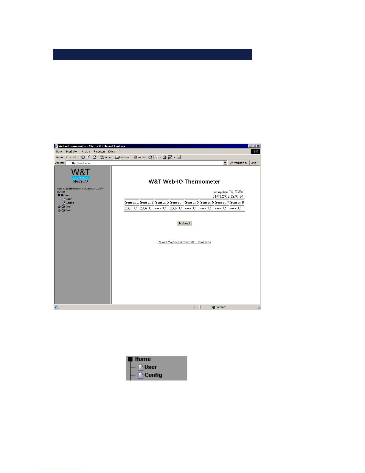
3 Configuring the Web-IO 8x Thermometer
Once all the hardware settings are made, you can go to the Web
configuration of the Web-IO 8x Thermometer. Start a Web browser and in the address line enter the IP address of the device:
http://172.0.0.10/
The Web-IO 8x Thermometer starts with the following display:
After clicking on „Login“ in the menu, you are asked to
enter a password.
The unit is shipped with no password assigned. Simply
click on the „Login“ button in the right frame and confirm
with the „OK“ button to start the configuration.
 Loading...