

Page 1

W&T
Manual
Web-IO 1x Thermometer
Web-IO 2x Thermometer
Web-IO 8x Thermometer
Type 10/100BaseT, 12-24V
Model 57601, 57603, 57604
Release 1.13, Nov. 2003
US 1.13 11/2003 ML
Page 2

W&T
2
© 10/2002 by Wiesemann & Theis GmbH
© 11/2003 by Wiesemann & Theis GmbH
Subject to errors and modifications:
Since we can make mistakes, do our statements should not be
applied without verification. Please bring any errors or misunderstandings to our attention, so that we can recognize and
correct them as soon as possible.
Perform work on and with W&T products only as described here
and after you have fully read and understood the manual. Unauthorized actions may result in hazardous conditions. We are
not liable for unauthorized use. If in doubt, please check with
us or your dealer!
Page 3
W&T
Subject to errors and modifications
3
Introduction
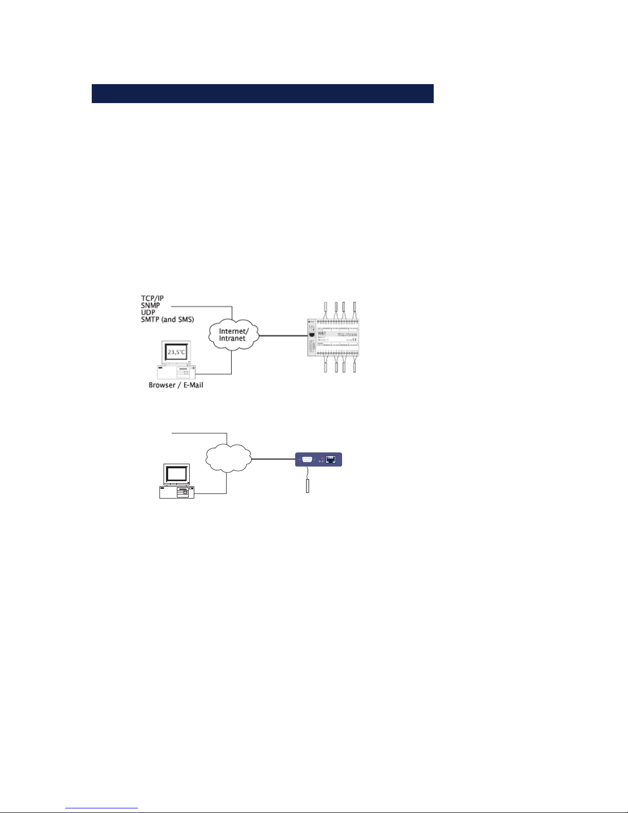
The Web-IO thermometer allows you to remotely monitor
temperatures and temperature trends via Internet browser or e-Mail. You can create your own HTML pages for visualizing the temperatures and generate personal information in order to be kept informed of current temperatures.
This manual contains all the information you will need to
install, configure and operate the Web-IO Thermometer.
Internet/
Intranet
23,5°C
Browser / E-Mail
TCP/IP
SNMP
UDP
SMTP (auch SMS)
Serial Port
Power
Network
Status
Error
Page 4

W&T
4
Contents
Introduction ............................................................................................ 3
1 Connections and Displays ............................................................. 6
1.1 Ethernet connection ........................................................ 6
1.2 Connecting the probe to the
Web-IO 1x Thermometer .................................................. 7
1.3 Connecting the probes to the
Web-IO 2x/8 Thermometer ............................................... 8
1.4 Supply voltage for the Web-IO 1x Thermometer ............... 10
1.5 Supply voltage for the Web-IO 2x/8x Thermometer ......... 10
1.6 LED displays ................................................................. 10
2 TCP/IP Configuration....................................................................13
2.1 Assigning the IP address ... ............................................ 13
2.1.1 ... using WuTility ................................................... 13
2.1.2 ... using DHCP-/BOOTP protocol ............................. 14
2.1.3 ... using ARP command .......................................... 16
2.1.4 ... over the serial interface ...................................... 17
2.1.5 ... using an RARP server (UNIX only) ........................ 18
2.2 Setting the subnet mask and gateway ............................. 19
2.3 Connecting the Web-IO 8x Thermometer ........................ 20
3 Configuring the Web-IO 8x Thermometer .............................21
3.1 Administration .............................................................. 22
3.1.1 LogOut ................................................................ 23
3.1.2 New Password ....................................................... 24
3.2 Configuration ............................................................... 25
3.2.1 Network ................................................................ 26
3.2.2 Text ..................................................................... 26
3.2.3 Time/Date ............................................................ 26
3.2.4 Time Zone ............................................................ 26
3.2.5 Time Server ........................................................... 27
3.2.6 Device Clock ......................................................... 28
3.2.7 Mail ...................................................................... 29
3.2.8 Alarm 1..8 ............................................................. 30
Page 5

W&T
Subject to errors and modifications
5
3.2.9 Data Logger ......................................................... 33
3.2.10 Memory .............................................................. 33
3.2.11 Protocol ............................................................. 33
3.2.12 Enable ................................................................ 34
3.2.13 Startup ............................................................... 35
3.2.14 Ports .................................................................. 36
3.2.15 Manufacturer ...................................................... 36
3.2.16 Up-/Download .................................................... 36
3.2.17 Diag ................................................................... 38
4 Single temperature polling... .....................................................39
4.1 ... via TCP/IP ..................................................................39
4.2 ... via UDP ..................................................................... 40
4.3 ... via SNMP ................................................................... 40
5 Incorporating the temperature into your own Web Site .... 41
6 Data Logger .......................................................................................43
7 Appendix ............................................................................................ 44
7.1 Calibration ................................................................... 44
7.2 Firmware Update ........................................................... 45
7.2.1 Where can I get the latest firmware? ........................ 45
7.2.2 Firmware update over the network under Windows ... 45
7.3 Emergency access ......................................................... 47
7.4 Extending the NTC cable ............................................... 47
7.5 Example of an XML configuration ................................... 49
7.6 Example for setting the „user.htm“ ................................. 63
7.7 Technical specifications ................................................ 70
Page 6

W&T
6
1.1 Ethernet connection
The network connection is provided in the form of an IEEE-8023-compatible terminal on a shielded RSJ45 plug located on the
front of the unit. Here the Web-IO 8x Thermometer can be connected to a hub or switch. The pin configuration corresponds
to a standard MDI interface (AT&T258), so that a 1:1 cable with
a length of maximum 100 meters can be used.
10BaseT, 10MBit/s or autosensing 100BaseT, 100/10MBit/s are
supported:
Please note that all plugs must be connected and disconnected only with the terminal devices are turned off.
!
Be sure that the network cable for the Web-IO does not
exceed a maximum permissible length of 100m.
1 Connections and Displays
1 = Tx+
2 = Tx-
3 = Rx+
4 = nc 5 = nc
6 = Rx-
7 = nc
8 = nc
RJ45 female (AT&T256 standard)
Page 7
W&T
Subject to errors and modifications
7
The Error LED on the front panel indicates the current link status: If it flashes at 1-2 second intervals, there is no connection
to the hub or the connection is faulty.
1.2 Connecting the probe to the Web-IO
1x Thermometer
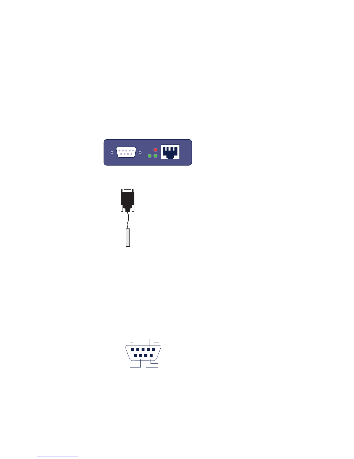
Connecting the NTC probe
U
The supplied NTC probe is already preconfigured and is simply
plugged into the DB9 connector in the device.
Connecting a PT100 probe
If you want to connect a PT100 probe, the pin configuration is
as follows:
Serial Port
Power
Network
Status
Error
RS232
1 = NTC 5 = PT100(weiß)
4 = NTC
8 = PT100(rot)
9 = PT100(rot)
7 = PT100
(weiß)
Page 8
W&T
8
1.3 Connecting the probes to the Web-IO 2x/8
Thermometer
Connecting the NTC temperature sensors
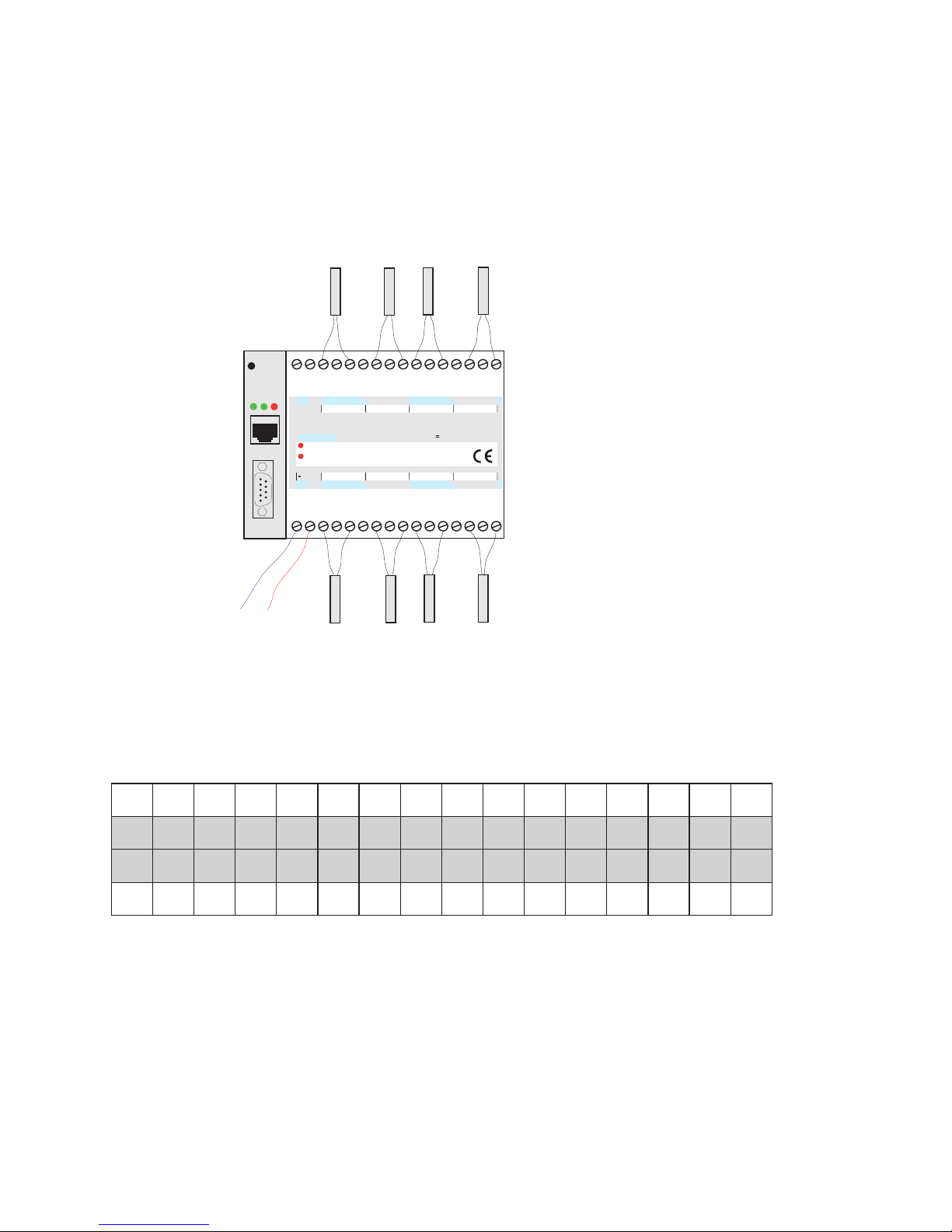
The eight NTC temperature sensors are connected to the unit
as shown in the following table. The numbering corresponds
to the screw terminals on the unit:
For information on extending the NTC cable, see Appendix
(7.4).
5CTN5CTN6CTN6CTN7CTN7CTN8CTN8CTN
71 81 91 02 12 22 32 42 52 62 72 82 92 03 13 23
1 2 3 4 5 6 7 8 9 01 11 21 31 41 51 61
1CTN1CTN2CTN2CTN3CTN3CTN4CTN4CTN
n.c.
1 2 1.RV 1.R+ 1.R- RG 2.R- 2.R+ 2.RV 3.RV 3.R+ 3.R- RG 4.R- 4.R+ 4.RV
5.RV 5.R+ 5.R- RG 6.R- 6.R+ 6.RV 7.RV 7.R+ 7.R- RG 8.R- 8.R+ 8.RVn.c.
http:// . . . /diag
on
error
Web-IO
8xThermometer
10/100BT, 12-24V, #57604
W&T
www.wut.de
12-24V
1
23
4
5678
9
10 11 12 13
14 15
16
17 18 19
20 21 22 23 24 25 26 28 29 30
31
32
27
Reset
Power
Status
Error
Serial Port
12-24V AC/DC
NTC1
NTC2
NTC3
NTC4
NTC5
NTC6
NTC7
NTC8
system error
Page 9
W&T
Subject to errors and modifications
9
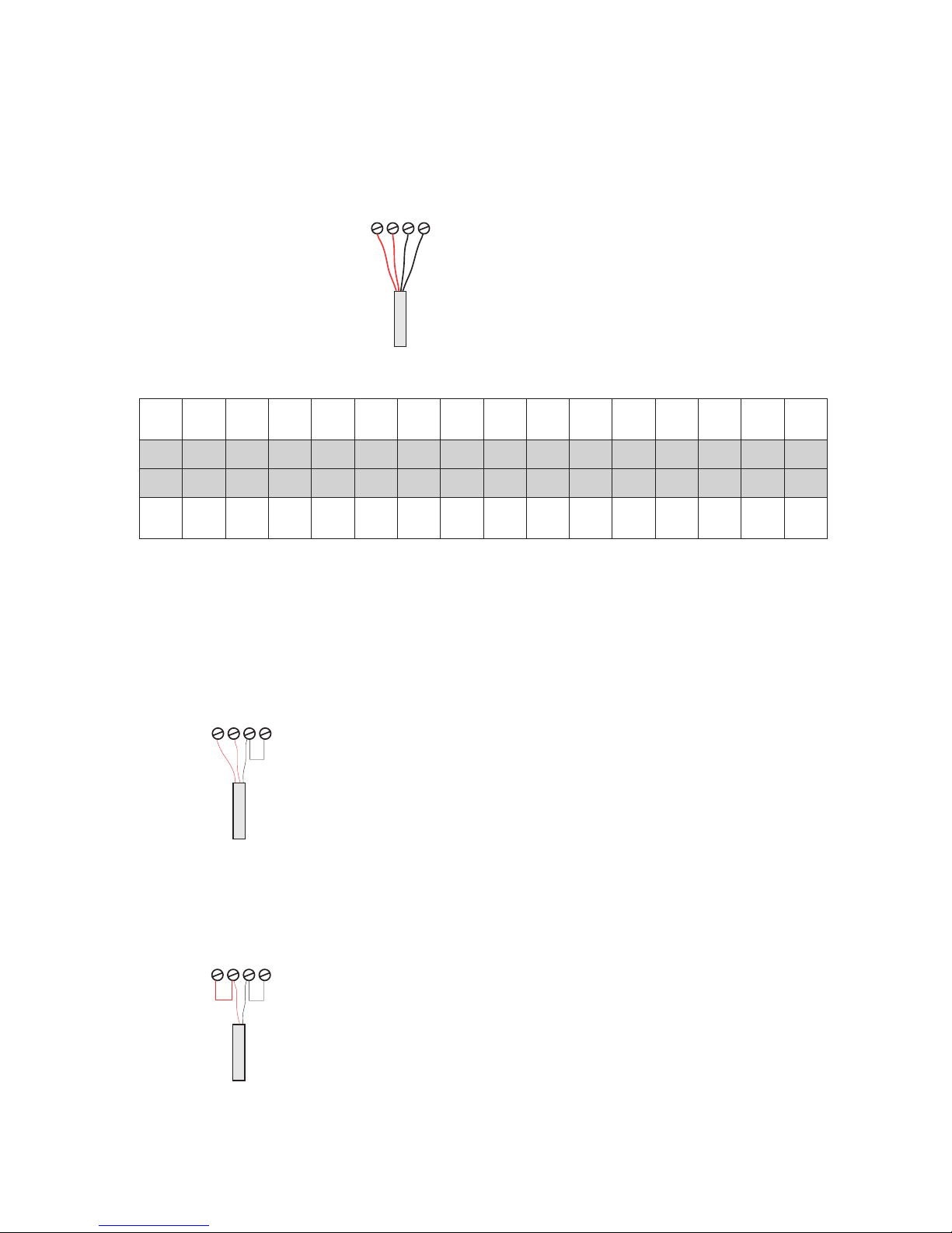
Connecting the PT100 temperature sensors
The cable for the PT100 4-wire temperature sensor may be routed over any desired length.
Connecting a PT100 3-wire sensor:
001TP
5
der
001TP
5
der
001TP
5
etihw
001TP
6.u5
etihw
001TP
6
etihw
001TP
6
der
001TP
6
der
001TP
7
der
001TP
7
der
001TP
7
etihw
001TP
8.u7
etihw
001TP
8
etihw
001TP
8
der
001TP
8
der
71 81 91 02 12 22 32 42 52 62 72 82 92 03 13 23
1 2 3 4 5 6 7 8 9 01 11 21 31 41 51 61
001TP
1
der
001TP
1
der
001TP
1
etihw
001TP
2.u1
etihw
001TP
2
etihw
001TP
2
der
001TP
2
der
001TP
3
der
001TP
3
der
001TP
3
etihw
001TP
4.u3
etihw
001TP
4
etihw
001TP
4
der
001TP
4
der
The corresponding wires of the PT100 3wire sensor have to be connected to the
screw terminals R+ and RV. Connect the
seperate wire to the screw terminal R- and
attach a bridge to GND.
Connect one wire of the PT100 2-wire sensor to the screw terminal R+ and the other
wire to the screw terminal R-. Add a bridge
from R- to GND and one from R+ to RV.
Connecting a PT100 2-wire sensor:
3
4
56
PT100
red red white white
3
4
56
PT100 2-wire
3
4
56
PT100 3-wire
Page 10
W&T
10
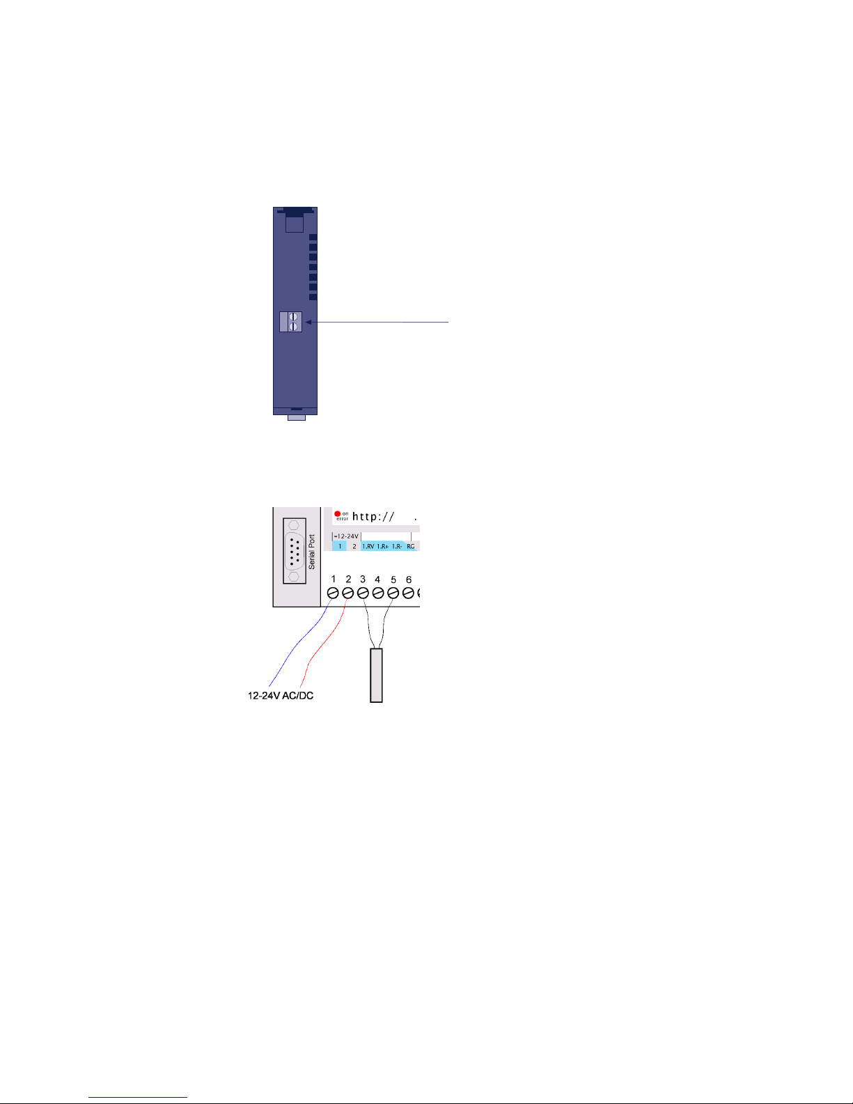
1.4 Supply voltage for the Web-IO 1x Thermometer
1.5 Supply voltage for the Web-IO 2x/8x Thermometer
The 12-24V AC/DC supply voltage is brought to the unit on
pins 1 and 2 located on the lower screw terminal block.
1.6 LED displays
■ Power-LED: Indicates the presence of supply voltage. If the
LED is not on, please check whether the power supply is
properly connected.
■ Status-LED: Flashes whenever there is network activity with
the Web Thermometer. Periodic blinking indicates that the
port has a connnection to another station.
Bottom 57601
supply
voltage
12-24V =/~
screw terminal
Page 11

W&T
Subject to errors and modifications
11
■ Error-LED: The Error-LED uses various blink codes to indi-
cate fault conditions on the device or the serial port.
Error-LED blinks 1x = Check network connection.
The Web-IO 8x Thermometer is not receiving a link pulse
from a hub or switch. Check the cable or the hub/switch port.
Error-LED blinks 2x or 3x
Perform a reset by disconnecting the supply voltage or pres
sing the reset button. If the error is not cleared,
reset the unit to the factory defaults. Since this resets all net
work settings, you should first write them down.
Config -> Session Control -> LogOut ->
Restore Defaults
After a reset the device is restored to its factory default set-
tings. Make your network settings again as necessary. For
more information on menu guided configuration, see section 3. and following.
Power-LED + Status-LED + Error LED on = selftest failure
The self-test, which is performed after each start or reset of the
Web-IO 8x Thermometer, could not be correcly finished due to
an incomplete firmware update. The device is no longer operational in this state. Please return the unit.
Page 12

W&T
12
Supplementary LED (for internal Web-IO 1x Thermometer)
■ on error http://xxx.xxx.xxx.xxx/diag -LED: Indicates in-
ternal configuration errors. For error diagnostics, open page
http://xxx.xxx.xxx.xxx/diag in the unit.
■ system error: Critical hardware error. Try to restart the unit
by interrupting supply voltage. If the condition persists, please return the unit for evaluation.
!
If the Web-IO Thermometer has no IP-address or the
address 0.0.0.0 the LEDs on error and system error stay
on after a reset or restart! The Web-IO 1x Thermometer
starts blinking for three times after a short time. After assigning a IP-address the LEDs will go off.
Page 13

W&T
Subject to errors and modifications
13
2 TCP/IP Configuration
Once the hardware has been configured as described above,
the IP address necessary for operating in a TCP/IP network
must be assigned. Please request the correct value for this parameter from your system administrator.
!
The IP address must be unique throughout the network.
2.1 Assigning the IP address ...
There are five ways to first assign the IP address for the Web-IO
8x Thermometer:
2.1.1 ... using WuTility
First download the „WuTility“ tool from the WuT Homepage:
(http://www.wut.de)
Be sure that the PC you are using to assign the IP address is in
the same subnetwork as the device and that both the PC and
the device are connected to the network.
- Start „WuTility“ and click on the scan icon:
- Select your Web-IO Thermometer from the displayed list using
the MAC address:
Page 14

W&T
14
2.1.2 ... using DHCP-/BOOTP protocol
Many networks use DHCP (Dynamic Host Configuration Protocol) or BOOTP for centralized and dynamic assignment of the
IP addresses. Which of the two protocols are used makes not
difference to the Web-IO devices, since DHCP is simply a downward compatible extension of BOOTP. DHCP servers thus also
use the requirements of BOOTP clients.
The MAC address is found on the label affixed to the housing:
- Click on the „Assign IP Address“ symbol:
- In the resulting window,k enter the desired IP address for the
device and confirm with „OK“: :
The device acknowledges the entry with an audible tone (2x/
8x Thermometer only) and accepts the set IP address. After
clicking again on the Scan button, this address is displayed in
the WuTility.
5xxxx [Typ]
EN=00c03d004a05
OK xxxxxx
Ethernet-address
Page 15

W&T
Subject to errors and modifications
15
The following parameters can be assigned to the Web-IO 8x
Thermometer using these protocols:
■ IP address
■ Subnet mask
■ Gateway address
It is not possible to assign other parameters or a lease time.
Functionality
To obtain an IP address, the device sends after every new start
a corresponding BOOTP request as a broadcast to the network.
The resulting reply generated by the DHCP/BOOTP server contains in addition to the IP address the subnet mask and gateway address. The Web-IO 8x Thermometer immediately places
this information in its non-volatile memory.
When placing the unit into service in DHCP/BOOTP networks,
please consult with your system administrator. If DHCP will be
used for assigning the address, you must mention that a reserved IP address is required. To maintain the respective address
database, the administrator needs the Ethernet address of the
Web-IO 8x Thermometer, which can be found on the sticker on
the housing.
Once the necessary entries have been made, the device automatically obtains the desired IP address after each reset. To ensure that the Web-IO 8x Thermometer can also be reached if
the DHCP/BOOTP server fails, the previous IP address is retained if no reply follows.
Page 16

W&T
16
!
In DHCP environments the IP address to be assigned
must be reserved by means of a fixed link to the
Ethernet address of the Web-IO 8x Thermometer.
Under Windows NT this is done in the DHCP Manager
under menu item „Reservations“. Linux provides the file
„dhcpd.conf.“ for this purpose, in which a corresponding
entry must be made.
2.1.3 ... using ARP command
The requirement is a PC which is located in the same network segment as the Web-IO 8x Thermometer and which
has TCP/IP protocol installed. Read the MAC address of
the device on the device (e.g.. EN=00C03D0012FF). Under
Windows you first ping another network station and then
insert the command line shown below into the ARP table
as a static entry:
arp -s <IP-address> <MAC-address>
e.g. under Windows:
arp -s 172.0.0.10 00-C0-3D-00-12-FF
e.g. under SCO UNIX:
arp -s 172.0.0.10 00:C0:3D:00:12:FF
Next ping the device again (in our example ping
172.0.0.10). The address is now stored in non-volatile memory.
!
This method can only be used if no IP address has yet
been assigned to the Web-IO 8x Thermometer, i.e. the
entry is 0.0.0.0. To change an already existing IP
address, you must open the configuration menu through telnet
or select the serial path (2.1.4).
Page 17

W&T
Subject to errors and modifications
17
2.1.4 ... over the serial interface
In contrast to the procedure described above, you can change
an already existing IP address for the Web-IO 8x Thermometer
over the serial interface.
Connect the RS232 port on the unit to a PC and start a terminal
program (e.g. Hyperterminal). Establish a direct connection
through your COM port and set the serial properties 9600 baud,
no parity, 8 bits, 1 stop bit, no protocol. Perform a reset by interrupting the supply voltage on the unit. When the green Status LED comes on, enter (on the terminal) the letter „x“ at least
three times until the message „IPno.+<Enter>“ appears. Now
enter the IP address in the usual decimal format
(xxx.xxx.xxx.xxx) and confirm your entry with <Enter>.
!
Backspacing will not correct an error in entering text.
The procedure must be repeated.
If the entry was correct, the assigned IP address is acknowledged, otherwise the monitor shows the current IP address along
with the message „FAIL“. This procedure may be repeated as
often as desired.
If you want to shut down the BOOTP (DHCP) functionality in
this status directly, type a „-0“ behind the IP-address
(192.168.5.12-0).
You will need a null modem cable for connecting to a terminal:
xxx -> Web-IO Thermometer
IP no.+<ENTER>: <- Web-IO Thermometer
172.17.231.99-0 -> Web-IO Thermometer
172.17.231.99 <- Web-IO Thermometer
Page 18

W&T
18
2.1.5 ... using an RARP server (UNIX only)
Working with an RARP server activated under UNIX is based on entries in the configuration files /etc/ethers and
/etc/hosts. First add a line to /etc/ethers with the allocation of
the Ethernet address of the Web-IO 8x Thermometer to the
desired IP address. In /etc/hosts the link with an alias name is
then created. Once you have connected the device in the network segment of the RARP server, you can assign the desired IP
address over the network.
Example:
Your Web-IO 8x Thermometer has MAC address
EN=00C03D0012FF (sticker on the unit). You want it to
have IP address 172.0.0.10 and the alias name WT_1.
Entry in file /etc/hosts: 172.0.0.10 WT_1
Entry in file /etc/ethers: 00:C0:3D:00:12:FF WT_1
If the RARP deamon is still not activated, you must start it
using the command „rarpd -a“.
A crossed serial cable is needed to connect the device to a terminal:
Com-Server <> PC, 9-pin
W&T Art. No. 1199x
1
2
3
4
5
6
7
8
4
3
2
1
5
6
8
7
DB9 socket
DB9 socket
Page 19

W&T
Subject to errors and modifications
19
!
To make the subnet mask and gateway settings, the con
figuration PC must be located in the same IP sub-network
as the Web-IO Thermometer. Otherwise no communicati-
on with the device will be possible.
Once you have assigned the IP address, set the subnet mask
and gateway as follows:
1. Open a Web browser and enter the IP address of the device
in the address line.
2. Select Config. in the configuration menu
3. Since no password has yet been assigned, leave this line
blank and confirm by clicking on the Login button and then
„OK“.
4. Select the following path in the menu:
Config -> Device -> Network
5. Now enter the subnet mask and gateway and confirm using
the Send button.
2.2 Setting the subnet mask and gateway
When working in routed environments, the Web-IO Thermometer must also be told which subnet mask is valid for the respective network segment and which router is being employed. You
can obtain the valid values for both parameters from your system administrator.
The subnet mask and gateway can be set after assigning the IP
address using the Web-Based Management tool (3.2.1).
Page 20

W&T
20
6. Select the following path in the menu:
Config -> Session Control -> LogOut
and click on the Save button.
The device has now saved your settings.
2.3 Connecting the Web-IO 8x Thermometer
In an Intranet
Once all the settings have been made, the Web-IO 8x Thermometer can be accessed through any desired Web browser. Enter
as an address the IP address or (if you have specified a corresponding DNS entry) the host name for the device. The device
will then send its information back to the browser.
In the Internet
To make the Web-IO 8x Thermometer accessible from the Internet, you will need a free, external and static IP address which
your router can reach from the Internet. Ask your ISP to provide
you with a DNS entry so that the Web Thermometer can be accessed by means of a URL. Then you need only to divert HTTP
port 80 in your router to the IP address of the Web-IO 8x Thermometer. This is done by means of an entry in the NAT table,
such as:
http 172.0.0.10
Page 21
W&T
Subject to errors and modifications
21
3 Configuring the Web-IO 8x Thermometer
Once all the hardware settings are made, you can go to the Web
configuration of the Web-IO 8x Thermometer. Start a Web browser and in the address line enter the IP address of the device:
http://172.0.0.10/
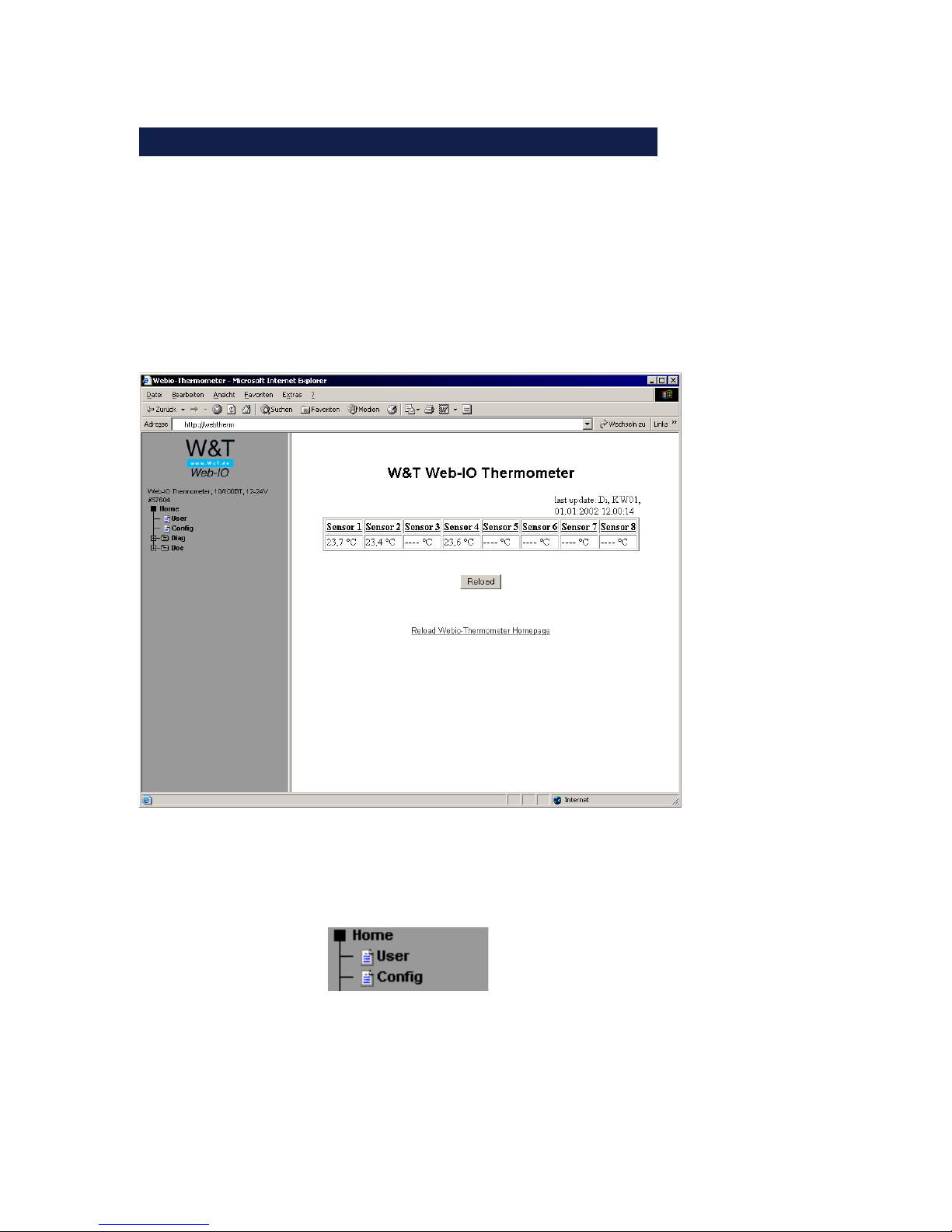
The Web-IO 8x Thermometer starts with the following display:
After clicking on „Login“ in the menu, you are asked to
enter a password.
The unit is shipped with no password assigned. Simply
click on the „Login“ button in the right frame and confirm
with the „OK“ button to start the configuration.
Page 22
W&T
22
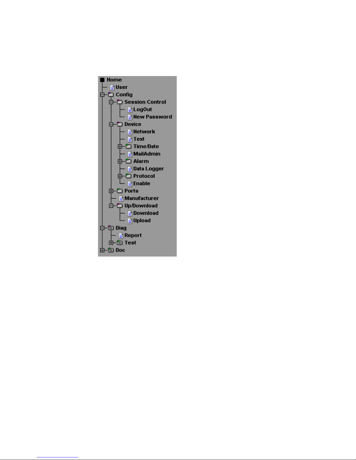
You are shown the following menu tree for configuring the device:
3.1 Administration
To administrate the Web-IO Thermometer, select „Session Control“ in the menu.
Page 23

W&T
Subject to errors and modifications
23
3.1.1 LogOut
Here you will find the following functions:
Save saves all the settings and changes you have made. (Must
also be done after clicking the „Send“ button.)
Flush cancels all the settings you have made during this session. No changes are saved.
Restore Defaults resets the Web-IO 8x Thermometer.
See also XML-Up-/Download (3.2.16).
!
Any user pages that may be stored are also lost.
Firmware Update opens the update port. Now you can run an
update of the module firmware.
Page 24

W&T
24
3.1.2 New Password
You can assign two different passwords to the device in
order to protect certain areas of the configuration. A distinction is made between the following users:
■ Admin (all configuration rights)
■ Config (e.g. house technician: no network internals)
i
Only one user can be in the configuration mode. If there
is already a user in configuration mode, only the Admin
user has authorization to start a new configuration
session. The previous session is then quit without saving.
If you do not assign a password for one or both users, all
functions are available to these users. If for example you
assign a password for the Config user but none for the
Admin, the Admin parameters will also be displayed when
logging in to Config, as long as these parameters are not
password protected.
Passwords may have a maximum of 30 characters.
Page 25
W&T
Subject to errors and modifications
25
!
If no password is entered in the line and the
„Send“ button is activated, the current password
will be deleted after saving.
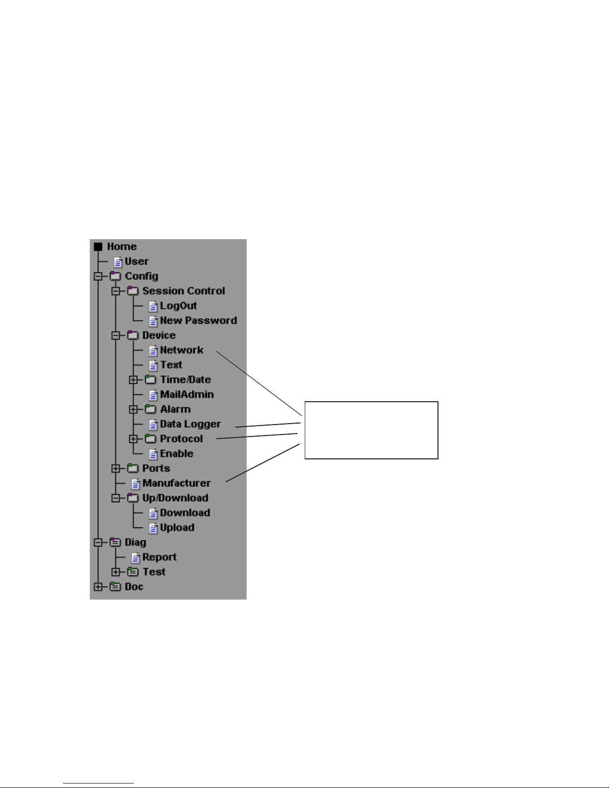
3.2 Configuration
only with
administrator rights
Page 26

W&T
26
3.2.1 Network
Once you have assigned the IP address and are able to access
the unit from your browser, you can now make the network settings after the fact. If you want to use host names instead of IP
addresses in the mail configuration (3.2.7) or in the time server
function (3.2.5), you can spcecify two DNS servers here which
can resolve these host names.
i
The BOOTP-Client (DHCP) can be turned off if there is
any problem with the IP-address assignement.
3.2.2 Text
Enter here a name and descriptive text that you want to appear
on the start page.
3.2.3 Time/Date
Set the current time of day and date. These settings are applied
immediately and do not need to be saved.
!
After a device reset these settings are also reset.
3.2.4 Time Zone
Next configure the time zone. This is preset to Central European Time (CET) with an offset of +1 hour from GMT.
Likewise you can make settings for switching back and
forth between daylight savings and standard time. Here
again enter the offset to GMT and enter the start and stop
time for daylight savings time.
Page 27

W&T
Subject to errors and modifications
27
Example for the start time:
Month: March
Mode: last
Weekday: Sunday
Time: 02:00
This means that summer time begins on the last Sunday in
March at 02:00 in the morning.
Configure the stop time in just the same way.
!
Be sure that in the Device Properties (Config -> Device ->
Enable) the checkboxes „Apply Timezone“ and „Apply
Summertime“ are activated if you wish to use these
functions.
i
The rule for specifying summer time: Start: On last Sun
day in March at 02:00 hours. End: On last Sunday in October at 03:00 hours.
3.2.5 Time Server
The Web-IO Thermometer supports access to time servers. These make it possible to obtain the time of day over the Internet
or Intranet. This time can be used directly by the Web-IO Thermometer.
Enter here the IP address or host name of the time server(s). If
you want to use a host name for a time server, please enter one
or two DNS servers (IP address) so that this host name can be
resolved. Alternately, the IP address of one or two time servers
can be entered. In this case you do not need an entry for the
DNS server.
Page 28

W&T
28
The time sent by the time server is always GMT, which means
that you still have to make the settings for your time zone and
daylight savings time in order to ensure a correct time display.
!
Access to the time server takes place after saving the
settings, after turning on or resetting the device, and at
the configured full hour. Be sure that the checkbox
„Apply TimeServer“ is activated under Device Properties
(Config->Device->Enable).
Successful synchronization is indicated by the display with a
„*“ behind the time of day on the home or user page.
A listing of public time servers can be found at:
http://www.eecis.udel.edu/~mills/ntp/servers.html
3.2.6 Device Clock
Here you set the time of day if the device is not using the
time server functionality. These settings are lost as soon
as the device is disconnected from power.
Page 29

W&T
Subject to errors and modifications
29
3.2.7 Mail
Here you configure the e-Mail function of the Web-IO Thermometer. The e-Mail function allows you to forward an information or alarm mail to one or more e-Mail or SMS recipients.
Enter the name you want to appear at the e-Mail recipient. Now
the reply address is set which the Web-IO Thermometer uses to
identify itself.
!
Some mail servers require a login by the e-Mail user
in order to identify him. It may be necessary to
enter an existing mailbox so that an SMTP access is
accepted. If there are problems in accessing the mail
server, you may have to create a new mailbox for the
Web-IO Thermometer.
In the next step, set the IP address of your mail server or its
host name which the device should refer to. If the e-Mail port
does not correspond to the standard port 25, you can append
a colon to the address:
mail.provider.com:476
Be sure that „Mail enable“ is set under Device Properties
(Config -> Device -> Enable).
Page 30
W&T
30
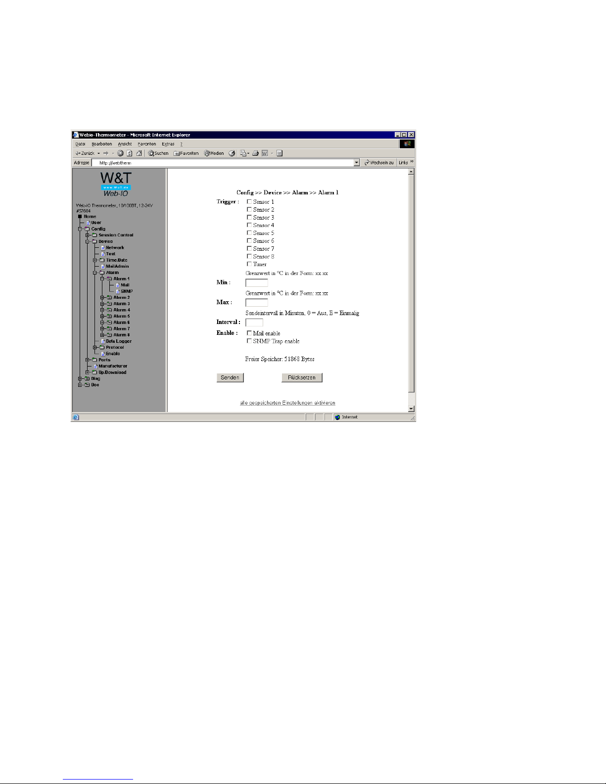
3.2.8 Alarm 1..8
Eight equal alarms are available with two operating modes:
1. Timer mode:
Select the timer under Trigger. Limits do not need to be specified at this point. Set the desired send interval and select „Mail
enable“ and/or „SNMP Trap enable“.
Page 31

W&T
Subject to errors and modifications
31
2. Limit mode:
Select one or more sensors as triggers and after Min and/or Max
enter the limits which when exceeded should trigger an alarm.
Enter the send interval at which the alarm e-Mail should be sent.
For no alarm, enter a send interval of 0. Entering an E means
that an alarm is triggered whenever the limit is exceeded (high
or low). The temperature measurement is made each full minute. If a limit is violated for the first time, the alarm is triggered
directly. As long as the temperature is still not within the valid
range, successive alarms are issued at the specified intervals.
!
You can also mix the operating modes. Note however
that an alarm is triggered asynchronous to the interval
and the interval for the alarm time is restarted.
Now specify whether the alarm is to be sent as an e-Mail or
SNMP trap.
Mail
The „Mail-Text“ is variable. To include temperatures in the text,
use the expression „<Tx>“, where x is the number of the temperature sensor. All the sensors can be displayed regardless of
the „Trigger“ settings. To display the time and date information, use the expression „<Z>“.
Specify the e-Mail address of the recipient. To configure multiple recipients, separate their e-Mail addresses with semicolons.
Specify an entry for the „Subject“ field.
Page 32

W&T
32
With the option „Attach thermo.csv enable“ you have the possibility of adding complete contents of the data logger in semicolon-separated CSV format as Mail appendix. The time base of
the output corresponds to the pre-setting of the data logger.
!
The file is produced dynamically in the device, so that
with large logging the compilation of the CSV file can
take up up to 30 seconds. In this time no other Mail transmissions can take place. Queued alarms are implemented immediately after mailing the Mail with appendix.
SNMP
Enter here the IP address of the station with the SNMP Manager
software to which the SNMP information should be sent.
Just as in the case of the mail function, you can also enter here
a „Trap Text“ which is sent to the Manager software. This has
the same entry format as the mail text.
i
If you have entered an administrator password, you
must enter this in your Manager software as the
„community string“!
TCP
The alarm message is sent over a TCP/IP Socket to a TCP/IP server. Indicate the IP address of the server and the port number.
Here the same expressions apply as with the Mail text.
Page 33

W&T
Subject to errors and modifications
33
3.2.9 Data Logger
Under „Timebase“ enter the desired memory frequency and under „Select Sensor“ select the sensors whose measurements you
want to store. Both settings have an effect on the memory
depth of the unit. For example, after activating all eight sensors with a time base of 15 min. you will have a memory depth
of 85 days and 7 hours. The measured values will stay in a
fixed ring-buffer in the device and will be available even after a
reset or a power-off. Read more about the data logger on page
43.
3.2.10 Memory
After choosing this menu item and after a click on the „Erase
memory“ button all measured values which have been saved in
the device will be erased.
3.2.11 Protocol
This function is used to save the individual data on separate
servers or directly to your own applications without using the
Web interface.
Enter here a UDP port the device uses for listening and answering. The default setting is port ‚42279‘.
Page 34

W&T
34
3.2.12 Enable
Here the global functions of the device are activated and deactivated:
Update Enable for the update port can be turned on or off. If it
is activated, it is possible to load the firmware update into the
device. Regardless of this setting the Web-IO 8x Thermometer
can be opened for an update under „LogOut -> Firmware Update“.
Mail Enable Activates or deactivates the e-Mail function
SNMP Enable Activates or deactivates the SNMP function
UDP Enable Activates access to the temperature via UDP.
GET Single Header Enable A GET /Single request means that
the device sends the configured name and IP address of the
device in addition.
Apply Time zone Local time is used. This means that the device calculates the entered offset to GMT. If this function is
disabled, no offset is used.
Apply Summer time Activates summer time (daylight saving
time). This function works only in conjunction with Apply Time
zone.
Apply Time Server Activates the use of a time server for set-
ting the time of day. Enter at least one time server so that this
function will work.
Startup selects the page which will be displayed as default
when using the web browser.
Page 35

W&T
Subject to errors and modifications
35
3.2.13 Startup
Here you can chose which web-page will be loaded when there
is no further page information typed after the address. The
standard page is „index.htm“, as it is the internet.
Sometimes some applications need to load different pages on
startup e.g. to hide the configuration menu. It is also possible
to load the pages by typing the address directly for „user.htm“
or „log.htm“.
The pages will not be lost at this choice and they are loadable
with the explicit address on every time.
The changes will be made after saving the configuration.
i
After a factory default reset the startup-page will be
„index.htm“ again.
Page 36
W&T
36
3.2.14 Ports
If desired, you can assign a name and descriptive text for the
individual sensors which you want to have displayed on the
Web pages.
3.2.15 Manufacturer
This contains information about the manufacturer and the
company providing the support. Change this information
only if you can and want to assume support responsibility.
In addition, you can change the logo in the menu frame
here. Simply enter the path to your logo file in this text
field. This may be a local or external path.
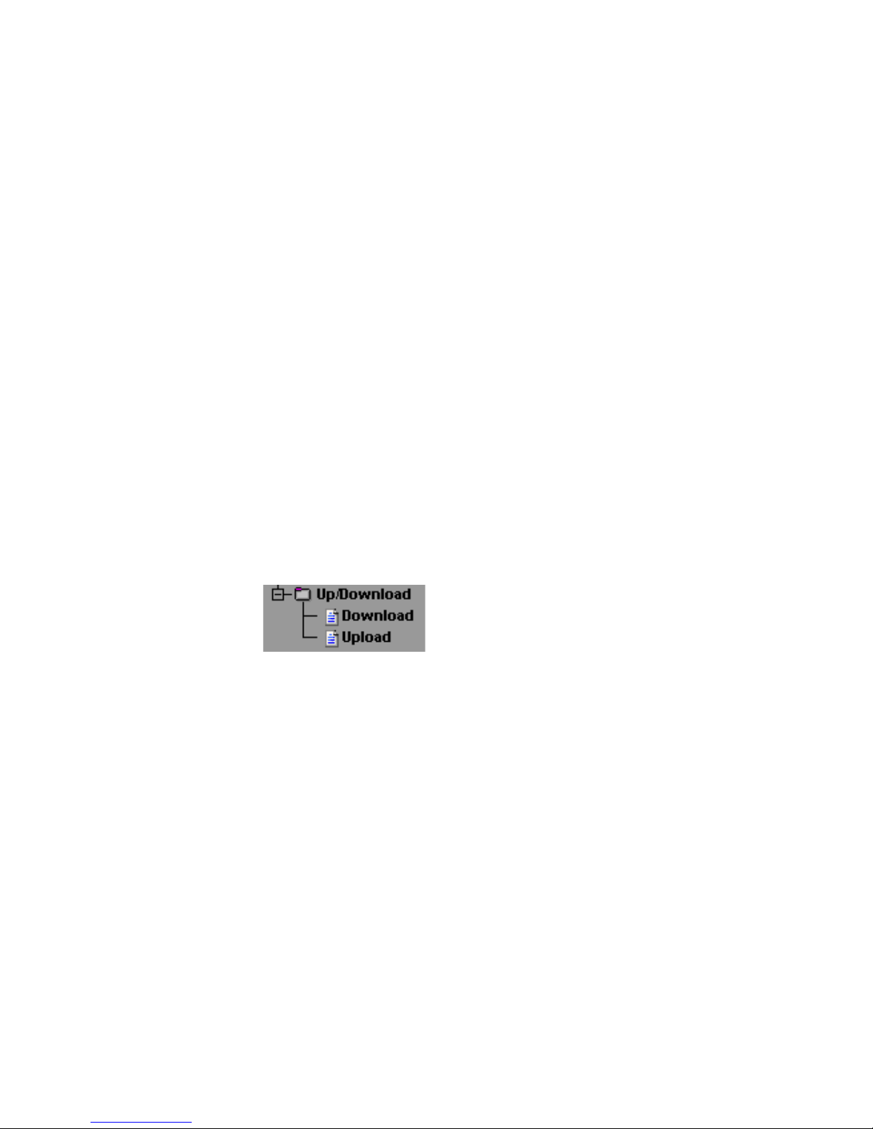
3.2.16 Up-/Download
In the download area you can download the XML configuration as well as the three user pages (home.htm,
user.htm, log.htm) for further editing.
Here you can load the settings for the Web-IO Thermometer
into the device using XML Upload. To read out the current configuration, click on XML Download.
With some Web browsers the correct code can be output using
„Display View -> (Frame-) source text“ only after clicking on the
XML Download button.
Page 37

W&T
Subject to errors and modifications
37
For the XML upload you create a text file with the corresponding parameters and load this file into the device. Your configuration must begin with the expression
<io-AN8.1>
and end with the expression
</io-AN8.1>
The sequence of the parameters to be set corresponds to
the order in which they appear in the configuration menu
starting with „Device“.
The syntax for configuring using XML is as follows:
<Option>
<Parameter1> VALUE </Parameter1>
<Parameter2> VALUE </Parameter2>
</Option>
The individual options and parameters correspond to the
configuration items in the browser menu.
!
Please note, especially for mass updates and configurations, that the IP address stored in the XML file is also al
ways sent and then needs to be matched.
An example can be found in the Appendix (6.4).
In addition, the user pages (user.htm, home.htm, log.htm)
can be exchanged in the Upload area.
An example can be found in the Appendix (6.5).
The menu item „Upload -> GIF“ can be used to replace the
logo displayed in the menu and then directly stored in the
unit.
Page 38

W&T
38
3.2.17 Diag
In this area the device displays all the gathered errors under Report. You can identify the error here with activity
on the on Error http LED.
Report
If the „on error http“ LED on the unit is flashing, this error is entered in a list on the Report page.
This page reports all errors which the device can output.
Deleting the report also resets the flashing LED on the
unit‘s front panel.
Clicking the OK button saves the report. The LED continues to flash.
Sensor Type
Indicates for each channel whether a PT100 or NTC sensor is connected. If one or more channels is used, an NTC
is indicated by default.
Test LED
The Test LED allows you to locate a device when more
than one is being used. When the LED test is started, the
LED‘s on the device will come on for two seconds.
Page 39

W&T
Subject to errors and modifications
39
4 Single temperature polling...
4.1 ... via TCP/IP
As a special function it is possible to use a socket connection
to manually poll the current temperature values in CSV format
(comma-separated data).
Send the following to port 80 on the device:
GET /Thermo.csv
To get the single current temperature value, send:
GET /Single1
where the number behind „Single“ is the number of the
sensor (Sensor 1 - Sensor 8)
GET /Single4
thus provides the temperature from Sensor 4.
To output all temperatures at once, send the expression:
GET /Single
(Equal whith “GET /Single1” for the Web-IO 1x Thermometer)
Page 40

W&T
40
4.2 ... via UDP
Open a UDP connection to the IP address of the unit or to
the Net ID as a broadcast and to port 42279 (default can
be changed).
Then send the device one of the expressions listed under
4.1 and the device will return the temperature on the port
you are using.
i
When using more than one device, it may be useful in
the case of broadcast sends to allow the name and
the device IP address to be output as well. To do this, activate „GET Single Header enable“ in the global settings (3.2.11).
4.3 ... via SNMP
The individual sensors can be directly polled using SNMP
Get instructions. You reach the sensors of the thermometer
through the following path:
<IP-address> 1.3.6.1.4.1.5040.1.2.1.1.1.0 = number of sensors
<IP-address> 1.3.6.1.4.1.5040.1.2.1.1.3.1.1.x = temperature va-
lue, where x is the sensor number.
<IP-address> 1.3.6.1.4.1.5040.1.2.1.1.4.1.1.x = temperature va-
lue three-digit integer number, whithout comma serperation,
where x is the sensor number.
The OID for the 2x thermometer is:
<IP-address> 1.3.6.1.4.1.5040.1.2.2....
The OID for the 1x thermometer is:
<IP-address> 1.3.6.1.4.1.5040.1.2.3....
Page 41

W&T
Subject to errors and modifications
41
An MIB for incorporating into Management applications can be
found and downloaded from the datasheet page at the WuT Homepage http://www.wut.de .
It is possible to integrate the temperature on your own Web site
using an implemented Java applet. An example for this applet
is already contained in the unit:
http://172.0.0.10/app.htm
To incorporate the applet for temperature monitoring into
the HTML page, you must insert the following HTML tag
at the point where the applet is inserted:
<APPLET ARCHIVE=“A.jar“ CODE=“A.class“ Codebase=“Http://
WebTherm
/“
Width=“
width
“ Height=“
height
“>
Now the following parameters can be optionally specified:
Specifying the background color:
<Param Name=“BGColor“ Value=“#
RGB-value
“>
Specifying the font color:
<Param Name=“FGColor“ Value=“#
RGB-value
“>
i
The RGB value is specified as a 24-bit Hex value.
e.g.:Value=“#2F3C09" Upper and lower case
are not critical.
Specifying text alignment:
<Param Name=“Align“ Value=“
const
“>
5 Incorporating the temperature into your own Web Site
i
If you have entered an administrator password, you
must enter this in your Manager software as the
„community string“!
Page 42

W&T
42
const must be one of the following constants:
■ Left
■ Center
■ Right
Upper and lower case are not critical.
If a parameter is omitted or incorrectly used, the following
standard values are applied:
Once all the parameters are entered, you must close the
HMTP tag with </Applet>
Example:
<Applet ARCHIVE=“A.jar“ CODE=“A.class“
Codebase=”http://127.0.0.1” Width=”300” Height=”100”>
<Param Name=”BGColor” Value=”#0000FF”>
<Param Name=”FGColor” Value=”#FF0000”>
<Param Name=”Align” Value=”Center”>
</Applet>
The font size is automatically calculated from the size of
the applet. The font is proportionally enlarged until it fits
into the applet in height and/or width.
The applet is updated every 60s
roloCGB)etihw(FFFFFF#
roloCGF)kcalb(000000#
ngilAthgiR
Page 43
W&T
Subject to errors and modifications
43
6 Data Logger
The measured values will stay in a fixed ring-buffer in the device and will be available even after a reset or a power-off.
i
The values of the data logger can be viewed via the
user-page in the device (home -> user or http://
xxx.xxx.xxx.xxx/user.htm).
The menu item config -> device -> data logger -> memory gives
you the possibility to erase the logger memory.
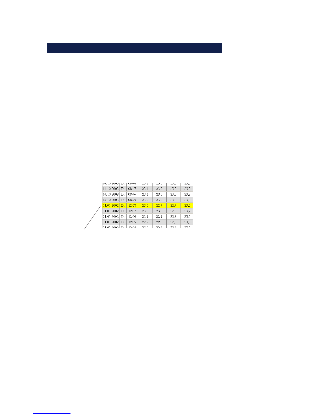
A interruption of the time line e.g. after a reset or a subsequent
time server synchronization will be displayed as a yellow line in
the log table.
i
if alarm limits are set all temperatures which are not in
the valid range will be displayed with red backround color.
time line interruption:
yellow marked line
Page 44
W&T
44
7 Appendix
7.1 Calibration
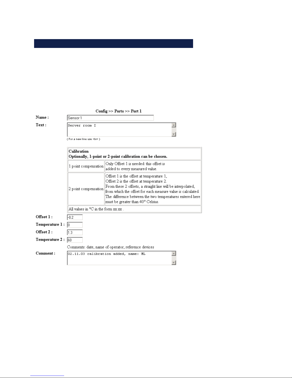
The single sensors can be calibrated with one-point or twopoint reference measurements and the input of offset values.
With the one-point-compensation the entered value is added to
the measured temperature level. The two-point-compensation
adds a straight line around the entire measuring range to adapt. In order to store calibration procedures, the performing
user can deposit a comment.
Page 45

W&T
Subject to errors and modifications
45
7.2 Firmware Update
The firmware for the Web-IO Thermometer is under constant
further development. The following section describes how to
upload the newest firmware.
. Where can I get the latest firmware?
. Firmware update over the network under Windows
7.2.1 Where can I get the latest firmware?
The latest firmware including the available update tools and a
revision list is published on our Web pages at: http://
www.wut.de
Before downloading, please write down the 5-digit model number located on a sticker on the Web-IO Thermometer. From for
Homepage you can now reach the product overview sorted by
article numbers, from which you can go directly to the data
sheet for the device. From here follow the link to the current
firmware version.
7.2.2 Firmware update over the network under Windows
Required is a PC under Windows 9x/NT/2000/XP having a network connection and activated TCP/IP stack. For the update
process you will need two files which are available for downloading at the Homepage http://www.wut.de .
Page 46

W&T
46
· The executable update tool for loading the firmware into
the Web-IO Thermometer.
· The file with the new firmware that is loaded into the Web-IO
Thermometer.
No special preparation of the Web-IO Thermometer is necessary in order to perform the firmware update.
The WuTility used for the update detects all the WuT devices in your network and is for the most part self-explanatory. If you still have questions or are unclear about
anything, please use the associated documentation or online help.
!
Never intentionally interrupt the update process by
disconnecting the supply voltage or pressing
the Reset button. Following an incomplete update
the Web-IO Thermometer will incapable of operating.
Never mix files of various version numbers in the file
name. This will result in inoperability of the device.
The Web-IO Thermometer automatically detects when
transmission of the new firmware is complete and then independently performs a reset.
Page 47

W&T
Subject to errors and modifications
47
7.3 Emergency access
The serial connection (DTE) on the unit provides an emergency access. This is enabled as follows:
Use a serial cable to connect the unit to a PC (null modem
connection) and start a serial terminal program. Configure the program for
9600,8,N,1,no handshake
Press the Reset button on the unit. As soon as the signal
tone is audible, press the following letters on your keyboard 3x for the individual accesses:
3x „u“ Opens the update port. A firmware update can
now be performed.
3x „f“ Resets the unit to its factory default settings. All
previous configurations and settings (including
the IP address) are lost.
3x „p“ Deletes all assigned passwords.
For confirmation the System Error and the on error http LED‘s
flash multiple times in succession.
3x „x“ (Enter directly after pressing the Reset button and
before the signal tone) Assigning/changing the
IP address. When prompted, enter the desired IP
address.
7.4 Extending the NTC cable
If necessary the NTC sensor cable can be extended. Recommended is a cable with as large a gauge as possible
(at least 0.75²mm or AWG 18) in order to ensure that the
cable impedance is not too great (below 10 ohms), which would
falsify the measured values.
Page 48

W&T
48
Using a copper cable with a cross-section of 0.75mm² and a
length of 100m, the cable impedance will be 4.6 ohms, which
is within the tolerance range.
For copper cables verify the impedance using the following formula:
The result of this calculation must lie below 10 ohms.
More critical than the cable length are the external noise
effects on the cable. This can result in inaccurate readings. Be sure therefore that the cable is isolated from
other installations and thus not subjected to electromagntic radiation. Twisted-pair cable (e.g. Cat.5) wil also help to
suppress noise.
!
The accuracy and noise immunity of the sensors
depend on the cable length and any noise
sources which may be present. This means that the
local conditions of some installations may, if not rectified,
result in measuring errors or inaccuracies. For a new
installation, we recommend using a 4-conductor cable in
order to allow for later use of PT100 technology.
We have taken a number of steps in order to ensure that
noise sources such as 50Hz interference from the AC cable does not have an effect on the measured values. You
can easily check to see how effective our noise suppression is working in your environment by using fixed resistors instead of NTC sensors. The measured values
should in this case fluctuate by a maximum of 1 decimal
point.
2 length [m]
58 cross section [mm²]
R
L
=
Page 49

W&T
Subject to errors and modifications
49
7.5 Example of an XML configuration
To easily edit the XML configuration, you should first download the current configuration from the unit and then edit this
file.
<io-AN8.2>
<Device>
<Network>
<IP_Addr>172.16.232.27</IP_Addr>
<Subnet_Mask>255.255.255.00</Subnet_Mask>
<Gateway>172.16.232.252</Gateway>
<BOOTPClient>
<BOOTP_disable>ON</BOOTP_disable>
</BOOTPClient>
<DnsServer1></DnsServer1>
<DnsServer2></DnsServer2>
</Network>
<Text>
<DeviceName>W&T Web-IO Thermometer</DeviceName>
<DeviceText> </DeviceText>
</Text>
<Time_Date>
<TimeZone>
<Name>MEZ</Name>
<GMToffset>01:00</GMToffset>
<Summertime>
<Name>MESZ</Name>
<GMToffset>02:00</GMToffset>
<Start>
<Month>
<January>OFF</January>
<February>OFF</February>
<March>ON</March>
<April>OFF</April>
<May>OFF</May>
<June>OFF</June>
<July>OFF</July>
<August>OFF</August>
<September>OFF</September>
<October>OFF</October>
Page 50

W&T
50
<November>OFF</November>
<December>OFF</December>
</Month>
<Mode>
<first>OFF</first>
<second>OFF</second>
<third>OFF</third>
<fourth>OFF</fourth>
<last>ON</last>
</Mode>
<Weekday>
<Sunday>ON</Sunday>
<Monday>OFF</Monday>
<Tuesday>OFF</Tuesday>
<Wednesday>OFF</Wednesday>
<Thursday>OFF</Thursday>
<Friday>OFF</Friday>
<Saturday>OFF</Saturday>
</Weekday>
<Time>02:00</Time>
</Start>
<Stop>
<Month>
<January>OFF</January>
<February>OFF</February>
<March>OFF</March>
<April>OFF</April>
<May>OFF</May>
<June>OFF</June>
<July>OFF</July>
<August>OFF</August>
<September>OFF</September>
<October>ON</October>
<November>OFF</November>
<December>OFF</December>
</Month>
<Mode>
<first>OFF</first>
<second>OFF</second>
<third>OFF</third>
<fourth>OFF</fourth>
Page 51

W&T
Subject to errors and modifications
51
<last>ON</last>
</Mode>
<Weekday>
<Sunday>ON</Sunday>
<Monday>OFF</Monday>
<Tuesday>OFF</Tuesday>
<Wednesday>OFF</Wednesday>
<Thursday>OFF</Thursday>
<Friday>OFF</Friday>
<Saturday>OFF</Saturday>
</Weekday>
<Time>03:00</Time>
</Stop>
</Summertime>
</TimeZone>
<TimeServer>
<UTCServer1>ntp0.fau.de</UTCServer1>
<UTCServer2>ri.ntp.carnet.hr</UTCServer2>
<SyncTime>0</SyncTime>
</TimeServer>
<DeviceClock>
<Time>12:00</Time>
<Day>01</Day>
<Month>01</Month>
<Year>2002</Year>
</DeviceClock>
</Time_Date>
<MailAdmin>
<Name></Name>
<ReplyAddr>[email protected]</ReplyAddr>
<MailServer></MailServer>
</MailAdmin>
<Alarm>
<Alarm1>
<Trigger>
<Sensor_1>OFF</Sensor_1>
<Sensor_2>OFF</Sensor_2>
<Sensor_3>OFF</Sensor_3>
<Sensor_4>OFF</Sensor_4>
<Sensor_5>OFF</Sensor_5>
<Sensor_6>OFF</Sensor_6>
Page 52

W&T
52
<Sensor_7>OFF</Sensor_7>
<Sensor_8>OFF</Sensor_8>
<Timer>OFF</Timer>
</Trigger>
<Min></Min>
<Max></Max>
<Interval></Interval>
<AlarmEnable>
<Mail_enable>OFF</Mail_enable>
<SNMP_Trap_enable>OFF</SNMP_Trap_enable>
<TCP_Client_enable>OFF</TCP_Client_enable>
</AlarmEnable>
<Mail1>
<E-Mail-Addr></E-Mail-Addr>
<Subject></Subject>
<Mailtext>Current temperature: <T1> °C</Mailtext>
<Options>
<Attach_thermo.csv_enable>OFF</Attach_thermo.csv_enable>
</Options>
</Mail1>
<SNMP1>
<Manager_IP></Manager_IP>
<TrapText><T1></TrapText>
</SNMP1>
<TCP>
<IP_Addr></IP_Addr>
<Port></Port>
<TCP_Text></TCP_Text>
</TCP>
</Alarm1>
<Alarm2>
<Trigger>
<Sensor_1>OFF</Sensor_1>
<Sensor_2>OFF</Sensor_2>
<Sensor_3>OFF</Sensor_3>
<Sensor_4>OFF</Sensor_4>
<Sensor_5>OFF</Sensor_5>
<Sensor_6>OFF</Sensor_6>
<Sensor_7>OFF</Sensor_7>
<Sensor_8>OFF</Sensor_8>
<Timer>OFF</Timer>
Page 53

W&T
Subject to errors and modifications
53
</Trigger>
<Min></Min>
<Max></Max>
<Interval></Interval>
<AlarmEnable>
<Mail_enable>OFF</Mail_enable>
<SNMP_Trap_enable>OFF</SNMP_Trap_enable>
<TCP_Client_enable>OFF</TCP_Client_enable>
</AlarmEnable>
<Mail2>
<E-Mail-Addr></E-Mail-Addr>
<Subject></Subject>
<Mailtext>Current temperature: <T1> °C</Mailtext>
<Options>
<Attach_thermo.csv_enable>OFF</Attach_thermo.csv_enable>
</Options>
</Mail2>
<SNMP2>
<Manager_IP></Manager_IP>
<TrapText><T1></TrapText>
</SNMP2>
<TCP>
<IP_Addr></IP_Addr>
<Port></Port>
<TCP_Text></TCP_Text>
</TCP>
</Alarm2>
<Alarm3>
<Trigger>
<Sensor_1>OFF</Sensor_1>
<Sensor_2>OFF</Sensor_2>
<Sensor_3>OFF</Sensor_3>
<Sensor_4>OFF</Sensor_4>
<Sensor_5>OFF</Sensor_5>
<Sensor_6>OFF</Sensor_6>
<Sensor_7>OFF</Sensor_7>
<Sensor_8>OFF</Sensor_8>
<Timer>OFF</Timer>
</Trigger>
<Min></Min>
<Max></Max>
Page 54

W&T
54
<Interval></Interval>
<AlarmEnable>
<Mail_enable>OFF</Mail_enable>
<SNMP_Trap_enable>OFF</SNMP_Trap_enable>
<TCP_Client_enable>OFF</TCP_Client_enable>
</AlarmEnable>
<Mail3>
<E-Mail-Addr></E-Mail-Addr>
<Subject></Subject>
<Mailtext>Current temperature: <T1> °C</Mailtext>
<Options>
<Attach_thermo.csv_enable>OFF</Attach_thermo.csv_enable>
</Options>
</Mail3>
<SNMP3>
<Manager_IP></Manager_IP>
<TrapText><T1></TrapText>
</SNMP3>
<TCP>
<IP_Addr></IP_Addr>
<Port></Port>
<TCP_Text></TCP_Text>
</TCP>
</Alarm3>
<Alarm4>
<Trigger>
<Sensor_1>OFF</Sensor_1>
<Sensor_2>OFF</Sensor_2>
<Sensor_3>OFF</Sensor_3>
<Sensor_4>OFF</Sensor_4>
<Sensor_5>OFF</Sensor_5>
<Sensor_6>OFF</Sensor_6>
<Sensor_7>OFF</Sensor_7>
<Sensor_8>OFF</Sensor_8>
<Timer>OFF</Timer>
</Trigger>
<Min></Min>
<Max></Max>
<Interval></Interval>
<AlarmEnable>
<Mail_enable>OFF</Mail_enable>
Page 55

W&T
Subject to errors and modifications
55
<SNMP_Trap_enable>OFF</SNMP_Trap_enable>
<TCP_Client_enable>OFF</TCP_Client_enable>
</AlarmEnable>
<Mail4>
<E-Mail-Addr></E-Mail-Addr>
<Subject></Subject>
<Mailtext>Current temperature: <T1> °C</Mailtext>
<Options>
<Attach_thermo.csv_enable>OFF</Attach_thermo.csv_enable>
</Options>
</Mail4>
<SNMP4>
<Manager_IP></Manager_IP>
<TrapText><T1></TrapText>
</SNMP4>
<TCP>
<IP_Addr></IP_Addr>
<Port></Port>
<TCP_Text></TCP_Text>
</TCP>
</Alarm4>
<Alarm5>
<Trigger>
<Sensor_1>OFF</Sensor_1>
<Sensor_2>OFF</Sensor_2>
<Sensor_3>OFF</Sensor_3>
<Sensor_4>OFF</Sensor_4>
<Sensor_5>OFF</Sensor_5>
<Sensor_6>OFF</Sensor_6>
<Sensor_7>OFF</Sensor_7>
<Sensor_8>OFF</Sensor_8>
<Timer>OFF</Timer>
</Trigger>
<Min></Min>
<Max></Max>
<Interval></Interval>
<AlarmEnable>
<Mail_enable>OFF</Mail_enable>
<SNMP_Trap_enable>OFF</SNMP_Trap_enable>
<TCP_Client_enable>OFF</TCP_Client_enable>
</AlarmEnable>
Page 56

W&T
56
<Mail5>
<E-Mail-Addr></E-Mail-Addr>
<Subject></Subject>
<Mailtext>Current temperature: <T1> °C</Mailtext>
<Options>
<Attach_thermo.csv_enable>OFF</Attach_thermo.csv_enable>
</Options>
</Mail5>
<SNMP5>
<Manager_IP></Manager_IP>
<TrapText><T1></TrapText>
</SNMP5>
<TCP>
<IP_Addr></IP_Addr>
<Port></Port>
<TCP_Text></TCP_Text>
</TCP>
</Alarm5>
<Alarm6>
<Trigger>
<Sensor_1>OFF</Sensor_1>
<Sensor_2>OFF</Sensor_2>
<Sensor_3>OFF</Sensor_3>
<Sensor_4>OFF</Sensor_4>
<Sensor_5>OFF</Sensor_5>
<Sensor_6>OFF</Sensor_6>
<Sensor_7>OFF</Sensor_7>
<Sensor_8>OFF</Sensor_8>
<Timer>OFF</Timer>
</Trigger>
<Min></Min>
<Max></Max>
<Interval></Interval>
<AlarmEnable>
<Mail_enable>OFF</Mail_enable>
<SNMP_Trap_enable>OFF</SNMP_Trap_enable>
<TCP_Client_enable>OFF</TCP_Client_enable>
</AlarmEnable>
<Mail6>
<E-Mail-Addr></E-Mail-Addr>
<Subject></Subject>
Page 57

W&T
Subject to errors and modifications
57
<Mailtext>Current temperature: <T1> °C</Mailtext>
<Options>
<Attach_thermo.csv_enable>OFF</Attach_thermo.csv_enable>
</Options>
</Mail6>
<SNMP6>
<Manager_IP></Manager_IP>
<TrapText><T1></TrapText>
</SNMP6>
<TCP>
<IP_Addr></IP_Addr>
<Port></Port>
<TCP_Text></TCP_Text>
</TCP>
</Alarm6>
<Alarm7>
<Trigger>
<Sensor_1>OFF</Sensor_1>
<Sensor_2>OFF</Sensor_2>
<Sensor_3>OFF</Sensor_3>
<Sensor_4>OFF</Sensor_4>
<Sensor_5>OFF</Sensor_5>
<Sensor_6>OFF</Sensor_6>
<Sensor_7>OFF</Sensor_7>
<Sensor_8>OFF</Sensor_8>
<Timer>OFF</Timer>
</Trigger>
<Min></Min>
<Max></Max>
<Interval></Interval>
<AlarmEnable>
<Mail_enable>OFF</Mail_enable>
<SNMP_Trap_enable>OFF</SNMP_Trap_enable>
<TCP_Client_enable>OFF</TCP_Client_enable>
</AlarmEnable>
<Mail7>
<E-Mail-Addr></E-Mail-Addr>
<Subject></Subject>
<Mailtext>Current temperature: <T1> °C</Mailtext>
<Options>
<Attach_thermo.csv_enable>OFF</Attach_thermo.csv_enable>
Page 58

W&T
58
</Options>
</Mail7>
<SNMP7>
<Manager_IP></Manager_IP>
<TrapText><T1></TrapText>
</SNMP7>
<TCP>
<IP_Addr></IP_Addr>
<Port></Port>
<TCP_Text></TCP_Text>
</TCP>
</Alarm7>
<Alarm8>
<Trigger>
<Sensor_1>OFF</Sensor_1>
<Sensor_2>OFF</Sensor_2>
<Sensor_3>OFF</Sensor_3>
<Sensor_4>OFF</Sensor_4>
<Sensor_5>OFF</Sensor_5>
<Sensor_6>OFF</Sensor_6>
<Sensor_7>OFF</Sensor_7>
<Sensor_8>OFF</Sensor_8>
<Timer>OFF</Timer>
</Trigger>
<Min></Min>
<Max></Max>
<Interval></Interval>
<AlarmEnable>
<Mail_enable>OFF</Mail_enable>
<SNMP_Trap_enable>OFF</SNMP_Trap_enable>
<TCP_Client_enable>OFF</TCP_Client_enable>
</AlarmEnable>
<Mail8>
<E-Mail-Addr></E-Mail-Addr>
<Subject></Subject>
<Mailtext>Current temperature: <T1> °C</Mailtext>
<Options>
<Attach_thermo.csv_enable>OFF</Attach_thermo.csv_enable>
</Options>
</Mail8>
<SNMP8>
Page 59

W&T
Subject to errors and modifications
59
<Manager_IP></Manager_IP>
<TrapText><T1></TrapText>
</SNMP8>
<TCP>
<IP_Addr></IP_Addr>
<Port></Port>
<TCP_Text></TCP_Text>
</TCP>
</Alarm8>
</Alarm>
<Data_Logger>
<Timebase>
<_1_min>ON</_1_min>
<_5_min>OFF</_5_min>
<_15_min>OFF</_15_min>
<_60_min>OFF</_60_min>
</Timebase>
<Select_Sensor>
<Sensor_1>ON</Sensor_1>
<Sensor_2>ON</Sensor_2>
<Sensor_3>ON</Sensor_3>
<Sensor_4>ON</Sensor_4>
<Sensor_5>ON</Sensor_5>
<Sensor_6>ON</Sensor_6>
<Sensor_7>ON</Sensor_7>
<Sensor_8>ON</Sensor_8>
</Select_Sensor>
</Data_Logger>
<Protocol>
<UDP>
<Port>42279</Port>
</UDP>
</Protocol>
<Enable>
<Enable>
<Update_enable>OFF</Update_enable>
<Mail_enable>ON</Mail_enable>
<SNMP_enable>ON</SNMP_enable>
<UDP_enable>OFF</UDP_enable>
<GET_Single_Header_enable>ON</GET_Single_Header_enable>
<Apply_Time_zone>ON</Apply_Time_zone>
Page 60

W&T
60
<Apply_Summer_time>ON</Apply_Summer_time>
<Apply_Time_Server>OFF</Apply_Time_Server>
</Enable>
<Startup>
<index.htm>ON</index.htm>
<home.htm>OFF</home.htm>
<user.htm>OFF</user.htm>
</Startup>
</Enable>
</Device>
<Port1>
<Name>Sensor 1</Name>
<Text>Sensor description 1</Text>
<Offset1></Offset1>
<Temperature1></Temperature1>
<Offset2></Offset2>
<Temperature2></Temperature2>
<Comment></Comment>
</Port1>
<Port2>
<Name>Sensor 2</Name>
<Text>Sensor description 2</Text>
<Offset1></Offset1>
<Temperature1></Temperature1>
<Offset2></Offset2>
<Temperature2></Temperature2>
<Comment></Comment>
</Port2>
<Port3>
<Name>Sensor 3</Name>
<Text>Sensor description 3</Text>
<Offset1></Offset1>
<Temperature1></Temperature1>
<Offset2></Offset2>
<Temperature2></Temperature2>
<Comment></Comment>
</Port3>
<Port4>
<Name>Sensor 4</Name>
<Text>Sensor description 4</Text>
<Offset1></Offset1>
Page 61

W&T
Subject to errors and modifications
61
<Temperature1></Temperature1>
<Offset2></Offset2>
<Temperature2></Temperature2>
<Comment></Comment>
</Port4>
<Port5>
<Name>Sensor 5</Name>
<Text>Sensor description 5</Text>
<Offset1></Offset1>
<Temperature1></Temperature1>
<Offset2></Offset2>
<Temperature2></Temperature2>
<Comment></Comment>
</Port5>
<Port6>
<Name>Sensor 6</Name>
<Text>Sensor description 6</Text>
<Offset1></Offset1>
<Temperature1></Temperature1>
<Offset2></Offset2>
<Temperature2></Temperature2>
<Comment></Comment>
</Port6>
<Port7>
<Name>Sensor 7</Name>
<Text>Sensor description 7</Text>
<Offset1></Offset1>
<Temperature1></Temperature1>
<Offset2></Offset2>
<Temperature2></Temperature2>
<Comment></Comment>
</Port7>
<Port8>
<Name>Sensor 8</Name>
<Text>Sensor description 8</Text>
<Offset1></Offset1>
<Temperature1></Temperature1>
<Offset2></Offset2>
<Temperature2></Temperature2>
<Comment></Comment>
</Port8>
Page 62

W&T
62
<Manufacturer>
<Name>Wiesemann & Theis GmbH</Name>
<Address>Wittener Strasse 312<br>
42279 Wuppertal<br>
Germany</Address>
<Support_Hotline>+49-(0)202-2680-0</Support_Hotline>
<Internet>www.wut.de</Internet>
<DeviceTyp>Web-IO Thermometer, 10/100BT, 12-24V</DeviceTyp>
<DeviceNo>#57604</DeviceNo>
<Logo>logo.gif</Logo>
</Manufacturer>
</io-AN8.2>
Page 63

W&T
Subject to errors and modifications
63
7.6 Example for setting the „user.htm“
Create an HTML file which must begin with the expression
<user.htm> (or log.htm oder home.htm)
Next enter the HTMP code.
You are able to choose from the following parameters for displaying on your page:
<w&t_tags=tx>
displays the current temperature. x indicates here the sensor
number (1..8).
<w&t_tags=time>
inserts the current time.
<w&t_tags=steps>
inserts a list box for selecting the time steps for display.
<w&t_tags=ok_button>
adds an „OK“ button which sends the selected parameters to
the unit.
<w&t_tags=session>
inserts an invisible session monitor so that the user is not logged out of the device when leaving the page. The expression is
only needed if you want to design your own button. Then insert this expression between <form action> and </form> .
<w&t_tags=Sensorx>
inserts the name of sensor ‚x‘ into the page and includes a link
to the complete sensor description.
Page 64

W&T
64
<w&t_tags=device_name>
inserts the assigned device name.
<w&t_tags=device_text>
inserts the freely configurable descriptive text for the device.
<w&t_tags=reload_button>
inserts a „Reload“ button which reloads the current page.
<w&t_tags=previous_button>
<w&t_tags=next_button>
inserts a button each for scrolling forward or back through the
table.
!
The „Previous“-Button and the „Next“-Button only
functions in connection with the „log.htm“ file.
<w&t_tags=logtable>
inserts a table with the current measured values. The function
for navigating this table forward and backward („log.htm“ only,
see above) is performed using the „Next“ and „Previous“ buttons. Only the current measure values can be displayed on
both sides (user.htm and home.htm).
<w&t_tags=bcx>
describes a backroundcolor (BGColor) which depends on the
alarm status of a sensor (here ‘x’). if a alarm status is present
then this color is red. Otherwise the tag describes no explicit
color. This tag is needed e.g. to show the alarm status in the
log table in red color.
Page 65

W&T
Subject to errors and modifications
65
Example to set a backround color of a table:
<tr>
<td colspan="3" align="center">
<table border="2">
<tr>
<th><w&t_tags=sensor1></th>
</tr>
<tr>
<td <w&t_tags=bc1>><w&t_tags=t1> °C</td>
</tr>
</table></td>
</tr>
If the sensor is in alarm state the temperature will be displayed
in red color.
To specify the output format for the data, inset the following
line into your document:
<form action="log.htm" method="POST" >
....
</form>
CSV output can be specified by using the expression
<form action="thermo.csv" method="POST" >
....
</form>.
!
Resetting to the factory defaults restores the original
HTML pages.
Page 66

W&T
66
Example user.htm:
<user.htm>
<html>
<head>
<title>Untitled Document</title>
<meta http-equiv="Content-Type" content="text/html; charset=iso-8859-1">
</head>
<body bgcolor="#FFFFFF" text="#000000">
<p>Web-IO Thermometer</p>
<p>Time: <w&t_tags=time></p>
<p><w&t_tags=sensor1>: <w&t_tags=t1> °C</p>
<p><w&t_tags=sensor2>: <w&t_tags=t2> °C</p>
<p><w&t_tags=sensor3>: <w&t_tags=t3> °C</p>
<p><w&t_tags=sensor4>: <w&t_tags=t4> °C</p>
<p> </p>
<form action="log.htm" method="POST">
<p>Output data logger:</p>
<p><w&t_tags=steps></p>
<p><w&t_tags=ok_button></p>
</form>
<form action="thermo.csv" method="POST">
<p>CSV output</p>
<p><w&t_tags=steps></p>
<p><w&t_tags=ok_button></p>
</form>
<form action="user.htm" method="GET">
<p><w&t_tags=reload_button></p>
</form>
</body>
</html>
Page 67
W&T
Subject to errors and modifications
67
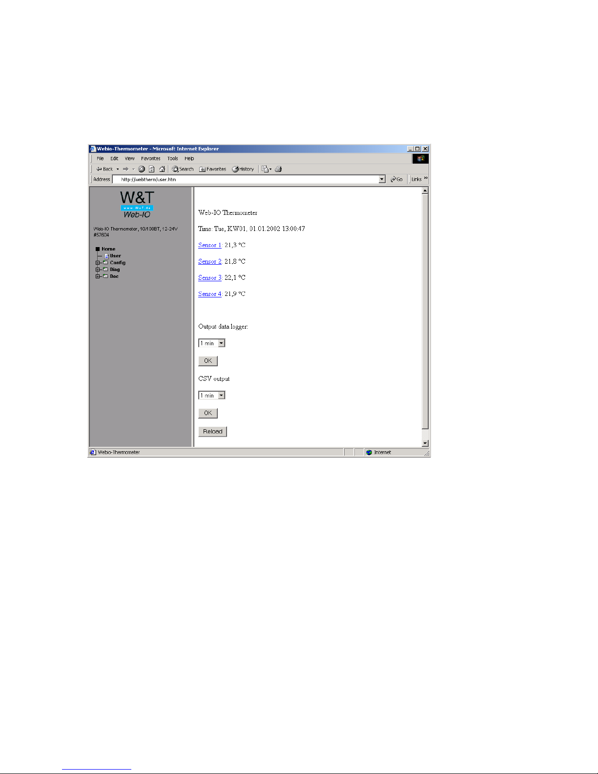
This page is displayed by the Web-IO Thermometer in the Web
browser as follows:
Page 68

W&T
68
Example log.htm:
<log.htm>
<html>
<head>
<title>Untitled Document</title>
<meta http-equiv="Content-Type" content="text/html; charset=iso-8859-1">
</head>
<body bgcolor="#FFFFFF" text="#000000">
<form action="log.htm" method="POST">
<w&t_tags=previous_button>
</form>
<w&t_tags=logtable>
<form action="log.htm" method="POST">
<w&t_tags=next_button>
</form>
</body>
</html>
Page 69
W&T
Subject to errors and modifications
69
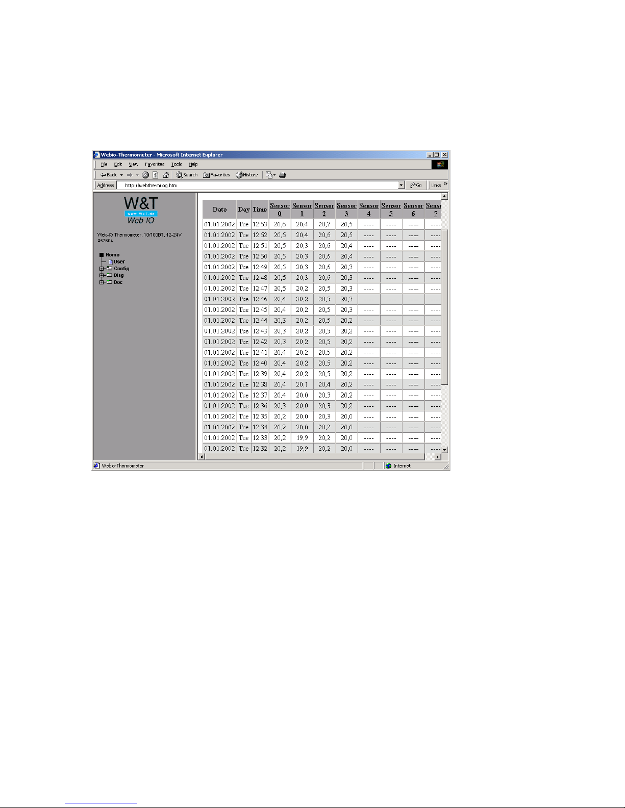
This page is displayed by the Web-IO Thermometer in the Web
browser as follows:
Page 70

W&T
70
7.7 Technical specifications
Article number
Temperature sensor
Network
Supply voltage
Sensing unit
Temperature sensor
Range
Resolution
Measuring error
Memory frequency
Memory depth (64kB)
Other Data
Galvanic isolation
Mail function
Supply voltage
Current Draw
Emergency access
Housing
Weight
Ambient
temperaturestorage
Ambient
temperatureoperating
57601
Web-IO 1x Thermometer
min. 6 weeks, max.
390 weeks
Plastic compact housing
105 x 75 x 22 mm (l x w x h)
non cascaded:
0 ... 60°C
cascaded:
0... 50°C
57603
Web-IO 2x Thermometer
NTC and PT100 connection
10/100BaseT autosensing
12-24V AC/DC, screw terminal block
NTC 10k, PT100 connection, 2-, 3- or 4-wire
-45°C ... 75°C
1/10 °C
+/- 0,3°C, +/- 5% (NTC) +/- 0,3°C, +/- 2% (PT100)
1, 5, 15, 60 min
min. 22 days, max. 195
weeks
Measuring inputs to network: min. 500V
Mail for alarm or as reporting function
DC 12V (-5%) - 34V (+5%)
AC 9V eff (-5%) - 24V eff (+5%)
AVG:170mA @ 12VDC, 80mA @ 24VDC
Serial port RS232, 9600 baud, 8 data bits, 1 stop bit, no parity, no handshake
ca. 200g
-40 ... +70°C
57604
Web-IO 8x Thermometer
min. 5 days, max. 48
weeks
Plastic compact housing, 106.8 x 87.8 x 62.6 mm (l x w x h)
0 ... 60°C
 Loading...