

Page 1

1
Inhalt Seite
1. Einleitung 2
2. Anschluß des LAN Scanner an das LAN 3
3. Überprüfung von Netzwerk-Installationen
im laufenden Betrieb 4
4. History - Funktion 6
5. Wechsel der Batterie 7
Anhang A: Anwendungsbeispiele 8
A.1. Zu lange Kabel 8
A.1.1. Fehlersymptome 8
A.1.2. Messung der Kabellänge 8
A.1.3. Problemlösung 9
A.2. Unterbrechung des Kabels 10
A.2.1. Fehlersymptome 10
A.2.2. Eingrenzung von Fehlern 10
A.3. Vorbeugende Maßnahmen 11
Anhang B: Technische Daten 12
Anleitung
W&T
LAN Scanner
(D/USA)
55504 / 55505
Page 2
2
1. Einleitung
Mit Hilfe des W&T Permanent LAN
Scanner III lassen sich Netzwerkverkabelungen auf ihre Funktionsfähigkeit hin überprüfen.
Der LAN Scanner arbeitet nach dem
Prinzip der TDR - Reflektionsmessung
und erkennt folgende Fehlerbedingungen:
❏ abgezogene Steckverbinder
❏ Kabelbrüche und Unterbrechungen
❏ Kurzschlüsse in Steckverbindern und Kabeln
❏ fehlende Abschlußwiderstände
❏ unzulässige Stichleitungen, etc.
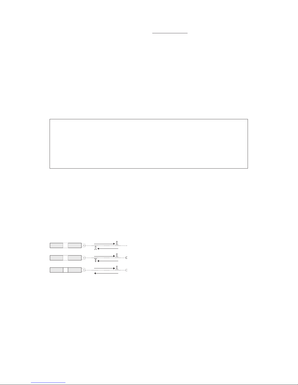
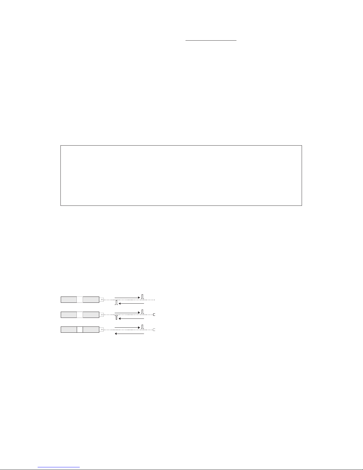
Der LAN Scanner schickt einen kurzen
Impuls (100% kompatibel zu normalen
Netzwerk-Pegeln) auf das Kabel.
Polarität, Amplitude und Laufzeit der
Reflexion geben Aufschluß über einen
Defekt und den entsprechenden Ort
im oder am Ende des Kabels.
Kurzschluß
Offen
richtig
terminiert
reflektierter Impuls
gesendeter Impuls
gesendeter Impuls
gesendeter Impuls
reflektierter Impuls
kein reflektierter Impuls
LAN Scanner Kabel Ende / Fehler
Page 3
3
Die Distanz zwischen dem LAN
Scanner und der fehlerhaften Stelle
wird auf dem LAN Scanner in einem
Zifferndisplay angezeigt.
Damit erlaubt der LAN-Scanner auch
die Messung der Kabellänge.
Mit Ausnahme der Längenbestimmung lassen sich alle Messungen in
Ethernet-Netzwerken bei laufendem
Netzwerk durchführen, da alle
Aktivitäten des LAN Scanners mit
dem Datentransfer auf dem Netzwerk
synchronisiert werden.
Der LAN Scanner arbeitet jedoch nicht
ausschließlich mit Netzwerkkabeln,
sondern prinzipiell mit allen gängigen
Kabeltypen.
2. Anschluß des LAN Scanner an
das LAN:
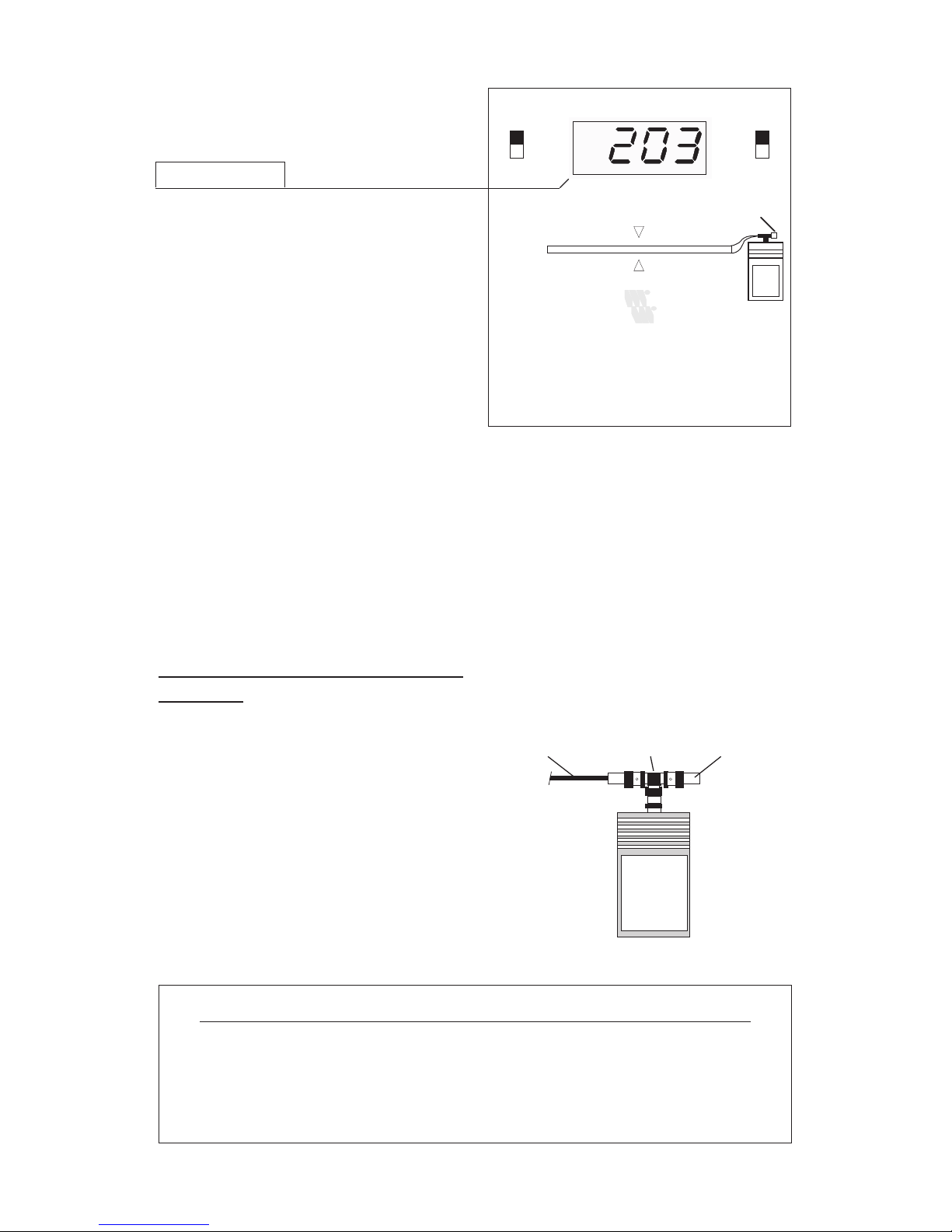
Der Anschluß des LAN Scanner
erfolgt grundsätzlich immer an einem
Ende des LAN-Kabels.
Das testerseitige oder "nahe" Ende
des LAN's muß unter allen Umständen
mit einem Terminator abgeschlossen
werden, das "ferne" Ende des LANKabels je nach Messaufgabe:
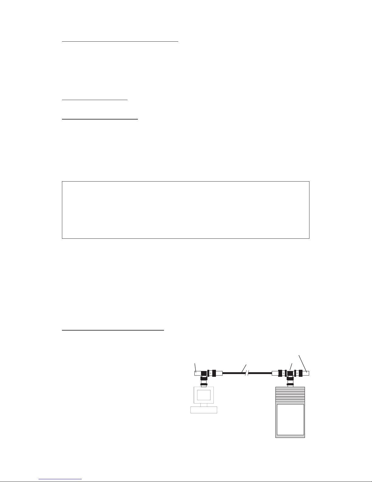
Messung nahes Kabelende fernes Kabelende
Netzwerk-Fehler terminiert terminiert
Netzwerk-Aktivität terminiert terminiert
Segmentlänge terminiert offen
T-Stück TerminatorNetzwerk-Kabel
EAN 40 10344 55504 9W&T LAN Scanner II
short
open
ft
m
off
on
W&T
INTERFACES
Cable
Terminator
Network Activity:
all green lights on.
OK
Page 4
4
Fehlen die Abschlußwiderstände auf
beiden Seiten des Kabelsegments, so
blinkt die rechte LED der LEDBalkenanzeige als Fehleranzeige.
TDR's haben prinzipbedingt mehr oder
weniger große blinde Bereiche, in
denen die Erkennung von Fehlern nicht
möglich ist. Beim W&T LAN Scanner
hat dieser Bereich nur eine
Ausdehnung von ca. 1 Meter.
Zur Überbrückung dieser Distanz
sollte ein 1 Meter langes Meßkabel
zwischen LAN Scanner und
Meßobjekt eingefügt werden.
3. Überprüfung von NetzwerkInstallationen im laufenden Betrieb
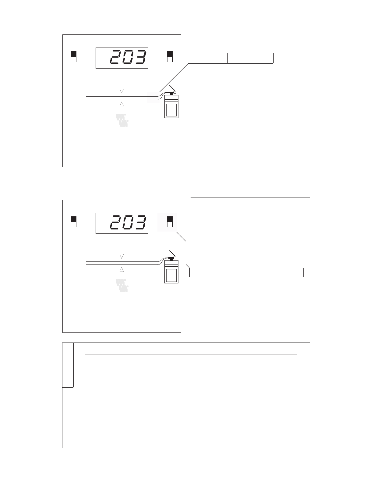
Zur Durchführung der Messung stellen
Sie den Schalter für den Kabeltyp
auf die Signalgeschwindigkeit (NVP)
der von Ihnen verwendeten Kabelsorte
ein und wählen die gewünschte
Anzeigeeinheit (Meter oder Fuß).
Eine Tabelle gängiger LANKabeltypen zur Bestimmung der
Signalgeschwindigkeit für Ihr
spezielles Netzwerkkabel finden Sie
zusätzlich auf der Rückseite des
Gerätes.
Kabeltyp NVP Korrekturfaktor
THIN ETHERNET, PVC (RG 58) 66 1.00
Twinax (RG22 B) 66 1.00
THIN ETHERNET, TFE 70 1.06
10 Base T 74 1.12
THICK ETHERNET, PVC, TFE 78 1.18
TOKEN RING 78 1.18
Antennenkabel (RG 59) 79 1.20
ARCNet, PVC, TFE (RG 62) 84 1.27
Tabelle 1
EAN 40 10344 55504 9W&T LAN Scanner II
short
open
ft
m
off
on
W&T
INTERFACES
Cable
Terminator
Network Activity:
all green lights on.
OK
EAN 40 10344 55504 9W&T LAN Scanner II
short
open
ft
m
off
on
W&T
INTERFACES
Cable
Terminator
Network Activity:
all green lights on.
OK
Page 5
5
Der LAN Scanner 55504 besitzt im
Gegensatz zum Typ 55505 keine
Einstellmöglichkeit für den Kabeltyp.
Bei diesem TDR läßt sich die
gemessene Kabellänge durch
Multiplikation des angezeigten Wertes
mit dem entsprechenden Korrekturfaktor aus Tabelle 1 ermitteln.
Nach dem Einschalten stellt Ihnen der
LAN Scanner innerhalb von 2
Sekunden alle notwendigen Informationen über den aktuellen Status Ihres
Netzwerkkabels zur Verfügung.
Zur Messung sendet der LAN Scanner
während der Pausen im Netzwerkbetrieb einen kurzen elektrischen
Impuls auf das Netzwerkkabel (TDR
- Prinzip).
Eventuelle Reflektionen dieses
Impulses, die von einem fehlerhaften
Abschluß des Netzwerkkabels
herrühren, registriert der LAN Scanner
und bestimmt aus der Signal-Laufzeit
die Entfernung des Störortes.
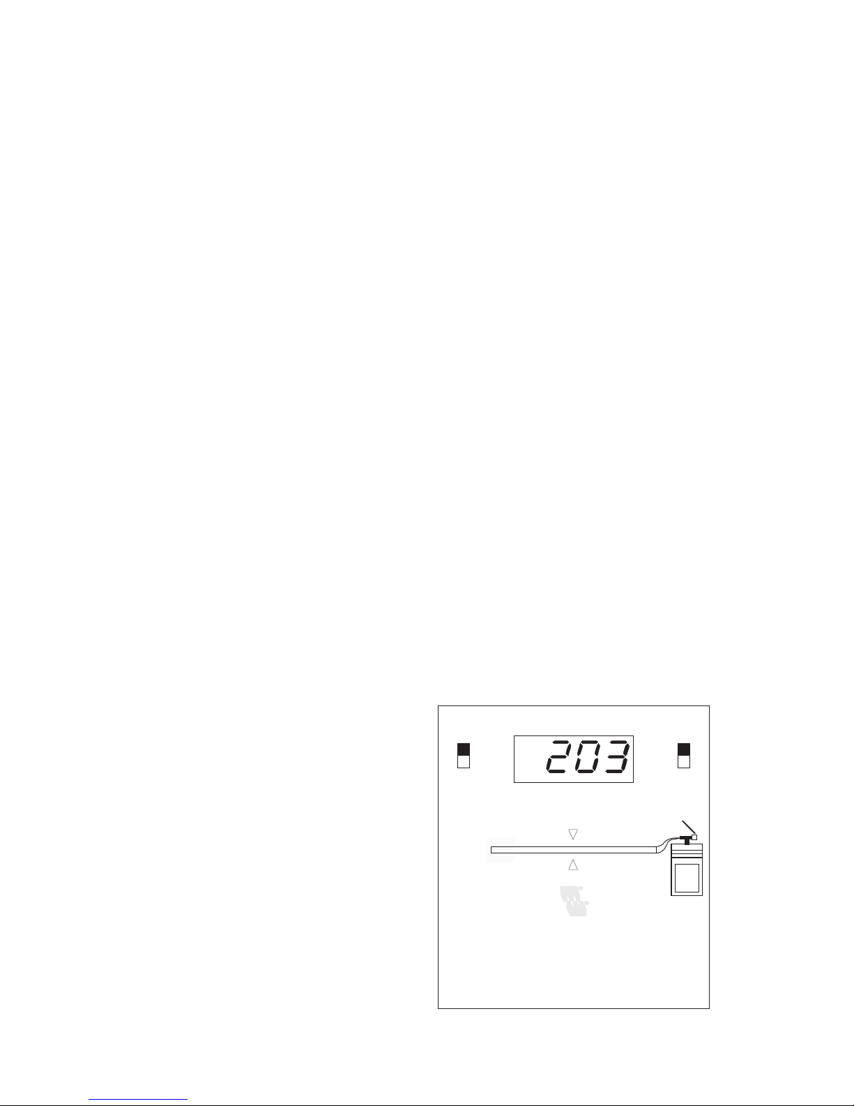
Jeder vom LAN Scanner ausgesandte
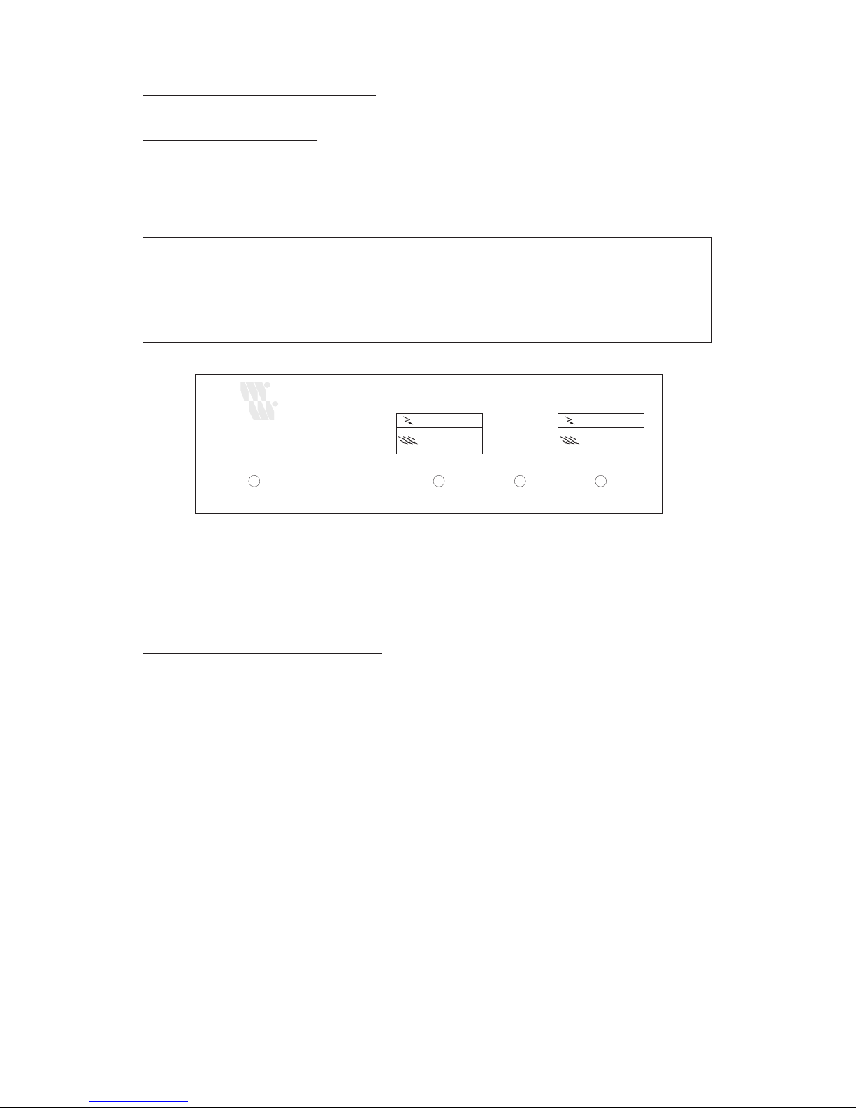
Testimpuls wird auf der LeuchtdiodenBalkenanzeige als laufender Lichtimpuls dargestellt.
Stellt der Tester keine verwertbaren
Reflektionen vom Kabel fest, so läuft
der Lichtimpuls bis zur "OK"- LED
am Ende der LED-Anzeige (analog
zum Testimpuls auf dem Kabel).
EAN 40 10344 55504 9W&T LAN Scanner II
short
open
ft
m
off
on
W&T
INTERFACES
Cable
Terminator
Network Activity:
all green lights on.
OK
Page 6

6
Treten durch fehlerhafte Terminierung
Reflektionen auf der Leitung auf, so
wird mit den LED's "SHORT" und
"OPEN" ein Hinweis auf den
Fehlertyp gegeben (kurzgeschlossenes
oder offenes Kabel).
Im Zifferndisplay wird die Distanz
zwischen LAN Scanner und Störstelle
in Meter oder Fuß angezeigt.
Im Fehlerfall bewegt sich der
Lichtimpuls nur bis zur Mitte der
Leuchtdioden-Balkenanzeige und
läuft zum Ausgangspunkt zurück
(wiederum analog zum reflektierten
Testimpuls auf der Leitung).
In der Zeit außerhalb der Meßphase
werden Netzwerk-Aktivitäten durch
Blinken der gesamten LeuchtdiodenBalkenanzeige im Rhytmus der
Netzwerkpakete angezeigt.
4. History - Funktion (nur 55505)
Um die problemlose Überwachung
eines Ethernet-Netzwerks auf
sporadisch auftretende Fehler über
mehrerere Tage zu ermöglichen,
werden erkannte Fehler nicht nur
angezeigt, sondern zusätzlich in einem
Meßwertspeicher abgelegt.
Maximal 4 Werte können zusätzlich
zum aktuellen Meßwert gespeichert
und mit dem Betriebart-Schalter
(Display Memory/Display Operation)
wieder ausgelesen werden.
EAN 40 10344 55504 9W&T LAN Scanner II
short
open
ft
m
off
on
W&T
INTERFACES
Cable
Terminator
Network Activity:
all green lights on.
OK
EAN 40 10344 55505 6W&T LAN Scanner III
short
open
ft
m
off
on
W&T
INTERFACES
Display
Operation
-1
-2
-3
-4
Display
Memory
Cable
76
78
80
82
84
86
88
90
60
74
62
72
64
70
66
68
Cable Type
(NVP)
Terminator
Network Activity:
all green lights on.
OK
Page 7

7
In Verbindung mit dem zum
Lieferumfang des Tester gehörenden
Netzteil läßt sich mit dieser Funktion
eine Überprüfung eines Ethernet
Netzwerks über einen längeren
Zeitraum realisieren.
5. Wechsel der Batterie
Ein Wechsel der eingebauten LithiumBatterie wird nötig, wenn bei
Tageslicht die grüne LEDBalkenanzeige nicht mehr erkennbar
ist oder trotz korrekter Terminierung
des angeschlossenen Kabels die rechte
LED der Balkenanzeige blinkt
(Hinweis auf unterminiertes Kabel).
Zum Wechsel der Batterie öffnen Sie
bitte das Gehäuse des LAN-Scanners.
Der Gebrauch eines Werkzeugs zum
Öffnen des Gehäuses ist nicht
notwendig.
Biegen Sie von oben die seitliche
Klemmlasche des Gehäuseunterteils
leicht nach außen, bis sich die beiden
Gehäusehälften auf dieser Seite
voneinander trennen lassen.
In der gleichen Weise biegen Sie auf
der Unterseite die Klemmlasche des
Gehäuseoberteils leicht zur Seite.
Ziehen Sie anschließend die beiden
Gehäusehälften auseinander.
Nach Öffnen des Gehäuses können
Sie die alte Batterie entnehmen und
durch eine neue Batterie gleichen Typs
ersetzen.
Page 8
8
Anhang A: Anwendungsbeispiele
Häufigste Ausfall-Ursachen für in Betrieb befindliche Netzwerke sind
erfahrungsgemäß aufgetrennte Steckverbindungen oder zu lange Segmente.
A.1. Zu lange Kabel
A.1.1. Fehlersymptome
Segmentlängen oberhalb der genormten Obergrenzen (Thickwire Ethernet:
500 Meter, Thinwire Ethernet:185 Meter) können die Zuverlässigkeit des
Netzwerkes spürbar verringern.
Zu lange Kabel führen dabei zu folgenden Erscheinungen:
❏ bei geringer Überschreitung der Obergrenze deutlich
verlängerte Zugriffszeiten des Netzwerks
❏ bei großer Verlängerung sporadische, nicht reproduzierbare
Fehlermeldungen, z.B. "Server not found"
Aus diesem Grund ist es bei jeder Neuinstallation eines Netzwerks oder einer
Änderung der bestehenden Verkabelung sinnvoll, die Gesamtlänge des
entstandenen Segments neu zu bestimmen.
A.1.2. Messung der Kabellänge
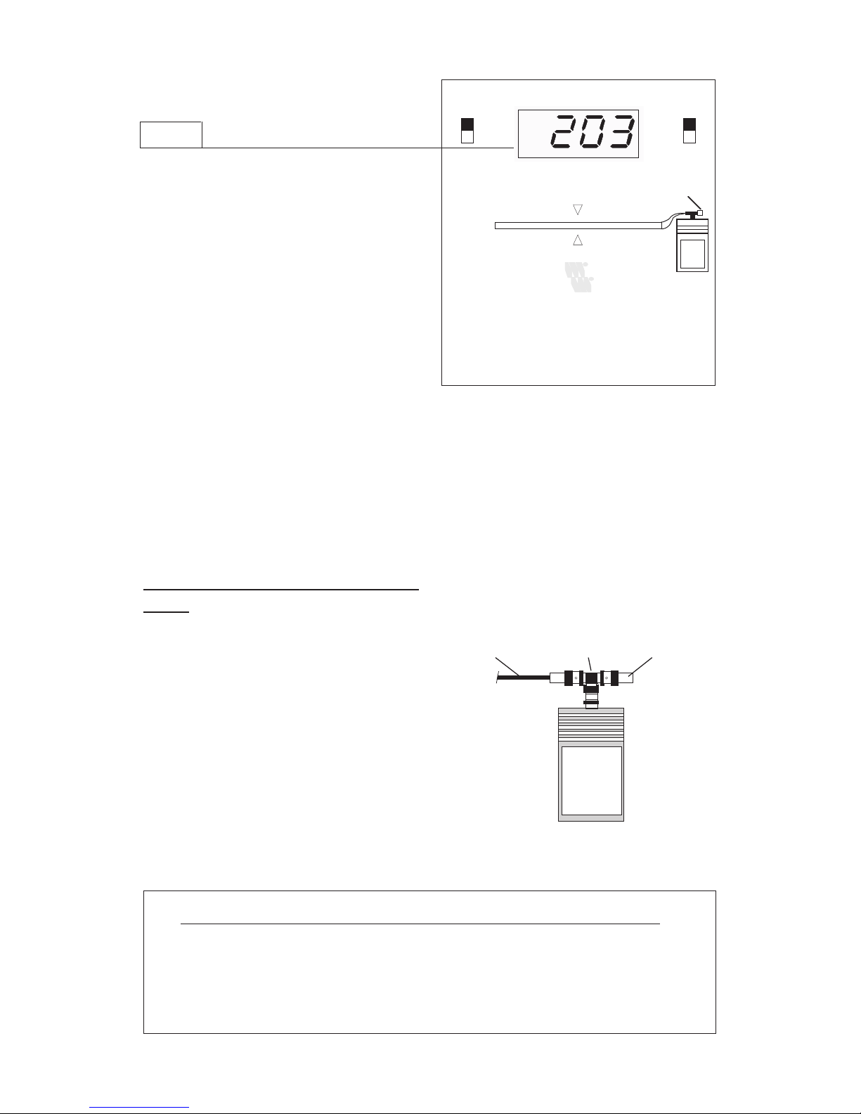
Zur Bestimmung der Segmentlänge
muß der LAN Scannner an ein Ende
des Netzwerkkabels angeschlossen,
und der Abschlußwiderstand am
fernen Ende des Netzwerkkabels
abgenommen werden.
Der LAN Scanner zeigt dann im
Display die Länge des NetzwerkSegments an.
Terminator
T-StückNetzwerk-KabelOffen
Page 9

9
Da bei dieser Messung die
Terminierung des Kabels gestört wird,
ist während der Messung kein
Datenverkehr über das NetzwerkSegment mehr möglich.
A.1.3. Problemlösung
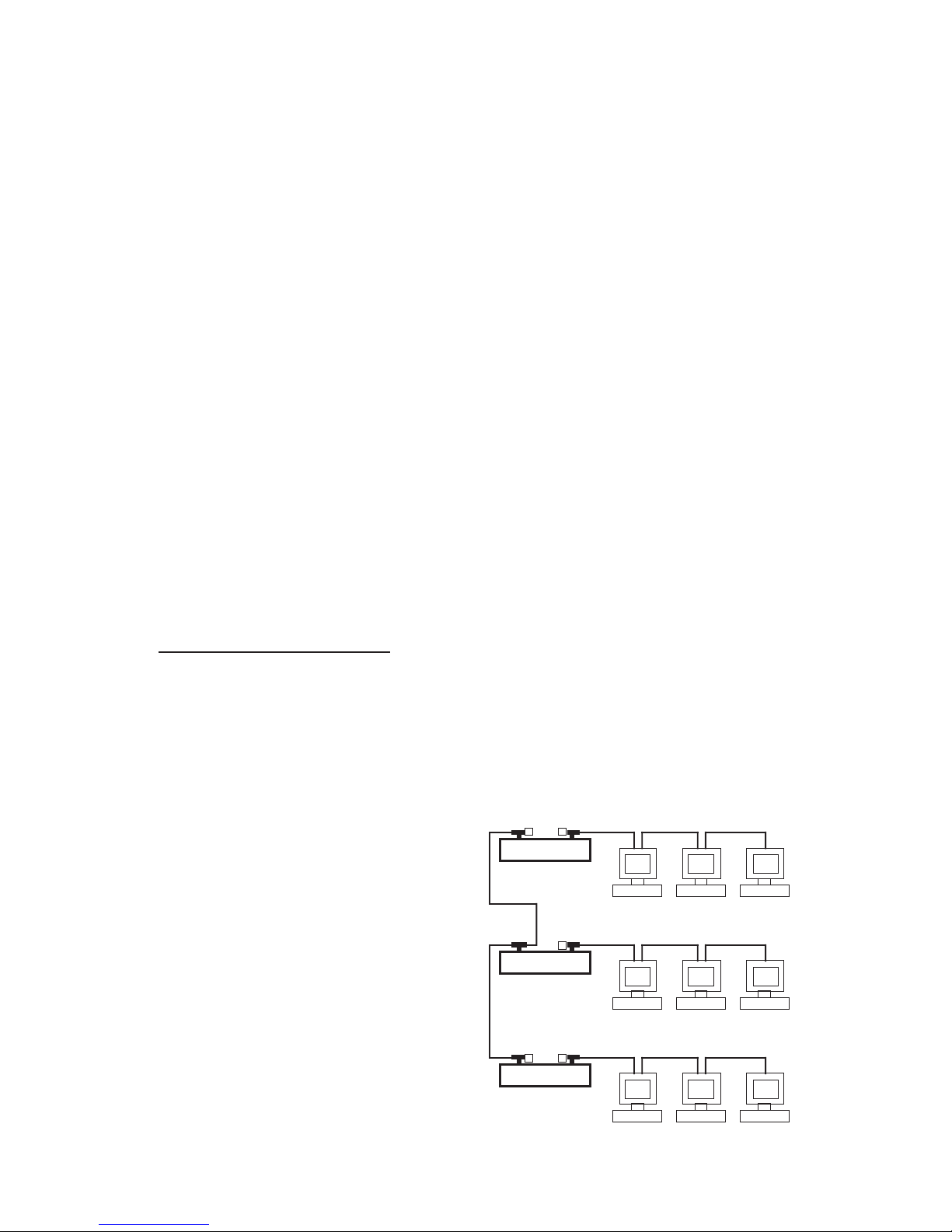
Mit Hilfe der W&T Repeater 55613
und 55615 ist es möglich, die
räumliche Ausdehnung von Thinwire
Ethernet - Netzwerken über die
genormte Obergrenze von 185 m
hinaus zu erweitern.
Repeater verstärken und regenerieren
das Netzwerksignal und erlauben
durch Verbindung mehrerer Segmente
eine Erweiterung der möglichen
Kabellänge.
Zusätzlich läßt sich durch den Einsatz
von Repeatern die Topologie des
Netzes verändern; dies kann z.B durch
Überführung einer busförmigen in
eine baumförmige Struktur zu einer
erheblichen Reduzierung der
notwendigen Kabellänge führen.
Repeater CRepeater C
Repeater CRepeater B
Repeater CRepeater A
Page 10
10
A.2. Unterbrechung des Kabels
A.2.1. Fehlersymptome
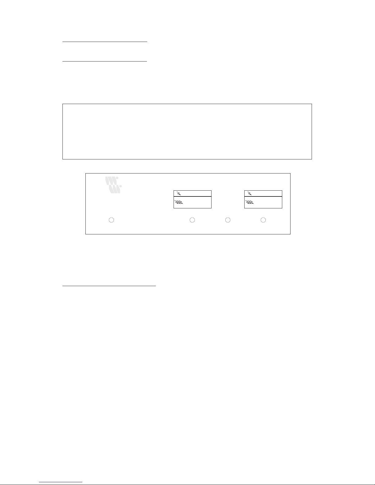
Eindeutige Hinweise auf Unterbrechungen des Netzwerkkabels infolge
aufgetrennter Steckverbindungen oder fehlender Terminatoren sind:
❏ Funktions-Unfähigkeit des kompletten Netzwerk-Segmentes
❏ Leuchten der "Partitioning LED", sowie verstärktes Leuchten
der "Collision LED" eines eventuell eingesetzten Repeaters
A.2.2. Eingrenzung von Fehlern
Die genaue Entfernung der Störstelle von einem Ende des Netzwerkkabels läßt
sich mit der Längenmeßfunktion des LAN Scanners problemlos ermitteln.
Jedoch ist nicht bei allen Netzwerk-Installationen aufgrund dieser
Entfernungsangabe auf Anhieb der Raum zu bestimmen, in dem der Fehler
aufgetreten ist.
Gibt der LAN Scanner z.B. eine Entfernung von 70 Meter zur Störstelle an, so
suchen Sie einen Raum auf, der vermutlich in der angegebenen Entfernung zum
Kabelende liegt.
Trennen Sie eine Steckverbindung des Netzwerkabels in diesem Raum auf, und
bestimmen Sie in beiden Richtungen erneut die Entfernung zur Störstelle.
So läßt sich durch iterative Messungen die Lage der Störstelle auf schnellstem
Wege ermitteln, ohne daß ein Lageplan der Netzwerkverkabelung mit genauen
Längenangaben vorhanden sein muß.
Zur Bestimmung der Störstelle müssen beide Enden des jeweils gemessenen
Kabels mit einem Terminierungswiderstand abgeschlossen sein.
Power COL / Part. B DATA COL / Part. A
EAN 40 10344 55601 5
W&T Thinwire Repeater Box
W&T
INTERFACES
Data Collision
Partitioned:
Segment open or
check Terminator
Data Collision
Partitioned:
Segment open or
check Terminator
Page 11

11
A.3. Vorbeugende Maßnahmen
Da Netzwerkkabel in den meisten Fällen als Bestandteil der übrigen elektrischen
Installation in Kabelkanälen oder über Decken verlegt werden, ist die genaue
Länge der Kabel zwischen Station und Kabelende selten bekannt.
Als vorbeugende Maßnahme ist es daher bei Neuinstallation oder Modifizierung
der Netzwerkverkabelung sinnvoll, eine Liste der effektiven Kabellängen zu
erstellen.
Diese Aufgabe läßt sich auf elegante Weise mit dem LAN Scanner erledigen:
Sie entfernen den Terminator am Ende des Netzwerk-Segments, trennen das
Kabel an der Meßstelle auf, verbinden den LAN Scanner mit angeschlossenem
Terminator mit dem Kabel, und lesen die Länge des Kabels auf dem Meßgerät
ab.
Durch sukzessive Vermessung aller an das Netzwerk angeschlossenen Stationen
erhalten Sie eine genaue Liste der Distanzen zwischen Kabelende und Stationen.
Mit diesem Hilfsmittel läßt sich im Fehlerfall auf Anhieb sagen, in welchem
Raum das Kabel unterbrochen ist.
Page 12

12
Anhang B: Technische Daten 55504 55505
Meßbare Kabellänge: 1 m ... 1000 m 1 m ... 1000 m
(RG 58) (RG 58)
Auflösung: 2m 1m
Meßfehler: +/-3.0 m +/- 1.5 m
Anzahl der Meßwertspeicher: 0 4
Korrekturfaktor für
Signalgeschwindigkeit einstellbar: - 0.6c - 0.9c
Spannungsversorgung:
Batterie: 6 Volt Lithium-Batterie 2 CR 5
Lebensdauer: 40 h Dauerbetrieb
Lagerdauer: 10 Jahre
Netzteil: Steckernetzteil 5 V stab.
(nur beim Typ 55505 im Lieferumfang
enthalten)
Literaturhinweis:
"LAN-Tester und Repeater" aus DATACOM Spezial "Internetworking"
Irrtum und Änderungen vorbehalten. 11/94.
Page 13

13
Contents Page
1. Introduction 14
2. Connection of LAN Scanner to LAN 15
3. Checking Network Installations in
Running Operations 16
4. History - Function 18
5. Battery Change 19
Appendix A: Examples of Usage 20
A.1. Over-long cable 20
A.1.1. Symptoms of Fault 20
A.1.2. Measurement of Cable Length 20
A.1.3. Solution of Problem 21
A.2. Interruption of Cable 22
A.2.1. Symptoms of Fault 22
A.2.2. Localization of Faults 22
A.3. Preventive Measures 23
Appendix B: Technical Data 24
Instructions
W&T
LAN Scanner
55504 / 55505
Page 14
14
1. Introduction
Network cable functions can be
checked by means of a W&T
Permanent LAN Scanner III. The LAN
Scanner works on the principle of the
TDR reflection measurement and
recognizes the following faults:
❏ dislocated barrel connector
❏ cable break or interruption
❏ short in barrel connector or cable
❏ missing terminator
❏ unacceptable branch cable
The LAN Scanner sends a short pulse
(100% compatible with the standard
network levels) on the cable.
Polarity, amplitude and duration of
the reflected pulse give information
on any fault and on the corresponding
position in or at the end of the cable.
short
open
properly
terminated
Reflected Pulse
Transmitted Pulse
Transmitted Pulse
Transmitted Pulse
Reflected Pulse
No Reflected Pulse
LAN Scanner Cable End or Fault
Page 15
15
The distance between the LAN scanner
and the fault is shown on the numeral
display of the LAN Scanner.
This allows the LAN Scanner to
measure the cable length.
With the exception of the
determination of the length, all other
measurements of the Ethernet network
can be carried out while the network is
operating, as all activities of the LAN
Scanner can be synchronized with the
data transfer on the network.
The LAN Scanner, however, does not
work exclusively with network cables
but also with all usual types of cables.
2. Connection of LAN Scanner to
LAN:
The LAN Scanner is always connected
to one end of the LAN cable.
In every case, the test-side or "near"
end of the LAN must be closed with a
terminator, the "far" end of the lAN
cable is dependent on the measurement
task:
Measurement near cable end far cable end
network fault terminated terminated
network activity terminated terminated
segment length terminated open
Tee TerminatorNetwork Cable
EAN 40 10344 55504 9W&T LAN Scanner II
short
open
ft
m
off
on
W&T
INTERFACES
Cable
Terminator
Network Activity:
all green lights on.
OK
Page 16
16
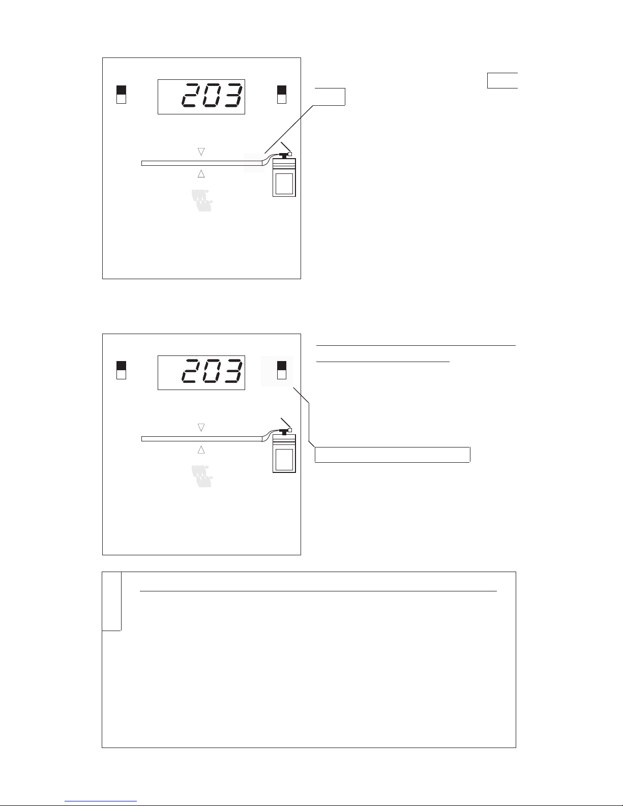
If the terminators are missing on both
ends of the cable segments, the right
LED on the LED bar display blinks to
display the fault.
Principally, TDRs have lesser or
greater blind spots where faults cannot
be recognized. The W&T LAN
Scanner has a blind spot of only 1
metre.
In order to bridge this distance, a
measuring cable of 1 metre in length
should be inserted between the LAN
Scanner and the object to be measured.
3. Checking Network Installations
in Running Operations
In order to carry out th measurements,
adjust the switch for the cable type to
the signal speed (NVP) of the cable
you are using and choose the desired
display unit (metre or foot).
In addition, you will find a table of the
common LAN cable types which
determine the signal speed for your
particular network cable on the rear
side of your appliance.
cable type NVP correction faktor
THIN ETHERNET, PVC (RG 58) 66 1.00
Twinax (RG22 B) 66 1.00
THIN ETHERNET, TFE 70 1.06
10 Base T 74 1.12
THICK ETHERNET, PVC, TFE 78 1.18
TOKEN RING 78 1.18
antenna cable (RG 59) 79 1.20
ARCNet, PVC, TFE (RG 62) 84 1.27
Table 1
EAN 40 10344 55504 9W&T LAN Scanner II
short
open
ft
m
off
on
W&T
INTERFACES
Cable
Terminator
Network Activity:
all green lights on.
OK
EAN 40 10344 55504 9W&T LAN Scanner II
short
open
ft
m
off
on
W&T
INTERFACES
Cable
Terminator
Network Activity:
all green lights on.
OK
Page 17
17
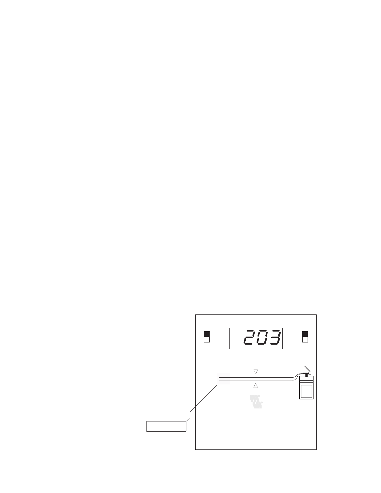
In comparison to type 55505, the LAN
Scanner 55504 has no adjustment
device for cable types. With this TDR,
the measured length of cable can be
determined by multiplying the
displayed value by the corresponding
correction factor in table 1.
After being switched on , the LAN
Scanner provides you with all
necessary information on the current
status of your network cable within 2
seconds.
The LAN Scanner carries out the
measurements by sending a short
electrical impulse through the network
cable (TDR principle) during pauses
in network operations.
Possible reflections of these impulses
arising from a faulty termination of
the network cable are registered by the
LAN Scanner and measure the distance
to the location of the fault by
determining the time required to
receive the signal.
Each test impulse transmitted by the
LAN Scanner is shown on the lightemmiting diode bar display as a
continuous light impulse.
If the tester does not register any
measurable reflections from the cable,
the light impulse runs to "OK"-LED
at the end of the LED display (analogue
to the test impulse on the cable).
EAN 40 10344 55504 9W&T LAN Scanner II
short
open
ft
m
off
on
W&T
INTERFACES
Cable
Terminator
Network Activity:
all green lights on.
OK
Page 18
18
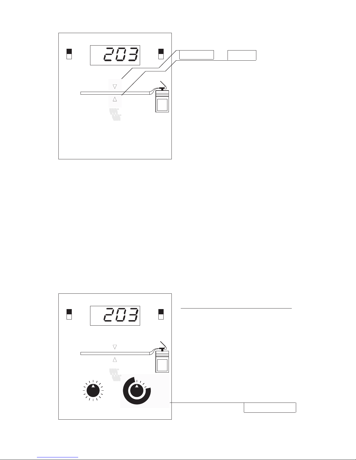
If reflections due to faulty terminators
occur on the conductor, the LED's
"SHORT" and "OPEN" will provide
an indication of the type of fault
(shorted or open cable).
The distance between the LAN
Scanner and the location of the fault is
shown in metres or feet on the numeral
display.
In the case of a fault, the light impulse
only moves to the center of the LEDchain and runs back to the starting
point (again, analogue to the reflected
test impulse on the conductor).
In the period outside the measurement
phase, the network activities are shown
by the whole bar graphic display
blinking in rhythm to the network
package.
4. History - Function (only 55505)
In order to avoid problems when
checking the Ethernet network for
sporadic faults over a period of several
days, registered faults are not only
displayed but also stored in a data
memory.
In addition to the current data, a
maximum of 4 values can be stored
and recalled with the operation switch
(Display Memory/Display Operation).
EAN 40 10344 55505 6W&T LAN Scanner III
short
open
ft
m
off
on
W&T
INTERFACES
Display
Operation
-1
-2
-3
-4
Display
Memory
Cable
76
78
80
82
84
86
88
90
60
74
62
72
64
70
66
68
Cable Type
(NVP)
Terminator
Network Activity:
all green lights on.
OK
EAN 40 10344 55504 9W&T LAN Scanner II
short
open
ft
m
off
on
W&T
INTERFACES
Cable
Terminator
Network Activity:
all green lights on.
OK
Page 19

19
Due to the function of the mains supply
circuit which is part of the package
delivered with the tester, the Ethernet
network can be checked over a longer
period of time.
5. Battery Change
It is necessary to change the in-built
lithium battery when the green LED
bar display can no longer be read in
daylight or when the right LED of the
bar display blinks in spite of the correct
termination of the connected cable
(indication of undermined cable).
In order to change the battery, open
the casing of the LAN Scanner. It is
not necessary to use a tool to open the
casing.
From the top, slightly bend the side
clamping lug on the bottom part of the
casing in an outward direction until
both halves of the casing can be
separated from each other at this point.
In the same manner, slightly bend the
clamping lug on the underside of the
top part of the casing in a sidewards
direction.
finally, pull both casing halves apart.
After opening the casing, the old
batteries can be removed and replaced
by new batteries of the same type.
Page 20
20
Appendix A: Examples of Usage
The most common causes of breakdowns in networks which are in operation
are, in our exerience, broken barrel connectors or over-long segments.
A.1. Over-long cable
A.1.1. Symptoms of Fault
Segment lengths over the standard maximum limit (Thickwire Ethernet: 500
metres, Thinwire Ethernet: 185 metres) can noticeably reduce the reliability of
the network.
Over-long cables can result in the following complications:
❏ noticeable increased access times to the network when the
maximal limit is only slightly exceeded.
❏ sporadic, non-reproducible registration of faults, e.g. "Server
not found" when the limit is further exceeded.
For this reason, it is useful to re-determine the total length of the resulting
segment when a network is first installed or when existing networks are
changed.
A.1.2. Measurement of Cable Length
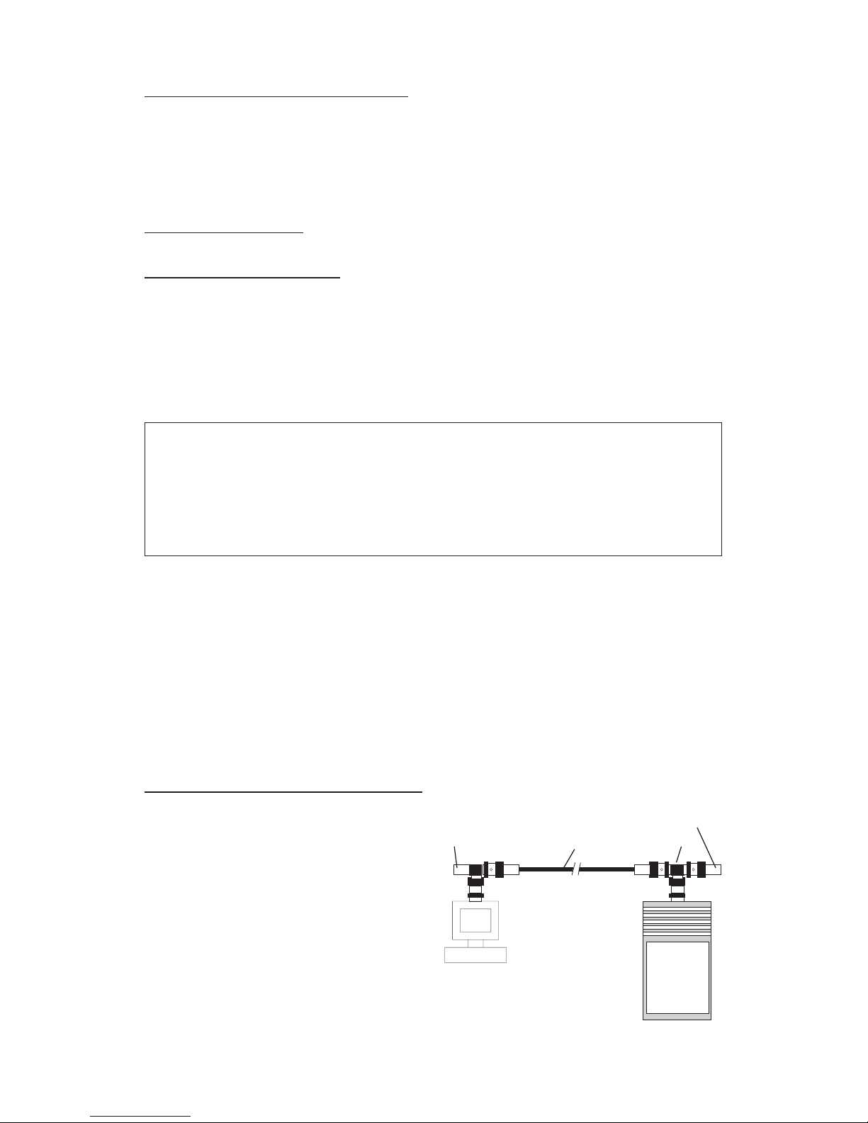
In order to determine the length of the
segment, the LAN Scanner must be
connected to one end of the network
cable, and the terminator on the far
end of the network cable must be
removed.
The LAN Scanner display then shows
the length of the network segment.
Terminator
TeeNetwork CableOpen
Page 21
21
Because the termination of the cable
can be interrupted during this
measurement, data cannot be
transferred via the network segment
while the measurements are being
carried out.
A.1.3. Solution of Problems
With the help of the W&T Repeater
55613 or 55615, it is possible to extend
the length of thinwire Ethernet
networks beyond the standard
maximum limit of 185 metres.
Repeaters strengthen and regenerate
the network signal and allow an
extension of possible cable lengths by
connecting several segments.
In addition, the topology of the network
can be changed through the use of
repeaters; this can result in a
considerable reduction of essential
cable lengths, for example, by
transferring a bus-formed structure
into a tree-formed one.
Repeater CRepeater C
Repeater CRepeater B
Repeater CRepeater A
Page 22
22
A.2. Interruption of Cable
A.2.1. Symptoms of Fault
Clear indication of an interruption of the network cable as a result of dislocated
barrel connectors or missing terminators are:
❏ function breakdown of total network segment
❏ illumination of "Partitioning LED", as well as increased
illumination of the "Collision LED" on the repeater which
may be in operation.
A.2.2. Localization of Faults
The exact distance of the location of the fault from one end of the network cable
can be easily determined by the length measurement function of the LAN
Scanner.
However, it is not always possible with every network installation to immediately
determine the room in which the fault has ocurred.
For example, if the LAN Scanner shows a distance of 70 metres to the location
of the fault, choose a room which is probably at this given distance from the end
of the cable.
Dislocate one of the barrel connectors on the network in this room, and, once
again, determine the distance to the location of the fault in both directions.
By means of these iterative measurements, it is possible to determine the
location of the fault very quickly without having a plan of the network cables
giving the exact cable lengths.
In order to determine the location of the fault, both ends of each cable to be
measured must be closed with a terminator resistor.
Power COL / Part. B DATA COL / Part. A
EAN 40 10344 55601 5
W&T Thinwire Repeater Box
W&T
INTERFACES
Data Collision
Partitioned:
Segment open or
check Terminator
Data Collision
Partitioned:
Segment open or
check Terminator
Page 23

23
A.3. Preventive Measures
In most cases, the network cable is laid as part of the usual electrical installation
in the cable canals or above the ceilings, an so the exact length of cable between
station and cable end is rarely known.
For this reason, it is advisable to write a list of the effective cable lengths as a
precautionary measure when first installing or modifying network cables.
This task can be done very elegantly with the LAN Scanner: Remove the
terminator from the end of the network segment, open up the cable at the point
of measurement, connect the LAN Scanner with connected terminator to the
cable, and read the length of the cable shown on the measuring device.
By successive measurements of all stations connected to the network, you will
have an exact list of the distances between the cable ends and the stations. By
this method, it becomes possible to immediately determine the room in which
the cable has been interrupted.
Page 24

24
Appendix B: Technical Data 55504 55505
measurable cable length: 3' ... 3,300' 3' ... 3,300'
(RG 58) (RG 58)
dissolution: 6' 3'
error of measurement: +/- 9' +/- 5'
number of data memorys: 0 4
correction faktor for
signal speed adjustable: - 0.6c - 0.9c
power supply:
battery: 6 volt lithium battery 2 CR 5
service life: 40 h continuous operations
storage life: 10 years
mains supply circuit: plug circuit 5 V rod
(only contained in type 55505 delivery
package)
 Loading...