

Page 1

W&T
Manual
USB-Server
Model 53641 (Beta-Version)
Release 1.02, March 2010
Page 2

W&T
© 11/2009 by Wiesemann und Theis GmbH
Microsoft, MS-DOS, Windows, Winsock and Visual Basic
are registered trademarks of Microsoft Corporation
Subject to errors and changes:
Since mistakes are always possible, all of the information in this
manual should be applied with discretion. Please let us know of
any errors or unclear instructions so that we can correct them
as quickly as possible.
Perform work on and with W&T products only as described here
and after you have read and understood the manual in full.
Unauthorized actions may create hazardous conditions. We are
not liable for the consequences of unauthorized actions. When
in doubt, please consult with us or your dealer.
Page 3

W&T
This device contains software components which are subject
to one or more Open Source licenses. The Appendix to this
document contains copies of these licenses.
The associated source text can be downloaded at no charge
from:
http://www.wut.de/e.5wwww-60-inus-000.php
You may also obtain the source code from us in the form of a
data medium for a period of three years after the last product
shipment for a nominal charge. To avail yourself of this offer,
please contact us at [email protected].
This offer is valid for every recipient of this notification.
Page 4

4
W&T
Content
1 Quickstart ................................................................. 7
Step 1: Installation ................................................................ 8
Step 2: Power and network connection ................................... 9
Step 3: Connecting the USB devices ..................................... 10
Step 4: Setting the network parameters ................................. 11
Step 5: Installing the W&T USB Port Redirector ....................... 12
Step 6: Connecting to a USB device ...................................... 13
2 System Overview and Function ............................... 15
2.1 Introduction to the W&T USB-Server ........................... 16
2.1.1 Supported USB modes .............................................. 16
2.1.2 Maximum number of USB devices .............................. 16
2.1.3 System overview ...................................................... 17
3 Assigning/Changing IP Parameters ....................... 19
3.1 Managing the network parameters in the USB-Server ... 20
3.2 DHCP mode (factory default setting).......................... 21
3.2.1 Activating DHCP mode ............................................. 21
3.2.2 Deactivating DHCP mode .......................................... 22
3.2.3 System Name ........................................................... 23
3.2.4 Lease time ............................................................... 23
3.2.5 Reserved IP addresses .............................................. 24
3.2.6 Dynamic IP addresses ............................................... 24
3.3 Static mode ............................................................. 26
3.3.1 Assigning static IP parameters using WuTility ............. 26
3.3.2 Assigning static IP parameters using WBM .................. 28
4 Hardware - Interfaces and Indicators ...................... 31
4.1 Supply voltage ......................................................... 32
4.1.1 PoE supply ............................................................... 32
4.1.2 External supply ........................................................ 32
4.2 Ethernet port ........................................................... 33
4.2.1 10/100BaseT to RJ45 ................................................ 33
4.3 USB ports ................................................................ 35
4.4 LED indicators .......................................................... 36
Page 5

5
W&T
Subject to errors and modifications
5 The W&T USB Port Redirector .................................. 39
5.1 Overview ................................................................. 40
5.1.1 Port numbers ........................................................... 40
5.2 Installation/Deinstallation of the USB Redirector ......... 42
5.2.1 Installation from the product CD ............................... 42
5.2.2 Installation from download ....................................... 43
5.2.3 Uninstalling ............................................................. 43
5.3 The inventory list ..................................................... 44
5.3.1 Automatic inventory list creation ............................... 45
5.3.2 Manual entries in the configuration list ...................... 45
5.3.3 Saving and opening inventory lists ............................ 46
5.4 Using USB devices - Plug/Unplug .............................. 47
5.4.1 System response / conflict protection ....................... 47
5.4.2 Adding a USB device - Plug ....................................... 47
5.4.3 Closing a connection - Unplug .................................. 48
6 Web-Based-Management .......................................... 49
6.1 Starting and navigating the WBM ............................... 50
6.1.1 Navigation concept of the USB-Server ........................ 50
6.1.2 The Start page of the USB-Server ................................ 51
6.2 WBM - configuration sessions ................................... 52
6.3 WBM - Assigning passwords ...................................... 54
6.4 WBM - Network basic parameters ............................... 55
7 Appendix ................................................................ 59
7.1 Up- and downloading configuration data ................... 60
7.1.1 Up- and downloading the configuration using WBM .... 60
7.1.2 Up- and downloading using WuTility ......................... 61
7.2 Firmware update ...................................................... 62
7.2.1 Where is the current firmware available? ..................... 62
7.2.2 Firmware update under Windows ............................... 62
7.3 Resetting the USB-Server ........................................... 64
7.4 Reset to factory defaults ........................................... 65
7.4.1 Hardware reset to factory default settings .................. 65
7.4.2 Software reset to factory default settings ................... 65
7.5 Used ports and network security ............................... 66
7.6 Technical data ......................................................... 69
7.7 Licences .................................................................. 70
Index .......................................................................... 78
Page 6

6
W&T
Page 7

7
W&T
Subject to errors and modifications
1 Quickstart
Those who are already familiar with use of the W&T USB-Server will find on
the following pages a quick start procedure with the basic steps from
hardware installation to IP assignment and starting the Windows driver.
Additional information is contained in the respective detail sections.
Page 8
8
W&T Quickstart
Step 1: Installation
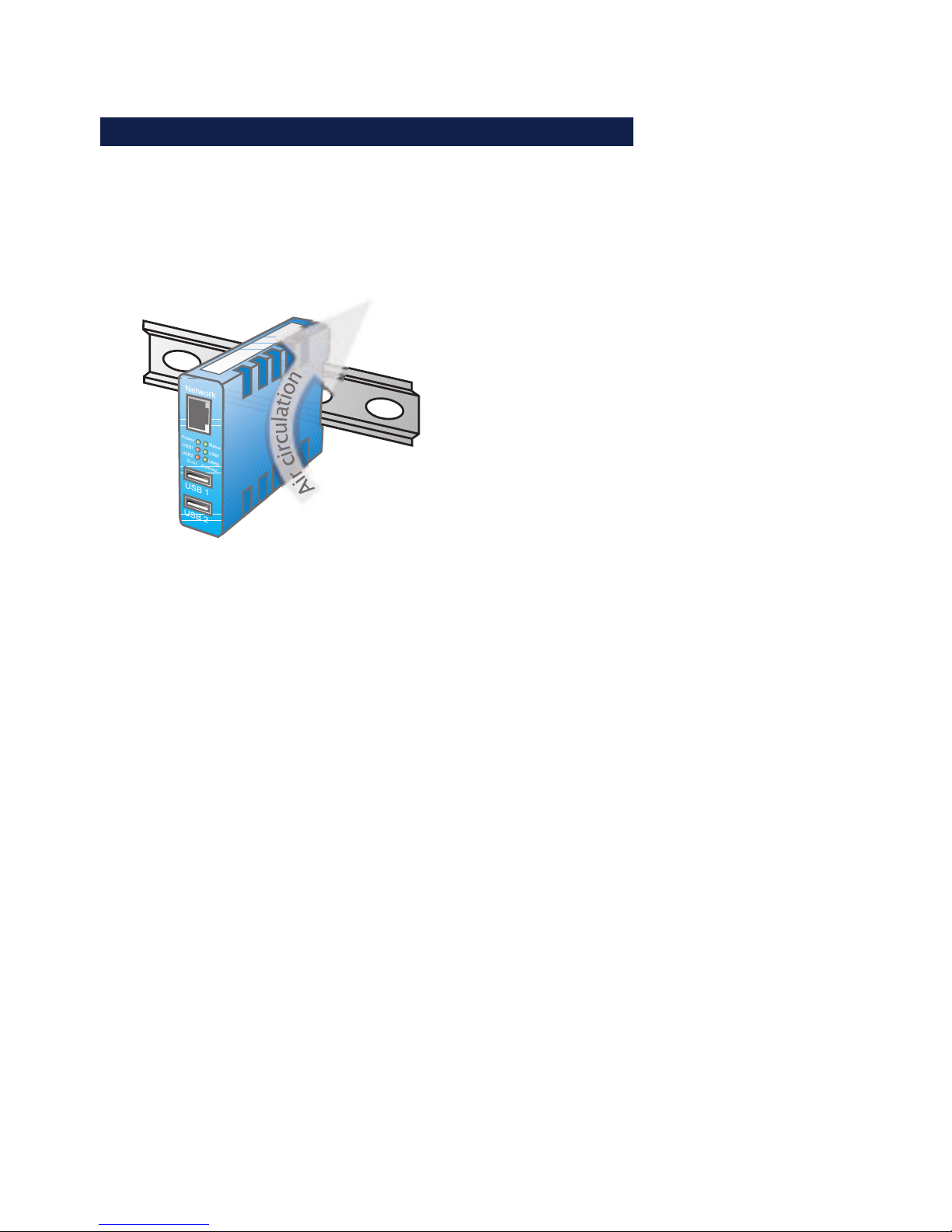
The housing of the W&T USB-Server and the arrangement of the
ventilation slot is designed for installation on a standard DIN
rail per DIN EN 50022-35.
1
Especially in local conditions at elevated temperatures
any alternate method of mounting must still ensure
adequate air circulation.
Page 9
9
Subject to errors and modifications
W&T Quickstart
Step 2: Power and network connection
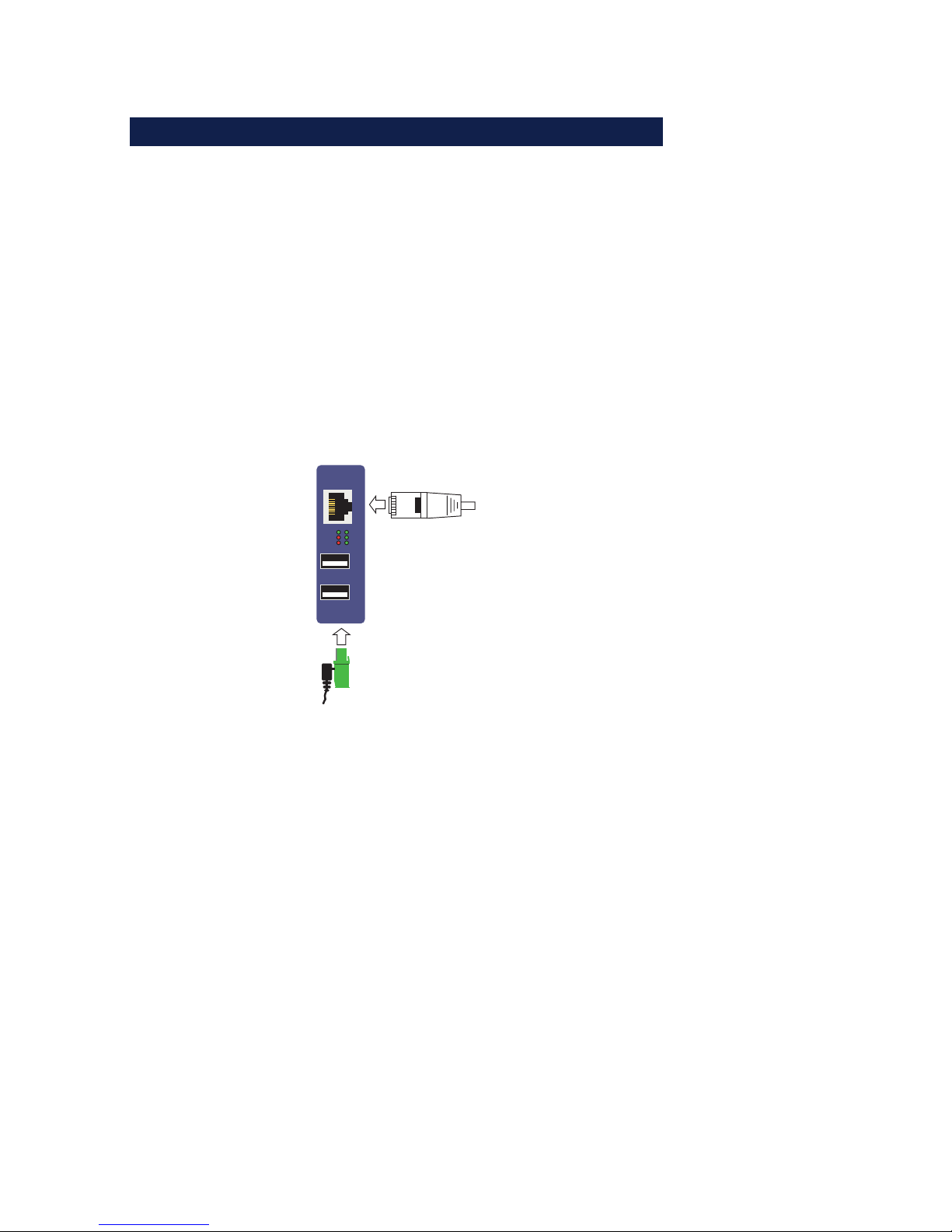
Power-over-Ethernet
When PoE is used (IEEE802.3af) power for the W&T USB-Server
is provided by the network infrastructure, so that simply
connecting the network cable is all that is required.
Using an external power supply
Alternately power can be brought in externally to the screw terminal located on the underneath of the device. The wide-range
input of the USB-Server allows use of DC voltage from +24 +48V. The input is reverse polarity protected, i.e. the polarity of
the supply voltage is not critical.
Error
USB 1
USB 2
USB 2
USB 1
Connect
PowerStatus
USB 2
USB 1
Network
Presence of the correct voltage is indicated by the Power LED.
Network connection
Connection to the 10/100BaseT network is accomplished using
a 1:1 wired, standard RJ45 patch cable. If a link can be
established with the switch, this is indicated by illumination of
the green Status LED.
1
Detailed information about the supply voltage and the
network connection of the W&T USB-Server can be found
in the Hardware section.
Page 10
10
W&T Quickstart
Step 3: Connecting the USB devices
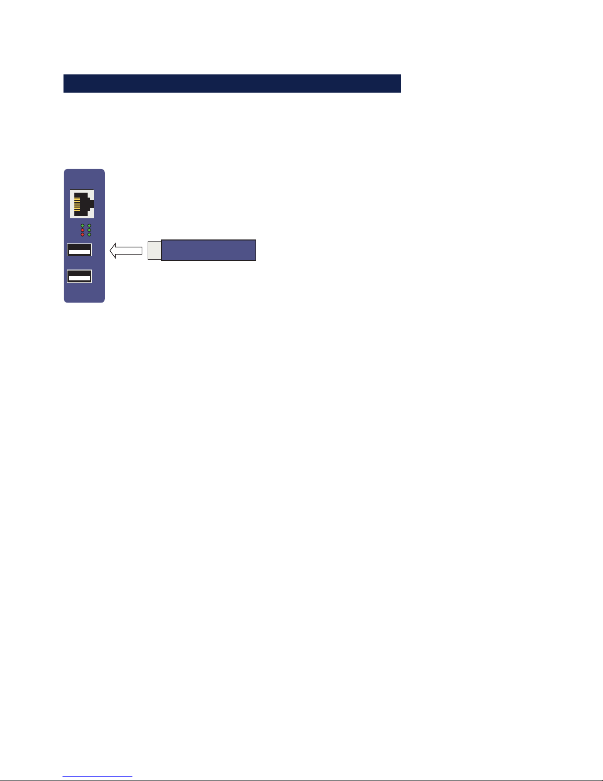
The W&T USB-Server provides two USB 2.0 ports for connecting
USB devices. The ports are capable of providing max. 500mA
each for supplying the connected devices.
USB device
(e.g. USB stick)
Error
USB 1
USB 2
USB 2
USB 1
Connect
USB 2
USB 1
Network
PowerStatus
LED USBx Error
The LEDs indicate overload or a short circuit on the respective
USB port. The supply voltage to the affected USB port is turned
off and the connected device is disabled.
LED USBx Connect
The LED indicates an active connection to a W&T USB Port
Redirector located in the network.
1
Detailed information about the USB connections
of the W&T USB-Server can be found in the Hardware
section.
Page 11

11
Subject to errors and modifications
W&T Quickstart
Step 4: Setting the network parameters
The default address of the W&T USB-Server is:
190.107.233.110
In addition, DHCP protocol is the factory default. If the network
in question has a DHCP server, the network basic parameters
are automatically assigned after powering up the W&T USB-Ser-
ver and after it is connected to the network.
Alternately the WuTility inventory and management tool can be
used to switch to static network parameters. Install this tool on
a Windows PC from the included product CD; the PC must be
located in the same subnet as the W&T USB-Server.
After starting, WuTility automatically searches the network for
accessible W&T network devices. Select from the list of found
devices the desired W&T USB-Server and then click on the IP
Address button.
The following dialog allows you to switch to Static mode for
manually assigning the IP address, subnet mask and gateway.
Activating Static mode automatically deactivates DHCP
protocol.
1
Detailed information about the various methods of
assigning the IP address is found in the Assigning the IP
address section.
Page 12

12
W&T Quickstart
Step 5: Installing the W&T USB Port Redirector
The W&T USB Port Redirector implemented as a Windows core
driver makes a virtual USB host controller available. Install it on
a Windows XP or higher machine using the W&T product CD
included in the scope of delivery. Login as Administrator or
with administrator rights is required for installation.
After starting the W&T product CD, the link Search is located
on the USB-Server tab. In the following dialog select the 32- or
64-bit version as required by your system and then click on the
Install/Uninstall button. In addition to the actual core driver the
associated configuration and management tool is also installed
in the new program group W&T USB Port Redirector.
1
To make it possible to publish updates to the W&T USB
Redirector as soon as possible, the driver is not WHQL
certified. To successfully finish the installation the
corresponding message from the Windows logo test must be
acknowledged with Continue installation.
1
Detailed information about installing is found in the W&T
USB Port Redirector section.
Page 13
13
Subject to errors and modifications
W&T Quickstart
Step 6: Connecting to a USB device
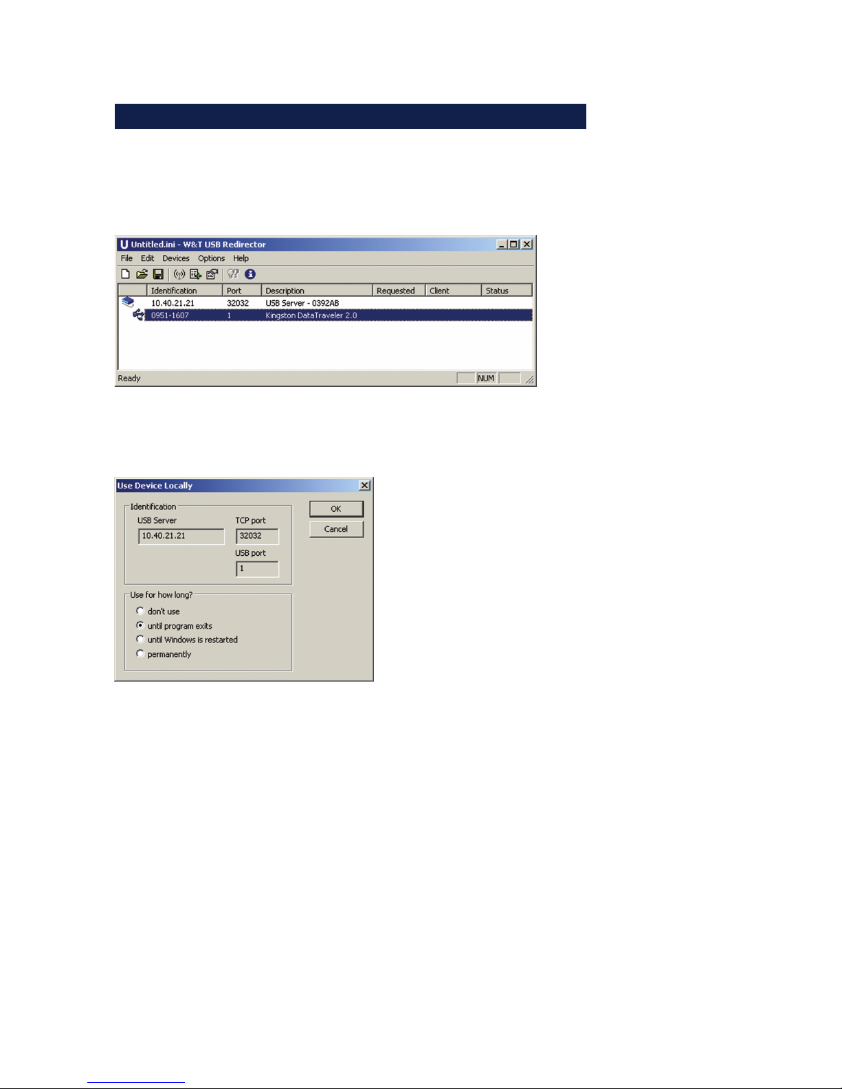
The configuration tool is started from the new program group
W&T USB Port Redirector. The local subnet is automatically
searched for by W&T USB Servers and connected USB devices.
Double-clicking on the desired device results in the following
dialog.
In addition to the three options for duration, any existing
connection can also be closed here.
• Dont’ use
Quits any existing connection to a USB device so that it can
be used by other systems.
• Until program exits
The USB device remains logged on in the system until the
configuration tool is closed.
• Until Windows is restarted
The USB device remains logged on in the system even after
the configuration tool is closed. It is not logged off until
Windows is restarted. D
Page 14

14
W&T Quickstart
• Permanently
The USB device is permanently logged on in the system. This
means that after a computer restart the connection is
automatically restored and the USB device logged on in the
system.
Like when plugging in to a local USB port, clicking the OK
button adds the USB device to the WIndows plug&play system.
The device-specific driver installation than then be used as if it
were connected to a local USB port on the computer.
If the Windows computer and the W&T USB-Server are not
located in the same subnet, no automatic inventorying can take
place. The W&T USB-Server must first be manually added using
Device r Add.
1
Detailed information on the function of the W&T USB Port
Redirector is found in the W&T USB Port Redirector
section.
Page 15

15
W&T
Subject to errors and modifications
2 System Overview and Function
The W&T USB-Server together with the W&T USB Port Redirector provides a
transparent network tunnel for sending USB datagrams.
. Data connection concept
. Virtual USB-Host-Controller
Page 16

16
W&T System Overview
2.1 Introduction to the W&T USB-Server
The W&T USB-Server in conjunction with the computer-side
in W&T USB Port Redirector enables the addition of remote USB
devices located in the network. With respect to the devicespecific drivers and applications these behave as if they were
connected to a local USB port on the computer.
2.1.1 Supported USB modes
The W&T USB-Server conforms with USB 1.0, 1.1 and 2.0 with
transmission speeds of 1.5 Mbit/s (Low), 12 Mbit/s (Full) and
480 Mbit/s (High). This means most USB devices using the
transfer modes Control, Interrupt and Bulk are supported.
Isochronal mode, which is used mainly in audio and video
applications, is in development.
Due to the complex interaction between operating system,
often multiple driver instances and the respective hardware, USB
applications are in practice not always plug&play. W&T
therefore offers the service of a compatibility check of your USB
device together with the W&T USB-Server. For additional
information, see our Web site at http://www.wut.de/53641.
2.1.2 Maximum number of USB devices
Although the W&T USB-Server is designed for direct connection
of two USB devices, connection of an external USB hub per USB
port is also supported. This allows max. 8 USB devices to be
connected and incorporated through the W&T USB Port
Redirector into Windows systems. It should be noted however
that multi-function devices do often already have internal hubs.
Page 17

17
Subject to errors and modifications
W&T System Overview
1
With respect to data throughput - especially when
connecting High-Speed USB devices - it must be
remembered that only a theoretical bandwidth of maximum
100Mbis/s is available on the network side.
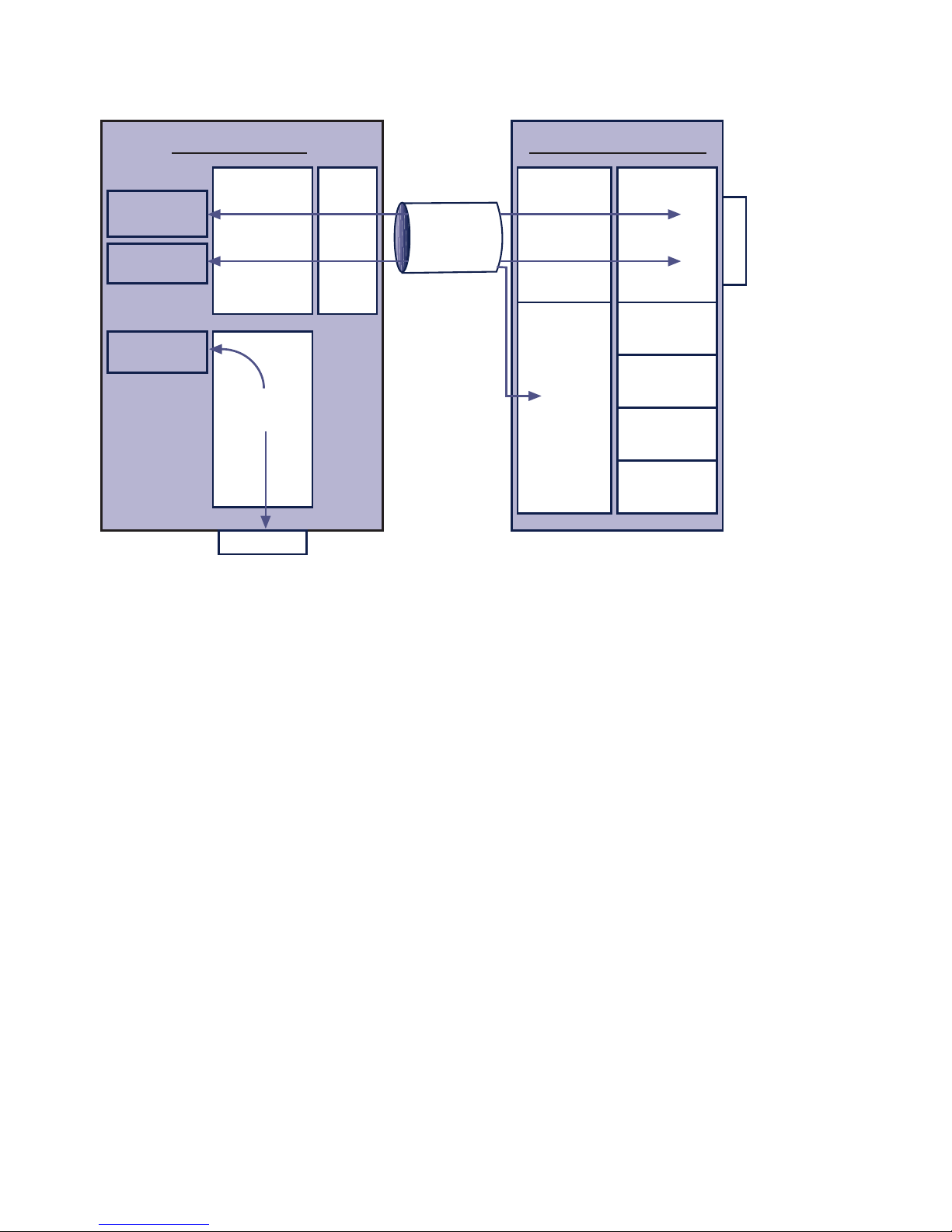
2.1.3 System overview
On the hardware side the W&T USB-Server adapts the USB
devices. Processing of the time-critical USB protocol takes place
locally and is mirrored - time-decoupled - on the network side
to a TCP server service.
On the software side the W&T USB Port Redirector acts as a
virtual USB host controller. When the user connects to one of
the USB devices, the latter is available to the respective system
after opening the network connection as if it were locally
connected. Connections to USB devices are always exclusive,
i.e. a simultaneous attempt from a competing USB Port
Redirector is rejected and can only take place after closing the
first connection.
In order to keep the configuration effort of the firewall in
protected environments to a minimum, the entire network
communication takes place or a single, configurable TCP port.
In parallel with this there are management services for
configuration, firmware updates etc. available which, however,
are not required for the connection between USB-Server and
USB Port Redirector.
A list of all ports used by the USB-Server can be found in the
Appendix.
Page 18
18
W&T System Overview
USB1
USB2
W&T USB-Server
TCP/IP-Stack
Application
ports
Service
ports
Web based
management
Firmware
update
Inventory
Reset
USB devices
Windows-PC
TCP/IP-
Stack
Virtual
USB
host controller
Device driver
USB1
Device driver
USB2
W&T USBredirector
Standard
USB
host controller
USB devices
Device driver
Network
USB Host
controller
Page 19

19
W&T
Subject to errors and modifications
3 Assigning/Changing IP Parameters
After the hardware installation of the USB-Server, the IP address and any
subnet mask and gateway for operation in a TCP/IP network must be
assigned. Please check with your systems administrator for the correct
values of these parameters. The USB-Server factory default IP address is
190.107.233.110.
. Setting the IP address, subnet mask and gateway address using the
management tool WuTility
. Setting the IP address, subnet mask and gateway address using DHCP
protocol
. Changing the IP parameters using Web-Based-Management
Page 20

20
W&T Assigning/Changing IP Parameters
3.1 Managing the network parameters in the USB-Server
The W&T USB-Server distinguishes between two modes with
respect to its network-side basic parameters..
Static
IP address, subnet mask and gateway are stgored in the nonvolatile setup of the USB-Server, and DHCP protocol is disabled.
The parameters set using this method remain stored even after
power interruptions and resets until they are changed using
WuTility or Web-Based-Management.
DHCP (factory default setting)
DHCP protocol is enabled and the USB-Server attempts to
obtain its IP parameters from a DHCP server located in the
network. If no DHCP server can be accessed or the attempt to
obtain an IP address is rejected, the USB server operates using
the factory default IP address 190.107.233.110. When
switching from Static to DHCP mode using WuTility or WebBased-Management, the USB-Server reverts to this default IP
address until valid new parameters are assigned.
Page 21

21
Subject to errors and modifications
W&T Assigning/Changing IP Parameters
3.2 DHCP mode (factory default setting)
Many networks use DHCP (Dynamic Host Configuration
Protocol) for centralized and dynamic assignining of the
network parameters. As shipped and after a reset to the factory
default settings, DHCP mode is enabled, so that in network
environments with dynamic IP assigning all you need to do is
connect the device to the network. The following parameters
can be assigned using DHCP:
• IP address
• Subnet mask
• Gateway address
• Lease time
1
After an unintended address assignment or address
change to an unknown address using DHCP protocol, the
management tool WuTility can be used to find the USB server
and uniquely identify it based on its MAC address. Changing the
wrong IP address or switching to Static mode while disabling
DHCP protocol can also be done using WuTility.
3.2.1 Activating DHCP mode
DHCP protocol is activated by switching from Static mode to
DHCP mode using WuTility or Web-Based Management of the
USB-Server. The previous static IP address is then deleted and
DHCP protocol is enabled. The USB-Server returns to its default
address 190.107.233.110 until new network parameters are
assigned using a DHCP server.
• Activating using the management tool WuTility
In the device list select the desired USB-Server and click on
the IP Address button. In the following dialog window check
i
An explanation of the
gasic terms and
fundamentals of
addressing in the
Internet as well as
DHCP and BOOTP can
be found in our
manual „TCP/IPEthernet and Web-IO““.
Page 22

22
W&T Assigning/Changing IP Parameters
the radio button DHCP and then click on the Continue
button.
• Activating using Web Based Management
In the menu Config r Device r Basic Settings r Network
select the option Static. After entering the new IP address
and the valid subnet mask and gateway address, click on
the Apply button. To save the new setting in the USB-Server, select Logout and Save. The device can now be reached
under the new IP address.
1
Switching from Static to DHCP mode causes the
device to revert from the static set IP address to the
factory default setting 190.107.233.110. If the IP
assignment using DHCP fails, for example because no DHCP
server is available, the USB-Server may no longer be
reachable, especially in routed network environments.
Reactivating Static mode using WuTIlity can only be done
using a computer in the same physical network.
3.2.2 Deactivating DHCP mode
DHCP mode is deactivated by switching from DHCP mode to
Static mode using WuTility or Web-Based-Management on the
USB-Server. In both cases the new values for IP address, subnet
mask and gateway address must be manually specified.
• Deactivating using the WuTility management tool
From the device list select the desired USB-Server and click
on the IP Address button. In the resulting dialog window
activate the Static radio button. After entering the new IP
address and the valid subnet mask and gateway address
click on the Continue button..
• Activating using Web Based Management
In the menu Config r Device r Basic Settings r Network
activate the Static option. After entering the new IP address
as well as the valid subnet mask and gateway address click
i
Each IP address must
be unique within the
network.
Page 23

23
Subject to errors and modifications
W&T Assigning/Changing IP Parameters
on the Apply button. Clicking on Logout and Save saves the
new setting in the USB-Server and the device can again be
accessed under the new IP address.
3.2.3 System Name
To support a possible later automated updating of the DNS
system using the DHCP server, the USB-Server identifies itself
within the DHCP protocol by its system name. The factory
default name is USBSERVER- followed by the last three places of
the Ethernet address. For example the factory set system name
of a USB-Server having Ethernet address 00:c0:3d:01:02:03 is
USBSERVER-010203. The system name of the USB-Server can be
changed using Web Based Management.
3.2.4 Lease time
The lease time determined and sent by the DHCP server
specifies the time limit of the assigned IP address. After half
the lease time has expired the USB-Server attempts to extend
the time and update the address. If this is not possible by the
time the lease time expires, for example because the DHCP
server can no longer be reached, the USB-Server deletes the IP
address and reverts to the factory default address
190.107.233.110. At the same time the cyclical search for
alternate DHCP servers for assigning a new IP address is started.
Because the clock is absent the lease time for the current IP
address is no longer available after a reset. After the restart
there is then a corresponding update request with the original
DHCP server. If the latter cannot be reached at this point in
time, the USB-Server deletes the IP address and reverts to the
factory default address 190.107.233.110. At the same time the
cyclical search for alternate DHCP servers for assigning a new
IP address is started.
Page 24

24
W&T Assigning/Changing IP Parameters
In DHCP mode the remaining lease time in seconds together
with the current IP address is displayed on the Web page Doc r
Properties.
1
If after the assigned lease time has expired the DHCP
server cannot be reached, the USB-Server deletes the IP
address and reverts to the factory default address
190.107.233.110 and starts the cyclical search for alternate
DHCP servers. All existing connections to W&T USB Port
Redirectors are closed. To prevent problems of this kind we
recommend configuring the lease time in the DHCP server to in-
finite whenever possible.
3.2.5 Reserved IP addresses
The USB-Server is designed as a TCP server and therefore
provides services which can be used as needed by computerside USB Port Redirectors. In order to open a connection these
need of course the current IP address of the USB-Server, so that
it makes sense to reserve a particular IP address for the USBServer on the DHCP server. This is generally done by linking the
IP address to be assigned to the unique Ethernet address of
the USB-Server, which can be found on the sticker on the
housing.
53641 [Model]
EN=00c03d004a05
OK xxxxxx
Ethernet address
3.2.6 Dynamic IP addresses
Fully dynamic address assignment, where the USB-Server gets
another IP address after each restart or after expiration of the
lese time, only makes sense in network environments with
automatic cross-connection between the DHCP and DNS
Page 25

25
Subject to errors and modifications
W&T Assigning/Changing IP Parameters
services. This means when a new IP address is assigned to the
UBS-Server, the DHCP server then also automatically updates the
DNS system. The new address is then associated with the
respective domain name. For detailed information about your
network environment, consult with your system administrator
if in doubt.
Page 26

26
W&T Assigning/Changing IP Parameters
3.3 Static mode
In Static mode the USB-Server uses static network parameters
and DHCP protocol is disabled. There are two ways of assigning
the static values for IP address, subnet mask and gateway.
3.3.1 Assigning static IP parameters using WuTility
The Windows tool WuTility in version 3.70 and higher supports
inventorying and management of the network basic parameters
of W&T USB-Servers:
• IP address
• Subnet mask
• Gateway address
• Umschaltung Static/DHCP
To assign these parameters the PC and USB-Server must be
located in the same physical network, whereby the function is
independent of the current address settings of the USB-Server.
This means even if the current parameters of the USB-Server do
not match the settings of the PC, you can still always use
WuTility to make a change. Any system password set in the
USB-Server must however be known.
Installing WuTility
The quickest way to install WuTility is using the Install button
on the start screen of the product CD included with the
product.
Then start WuTility using
Start r Programs r W&T Software Toolkit r WuTility
Starting the assignment dialog
Be sure that both the USB-Server and the computer are
connected to the same physical network. After starting, WuTility
automatically searches the local network for connected W&T
network devices and creates an inventory list. This search
Page 27
27
Subject to errors and modifications
W&T Assigning/Changing IP Parameters
procedure can be repeated as often as desired by clicking on
the Scan button:
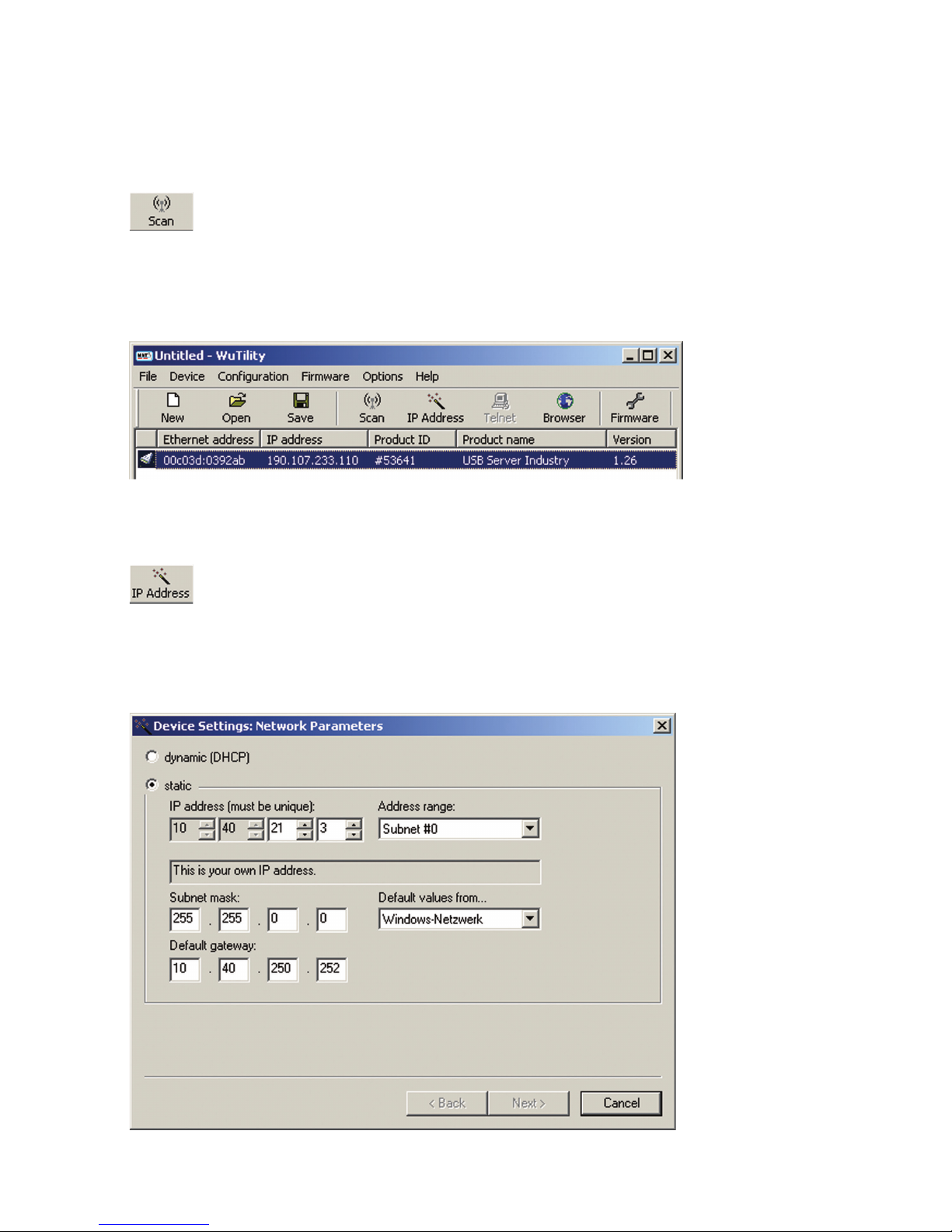
Within the inv entory list you can identify the desired USB-Server by its MAC address. For initial installations this IP address
is 190.107.233.110.
Select the desired USB-Server and then click on the IP address
button:
In the resulting dialog window activate the radio button Static
and enter the desired values for the IP address, the subnet mask
and the gateway address.
i
Each IP address must
be unique within the
network.
Page 28

28
W&T Assigning/Changing IP Parameters
After clicking on the Continue button you are also prompted
for the system password. Then the network parameters are
stored in the USB-Server in non-volatile memory.
All further settings are made using Web-Based-Management of
the USB-Server and an Internet browser. Select the desired USBServer from the WuTility inventory list and click on the Browser
button.
Additional information about management of the USB-Server
can be found in the section Web-Based-Management.
1
Changing the network parameters is protected by the
system password. To prevent unauthorized use, we
recommend assigning a system password for operating ComServers.
3.3.2 Assigning static IP parameters using WBM
As shipped and after a reset to the factory default settings the
USB-Server is in DHCP mode. As long as no address is assigned
using a DHCP server, the USB-Server can also be reached in parallel through its default IP address 190.107.233.110. Switching
to Static mode and assigning the new IP parameters can also
be done using Web-Based-Management and a browser.
1
In contrast to address assigning using WuTility, initial
startup of multiple USB-Servers using the methods
described in the following can be done only in sequence. Only
after a USB-Server has received its new IP address can the next
USB-Server be connected to the network.
Page 29

29
Subject to errors and modifications
W&T Assigning/Changing IP Parameters
1
Notify the responsible network administrator before
makingany changes to the network settings of a
computer.
On the computer side one of the two following conditions must
be met:
• The IP address of the computer used is in the subnet range
190.107.0.0 or is temporarily changed to an appropriate
value. You need administrator rights to change the IP
address of a computer. Notify your responsible network
administrator before making changes to the network
settings of a computer.
• A fixed route which directs the IP address 190.107.233.110
to the local network is setr up on the computer. Administrator rights are required in order to set up such a route. The
command line syntax for creating a fixed route under
Windows XP is:
route ADD 190.107.233.110 MASK 255.255.255.255 [IP address of the PC]
Finally, start the Internet browser and enter the destination
http:// 190.107.233.110 in the address line and change the
network settings to the new values on the Web pages of the
USB-Server.
Page 30

30
W&T Assigning/Changing IP Parameters
Page 31

31
W&T
Subject to errors and modifications
4 Hardware - Interfaces and Indicators
. Supply voltage via PoE and external
. Ethernet port
. USB ports
. LED indicators
Page 32

32
W&T Ports and indicators
4.1 Supply voltage
Power for the W&T USB-Server can be provided either via PoE or
from an external power supply.
4.1.1 PoE supply
The model 53641 USB-Server is suitable for use in PoE
environments according to IEEE802.3af. Here the supply voltage
is brought in by the network infrastructure through the RJ45
terminal. The USB-Server supports both phantom power using
data pairs 1/2 and 3/6 as well as power thorugh the unused
wire pairs 4/5 and 7/8.
In order to enable power management for the supplying
components, the USB-Server identifies itself as a Power Class 3
device (power consumption from 6.49W to 12.95W).
4.1.2 External supply
As an alternative to PoE, the USB-Server can also be powered
through the plug-in screw terminal located on the underneath
of the housing. The DC voltage used must lie in the following
range:
• DC voltage: 24V (-10%) - 48V (+10%)
The input of the USB-Server is equipped with a bridge rectifier,
so that the polarity of the supply voltage is non-critical.
The current draw can be found in the technical appendix.
Page 33
33
Subject to errors and modifications
W&T Ports and indicators
4.2 Ethernet port
The USB-Server Industry has an IEEE 802.3 compatible network
terminal. The physical connection is made using TP copper
cable.
4.2.1 10/100BaseT to RJ45
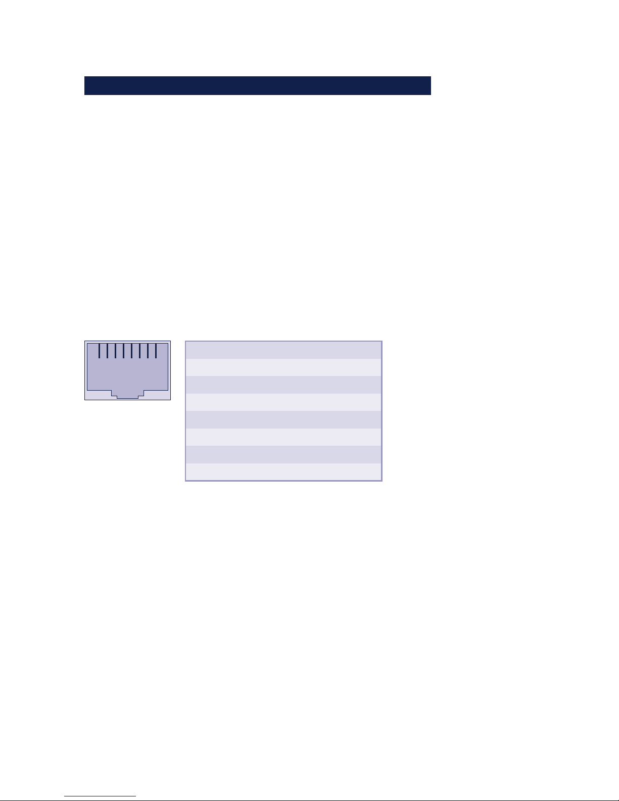
The 10/100BaseT network interface has a shielded RJ45
connector. The assignments indicated in the following
illustration correspond to an MDI interface, so that the
connection to the hub or switch is made using a max. 100m
long, 1:1 wired and shielded patch cable.
1 2 3 4 5 6 7 8
Pin
1
2
3
4
5
6
7
8
Direction
Out
Out
In
In
IN
In
In
In
Device
w/o PoE
Tx+
Tx-
Rx+
nc
nc
Rx-
nc
nc
Device
with PoE
Tx+
Tx-
Rx+
Vcc positive
Vcc positive
Rx-
Vcc negative
Vcc negative
The network connection is galvanically isolated from the supply
voltage and the USB ports to at least 500V
rms
.
Power-over-Ethernet - PoE
The USB-Server can obtain its power through the network
interface according to IEEE802.3af/Power-over-Ethernet. Power
can be brought in using the data pairs or the wire pairs unused
with 10/100BaseT (see also the Supply Voltage section).
Page 34

34
W&T Ports and indicators
Auto Negotiation: 10/100BaseT, Full/Half Duplex
In its factory default setting the W&T USB-Server uses AutoNegotiation mode. To prevent communication problems caused
for example by a duplex mismatch, we recommend also
operating the used port on the switch or hub in Auto-
Negotiation mode. Here both the transmission speed and the
duplex procedure are automatically negotiated and
correspondingly set in the devices.
1
Managable switches often use special protocols
(Spanning Tree Protocol, Port-Trunking, ...), as needed
for example for uplinks to other switches or the wideband
connection of servers. These protocols are generally not needed
for connecting normal terminal devices such as the USB-Server,
but they may slow down opening of communication
considerably after a restart. We recommend disabling these
protocols and functions on the port used for the USB-Server.
Please consult with your system administrator in this regard.
Page 35
35
Subject to errors and modifications
W&T Ports and indicators
4.3 USB ports
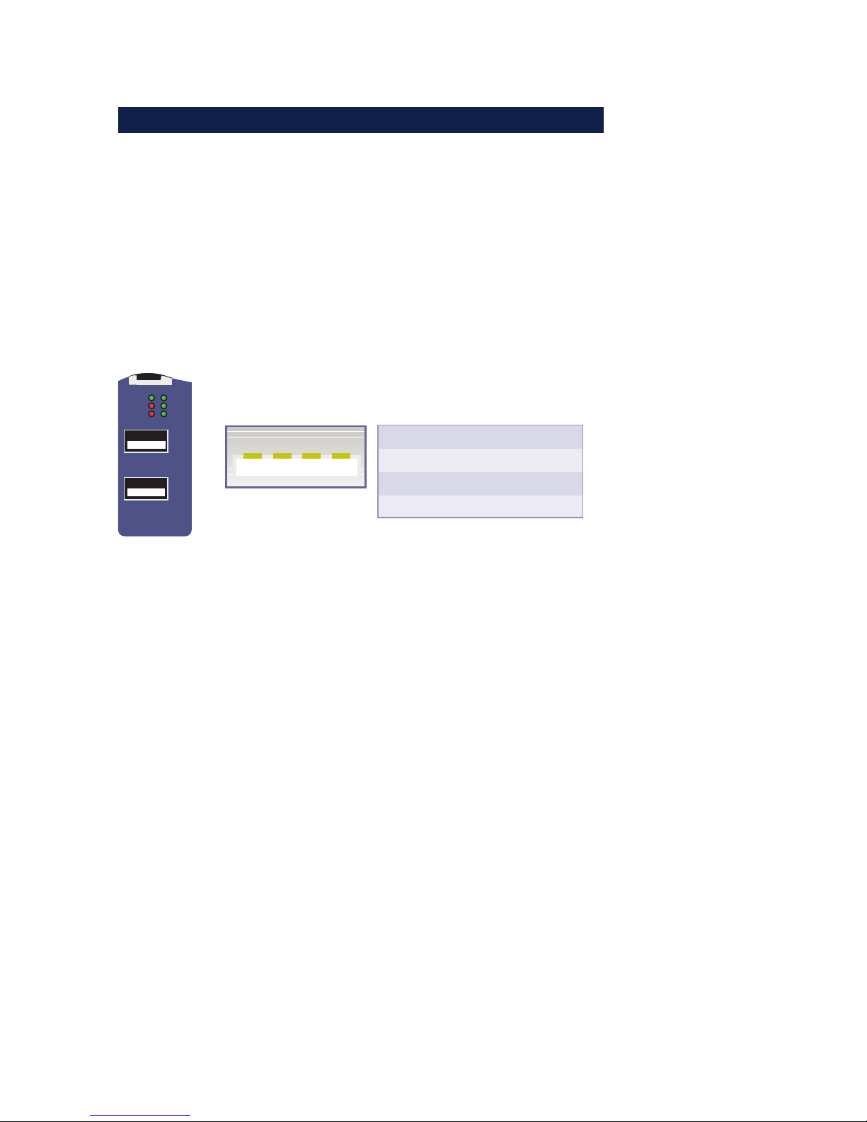
The USB standard specifies both the wiring of the port and the
names of the signal lines. The configuration shown below
corresponds to a USB standard port. Both USB ports are able to
provide devices with 5V and a maximum of 500mA each,
independently of each other. To prevent hardware damage the
respective USB port is automatically disconnected when there
is an overload and this is indicated by the associated LED
turning on.
Error
USB 1
USB 2
USB 2
USB 1
Connect
USB 2
USB 1
PowerStatus
4213
USB Port
Pin
1
2
3
4
Name
VCC
D-
D+
GND
Description
+5 V
Data -
Data +
Ground
Both ports of the W&T USB-Server conform with USB 1.0, 1.1
and 2.0 with transmission speeds of 1.5 Mbit/s (Low), 12 Mbit/
s (Full) and 480 Mbit/s (High). This means most USB devices
using the transfer modes Control, Interrupt and Bulk are
supported. Isochronal mode, which is used mainly in audio and
video applications, is in development.
1
In accordance with the USB standard, connecting and
unplugging USB devices is always possible and
permissible from a purely electrical point of view (hotplugging). To prevent data loss - for example when using
memory sticks - we recommend disconnecting devices only
when there is no connection between a network computer and
the USB device and the associated Status LED is off.
Page 36
36
W&T Ports and indicators
4.4 LED indicators
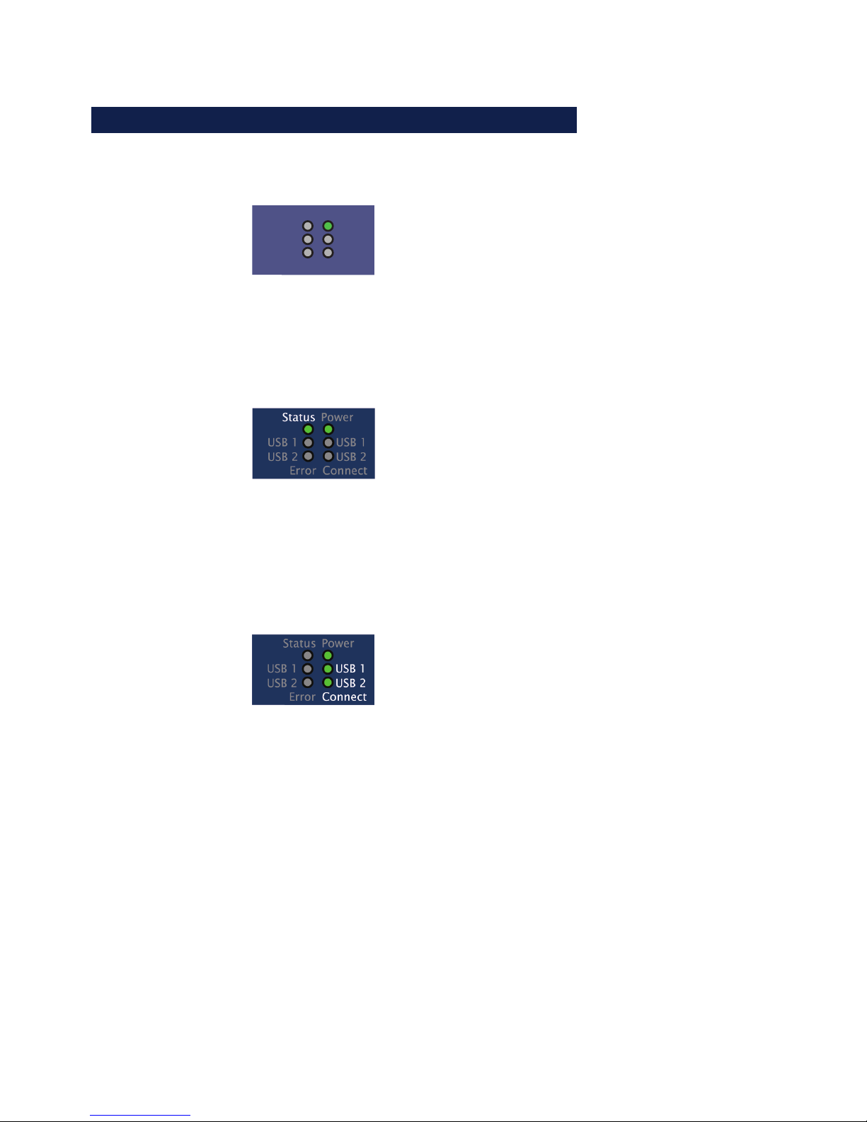
The USB-Server has six LEDs on the front panel.
Power
Error
USB 2
USB 1
Connect
USB 2
USB 1
PowerStatus
OFF: No power is present. Check for proper connection of
the supply voltage on PoE or from the external power
supply.
ON: There is power from PoE or the external power supply.
Status
OFF: There is no link to a switch or hub. Check the cabling
to the switch/hum and whether it us turned on or not.
ON: There is a link to a switch or hub.
Flashing: Indicates network-side data traffic between the
USB-Server and a network component.
Connect USB1|2
OFF: There is no connection to a W&T USB Port Redirector in
the network..
ON: There is an active connection between the USB device
connected to an associated port and the W&T USB Port
Redirector. The USB device is incorporated into a system
and unplugging it may result in data loss.
Page 37

37
Subject to errors and modifications
W&T Ports and indicators
Error USB1|2
ON: The corresponding port was automatically disabled due
to an overload. The connected USB device requires a current
of > 500mA or is defective.
Special case - firmware update
If the USB-Server was initialized by the WuTility management
tool for a firmware update, the four LEDs USB-Connect USB1/2
and USB-Error1/2 flash cyclically approx. once a second. Active
sending of firmware files is indicated in addition by flashing of
the Status LED.
Special case - reset to factory default settings
When there is a hardware reset to the factory default settings
using the internal jumper, cyclical flashing of the four LEDs USB-
Connect USB1/2 and USB-Error1/2 indicates that the factory
settings were successfully initialized. The jumper can then be
removed and the USB-Server is ready again after a power-down
reset (see Appendix, Reset to factory default settings section).
Page 38

38
W&T Ports and indicators
Page 39

39
W&T
Subject to errors and modifications
5 The W&T USB Port Redirector
The W&T USB Port Redirector consists on one hand of the virtual host
controller designed as a Windows core driver. In addition to controlling the
network connection to the USB-Server, it takes care of system-side
processing of the USB handling. The associated configuration tool
inventories the available USB-Servers and allows the connected USB devices
to be logged on and off with a mouse click.
. System requirements
. Installation/Deinstallation
. Using the configuration tool
. Configuring the W&T USB Port Redirector
Page 40
40
W&T The W&T USB Port Redirector
5.1 Overview
The W&T USB Port Redirector, which is implemented as a
Windows core driver, provides a virtual USB host controller
which behaves with respect to the Windows system like a local
standard controller.
Configuration of the core driver is registry-based using the
configuration tool which is started using the link Configure USB
Port Redirector. In addition, the configuration tool automatically
searches the local subnet for W&T USB-Servers and enters them
in a list with any connected USB devices.
1
Additional and possibly more recent information about
the individual configuration options can be found in the
online help for the W&T USB Port Redirector.
5.1.1 Port numbers
To communicate with the USB devices the W&T USB Port
Redirector uses the UsbServerPort configured in the USB-Ser-
ver. The factory set name is TCP/32032.
Any installed security components (software or hardware
firewall, security suites etc.) must allow communication over this
port number without delay. This is now however absolutely
necessary for the UDP port 8513 used for automatic
inventorying. Inserting the USB-Servers can be done in this case
Page 41

41
Subject to errors and modifications
W&T The W&T USB Port Redirector
manually (for additional information see section The inventory
list).5.2 Installation/Deinstallation of the W&T USB Port
Redirector
Page 42

42
W&T The W&T USB Port Redirector
5.2 Installation/Deinstallation of the USB Redirector
Installation of the W&T USB Port Redirector can be done directly
from the product CD included in the scope of delivery.
Alternatively the current version and updates are always
available on the W&T Web site at http://www.wut.de.
On the system side the following requirements must be met:
• Operating system Windows XP/Vista/Windows7 incl. 64-bit
and server editions
• Login as Administrator or Administrator rights
1
In order to be able to publish W&T USB Port Redirector
updates in as timely a fashion as possible, the driver is
not WHQL certified. To successfully finish the installation the
corresponding message for the Windows logo test must be
acknowledged with Continue installation.
In addition to the core driver of the W&T USB Port Redirector
the associated configuration tool is installed, which is located
in the Windows Start menu in the new program group W&T USB
Port Redirector.
1
Installation of the W&T USB Port Redirector is done as an
update to any already present older versions. All the
settings and connection parameters made remain intact and
are then available unchanged.
5.2.1 Installation from the product CD
After starting the product CD included in the scope of delivery,
first select the desired language Deutsch or English and then
go to the USB-Server tab. After clicking on the Search button
select the 32- or 64-bit version of the driver as appropriate for
your system in the resulting dialog box and click on the Install/
Uninstall button.
Page 43
43
Subject to errors and modifications
W&T The W&T USB Port Redirector
5.2.2 Installation from download
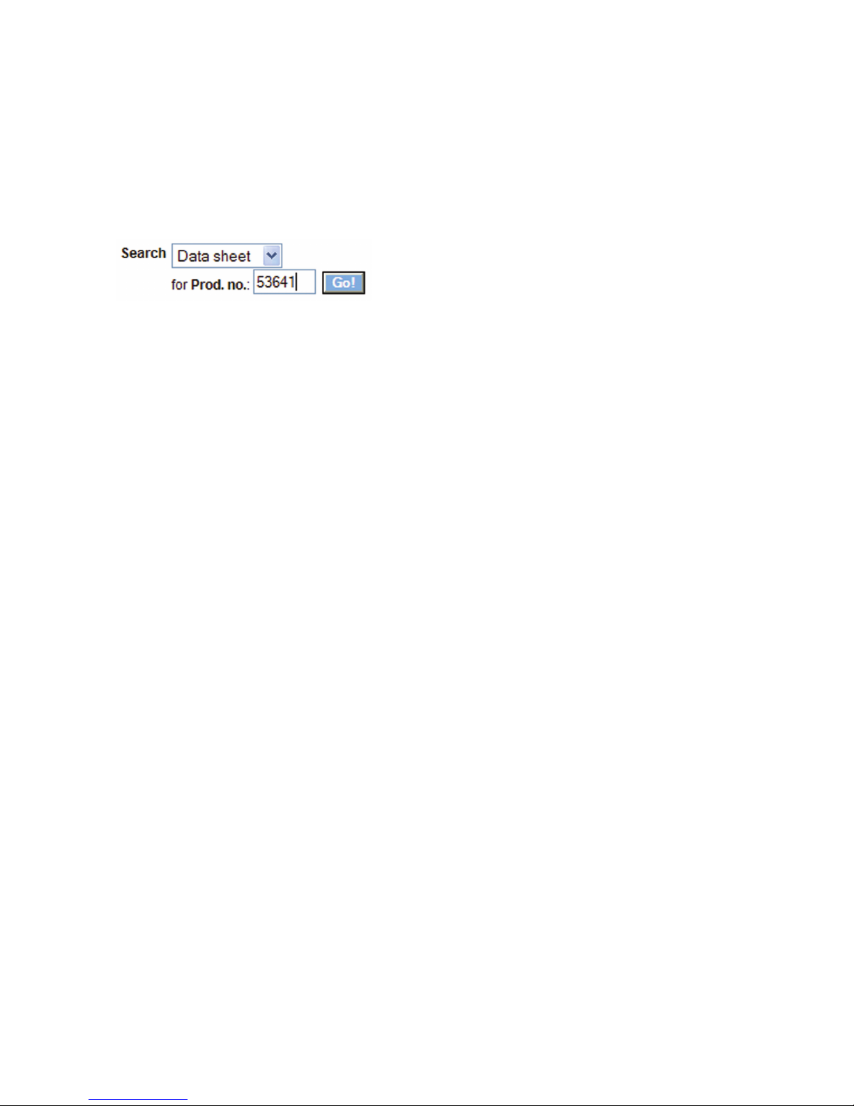
From the homepage http://www.wut.de the simplest methodd
is to enter article number 53641 in the Search function. Set the
drop-down box to Drivers and then click on the Go button.
The following page contains a direct link to the current version.
After downloading and unzipping the archive, start the
installation by starting the MSI file.
5.2.3 Uninstalling
For uninstalling, the program group W&T USB Port Redirector
has its own Uninstall entry. Alternatively you can uninstall using
the Windows software management function in the Control Panel.
Page 44
44
W&T The W&T USB Port Redirector
5.3 The inventory list
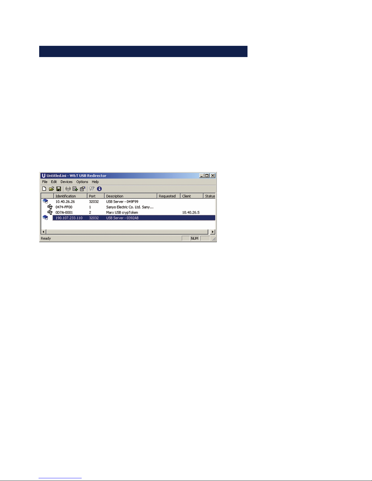
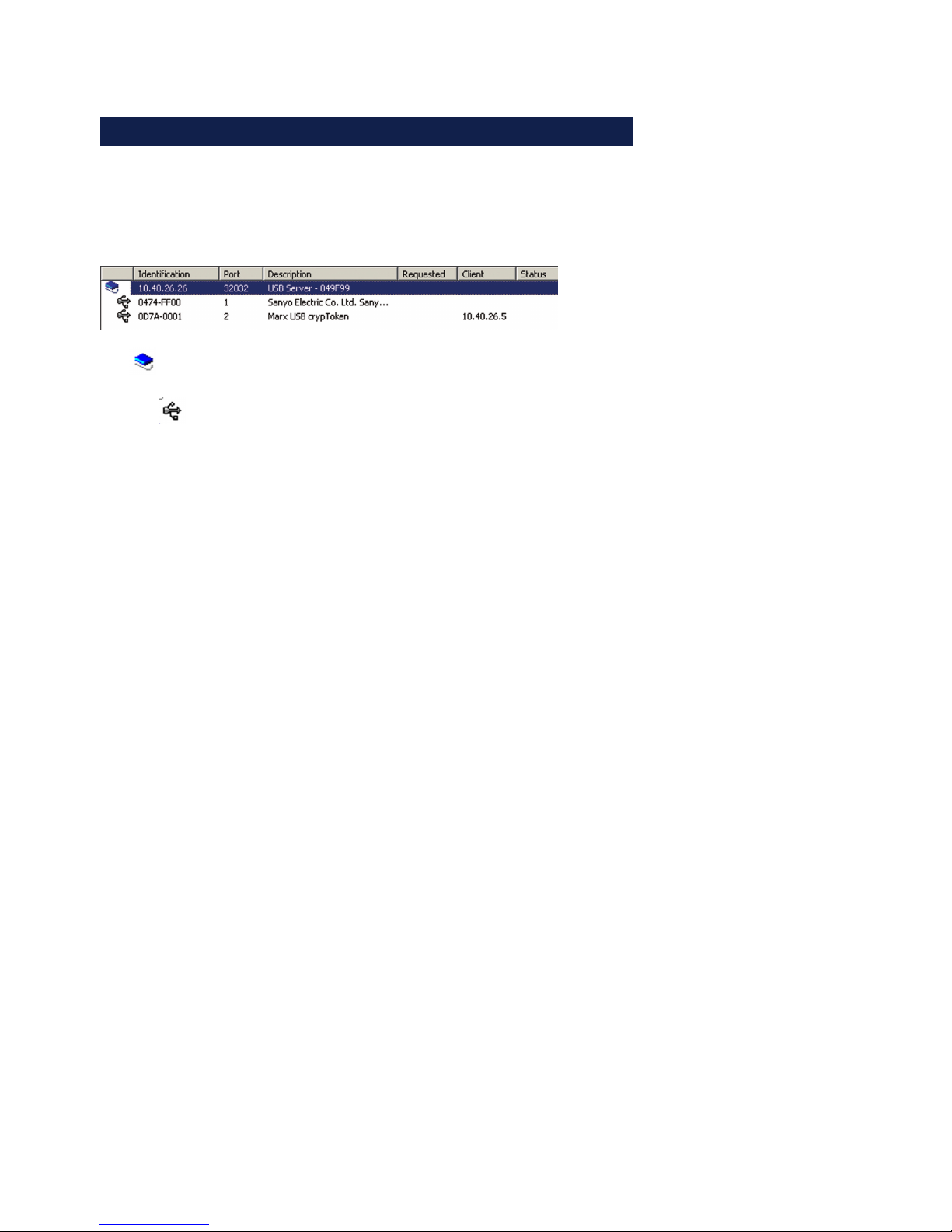
The inventory lists in the configuration tool represent the
required and available W&T USB-Servers with the connected USB
devices along with additional information in a tree structure.
•
Icon for USB-Server
•
Icon for a USB device. This is connected to the first USBServer shown above.
• Identification
For USB-Servers you enter here the IP address. For USB
devices the vendor and product ID are shown.
• Port
For USB-Servers the TCP port used for USB data exchange is
shown (factory setting = 32032). For USB devices which of
the two physical USB ports on the USB-Server the device is
connected to is shown.
• Description
For USB-Servers the system name is indicated here. This is
configurble using Web Based Management and is factory set
to usbserver- followed by the last three places of the MAC
address (e.g.. usbserver-040506). For USB devices the
description read out via USB is shown..
• Requested
Indication whether and, if appropriate, how long USB devices
are connected on the resepctive computer.
• Client
IP address of the computer on which the USB device is
connected. To open a coinnection to this USB device this
column must be blank.
• Status
Error and status messages for the respective USB device..
Page 45

45
Subject to errors and modifications
W&T The W&T USB Port Redirector
5.3.1 Automatic inventory list creation
Here the local subnet automatically searches for W&T USBServerns and USB devices connected to them. The inventorizing
is done in two phases, whereby first the W&T USB-Servers are
found using a UDP broadcast (port 8513). Then any connected
USB devices are queried using a TCP connection to the
UsbServerPort (factory setting 32032). If the UsbServerPort is
reconfigured via Web Based Management in the USB-Server, the
specification TCP-Port must be changed accordingly in the
Properties dialog box.
The search is carried out automatically each time the
configuration tool is started and when creating a new list using
the File r New function.
A manual search can be performed at any time by clicking the
Scan
button.
1
Automatic inventorizing is done using UDP port 8513
and the TCP UsbServerPort configured in the USB-Server
(factory setting = 32032). Any firewall or security software
installed in the respective computer must permit this
communication.
5.3.2 Manual entries in the configuration list
Remote USB-Servers connected through routers or gateways
cannot be detected by the automatic scan function of the
configuration tool. The entry in the inventory list must in such
cases be made manually.
Page 46
46
W&T The W&T USB Port Redirector
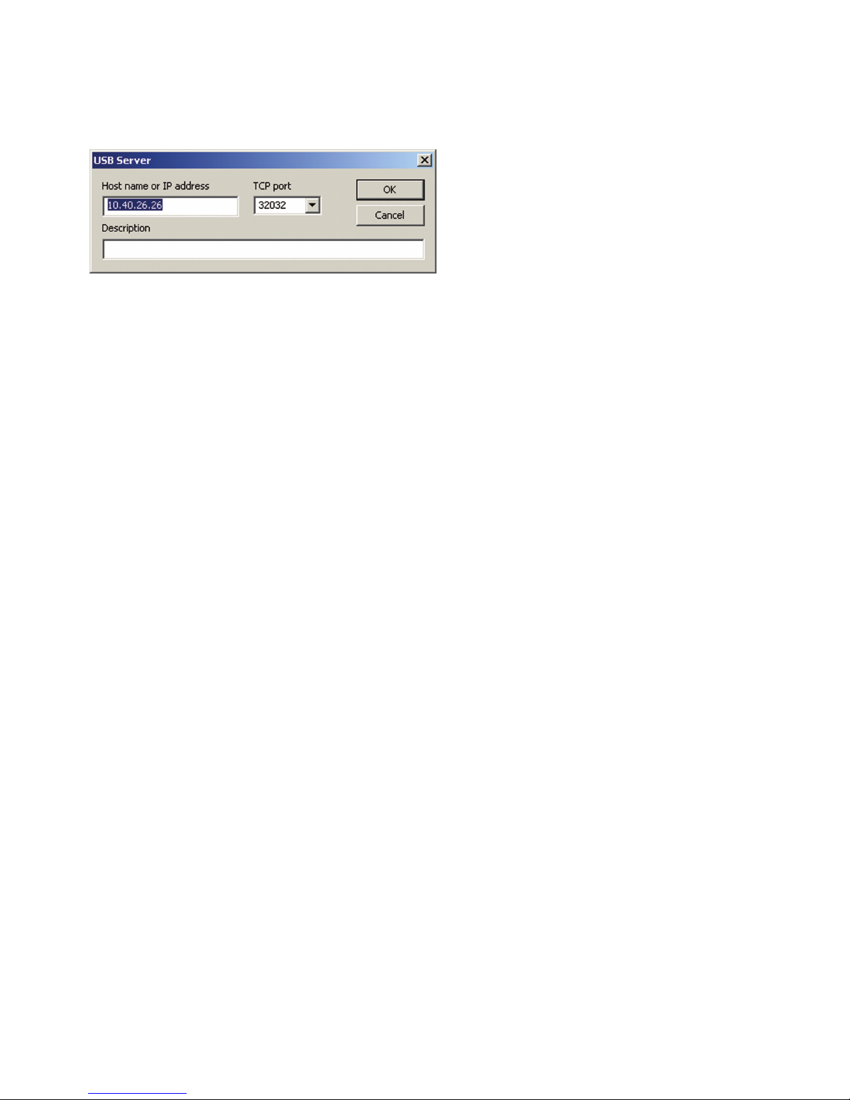
The menu path Devices r Add opens the following dialog:
Enter here the IP address or the host name of the desired USBServer. The local TCP port on the USB-Server used for further
communication is factory set to 32032. If the UsbServerPort is
reconfigured via Web Based Management in the USB-Server, the
specification TCP-Port must be changed accordingly in the
Properties dialog box.
Clicking on OK adds the USB-Server to the inventory list and
the configuration tool attempts to use the specified TCP port
to locate the connected USB devices.
5.3.3 Saving and opening inventory lists
Especially in routed environments with manually added USB-Servers you should save created inventory lists.
The configuration tool always opens automatically at startup
and checks the availability of the USB-Servers and USB devices.
In addiiton, the local network is always searched for new
devices.
Saved but no longer accessible devices remain in the list but
are shown as grayed out.
Page 47

47
Subject to errors and modifications
W&T The W&T USB Port Redirector
5.4 Using USB devices - Plug/Unplug
To enable a USB device connected on the USB-Server in the
Windows plug and play system, it must be included using the
configuration tool. Compared with a local computer, this
corresponds to plugging the device into a USB port. Windows
then installs any existing standard drivers (e.g. many memory
sticks), keyboards, etc.) or starts the search for device-specific
drivers.
5.4.1 System response / conflict protection
A USB device can be used by only one PC at any given time.
Only after the latter has closed the connection can the device
be used by a different computer. The information as to whether
a USB device is already in use can be found in the Users column
in the inventory list.
The procedure described below for including a USB device is
irrespective of any conflict. If the desired USB device is in use,
the USB Port Redirector cyclically attempts to open a
connection.
1
Conflict protection refers to the respective USB port to
which the device is connected. This means a
simultaneous access from two PCs to different USB ports is of
course not a problem.
5.4.2 Adding a USB device - Plug
Select the desired USB device in the inventory list of the
configuration tool and right-click on it. You can also doubleclick on the desired device.
Page 48
48
W&T The W&T USB Port Redirector
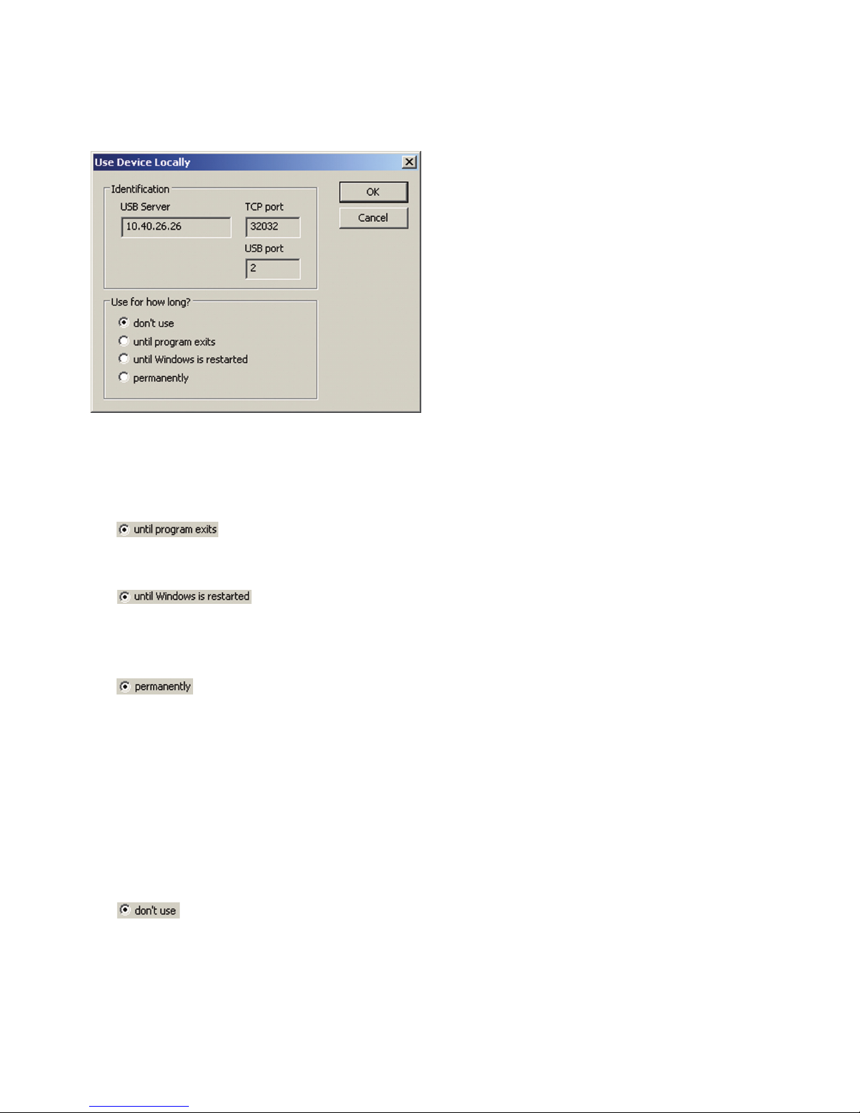
The Properties menu opens the following dialog box:
While adding you have three options. Clicking on the OK button
after selecting the desired option opens the connection to the
USB device and triggers the plug event in the Windows system.
•
The device remains connected until the configuration tool
is closed.
•
The device remains linked in the system until Windows is
closed. The Start/Stop configuration tool can be closed
without affecting the connection to the device.
•
The USB device is linked permanently. When the computer
is restarted an attempt is automatically made to link the
device again.
5.4.3 Closing a connection - Unplug
Just as for linking a USB device, suspending it is done using
the Properties dialog box.
•
Clicking on the OK button after selecting closes the
connection to the USB device and triggers the Unplug event
in the Windows system.
Page 49

49
W&T
Subject to errors and modifications
6 Web-Based-Management
The W&T USB-Server configuration is Web-based and can be opened using
any Web browser. WBM (Web-Based Management) is session-oriented. This
means all changes made are first temporarily buffer stored and not saved in
the non-volatile Setup of the USB-Server until a final save function has been
performed.
. Navigation within the WBM
. List of connected USB-Devices
. Network basic parameters
. Diagnostic functions
Page 50

50
W&T Web-Based-Management
6.1 Starting and navigating the WBM
To access the WBM of the USB-Server, start your Internet browser
and enter the IP address of the USB-Server and a port number if
appropriate.
http://[IP-Adresse]:[port number]
Ab Werk ist für das WBM der HTTP-Standard-Port 80 konfiguriert. In diesem Fall kann die Angabe der Portnummer in der
Adresszeile entfallen.
The factory default setting is for HTTP standard Port 80. In this
case you do not need to enter the port number in the address
line.
6.1.1 Navigation concept of the USB-Server
The WBM of the USB-Server is session-oriented using a
password-protectedlogin. Without a login the start page simply
shows basic information but does not permit any changes to
the settings.
After loggin in you can make any unber of settings during a
configuration session. Clicking on the Apply button on the
respective pages causes them to be temporarily stored by the
USB-Server. Once all the settings have been made, exit the
configuration session and use Logout and click on Save. Only
now are all changes sent to the non-volatile memory of the
USB-Server and activated..
You can exit a configuration session at any time without saving
your changes by clicking on the Cancel button.
1
To ensure errorless running of the configuration
sessionwe recommend that when within the WBM only
the nvaigation links provided by the USB-Server be used rather
than the Back and Forward function of the browser.
Page 51
51
Subject to errors and modifications
W&T Web-Based-Management
6.1.2 The Start page of the USB-Server
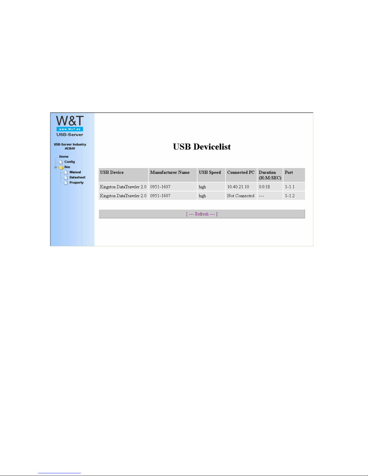
The basic struction of the Web pages in the USB-Server is
divided into the navigation tree on the left side and the main
frame with the contents of the respective menu branch on the
right side.
Without logging in you can view a list of the connected USB
devices with their associated information. In addition, the menu
branch Doc provides access to the quick user‘s guide, the data
sheet and the Properties page with device-specific information.
Page 52
52
W&T Web-Based-Management
6.2 WBM - configuration sessions
Setting on the W&T USB-Server are made within passwordprotected configuration sessions. These are exclusive, i.e. only
one session can be active at a time.
6.2.1 Login
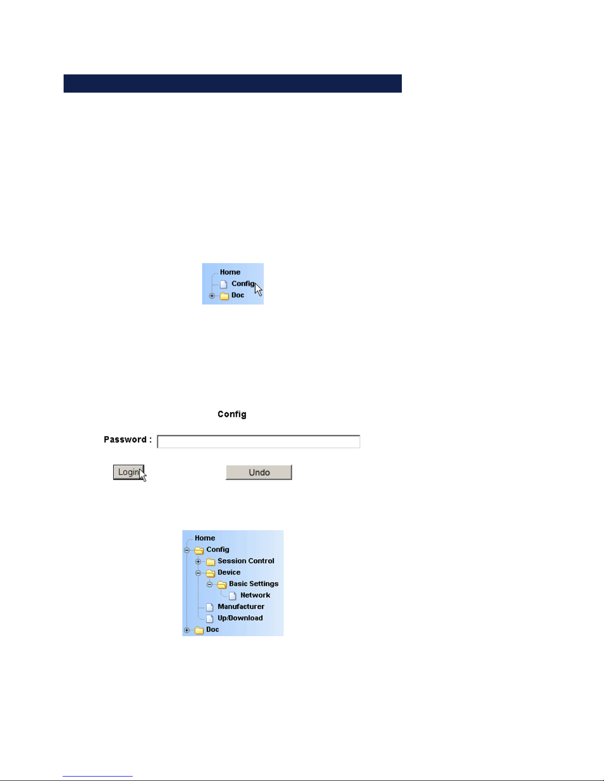
The Config link in the navigation tree takes you to the login
page of the USB-Server.
In its factory default setting the USB-Server does not require a
password. In this case the Password entry field remains blank,
and clicking on the Login button starts a configuration session.
If a password as assigned by the user, it must of course be
entered.
After successful login an expanded configuration tree appears.
Page 53
53
Subject to errors and modifications
W&T Web-Based-Management
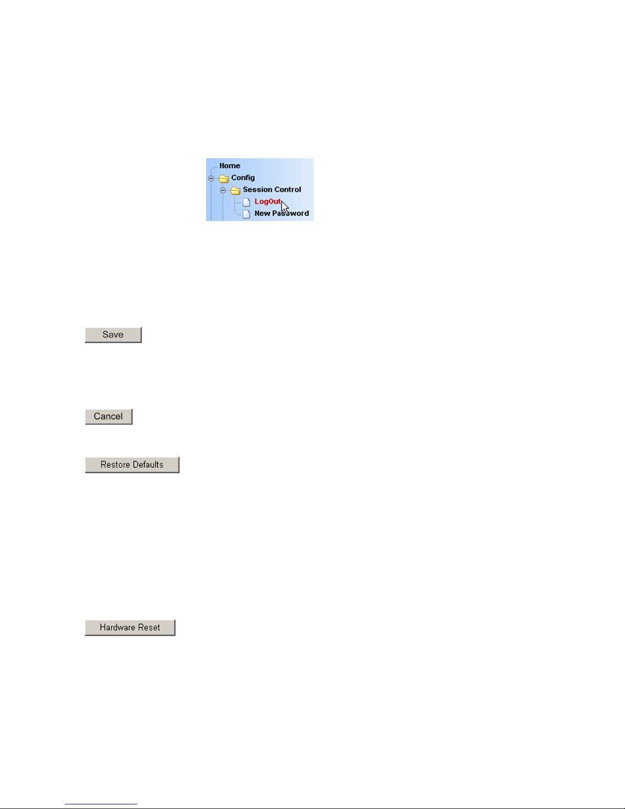
6.2.2 Logout
Quit a configuration session by using the Logout page of the
USB-Server.
1
All functions except for Cancel cause any connections
from PCs to connected USB devices to be closed. To
prevent data loss, we recommend any users listed on the
homepage of the USB-Server to be previously notified.
... closes the session and saves all changes made to the nonvolatile memory of the USB-Server. If the changes require
restarting the device, this is automatically performed.
... closes the session and cancels all changes.
... closes the session and reverts to the settings of the USBServer. All settings which are different from the default values
including the network parameters are lost.
1
In environments with static network parameters (no
DHCP)assigning the new IP address can be done only
from a workstation which is located in the same subnet as the
USB-Server.
...closes the session without saving any changes and restarts
the USB-Server.
Page 54
54
W&T Web-Based-Management
6.3 WBM - Assigning passwords
The password may be up to 32 characters and protects the
following configuration accesses to the W&T USB-Server.
• Web Based Management
• Uploading configurations
• Firmware update
• Reset Port
• Setting using WuTility
1
Deleting an unknown or forgotten password to the
can only be done by a hardware reset of the USB-Server
to its default settings.
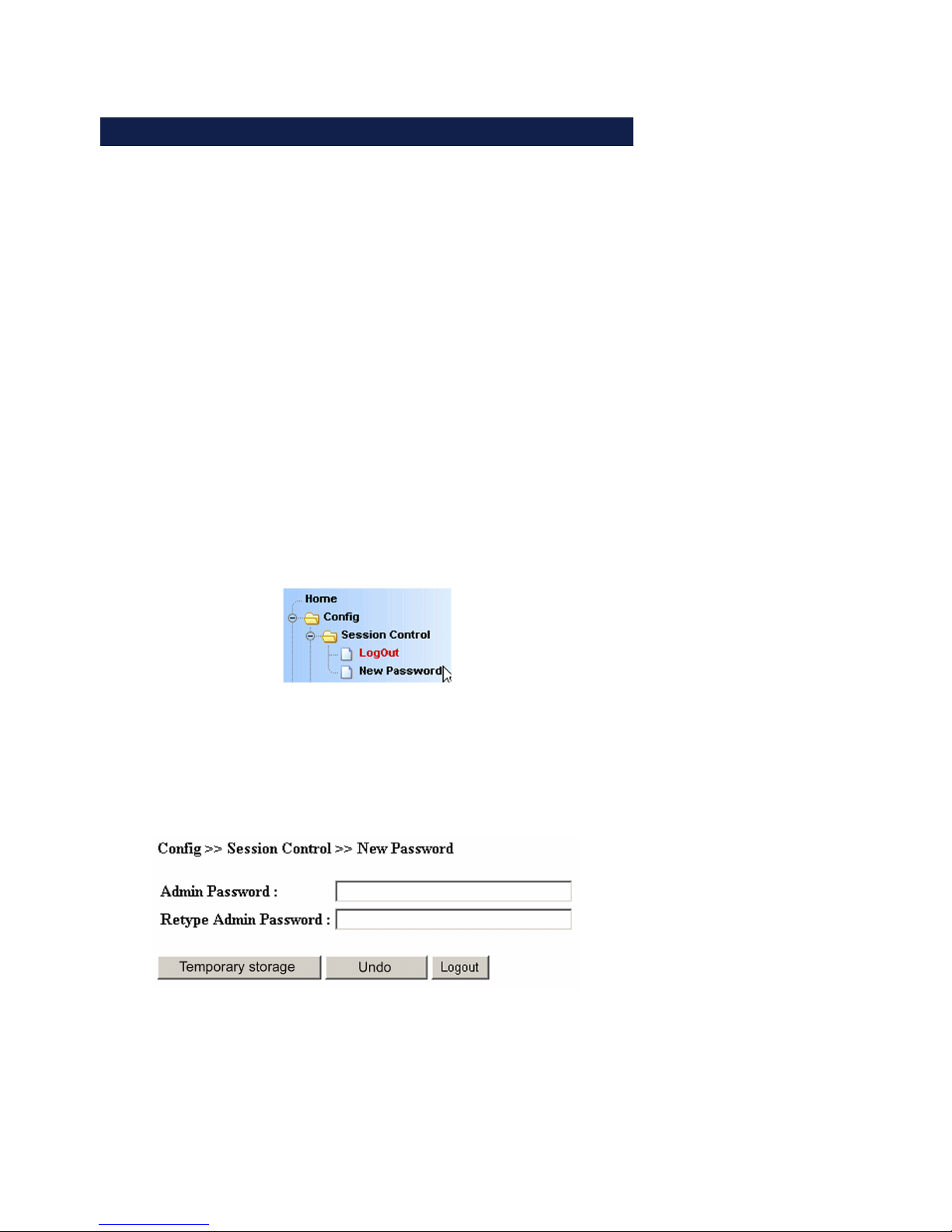
Config r Session Control r New password in the navigation tree
takes you to the Web page for assigning or changing the
password.
Enter the new password into both fields. To delete an existing
password, leave both fields blank. Clicking on the Apply or Log-
out button temporarily saves the change. Final saving to the
non-volatile memory is done from the Logout page and clicking
on the Save button.
Page 55
55
Subject to errors and modifications
W&T Web-Based-Management
6.4 WBM - Network basic parameters
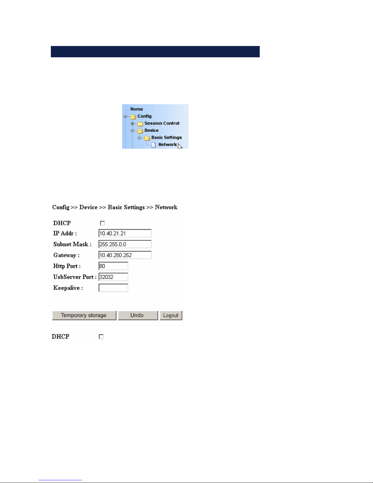
Config r Device r Basic Settings r Network in the navigation
tree takes you to the Web page with the network-side basic
parameters.
1
Saving changes made here closes any connections from
PCs to connected USB devices. To prevent data loss, we
recommend any users listed on the homepage of the USB-Server
to be previously notified.
In DHCP mode the USB-Server obtains the network-side basic
parameters IP address, subnet mask and gateway address from
a DHCP server located in a network. In Static mode these
parameters are determined statically using the following entry
fields. Detailed information about both modes can be found in
the sections DHCP Mode and Static Mode.
Page 56
56
W&T Web-Based-Management
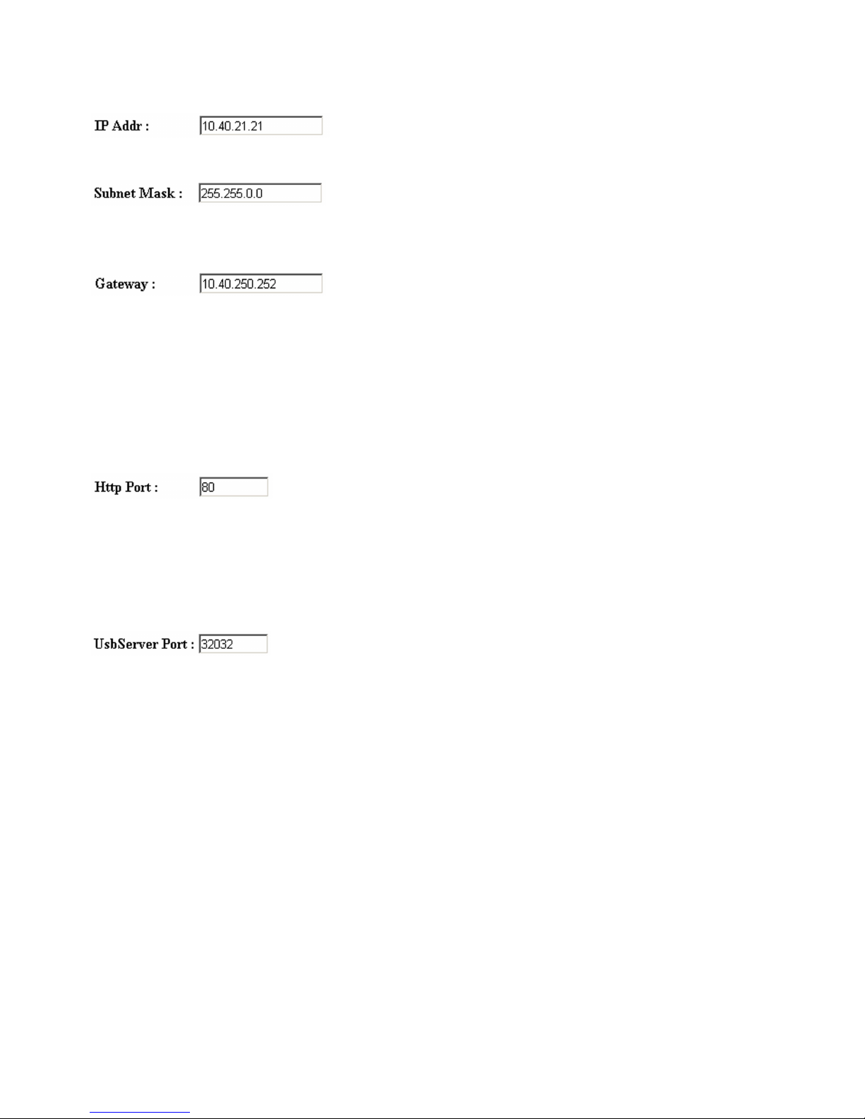
For entering the IP address when DHCP is disabled.
For entering the subnet mask for the respective network when
DHCP is disabled.
For entering the gateway for the respective network when DHCP
is disabled.
1
Valid values for IP address, subnet mask and gateway
canbe obtained from your network administrator. If you
assign the IP address yourself, be sure that there are no address
conflicts with other devices.
TCP port number (decimal) under which the Web-Based-Management of the USB-Server can be reached. The factory setting
is for HTTP standard port 80. When using other port numbers,
these must be separated by a colon with opening the WBM in
the address line of the browser (e.g. http://10.10.1.1:1234)
TCP port number (decimal) under which the W&T USB Port
Redirector communicates with the connected USB devices.
When using a different port number, it must be entered the
same in the Properties of the USB-Server in the configuration
tool (see Inventory List for additional information).
1
The TCP port used here must be permitted in any
firewallsbetween the USB-Server and the USB Port
Redirector. The USB Port Redirector acts here as a client and is
thereby the connection partner.
Page 57

57
Subject to errors and modifications
W&T Web-Based-Management
The Keep-Alive-Check, which is factory set to 5s, monitors all
TCP connections. If there is no data traffic within a TCP
connection for the specified time limit, the USB-Server generates
a Keep-Alive packet. If the connection partner does not respond
to this packet, the connection in the USB-Server is reset. The
affected USB device is then available again to other PCs.
Page 58

58
W&T Web-Based-Management
Page 59

59
W&T
Subject to errors and modifications
7 Appendix
. Up-/downloading configuration data
. Firmware update
. Reset to factory default settings
. Used ports and network security
. Technical data
Page 60

60
W&T Appendix
7.1 Up- and downloading configuration data
The USB-Server allows you to read out all its current
configuration data or write it back to the device. This allows
complicated setting profiles to be archived and sent back
complete to thedevices whenever needed. FOr group startups
all you need to do is configure a device using Web-Based-Management and then copy the profile you have created to the
other USB-Servers.
The USB-Server provides the configuration profiles in XML
format. This makes it possible to modify the data using a text
editor before uploading to another device.
7.1.1 Up- and downloading the configuration using WBM
In the Up-/Download menu branch use the Download button to
read and save the configuration of the USB-Server. Likewise the
Upload button can be used to send a saved configuration
profile to the USB-Server.
Downloading a configuration from the USB-Server does not
provide a pure XML file. Handling of this file format varies with
different browsers. If you want the file to be represented by the
browser formatted, the browser has probably automatically
inserted HTML formatting for this purpose. In this case only the
pure source text for the page needs to be saved.
1
When uploading configuration profiles using WBM, the
USB-Server receives all the settings contained in the XML
file including the basic parameters IP address, subnet mask
and gateway address. If you want these settings to remain
unchanged, the XML file must be modified accordingly before
upload using a text editor.
Page 61

61
Subject to errors and modifications
W&T Appendix
7.1.2 Up- and downloading using WuTility
Alternately you can up- and download configuration profiles
using the WuTility management tool. The advantage compared
with the method of using the Web pages in the unit is that multiple devices can be processed at the same time.
Highlight one or more USB-Servers in the WuTility inventory list.
Start the up- or download then using the following menu items:
Naming of the downloaded configuration profiles is automatic,
e.g. using the IP addresses of the devices.
1
To avoid an address conflict when simultaneously
uploadinga configuration to multiple devices, the IP
address is not
sent by WuTility. THis means the devices can still
be accessed after the upload under their old IP addresses. All
other settings correspond to the sent configuration.
Page 62
62
W&T Appendix
7.2 Firmware update
The operating software of the USB-Server is constantly being
improved. The following section describes the procedure for
uploading the firmware.
7.2.1 Where is the current firmware available?
The latest firmware including the available update tools and a
revision list is published on our Web site at the following
address:
http://www.wut.de
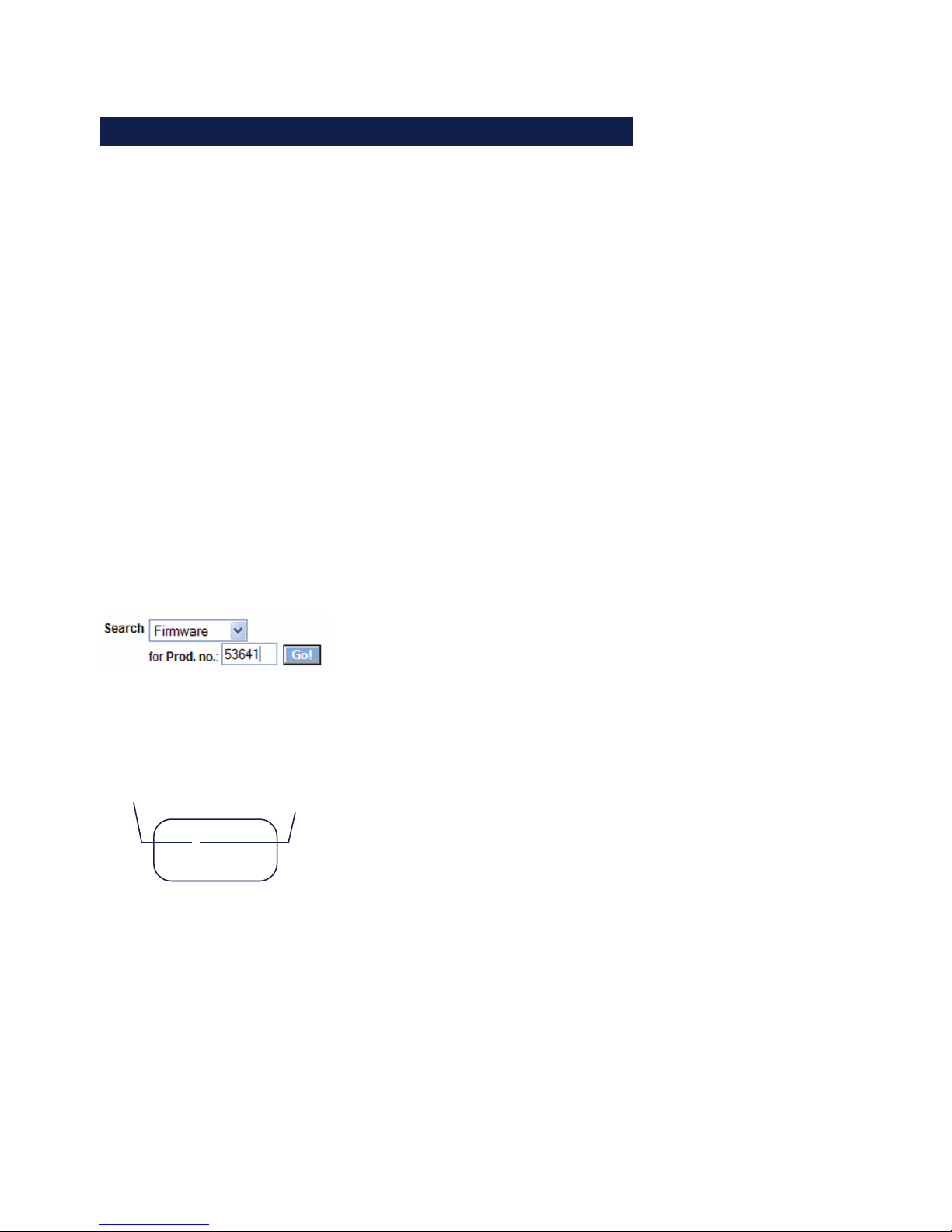
The easiest way to navigate there is to use the Search function
on the left side. First enter the model number of your device in
the entry field. Select Firmware in the associated selection box
and then click on the Go button.
If you do not know the model number, you can find it on the
sticker on the narrow side of the housing. There the Ethernet
address is also printed.
Model no.
53xxx [Description]
EN=00c03d044a05
OK xxxxxx
Description (if special version
with TB number)
7.2.2 Firmware update under Windows
No special preparation of the USB-Server is necessary for the
firmware update.
Page 63

63
Subject to errors and modifications
W&T Appendix
New firmware is sent to the USB-Server using the WuTility
management tool. In the inventory list highlight the desired
USB-Server and then click on the Firmware button.
In the following dialog box you select only the firmware file you
want to send (*.uhd) and then click on the Continue button. After successful sending the USB-Server automatically performs a
restart and is then ready to use.
1
Interrupting the update process may result in failure of
thedevice. Therefore you should verify that the supply
voltage is stable and the network connection reliable before
updating.
Page 64

64
W&T Appendix
7.3 Resetting the USB-Server
If the USB-Server needs to be reset without changing its
settings, socket 8888 can be used. If a connection is opened
to this port the USB-Server immediately closes it again and then
performs a restart of the firmware.
Use of the system password
If a system password has been configured, this must be null
terminated (= [password] + 0x00) and sent to the USB-Server
within 2s after a successful connection opening. If the USB-Server receives an incorrect or no systen password within this time,
it sends the message PASSWD? followed by a null byte (0x00)
to the client and closes the TCP connection..
If no system password is configured, the USB-Server, as
described in the example, immediately closes the TCP
connection after it is opened and performs a reset.
1
After this reset all buffer contents and any currently
activeconnections are deleted/closed. This reset can be
initiated by any station and should be used only in
emergencies!
Page 65

65
Subject to errors and modifications
W&T Appendix
7.4 Reset to factory defaults
The USB-Server can be reset to its factory default settings using
the following methods.
7.4.1 Hardware reset to factory default settings
To use this method the motherboard of the USB-Server has a
jumper next to the network port. This is OUT for standard
mode.
Put this jumper IN and then connect power to the USB-Server.
After approx. 15 seconds the four LEDs USB Connect and USB
Error flash cyclically. The USB-Server is now reset to its factory
default settings and is ready to use again after removing the
jumper and after a reset.
Opening the housing
First disconnect all cables from the USB-Server. Open the DIN
rail mount housing by gently pressing on the narrow sides of
the housing. The housing cover can now be removed and the
board removed from the housing body.
7.4.2 Software reset to factory default settings
In addition to the hardware method, the USB-Server can also be
restored to its factory default settings using Web-Based-Management. After Login the Restore Factory Defaults button is
visible in the Logout menu branch.
Page 66

66
W&T Appendix
7.5 Used ports and network security
In its standard factory setting the USB-Server uses the TCP and
UDP port numbers shown in the table below.
Configurable
yes
yes
no
no
no
no
Port-/Socketnumber
32032 (TCP)
80 (TCP)
8888 (TCP)
2682 (TCP)
8513 (UDP)
69 (UDP)
Application
Data USB redirector
Web-Based-Management
Reset USB-Server
Initialize
Firmware update
Inventory
Firmware update (only after
initialized through 2682)
Password
protection?
no
yes
yes
yes
no
(yes)
1
When the factory setrting for the sevices for USB data
transmission and WBM, different TCP port numbers must
always be used.
The USB-Server and network security
Network security is being given increasing attention today, and
rightly so. All experts agree that there is no such thing as absolute security given today‘s state of the art. Each customer
must therefore seek an appropriate balance between security,
functionaltiy and cost for his specific needs and circumstances.
To give the customer the greatest possible flexibility based on
changing security requirements, from a purely testing and
installation environment to critical production applications, the
security measures are highly configurable. The present
document provides an overview of the security measures
implemented in USB-Servers which can be used. It is assumed
that the original firmware from W&T (without any customerspecific adaptations) is being used. Additional details can be
found in the respective sections of this manual.
Page 67

67
Subject to errors and modifications
W&T Appendix
The authorization concept of the USB-Server
The control and configuration access to the USB-Server is
password protected. The factory default setting is for no
password, so that simply logging in provides full access to the
corresponding settings and functions. To prevent unauthorized
access, we therefore strongly recommend using a password.
Additional related measures, such as the composition of the
password and regularly changing it, should be organizationally
ensured as needed by the customer.
Passwords are sent to the USB-Server unencrypted. It must
therefore be ensured that password-protected access takes
place only using an Intranet which the customer presumes to
be secure. For access over the public Internet additional
measures must be taken, for example constructing a VPN
tunnel (Virtual Private Network). This is however a general
problem of network security for which each customer must find
an individual solution.
Ports with special functions
In addition to access using Web Based Management, other
functions can be enabled using various TCP and UDP ports.
These are shown in the previous table. Details can be found in
the corresponding sections of this manual.
• Inventorizing tool
Like all intelligent components from W&T the USB-Server can
be accessed using the WuTility tool. Here information is
read from UDP port 8513. This port cannot be turned off.
No write access is possible through this path.
• Firmware update
(see section Firmware update)
Initializing a firmware update is handled by the system
password protected TCP port 2682. For a firmware update
only the operating system of the USB-Server is updated. The
configuration data (IP address, gateway etc.) remain intact.
Page 68

68
W&T Appendix
• Reading/writing the configuration data
(see section Up- and downloading the configuration data)
The configuration profiles can be read from and written to
USB-Servers using the WuTility tool or Web-Based-Management. In both cases this is done using the TCP port reserved
for Web-Based-Management.
• USB-Server reset
(see section Resetting the USB-Server)
TCP port 8888 permits a complete reset of the USB-Server.
The port is not configurable and is password protected.
Page 69

69
Subject to errors and modifications
W&T Appendix
7.6 Technical data
Supply voltage ...
Power over Ethernet
External supply
Current draw ...
Power over Ethernet
Ext. supply without USB devices
Ext. supply with 2 USB devices a 2,5W
Network
Galvanic isolation
USB ports
USB speed
Permissible ambient temperature ...
... storage
... operating, non-cascaded
... operating, cascaded
Permissible relative humidity
Dimensions
Weight
37 - 57V DC from PSE
DC 24V - 48V (+/-10%)
PoE Class 3 (6,49-12,95W)
typ. 50mA @24V DC
typ. 350mA @ 24V DC
10/100BaseT, autonegotiating
RJ45 STP
Network: min. 500V
2 x Type A
480 Mbit/s
-40 ... +85°C
0 ... +70°C
0 ... +60°C
0 - 95% (non condensing)
ca. 200g
105 x 75 x 22mm
Page 70

70
W&T Appendix
7.7 Licences
GNU GENERAL PUBLIC LICENSE
Version 2, June 1991
Copyright (C) 1989, 1991 Free Software Foundation, Inc.,
51 Franklin Street, Fifth Floor, Boston, MA 02110-1301 USA
Everyone is permitted to copy and distribute verbatim copies
of this license document, but changing it is not allowed.
Preamble
The licenses for most software are designed to take away your
freedom to share and change it. By contrast, the GNU General Public
License is intended to guarantee your freedom to share and change free
software--to make sure the software is free for all its users. This
General Public License applies to most of the Free Software
Foundation's software and to any other program whose authors commit to
using it. (Some other Free Software Foundation software is covered by
the GNU Lesser General Public License instead.) You can apply it to
your programs, too.
When we speak of free software, we are referring to freedom, not
price. Our General Public Licenses are designed to make sure that you
have the freedom to distribute copies of free software (and charge for
this service if you wish), that you receive source code or can get it
if you want it, that you can change the software or use pieces of it
in new free programs; and that you know you can do these things.
To protect your rights, we need to make restrictions that forbid
anyone to deny you these rights or to ask you to surrender the rights.
These restrictions translate to certain responsibilities for you if you
distribute copies of the software, or if you modify it.
For example, if you distribute copies of such a program, whether
gratis or for a fee, you must give the recipients all the rights that
you have. You must make sure that they, too, receive or can get the
source code. And you must show them these terms so they know their
rights.
Page 71

71
Subject to errors and modifications
W&T Appendix
We protect your rights with two steps: (1) copyright the software, and
(2) offer you this license which gives you legal permission to copy,
distribute and/or modify the software.
Also, for each author's protection and ours, we want to make certain
that everyone understands that there is no warranty for this free
software. If the software is modified by someone else and passed on, we
want its recipients to know that what they have is not the original, so
that any problems introduced by others will not reflect on the original
authors' reputations.
Finally, any free program is threatened constantly by software
patents. We wish to avoid the danger that redistributors of a free
program will individually obtain patent licenses, in effect making the
program proprietary. To prevent this, we have made it clear that any
patent must be licensed for everyone's free use or not licensed at all.
The precise terms and conditions for copying, distribution and
modification follow.
GNU GENERAL PUBLIC LICENSE
TERMS AND CONDITIONS FOR COPYING, DISTRIBUTION AND MODIFICATION
0. This License applies to any program or other work which contains
a notice placed by the copyright holder saying it may be distributed
under the terms of this General Public License. The "Program", below,
refers to any such program or work, and a "work based on the Program"
means either the Program or any derivative work under copyright law:
that is to say, a work containing the Program or a portion of it,
either verbatim or with modifications and/or translated into another
language. (Hereinafter, translation is included without limitation in
the term "modification".) Each licensee is addressed as "you".
Activities other than copying, distribution and modification are not
covered by this License; they are outside its scope. The act of
running the Program is not restricted, and the output from the Program
is covered only if its contents constitute a work based on the
Program (independent of having been made by running the Program).
Whether that is true depends on what the Program does.
1. You may copy and distribute verbatim copies of the Program's
Page 72

72
W&T Appendix
source code as you receive it, in any medium, provided that you
conspicuously and appropriately publish on each copy an appropriate
copyright notice and disclaimer of warranty; keep intact all the
notices that refer to this License and to the absence of any warranty;
and give any other recipients of the Program a copy of this License
along with the Program.
You may charge a fee for the physical act of transferring a copy, and
you may at your option offer warranty protection in exchange for a fee.
2. You may modify your copy or copies of the Program or any portion
of it, thus forming a work based on the Program, and copy and
distribute such modifications or work under the terms of Section 1
above, provided that you also meet all of these conditions:
a) You must cause the modified files to carry prominent notices
stating that you changed the files and the date of any change.
b) You must cause any work that you distribute or publish, that in
whole or in part contains or is derived from the Program or any
part thereof, to be licensed as a whole at no charge to all third
parties under the terms of this License.
c) If the modified program normally reads commands interactively
when run, you must cause it, when started running for such
interactive use in the most ordinary way, to print or display an
announcement including an appropriate copyright notice and a
notice that there is no warranty (or else, saying that you provide
a warranty) and that users may redistribute the program under
these conditions, and telling the user how to view a copy of this
License. (Exception: if the Program itself is interactive but
does not normally print such an announcement, your work based on
the Program is not required to print an announcement.)
These requirements apply to the modified work as a whole. If
identifiable sections of that work are not derived from the Program,
and can be reasonably considered independent and separate works in
themselves, then this License, and its terms, do not apply to those
sections when you distribute them as separate works. But when you
distribute the same sections as part of a whole which is a work based
on the Program, the distribution of the whole must be on the terms of
Page 73

73
Subject to errors and modifications
W&T Appendix
this License, whose permissions for other licensees extend to the
entire whole, and thus to each and every part regardless of who wrote it.
Thus, it is not the intent of this section to claim rights or contest
your rights to work written entirely by you; rather, the intent is to
exercise the right to control the distribution of derivative or
collective works based on the Program.
In addition, mere aggregation of another work not based on the Program
with the Program (or with a work based on the Program) on a volume of
a storage or distribution medium does not bring the other work under
the scope of this License.
3. You may copy and distribute the Program (or a work based on it,
under Section 2) in object code or executable form under the terms of
Sections 1 and 2 above provided that you also do one of the following:
a) Accompany it with the complete corresponding machine-readable
source code, which must be distributed under the terms of Sections
1 and 2 above on a medium customarily used for software interchange; or,
b) Accompany it with a written offer, valid for at least three
years, to give any third party, for a charge no more than your
cost of physically performing source distribution, a complete
machine-readable copy of the corresponding source code, to be
distributed under the terms of Sections 1 and 2 above on a medium
customarily used for software interchange; or,
c) Accompany it with the information you received as to the offer
to distribute corresponding source code. (This alternative is
allowed only for noncommercial distribution and only if you
received the program in object code or executable form with such
an offer, in accord with Subsection b above.)
The source code for a work means the preferred form of the work for
making modifications to it. For an executable work, complete source
code means all the source code for all modules it contains, plus any
associated interface definition files, plus the scripts used to
control compilation and installation of the executable. However, as a
special exception, the source code distributed need not include
anything that is normally distributed (in either source or binary
Page 74

74
W&T Appendix
form) with the major components (compiler, kernel, and so on) of the
operating system on which the executable runs, unless that component
itself accompanies the executable.
If distribution of executable or object code is made by offering
access to copy from a designated place, then offering equivalent
access to copy the source code from the same place counts as
distribution of the source code, even though third parties are not
compelled to copy the source along with the object code.
4. You may not copy, modify, sublicense, or distribute the Program
except as expressly provided under this License. Any attempt
otherwise to copy, modify, sublicense or distribute the Program is
void, and will automatically terminate your rights under this License.
However, parties who have received copies, or rights, from you under
this License will not have their licenses terminated so long as such
parties remain in full compliance.
5. You are not required to accept this License, since you have not
signed it. However, nothing else grants you permission to modify or
distribute the Program or its derivative works. These actions are
prohibited by law if you do not accept this License. Therefore, by
modifying or distributing the Program (or any work based on the
Program), you indicate your acceptance of this License to do so, and
all its terms and conditions for copying, distributing or modifying
the Program or works based on it.
6. Each time you redistribute the Program (or any work based on the
Program), the recipient automatically receives a license from the
original licensor to copy, distribute or modify the Program subject to
these terms and conditions. You may not impose any further
restrictions on the recipients' exercise of the rights granted herein.
You are not responsible for enforcing compliance by third parties to
this License.
7. If, as a consequence of a court judgment or allegation of patent
infringement or for any other reason (not limited to patent issues),
conditions are imposed on you (whether by court order, agreement or
otherwise) that contradict the conditions of this License, they do not
excuse you from the conditions of this License. If you cannot
distribute so as to satisfy simultaneously your obligations under this
Page 75

75
Subject to errors and modifications
W&T Appendix
License and any other pertinent obligations, then as a consequence you
may not distribute the Program at all. For example, if a patent
license would not permit royalty-free redistribution of the Program by
all those who receive copies directly or indirectly through you, then
the only way you could satisfy both it and this License would be to
refrain entirely from distribution of the Program.
If any portion of this section is held invalid or unenforceable under
any particular circumstance, the balance of the section is intended to
apply and the section as a whole is intended to apply in other
circumstances.
It is not the purpose of this section to induce you to infringe any
patents or other property right claims or to contest validity of any
such claims; this section has the sole purpose of protecting the
integrity of the free software distribution system, which is
implemented by public license practices. Many people have made
generous contributions to the wide range of software distributed
through that system in reliance on consistent application of that
system; it is up to the author/donor to decide if he or she is willing
to distribute software through any other system and a licensee cannot
impose that choice.
This section is intended to make thoroughly clear what is believed to
be a consequence of the rest of this License.
8. If the distribution and/or use of the Program is restricted in
certain countries either by patents or by copyrighted interfaces, the
original copyright holder who places the Program under this License
may add an explicit geographical distribution limitation excluding
those countries, so that distribution is permitted only in or among
countries not thus excluded. In such case, this License incorporates
the limitation as if written in the body of this License.
9. The Free Software Foundation may publish revised and/or new versions
of the General Public License from time to time. Such new versions will
be similar in spirit to the present version, but may differ in detail to
address new problems or concerns.
Each version is given a distinguishing version number. If the Program
specifies a version number of this License which applies to it and "any
Page 76

76
W&T Appendix
later version", you have the option of following the terms and conditions
either of that version or of any later version published by the Free
Software Foundation. If the Program does not specify a version number of
this License, you may choose any version ever published by the Free Software
Foundation.
10. If you wish to incorporate parts of the Program into other free
programs whose distribution conditions are different, write to the author
to ask for permission. For software which is copyrighted by the Free
Software Foundation, write to the Free Software Foundation; we sometimes
make exceptions for this. Our decision will be guided by the two goals
of preserving the free status of all derivatives of our free software and
of promoting the sharing and reuse of software generally.
NO WARRANTY
11. BECAUSE THE PROGRAM IS LICENSED FREE OF CHARGE, THERE IS NO WARRANTY
FOR THE PROGRAM, TO THE EXTENT PERMITTED BY APPLICABLE LAW. EXCEPT WHEN
OTHERWISE STATED IN WRITING THE COPYRIGHT HOLDERS AND/OR OTHER PARTIES
PROVIDE THE PROGRAM "AS IS" WITHOUT WARRANTY OF ANY KIND, EITHER EXPRESSED
OR IMPLIED, INCLUDING, BUT NOT LIMITED TO, THE IMPLIED WARRANTIES OF
MERCHANTABILITY AND FITNESS FOR A PARTICULAR PURPOSE. THE ENTIRE RISK AS
TO THE QUALITY AND PERFORMANCE OF THE PROGRAM IS WITH YOU. SHOULD THE
PROGRAM PROVE DEFECTIVE, YOU ASSUME THE COST OF ALL NECESSARY SERVICING,
REPAIR OR CORRECTION.
12. IN NO EVENT UNLESS REQUIRED BY APPLICABLE LAW OR AGREED TO IN WRITING
WILL ANY COPYRIGHT HOLDER, OR ANY OTHER PARTY WHO MAY MODIFY AND/OR
REDISTRIBUTE THE PROGRAM AS PERMITTED ABOVE, BE LIABLE TO YOU FOR DAMAGES,
INCLUDING ANY GENERAL, SPECIAL, INCIDENTAL OR CONSEQUENTIAL DAMAGES ARISING
OUT OF THE USE OR INABILITY TO USE THE PROGRAM (INCLUDING BUT NOT LIMITED
TO LOSS OF DATA OR DATA BEING RENDERED INACCURATE OR LOSSES SUSTAINED BY
YOU OR THIRD PARTIES OR A FAILURE OF THE PROGRAM TO OPERATE WITH ANY OTHER
PROGRAMS), EVEN IF SUCH HOLDER OR OTHER PARTY HAS BEEN ADVISED OF THE
POSSIBILITY OF SUCH DAMAGES.
END OF TERMS AND CONDITIONS
Page 77

77
Subject to errors and modifications
W&T Appendix
Page 78

78
W&T Index
Index
Symbole
10/100BaseT 33
A
air circulation 8
authorization concept 67
Auto Negotiation 34
B
Bulk transfer 35
C
Client 44
configuration session 52
conflict protection 47
Connect LED 36
Control transfer 35
D
default IP address 11
Description 44
DHCP 20, 21, 22, 55
downloading configuration 60
E
Error LED 37
Ethernet port 33
F
Factory defaults 65
Firmware update 62
Full duplex 34
Full speed 35
G
Gateway 56
H
Half Duplex 34
High speed 35
Hot plugging 35
HTTP port 56
I
Identification 44
Installation 8
Interrupt transfer 35
Inventory list 44
IP address 19, 56
Isochronal transfer 35
K
Keep alive check 57
L
Lease time 23
Low speed 35
N
Network connection 9
network parameter 11
Network parameters 55
Network security 66
O
Opening the housing 65
P
password 54
Plug 47
PoE 33
Port 44
Port numbers 40
Power LED 36
Power management 32
Power over Ethernet 33
Power supply 9, 32
Page 79

79
W&T Index
Q
Quickstart 7
R
Requested USB device 44
Reset 65
RJ45 33
S
Static IP 21, 26, 55
Status 44
Status LED 36
Subnet mask 56
System Name 23
System Overview 15
T
Technical data 69
U
Unplug 48
USB interface 35
USB modes 16
USB port 10, 16, 35
USB Port Redirector 12, 40
UsbServerPort 40, 56
Using USB devices 47
W
WBM 50
WBM - Login 52
WBM - Logout 53
WuTility 11, 26
X
XML format 60
 Loading...