

Page 1
W&T
Manual
USB Isolator
Release 1.0
Model 33001
Page 2

10
W&T USB Isolators
© 09/2010 by Wiesemann & Theis GmbH
Subject to errors and changes:
Since we can make mistakes, none of our statements should be
used without checking. Please let us know of any mistakes or
misunderstandings you are aware of, so that we can recognize
and eliminate them quickly.
Perform work on and with W&T products only as described here
and only if you have read and understood the manual fully.
Unauthorized use can result in hazards. We are not liable for
the consequences of unauthorized use. When in doubt, check
with us or consult you dealer!
Page 3

11
W&T
Subject to error and alteration
USB Isolators
USB interfaces in stationary computers unfortunately have the
basic drawback of having no galvanic isolation for the signal
lines.
In many applications in the consumer world this limitation is
irrelevant, since the USB devices connected to the PC are
generally supplied through the bus and do not have any
reference to a second ground or to the ground conductor.
In the areas of measurement reading, process control or for
example medical technology, galvanic isolation of the
connected devices is mandatory in order to prevent ground
loops on the USB line.
Wiesemann & Theis therefore offers an USB Isolator which is
described on the following pages along with his technical
specification and a wiring example.
For up-to-date information on new developments on the Internet, go to
http://www.wut.de or the e-mail short infos available
from the W&T Interface Club, which you can sign up for at the
W&T Homepage.
Page 4

12
W&T USB Isolators
Contents
USB Isolator, 1kV, #33001 ................................................... 13
Function ............................................................................ 13
Supply voltage ................................................................... 13
Display Elements ................................................................ 14
Speed configuration ........................................................... 14
Wiring Example ................................................................... 15
Technical Data ................................................................... 16
Page 5

13
W&T
Subject to error and alteration
USB Isolators
USB Isolator, 1kV, #33001
Function
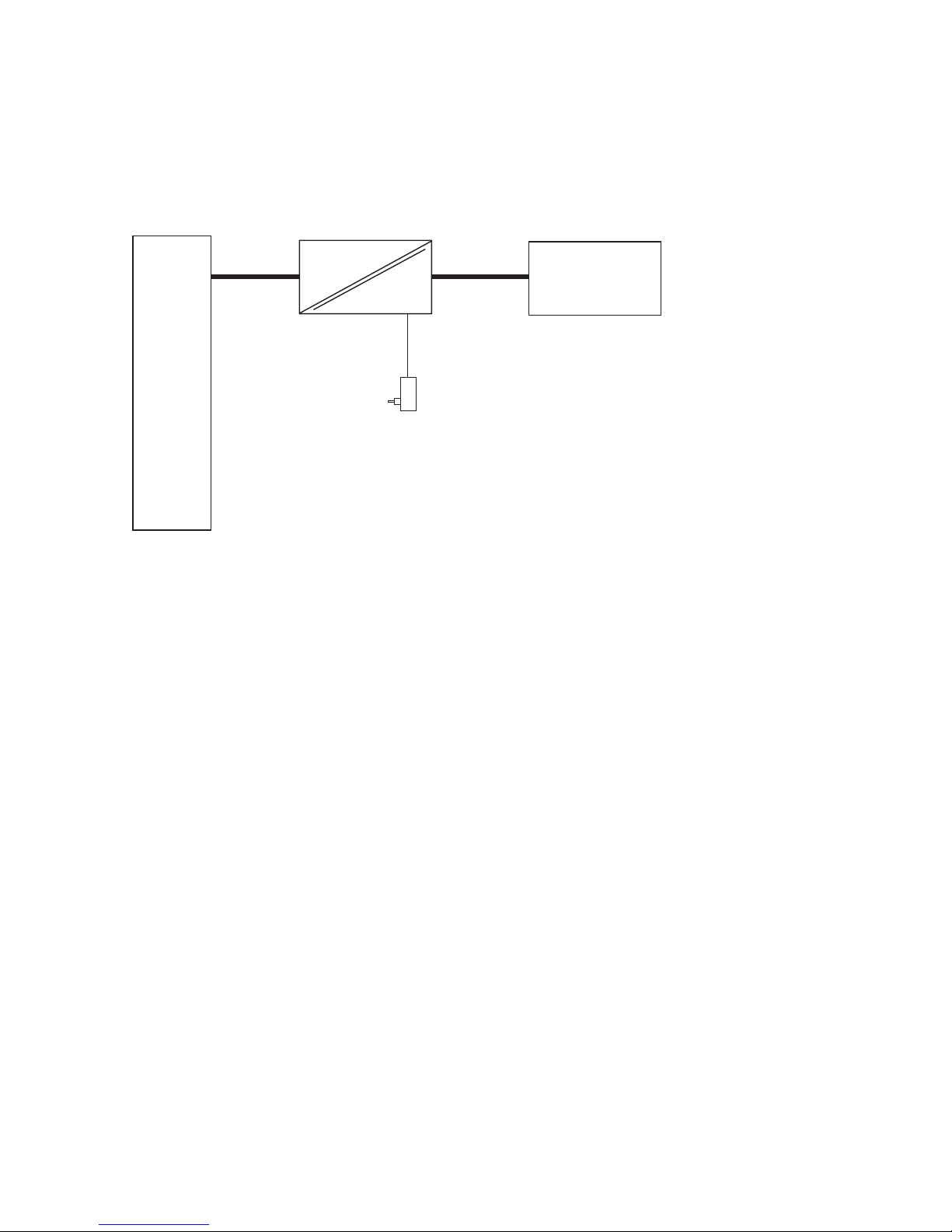
The Wiesemann & Theis USB-Isolator #33001 provides galvanic
isolation for low-speed and full-speed USB connections with an
isolation voltage of at least 1000V DC. The Isolator eliminates
ground loops and prevents current from flowing between the
connected devices and the supply lines of the USB caused by
potential differences. The Isolator is simply inserted into the
existing USB connection and powered by an external power
supply.
Supply voltage
The USB Isolator requires an external power supply for
powering the galvanically isolated Isolator side and a buspowered terminal device.
A suitable wall mount adaptor is included with the Isolator.
In principle any 5V DC power supply with a USB output can be
used as long as it provides an output current of at least 0.5A.
The supply voltage is brought to the Isolator side through a
mini-USB socket. The socket is marked on the Isolator as
„Power Connector.“ An appropriate adapter cable for connecting the power supply is also included with the Isolator.
The USB A plug on the power cable must never be
connected to a second USB port on the USB host or hub
which is connected to the upstream port of the Isolator.
Such a connection would jumper the galvanic isolation
and make it ineffective. A galvanically isolated voltage
source is therefore absolutely mandatory.
1
Page 6
14
W&T USB Isolators
W&T
www.WuT.de
USB Isolator
1kV
#33001
Power IN
Power OUT
IN
OUT
Power
Connector
Full Speed
Low Speed
USB A
socket
USB A
plug
USB cable
0,2m
Display elements
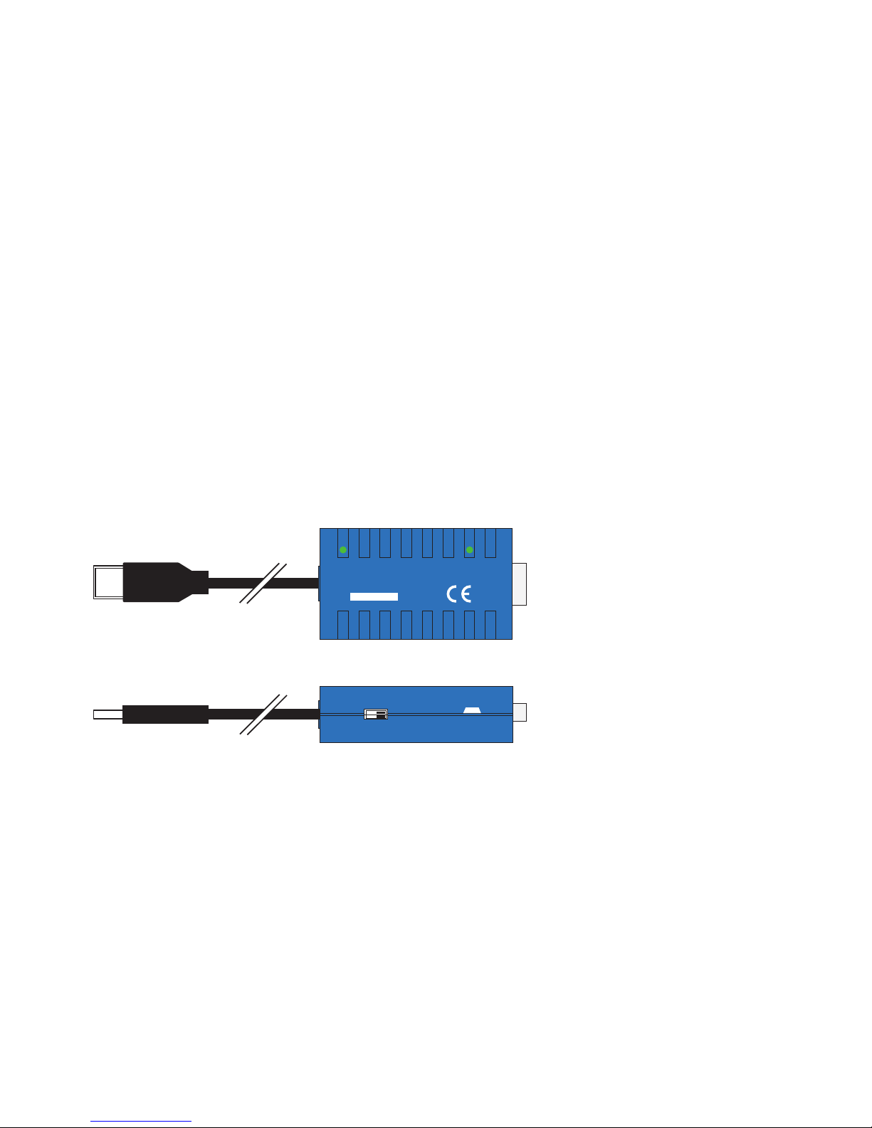
The Isolator includes two green LEDs for indicating the correct
supply voltage for the Isolator. The Power IN LED indicates
correct power for the upstream side of the Isolator from the USB
host or hub, whereas the Power Out LED indicates the voltage
of the downstream side.
Speed switching
The USB-Isolator #33001 supports USB devices operating in
low-speed mode at 1.5 MBit/s or full-speed mode at 12 MBit/s.
Two small switches on the side of the Isolator labeled „Low
Speed“ and „Full Speed“ are used to switch between the two
speeds.
Each switch configures the upstream and downstream side of
the Isolator. Since a speed conversion with the Isolator is not
technically realizable, both switches must always be in the same
position. The Isolator will not function with the switches in different positions.
The factory default setting for the Isolator is Full Speed mode.
Page 7
15
W&T
Subject to error and alteration
USB Isolators
Wiring example
USB-Isolator
#33001
USB
host
or
USB
hub
USB
USB
upstream port
(USB A plug)
downstream port
(USB A - socket)
USB
slave
Power adaptor 5V, 0,7A
min. 1kV galvanic isolation
Mini USB
connector
Page 8

16
W&T USB Isolators
Technical data
USB speed: Configurable:
Full Speed (12MBit/s),
Low Speed (1.5 MBIt/s)
Isolation voltage: min. 1kV DC (high isolation
voltages on request)
Power: Upstream-Port: USB-supplied
Downstream-Port: 5V DC using
included power supply
Current draw: Upstream-Port: max. 8 mA
Downstream-Port: max. 8 mA plus
current draw of the USB slave
USB connections: Upstream-Port: USB A plug
with 20 cm cable
Downstream-Port: USB A socket integrated in housing
Ambient temperature: Isolator: Storage: -40..+70°C,
operating: 0..+70°C
Power supply: Storage: -40..+70°C,
operating: 0..+40°C
Permissible rel. humidity: 0..90%
(non-condensing)
Housing: Plastic compact housing,
55 x 30 x 16 mm
Weight: approx. 35 g
Scope of delivery: USB Isolator
USB power supply 5V / 0.7A
power cable, Mini-USB, 5-pin
 Loading...