

Page 1

51
W&T
Interface modules
Subject to error and alteration
Manual
Interface modules
Model 18801, 18811
18802, 18812
18803, 18813
18601, 18611
18602, 18612
18401, 18411
18402, 18412
18101, 18111
18120, 18121
18311
Version 1.4
W&T
Page 2

52
W&T
Interface modules
© 07/2006 by Wiesemann und Theis GmbH
Subject to error and alteration:
Since it is posssible that we make mistakes, you mustn’t use
any of our statements without verification. Please, inform us of
any error or misunderstanding you come about, so we can
identify and eliminate it as soon as possible.
Carry out your work on or with W&T products only to the
extent that they are described here and after you have
completely read and understood the manual or guide. We are
not liable for unauthorized repairs or tampering. When in
doubt, check first with us or with your dealer.
Page 3

53
W&T
Interface modules
Subject to error and alteration
The modular design of all W&T Com-Servers as well as most of
the W&T PC cards allows them to be equipped with
various serial interface types.
Modification of the standard units is accomplished by
simply exchanging the existing interface modules with
modules of the desired interface type.
The W&T interface module family is described on the
following pages along with the corresponding technical data
and including connection examples.
For up-to-date information on new developments, see our
Internet site at
http://www.wut.de or check the e-mail short
notices at the W&T Interface Club, which you can also
subscribe to from the W&T Homepage.
Page 4

54
W&T
Interface modules
Index
Inhalt
Common characteristics and mechanical details ................... 55
RS232 DTE Interface Modules, Model 188x1 ......................... 57
RS232 DCE Interface Modules, Model 188x2 ......................... 59
RS232/RS422/RS485 Interface Modules, Model 188x3 .......... 61
RS422/RS485 Interface Modules, Model 186x1 ..................... 69
Profibus Interface Modules, Model 186x2 ............................ 77
20mA Interface Modules, Model 184x1 ................................ 81
20mA Interface Modules, Model 184x2 ................................ 85
POF Interface Modules, Model 181x1 ................................... 89
Fiber Optic Interface Modules, Model 1812x ........................ 93
USB Interface Module, Model 18311 ..................................... 97
Page 5
55
W&T
Interface modules
Subject to error and alteration
Common characteristics and mechanical details
Many W&T Interfaces are characterized by modular construction
with a strict division into basic and interface electronics, so that
changing out the integrated, plug-in Interface Modules allows
you to freely select the interface type for the device.
In addition you can use the W&T Interface Modules to equip
third-party devices which only have a serial TTL interface with
various standard interfaces: RS232, RS422, RS485, 20mA,
plastic fiber optics, glass fiber optics and USB.
There are two different series of W&T Interface Modules (series
18x0x and 18x1x) which differ only in the arrangement of the
connector for the serial TTL port, but which are otherwise
identical in function.
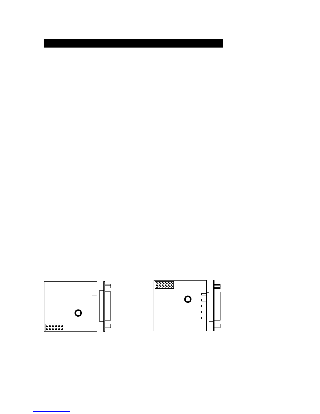
All W&T Interface Modules have a 12-pin 2mm header and a
central hole for screwing the module to the associated motherboard. The pin configuration for the TTL interface can be found
in the corresponding sections for the individual Module
descriptions.
The position of pin 1 of the header, which is additionally
indicated by a square solder pad, as well as the numbering
order of the connector pins, can be seen for both Module
series in the following diagram:
18x0x
1
6
7
12
18x1x
1
6
7
12
Page 6
56
W&T
Interface modules
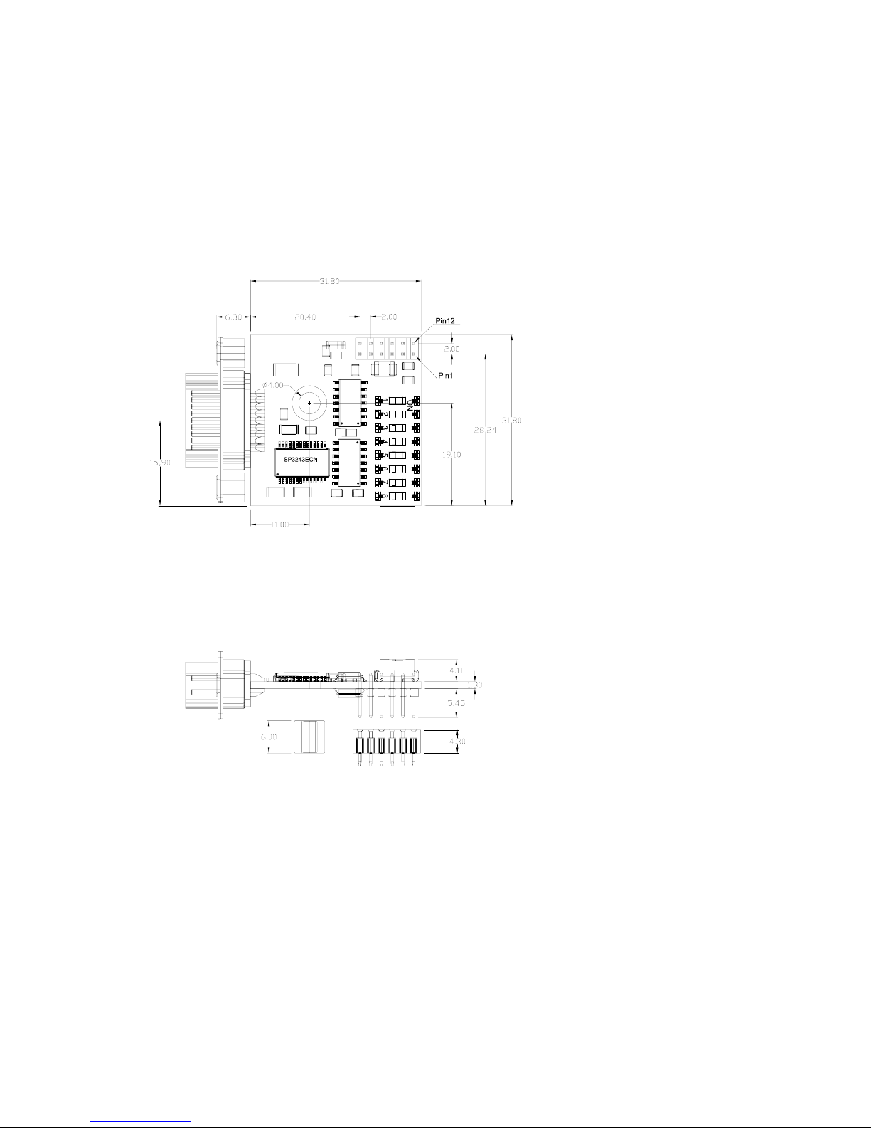
Dimensional drawing
The following drawing indicates the dimensions of the Module
as well as the position of the connectors and attachment
points. Shown in the drawing is the Combi-Module 18833, but
the dimensions apply to all Modules with SUB-D connector.
Important installation note
When installing or replacing the Interface Modules, visually
inspect to ensure that the module does not cause a short
circuit with adjacent components. To use the Interface
Modules with W&T PC cards, remove the wire jumper between
the SUB-D male connector housing and the module. Otherwise
the galvanic isolation between the interface and the PC may be
defeated.
1
Page 7

57
W&T
Interface modules
Subject to error and alteration
RS232 DTE Interface Modules, #188x1
Function
The W&T Interface Modules 18801 and 18811 provide an
RS232 DTE interface for devices equipped with a serial TTL port.
The modules support all RS232 data and handshaking signals.
Modules 18801 and 18811 differ only in the arrangement of
the post connector for the serial TTL port, and are in every
other respect functionally identical.
Important installation note
When installing or replacing the Interface Modules, visually
inspect to ensure that the module does not cause a short
circuit with adjacent components. To use the Interface Modules with W&T PC cards, remove the wire jumper between the
SUB-D male connector housing and the module. Otherwise the
galvanic isolation between the interface and the PC may be
defeated.
Supply voltage
The Interface Modules require a regulated supply voltage of
5V DC ±5%. The no-load current draw of the modules is
approx. 30mA (typ.); any additional current requirement from
an external load must of course be taken into account when
dimensioning the power supply.
Protection against static charges
All external signal lines use ESD-immune interface components
to provide protection against static discharges of up to 15kV
per IEC 801-2, Level 4.
1
Page 8
58
W&T
Interface modules
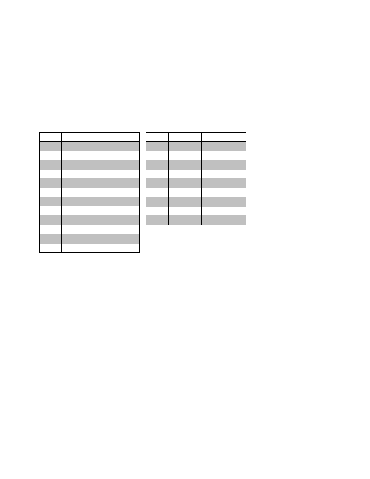
Pin configuration
The RS232 connection for the modules is configured as a
9-pin male SUB-D connector, with the TTL interface formatted
as 12-pin male post connector. Refer to the following
table for connector pin assignments:
TTL interface RS232 interface
pin# signal function
1 5V ±5% Vcc
2 RI output
3 RxD output
4 TxD input
5 n.c. n.c.
6 CTS output
7 DTR input
8 DSR output
9 RTS input
10 DCD output
11 12V ±10% n.c.
12 GND signal GND
Pin 1 of the TTL interface is indicated by a rectangular soldering pad.
Technical Data
Baud rate: 0..230 KBaud
Data format: any
Supported signals: RxD, TxD, RTS, CTS, DSR, DCD, DTR, RI
ESD immunity: up to 15kV per IEC 801-2,
Level 4 using ESD-immune
interface components
Supply voltage: 5V DC ±5%
Supply current: approx. 30mA
TTL connector: 12-pin, 2mm post connector
RS232 connector: 9-pin male SUB-D connector
Dimensions: 43 x 31 mm
Weight: approx. 10g
Packing list: RS232 DTE Interface Module
pin# signal function
1 DCD input
2 RxD input
3 TxD output
4 DTR output
5 GND GND
6 DSR input
7 RTS output
8 CTS input
9 RI input
Page 9

59
W&T
Interface modules
Subject to error and alteration
RS232 DCE Interface Modules, #188x2
Function
The W&T Interface Modules 18802 and 18812 provide an
RS232 DCE interface for devices equipped with a serial TTL port.
The modules support all RS232 data and handshaking signals.
Modules 18802 and 18812 differ only in the arrangement of
the post connector for the serial TTL port, and are in every
other respect functionally identical.
Important installation note
When installing or replacing the Interface Modules, visually
inspect to ensure that the module does not cause a short
circuit with adjacent components.
Supply voltage
The Interface Modules require a regulated supply voltage of
5V DC ±5%. The no-load current draw of the modules is
approx. 30mA (typ.); any additional current requirement from
an external load must of course be taken into account when
dimensioning the power supply.
Protection against static charges
All external signal lines use ESD-immune interface components
to provide protection against static discharges of up to 15kV
per IEC 801-2, Level 4.
1
Page 10

60
W&T
Interface modules
Pin configuration
The RS232 connection for the modules is configured as a
9-pin female SUB-D connector, with the TTL interface formatted
as 12-pin male post connector. Refer to the following
table for connector pin assignments:
TTL interface RS232 interface
pin# signal function
1 5V ±5% Vcc
2 RI input
3 TxD output
4 RxD input
5 n.c. n.c.
6 DTR output
7 CTS input
8 DSR input
9 RTS output
10 DCD input
11 12V ±10% n.c.
12 GND signal GND
Pin 1 of the TTL interface is indicated by a rectangular soldering pad.
Technical Data
Baud rate: 0..230 KBaud
Data format: any
Supported signals: RxD, TxD, RTS, CTS,
DSR, DCD, DTR, RI
ESD immunity: up to 15kV per IEC 801-2,
Level 4 using ESD-immune
interface components
Supply voltage: 5V DC ±5%
Supply current: approx. 30mA
TTL connector: 12-pin, 2mm post connector
RS232 connector: 9-pin female SUB-D connector
Dimensions: 43 x 31 mm
Weight: approx. 10g
Packing list: RS232 DCE Interface Module
pin# signal function
1 DCD output
2 RxD output
3 TxD input
4 DTR input
5 GND GND
6 DSR output
7 RTS input
8 CTS output
9 RI output
Page 11

61
W&T
Interface modules
Subject to error and alteration
RS232/RS422/RS485 Interface Modules, #188x3
Function
The W&T Interface Modules 18803, 18813 and 18833
provide an RS232, RS422 or RS485 interface for devices
equipped with a serial TTL port. The Interface Module is
configurable for the various operating modes via an
8-position DIL switch. Modules 18803 and 18813/18833
differ only in the arrangement of the post connector for the
serial TTL port, and are in every other respect functionally
identical.
Important installation note
When installing or replacing the Interface Modules, visually
inspect to ensure that the module does not cause a short
circuit with adjacent components. To use the Interface
Modules with W&T PC cards, remove the wire jumper between
the SUB-D male connector housing and the module. Otherwise
the galvanic isolation between the interface and the PC may be
defeated.
Supply voltage
The Interface Modules require a regulated supply voltage of
5V DC ±5% (18803 and 18813) and 3,3V DC ±5% (18833)
respectively. The no-load current draw of the modules is
approx. 40mA (typ.); any additional current requirement from
an external load must of course be taken into account when
dimensioning the power supply.
Protection against static charges
All external signal lines use ESD-immune interface components
to provide protection against static discharges of up to 15kV
per IEC 801-2, Level 4.
1
Page 12

62
W&T
Interface modules
Pin 1 of the TTL interface is indicated by a rectangular soldering pad.
RS232 interface RS422/RS485 interface
Pin configuration
The RS232/RS422/RS485 connection for the modules is
configured as a 9-pin male SUB-D connector, with the TTL
interface formatted as 12-pin male post connector. Refer to the
following table for connector pin assignments:
TTL interface
pin# signal function
1 TXD A output
2 RxD A input
3 DTR A output
4 CTS A input
5 GND GND
6 TXD B output
7 RxD B input
8 DTR B output
9 CTS B input
pin# signal RS232 RS422/485
1 5V ±5% Vcc Vcc
2 RI output "low" level
3 RxD output output
4 TxD input input
5 n.c. n.c. n.c.
6 CTS output output
7 DTR input input
8 DSR output "low" level
9 RTS input input
10 DCD output "low" level
11 12V ±10% n.c. n.c.
12 GND signal GND signal GND
pin# signal function
1 DCD input
2 RxD input
3 TxD output
4 DTR output
5 GND GND
6 DSR input
7 RTS output
8 CTS input
9 RI input
Page 13

63
W&T
Interface modules
Subject to error and alteration
Operating modes
The Interface Modules are configurable for the following
modes using DIL switches:
RS232
The Interface Module converts all available TTL data and handshake signals into RS232 signals. This mode provides one RxD
and TxD channel each in the respective direction, along with
six handshake channels (RTS, CTS, DSR, DCD, DTR and RI).
RS422
The Interface Module supports one data and one handshake
channel each (selectable DTR or RTS handshake output). The
RS422 sender/receivers are always active.
RS485
One data channel in each direction is always available in all
RS485 modes. These modes differ only in how the RS485
transceivers are controlled.
RS485 4-wire bus master
In this mode the master uses a conductor pair to send
requests to the slaves, which in turn send their replies to the
master on an additional common conductor pair. The RS485
transceivers are always active in this mode, whereby the master
can always send and is constantly listening for the slaves.
Page 14

64
W&T
Interface modules
RS485 4-wire mode with handshake control
The RS485 driver chip is turned on with a TTL Low level on the
„DTR“ or „RTS“ line, whereas a TTL High level on this line puts
the driver in a high-impedance state. The receiving channel in
this mode is always active.
RS485 2-wire mode with handshake control
The RS485 driver chip is turned on with a TTL Low level on the
„DTR“ or „RTS“ line, whereas a TTL High level on this line puts
the driver in a high-impedance state. The receiving channel is
deactivated when the driver is on, and enabled when the driver
is in the high-impedance state.
RS485 4-wire mode with automatic control
The RS485 driver chip is automatically activated whenever data
are output and brought to the high-impedance state when data
output is finished. The receiving channel in this mode is always
active.
RS485 2-wire mode with automatic control
The RS485 driver chip is automatically activated when data are
output and brought to the high-impedance state when data
output is finished. The receiving channel is deactivated when
the driver is turned on, and enabled when the driver is in the
high-impedance state.
Page 15
65
W&T
Interface modules
Subject to error and alteration
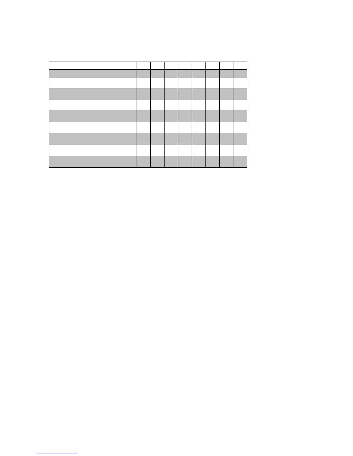
The DIL switch settings can be found in the following table:
*
*) Terminating the bus system when required.
Important Note
The terminating DIL switches SW6 and SW7 must never be in
the ON position when using the module in RS232 mode. This
will result in a significant increase in the current draw and may
cause the RS232 driver to fail.
1
Operating mode SW1 SW2 SW3 SW4 SW5 SW6 SW7 SW8
RS232 OFF OFF OFF OFF OFF OFF OFF ON
RS422, RS485, 4-wire bus master
DTR handshake
OFF OFF OFF ON OFF
**
OFF
RS422, RS485, 4-wire bus master
RTS handshake
OFF OFF OFF OFF ON
**
OFF
RS485, 4-wire / 2-wire with echo
DTR control
OFF OFF ON ON OFF
**
OFF
RS485, 2-wire without echo
DTR control
ON OFF ON ON OFF
**
OFF
RS485, 4-wire / 2-wire with echo
RTS control
OFF OFF ON OFF ON
**
OFF
RS485, 2-Draht without echo
RTS control
ON OFF ON OFF ON
**
OFF
RS485, 4-wire / 2-wire with echo
automatic control
OFF ON OFF ON OFF
**
OFF
RS485, 2-wire without echo
automatic control
ON ON OFF ON O FF
**
OFF
Page 16

66
W&T
Interface modules
Termination
All RS485 modes require termination of the bus system with a
termination network. The resistor combination integrated in the
module performs two tasks in RS485 applications:
1. The connected line is terminated corresponding to its
impedance, which prevents signal reflections at the cable end.
2. In the high-impedance phases of bus operation a defined
quiescent state is ensured.
The bus system is allowed to be terminated with the termination network only in RS485 and RS422 modes, but not in RS232
mode.
Closing DIL switches 6 and 7 on the Interface Module
connects the bus terminals to the following resistance
network:
120Ω
+5V
SW6
SW7
Data In B
Data In A
330Ω330Ω
Page 17

67
W&T
Interface modules
Subject to error and alteration
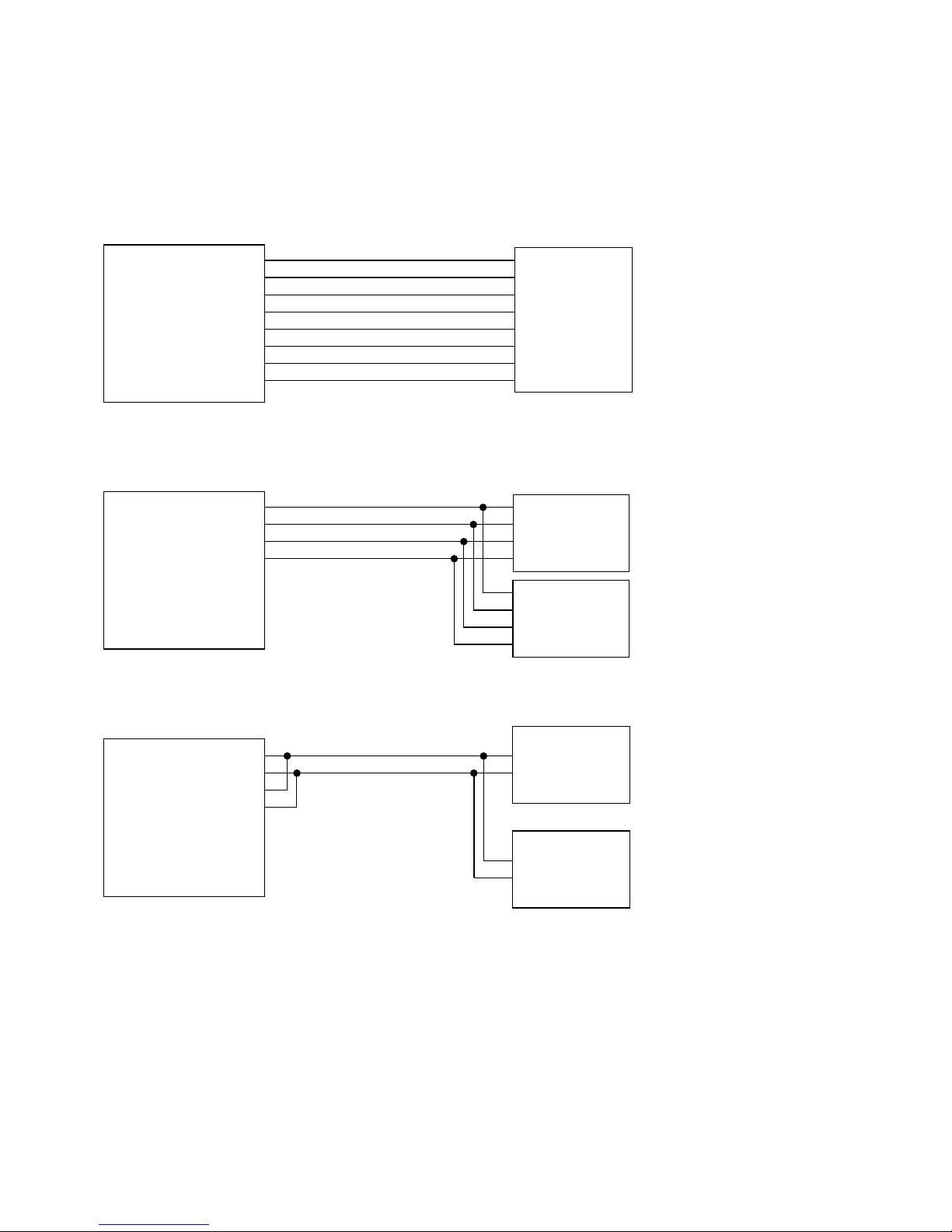
Connection examples
Bus A (-)
Bus B (+)
Bus A (-)
Bus B (+)
RS485 2-wire application
Data Out A
Data Out B
Data In A
Data In B
RS485 interface
1
6
2
7
Interface-Modul
188x3
RS485
device
RS485
device
Data Out A
Data Out B
Data In A
Data In B
RS485 interface
1
6
2
7
RxD A (-)
RxD B (+)
TxD A (-)
TxD B (+)
RxD A (-)
RxD B (+)
TxD A (-)
TxD B (+)
RS485
device
RS485 4-wire bus master application
Interface-Modul
188x3
RS485
device
RxD A (-)
RxD B (+)
TxD A (-)
TxD B (+)
CTS A (-)
CTS B (+)
RTS A (-)
RTS B (+)
RS422
device
RS422 application with hardware handshake
Data Out A
Data Out B
Data In A
Data In B
Handshake Out A
Handshake Out B
Handshake In A
Handshake In B
RS422 interface
Interface-Modul
188x3
1
6
2
7
3
8
4
9
Modem
RS232 application with hardware handshake
DCD
RxD
TxD
DTR
GND
DSR
RTS
CTS
RI
RS232 interface
Interface-Modul
188x3
1
2
3
4
5
6
7
8
9
DCD
RxD
TxD
DTR
GND
DSR
RTS
CTS
RI
8
3
2
20
7
6
4
5
22
Page 18

68
W&T
Interface modules
Technical Data
Operating modes: RS232, RS422
RS485 2- or 4-wire
Baud rate: RS232: 0..230 KBaud
RS422: 0..10 MBaud
RS485: 0..5 MBaud
Data format: any
Supported signals: RS232: RxD, TxD, RTS, CTS
DSR, DCD, DTR, RI
RS422: RxD A/B, TxD A/B
CTS A/B, DTR A/B
RS485: RXD A/B, TxD A/B
ESD immunity: up to 15kV per IEC 801-2,
Level 4 using ESD-immune
interface components
Supply voltage: 5V DC ±5% (18803, 18813)
3,3V DC ±5% (18833)
Supply current: approx. 40mA
TTL connector: 12-pin, 2mm post connector
RS232/422/485 connector: 9-pin male SUB-D connector
Dimensions: 43 x 31 mm
Weight: approx. 10g
Packing list: RS232/RS422/RS485
Interface Module
Page 19

69
W&T
Interface modules
Subject to error and alteration
RS422/RS485 Interface Modules, #186x1
Function
The W&T Interface Modules 18601 and 18611 provide an
RS422 or RS485 interface for devices equipped with a serial TTL
port. The Interface Module is configurable for the various
operating modes via an 8-position DIL switch. Modules 18601
and 18611 differ only in the arrangement of the post
connector for the serial TTL port, and are in every other respect
functionally identical.
Important installation note
When installing or replacing the Interface Modules, visually
inspect to ensure that the module does not cause a short
circuit with adjacent components. To use the Interface Modules with W&T PC cards, remove the wire jumper between the
SUB-D male connector housing and the module. Otherwise the
galvanic isolation between the interface and the PC may be
defeated.
Supply voltage
The Interface Modules require a regulated supply voltage of
5V DC ±5%. The no-load current draw of the modules is
approx. 40mA (typ.); any additional current requirement from
an external load must of course be taken into account when
dimensioning the power supply.
Protection against static charges
All external signal lines use ESD-immune interface components
to provide protection against static discharges of up to 15kV
per IEC 801-2, Level 4.
1
Page 20

70
W&T
Interface modules
Pin 1 of the TTL interface is indicated by a rectangular soldering pad.
Pin configuration
The RS422/RS2485 connection for the modules is configured
as a 9-pin male SUB-D connector, with the TTL interface formatted as 12-pin male post connector. Refer to the following table
for connector pin assignments:
TTL interface RS422/RS485 interface
pin# signal function
1 5V ±5% Vcc
2 RI "low" level
3 RxD output
4 TxD input
5 n.c. n.c.
6 CTS output
7 DTR input
8 DSR conn. to CTS
9 RTS input
10 DCD "low" level
11 12V ±10% n.c.
12 GND signal GND
pin# signal
1 TXD A
2 RxD A
3 DTR A
4 CTS A
5GND
6 TXD B
7 RxD B
8 DTR B
9 CTS B
Page 21

71
W&T
Interface modules
Subject to error and alteration
Operating modes
The Interface Modules are configurable for the following
modes using DIL switches:
RS422
The Interface Module supports one data and one handshake
channel each (selectable DTR or RTS handshake output). The
RS422 sender/receivers are always active.
RS485
One data channel in each direction is always available in all
RS485 modes. These modes differ only in how the RS485
transceivers are controlled.
RS485 4-wire bus master
In this mode the master uses a conductor pair to send
requests to the slaves, which in turn send their replies to the
master on an additional common conductor pair. The RS485
transceivers are always active in this mode, whereby the master
can always send and is constantly listening for the slaves.
RS485 4-wire mode with handshake control
The RS485 driver chip is turned on with a TTL Low level on the
„DTR“ or „RTS“ line, whereas a TTL High level on this line puts
the driver in a high-impedance state. The receiving channel in
this mode is always active.
Page 22

72
W&T
Interface modules
RS485 2-wire mode with handshake control
The RS485 driver chip is turned on with a TTL Low level on the
„DTR“ or „RTS“ line, whereas a TTL High level on this line puts
the driver in a high-impedance state. The receiving channel is
deactivated when the driver is on, and enabled when the driver
is in the high-impedance state.
RS485 4-wire mode with automatic control
The RS485 driver chip is automatically activated whenever data
are output and brought to the high-impedance state when data
output is finished. The receiving channel in this mode is always
active.
RS485 2-wire mode with automatic control
The RS485 driver chip is automatically activated when data are
output and brought to the high-impedance state when data
output is finished. The receiving channel is deactivated when
the driver is turned on, and enabled when the driver is in the
high-impedance state.
The DIL switch settings can be found in the following table:
*) Terminating the bus system when required.
Page 23

73
W&T
Interface modules
Subject to error and alteration
Termination
All RS485 modes require termination of the bus system with a
termination network. The resistor combination integrated in the
module performs two tasks in RS485 applications:
1. The connected line is terminated corresponding to its
impedance, which prevents signal reflections at the cable end.
2. In the high-impedance phases of bus operation a defined
quiescent state is ensured.
Closing DIL switches 6 and 7 on the Interface Module
connects the bus terminals to the following resistance
network:
120Ω
+5V
SW6
SW7
Data In B
Data In A
330Ω330Ω
Page 24
74
W&T
Interface modules
Connection examples
Bus A (-)
Bus B (+)
Bus A (-)
Bus B (+)
RS485 2-wire application
Data Out A
Data Out B
Data In A
Data In B
RS485 interface
1
6
2
7
Interface module
186x1
RS485
device
RS485
device
Data Out A
Data Out B
Data In A
Data In B
RS485 interface
1
6
2
7
RxD A (-)
RxD B (+)
TxD A (-)
TxD B (+)
RxD A (-)
RxD B (+)
TxD A (-)
TxD B (+)
RS485
device
RS485 4-wire bus master application
Interface module
186x1
RS485
device
RxD A (-)
RxD B (+)
TxD A (-)
TxD B (+)
CTS A (-)
CTS B (+)
RTS A (-)
RTS B (+)
RS422
device
RS422 application with hardware handshake
Data Out A
Data Out B
Data In A
Data In B
Handshake Out A
Handshake Out B
Handshake In A
Handshake In B
RS422 interface
Interface module
186x1
1
6
2
7
3
8
4
9
Page 25

75
W&T
Interface modules
Subject to error and alteration
Technical Data
Operating modes: RS422
RS485 2- or 4-wire
Baud rate: RS422: 0..10 MBaud
RS485: 0..5 MBaud
Data format: any
Supported signals: RS422: RxD A/B, TxD A/B
CTS A/B, DTR A/B
RS485: RXD A/B, TxD A/B
ESD immunity: up to 15kV per IEC 801-2,
Level 4 using ESD-immune
interface components
Supply voltage: 5V DC ±5%
Supply current: approx. 40mA
TTL connector: 12-pin, 2mm post connector
RS422/485 connector: 9-pin male SUB-D connector
Dimensions: 43 x 31 mm
Weight: approx. 10g
Packing list: RS422/RS485 Interface Module
Page 26

76
W&T
Interface modules
Page 27

77
W&T
Interface modules
Subject to error and alteration
Profibus Interface Modules, #186x2
Function
The W&T Interface Modules 18602 and 18612 provide an
RS485 2-wire-interface with Profibus pinout for devices
equipped with a serial TTL port. Modules 18602 and 18612
differ only in the arrangement of the post connector for the
serial TTL port, and are in every other respect functionally
identical.
Important installation note
When installing or replacing the Interface Modules, visually
inspect to ensure that the module does not cause a short
circuit with adjacent components. To use the Interface Modules with W&T PC cards, remove the wire jumper between the
SUB-D male connector housing and the module. Otherwise the
galvanic isolation between the interface and the PC may be
defeated.
Supply voltage
The Interface Modules require a regulated supply voltage of
5V DC ±5%. The no-load current draw of the modules is
approx. 40mA (typ.); any additional current requirement from
an external load must of course be taken into account when
dimensioning the power supply.
Protection against static charges
All external signal lines use ESD-immune interface components
to provide protection against static discharges of up to 15kV
per IEC 801-2, Level 4.
1
Page 28

78
W&T
Interface modules
Pin 1 of the TTL interface is indicated by a rectangular soldering pad.
Operating modes
The RS485 interface module basically operates in RS485
2-wire mode with automatic control.
One data channel in each direction is available. The RS485
output driver is activated automatically with each transmission
of data, and goes to the high impedance state again
after the end of transmission. The RS485 receiving channel is
deactivated when the driver is on, but is switched on when the
driver is in the high impedance state.
Pin configuration
The Profibus connection for the modules is configured as a
9-pin female SUB-D connector, with the TTL interface formatted
as 12-pin male post connector. Refer to the following
table for connector pin assignments:
TTL interface Profibus interface
pin# signal function
1 5V ±5% Vcc
2 RI "low" level
3 RxD output
4 TxD input
5 n.c. n.c.
6 CTS "low" level
7 DTR n.c.
8 DSR "low" level
9 RTS n.c.
10 DCD "low" level
11 12V ±10% n.c.
12 GND signal GND
pin# signal
1 Shield
2 n.c.
3 RxD/TxD-P
4 CNTR-P
5 DGND
6VP
7 n.c.
8 RxD/TxD-N
9 CNTR-N
Page 29

79
W&T
Interface modules
Subject to error and alteration
Technical Data
Operating mode: RS485 2-wire mode without echo,
automatic control
Baud rate: 0..10 MBaud
Data format: any
Supported signals: RxD/TxD-P , RxD/TxD-N
ESD immunity: up to 15kV per IEC 801-2,
Level 4 using ESD-immune
interface components
Supply voltage: 5V DC ±5%
Supply current: approx. 40mA
TTL connector: 12-pin, 2mm post connector
Profibus connector: 9-pin female SUB-D connector
Dimensions: 43 x 31 mm
Weight: approx. 10g
Packing list: Profibus Interface Module
Page 30

80
W&T
Interface modules
Page 31

81
W&T
Interface modules
Subject to error and alteration
20mA Interface Modules, #184x1
Function
The W&T Interface Modules 18401 and 18411 provide a 20mA
interface for devices equipped with a serial TTL port. The
modules support one data line in each direction and can be
used as an active or passive 20mA component.
In the active mode the module supplies the current required by
the respective 20mA loop, while in the passive mode the loop
current must be supplied by the connected device.
Modules 18401 and 18411 differ only in the arrangement of
the post connector for the serial TTL port, and are in every
other respect functionally identical.
Important installation note
When installing or replacing the Interface Modules, visually
inspect to ensure that the module does not cause a short
circuit with adjacent components. To use the Interface Modules with W&T PC cards, remove the wire jumper between the
SUB-D male connector housing and the module. Otherwise the
galvanic isolation between the interface and the PC may be
defeated.
Supply voltage
The Interface Modules require a regulated supply voltage of
5V DC ±5%. The current draw of the modules is approx. 10mA
(typ.). In active mode the modules require an additional unstabilized supply voltage of 12V DC.
1
Page 32

82
W&T
Interface modules
Protection against static charges
All external signal lines use ESD-immune interface components
to provide protection against static discharges of up to 15kV
per IEC 801-2, Level 4.
Pin configuration
The 20mA connection for the modules is configured as a
9-pin male SUB-D connector, with the TTL interface formatted
as 12-pin male post connector. Refer to the following
table for connector pin assignments:
TTL interface 20mA interface
Pin 1 of the TTL interface is indicated by a rectangular soldering pad.
Operating modes
A GND level signal on Pin 5 of the SUB-D connector will place
the module in half-duplex mode whereby an echo of the sent
signals is suppressed. The Interface Module can be used as an
active or passive 20mA component. The operating mode can
be selected for both loops seperately.
pin# signal
1 Data Out 20mA
2 Data Out +
3 Data Out -
4 Data Out GND
5 Half Duplex Control
6 Data In 20mA
7 Data In +
8 Data In -
9 Data In GND
pin# signal function
1 5V ±5% Vcc
2 RI "low" level
3 RxD output
4 TxD input
5 n.c. n.c.
6 CTS "low" level
7 DTR n.c.
8 DSR "low" level
9 RTS n.c.
10 DCD "low" level
11 12V ±10% Vdd (20mA)
12 GND signal GND
Page 33

83
W&T
Interface modules
Subject to error and alteration
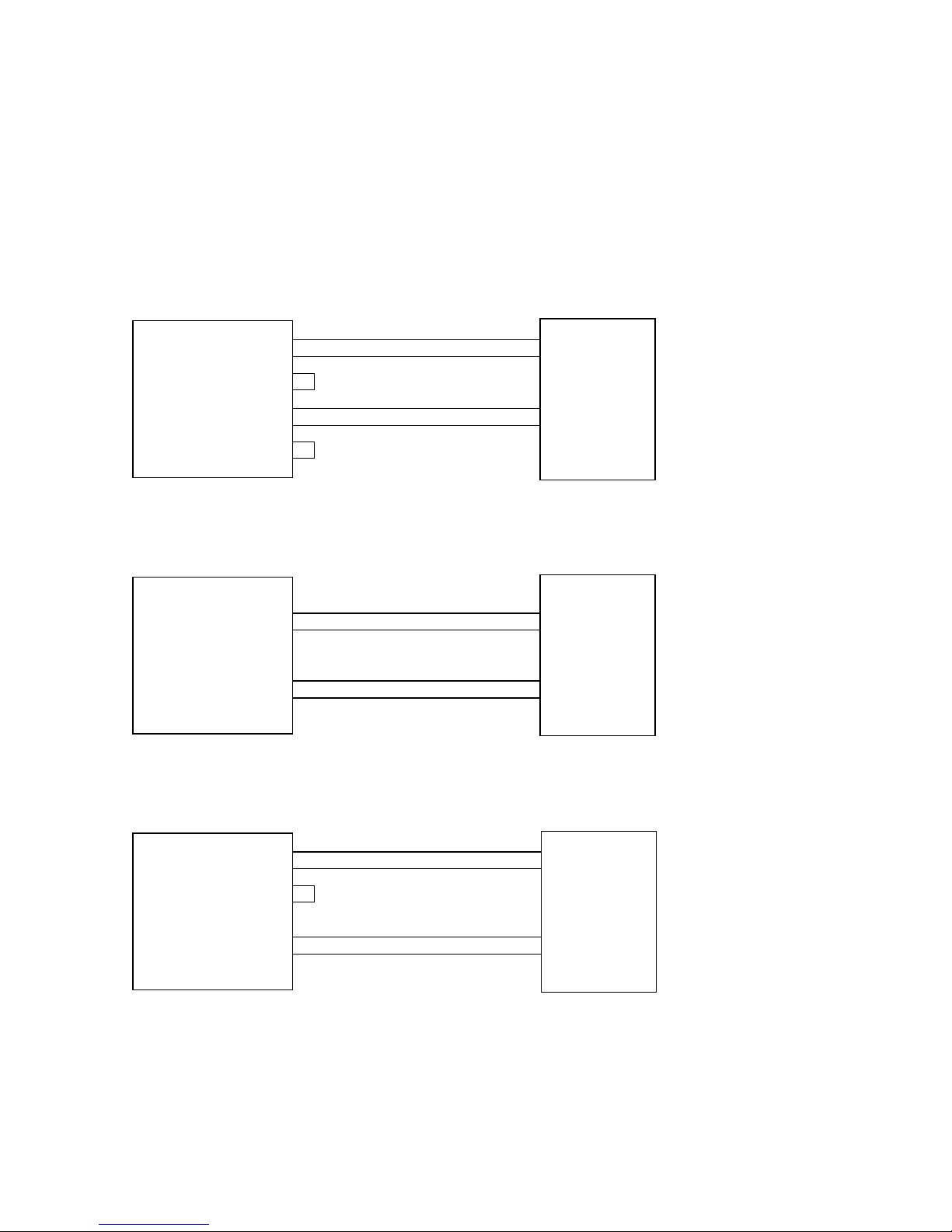
Connection examples
Examples of module switching into active/ passive mode are
shown on the following drawings:
RxD +
RxD -
TxD +
TxD -
active / passive
20mA device
Active Tx and passive Rx current loop application
20mA interface
1
2
3
4
6
7
8
9
Data Out 20mA
Data Out+
Data Out -
Data Out GND
Data In 20mA
Data In+
Data In -
Data In GND
RxD +
RxD -
TxD +
TxD -
active
20mA device
Passive Tx and passive Rx current loop application
20mA interface
1
2
3
4
6
7
8
9
Data Out 20mA
Data Out+
Data Out -
Data Out GND
Data In 20mA
Data In+
Data In -
Data In GND
RxD +
RxD -
TxD +
TxD -
passive
20mA device
Active Tx and active Rx current loop application
20mA interface
Interface module
184xx
1
2
3
4
6
7
8
9
Data Out 20mA
Data Out+
Data Out -
Data Out GND
Data In 20mA
Data In+
Data In -
Data In GND
Interface module
184xx
Interface module
184xx
Page 34

84
W&T
Interface modules
Technical Data
Operating mode: Active and passive mode
Full and halfduplex mode
Baud rate: 0..19.200 Baud
Data format: any
Supported signals: RxD, TxD
ESD immunity: up to 15kV per IEC 801-2,
Level 4 using varistors
Supply voltage: 5V DC ±5%
12V DC (in active mode only)
Supply current: approx. 10mA @ 5V
approx. 50mA @ 12V
TTL connector: 12-pin, 2mm post connector
20mA connector: 9-pin male SUB-D connector
Dimensions: 43 x 31 mm
Weight: approx. 10g
Packing list: 20mA Interface Module
Page 35

85
W&T
Interface modules
Subject to error and alteration
20mA Interface Modules, #184x2
Function
The W&T Interface Modules 18402 and 18412 provide a 20mA
interface for devices equipped with a serial TTL port. The
modules support one data line in each direction and can be
used as an active or passive 20mA component.
In the active mode the module supplies the current required by
the respective 20mA loop, while in the passive mode the loop
current must be supplied by the connected device.
Modules 18402 and 18412 differ only in the arrangement of
the post connector for the serial TTL port, and are in every
other respect functionally identical.
Important installation note
When installing or replacing the Interface Modules, visually
inspect to ensure that the module does not cause a short
circuit with adjacent components. To use the Interface Modules with W&T PC cards, remove the wire jumper between the
SUB-D male connector housing and the module. Otherwise the
galvanic isolation between the interface and the PC may be
defeated.
Supply voltage
The Interface Modules require a supply voltage between 3,3 and
5V DC. The current draw of the modules is approx. 30mA @5V
(20mA @3,3V) in passive mode and 140mA @5V (210mA
@3,3V) in active mode for both current loops.
1
Page 36

86
W&T
Interface modules
Protection against static charges
All external signal lines use ESD-immune interface components
to provide protection against static discharges of up to 15kV
per IEC 801-2, Level 4.
Pin configuration
The 20mA connection for the modules is configured as a
9-pin male SUB-D connector, with the TTL interface formatted
as 12-pin male post connector. Refer to the following
table for connector pin assignments:
TTL interface 20mA interface
Pin 1 of the TTL interface is indicated by a rectangular soldering pad.
Operating modes
A GND level signal on Pin 5 of the SUB-D connector will place
the module in half-duplex mode whereby an echo of the sent
signals is suppressed. The Interface Module can be used as an
active or passive 20mA component. The operating mode can
be selected for both loops seperately.
pin# signal function
1 5V ±5% Vcc
2 RI "low" level
3 RxD output
4 TxD input
5 n.c. n.c.
6 CTS "low" level
7 DTR n.c.
8 DSR "low" level
9 RTS n.c.
10 DCD "low" level
11 12V ±10% n.c.
12 GND signal GND
pin# signal
1 Data Out 20mA
2 Data Out +
3 Data Out -
4 Data Out GND
5 Half Duplex Control
6 Data In 20mA
7 Data In +
8 Data In -
9 Data In GND
Page 37
87
W&T
Interface modules
Subject to error and alteration
Connection examples
Examples of module switching into active/ passive mode are
shown on the following drawings:
RxD +
RxD -
TxD +
TxD -
active / passive
20mA device
Active Tx and passive Rx current loop application
20mA interface
1
2
3
4
6
7
8
9
Data Out 20mA
Data Out+
Data Out -
Data Out GND
Data In 20mA
Data In+
Data In -
Data In GND
RxD +
RxD -
TxD +
TxD -
active
20mA device
Passive Tx and passive Rx current loop application
20mA interface
1
2
3
4
6
7
8
9
Data Out 20mA
Data Out+
Data Out -
Data Out GND
Data In 20mA
Data In+
Data In -
Data In GND
RxD +
RxD -
TxD +
TxD -
passive
20mA device
Active Tx and active Rx current loop application
20mA interface
Interface module
184xx
1
2
3
4
6
7
8
9
Data Out 20mA
Data Out+
Data Out -
Data Out GND
Data In 20mA
Data In+
Data In -
Data In GND
Interface module
184xx
Interface module
184xx
Page 38

88
W&T
Interface modules
Technical Data
Operating mode: Active and passive mode
Full and halfduplex mode
Baud rate: 0..19.200 Baud
Data format: any
Supported signals: RxD, TxD
ESD immunity: up to 15kV per IEC 801-2,
Level 4 using varistors
Supply voltage: 3,3V..5V DC
Min. supply current: in passive mode:
approx. 30mA @5V (20mA @3.3V)
Max. supply current: both loops in active mode:
approx. 140mA @5V (210mA @3,3V)
TTL connector: 12-pin, 2mm post connector
20mA connector: 9-pin male SUB-D connector
Dimensions: 43 x 31 mm
Weight: approx. 10g
Packing list: 20mA Interface Module
Page 39

89
W&T
Interface modules
Subject to error and alteration
POF Interface Modules, #181x1
Function
The W&T Interface Modules 18101 and 18111 provide a
plastic fiber optic interface for devices equipped with a
serial TTL port. The modules support one data line in each
direction and transmit data over a distance of max. 100
meters.
Modules 18101 and 18111 differ only in the arrangement of
the post connector for the serial TTL port, and are in every
other respect functionally identical.
The transmission medium is standard duplex plastic fiber
optic cable, which is inexpensive and extremely easy to work
with and install. The use of fiber optics as a transmission
medium ensures perfect galvanic isolation between the
connected devices and clean transmission even in noise-prone
environments.
Important installation note
When installing or replacing the Interface Modules, visually
inspect to ensure that the module does not cause a short
circuit with adjacent components.
Supply voltage
The Interface Modules require a regulated supply voltage of
5V DC ±5%. The current draw of the modules is approx. 40mA
(typ.).
1
Page 40

90
W&T
Interface modules
Pin configuration
The fiber optic connection for the interface is configured as a
self-locking coupling for duplex plastic fiber optics, with the
TTL interface formatted as 12-pin male post connector. Refer
to the following table for connector pin assignments:
Pin 1 of the TTL interface is indicated by a rectangular soldering pad.
Pin# signal funktion
1 5V ±5% Vcc
2 RI n.c.
3 RxD output
4 TxD input
5 n.c. n.c.
6 CTS connected to RTS
7 DTR connected to DSR
8 DSR connected to DTR
9 RTS connected to CTS
10 DCD n.c.
11 +12V ±10% n.c.
12 GND signal GND
TTL interface
Module diagram
locking levers
transmit line
receive line
16
712
Page 41

91
W&T
Interface modules
Subject to error and alteration
Assembly
Connecting the plastic fiber optic cable to the interface
requires no special tools:
• Trim the fiber optic cable to the desired length using a
sharp knife. Make your cut as close to a right angle to the
longitudinal axis of the cable as possible. A simple cut is
generally sufficient, with no reworking required.
• Separate the individual duplex conductors back from the
cut point to a distance of around 2cm.
• Pull the locking levers on the fiber optic female connector
back towards the module along the upper side of the
coupling.
• At the same time insert the separated end of the fiber
optic duplex line into the fiber optic coupling female.
• Releasing the locking levers locks the fiber optics into the
coupling.
• To release, pull the two locking levers on the top of the
coupling towards the module, and pull the fiber optic
cable out of the female.
The arrows on the top side of the coupling clearly show the
location of the emitter and receiver lines.
Please note that when connecting two fiber optic components,
the emitter of the first must always be connected to the
receiver channel of the second component. A visible red light
beam is always sent along with data, so that the sending line
can always be easily identified.
Page 42

92
W&T
Interface modules
Technical Data
Baud rate: 0..115.200 Baud
Data format: any
Supported signals: RxD, TxD
Max. distance: 100m
Supply voltage: 5V DC ±5%
Supply current: approx. 40mA
TTL connector: 12-pin, 2mm post connector
POF connector: Integrated socket
with automatic interlocking
of the fiber-optic cable
POF medium: Duplex plastic optical fiber cable
2.2 x 4.4 mm, fiber diameter of
980µm, core: PMMA, cladding: PE
Dimensions: 43 x 31 mm
Weight: approx. 10g
Packing list: POF Interface Module
Page 43

93
W&T
Interface modules
Subject to error and alteration
Fiber Optic Interface Modules, #1812x
Function
The W&T Interface Modules 18120 and 18121 provide a
fiber optic interface with ST connectors for devices equipped
with a serial TTL port. Modules 18120 and 18121 differ only in
the arrangement of the post connector for the serial TTL port,
and are in every other respect functionally identical.
The light used for data transmission has a wavelength of 820
nm. Commonly available Multimode duplex glass fiber optic
cable in 50/125µm or 62.5/125µm is used as the transmission
medium, which due to its wide application in networking is
easily available and cost-effective. This means that even
already existing glass fiber optic lines intended for use in
networks can easily be used for transmitting serial data.
Depending on the attenuation of the glass fiber optic cable
used, data can be transmitted over a distance of maximum
3800 meters.
Important installation note
When installing or replacing the Interface Modules, visually
inspect to ensure that the module does not cause a short
circuit with adjacent components.
Supply voltage
The Interface Modules require a regulated supply voltage of
5V DC ±5%. The current draw of the modules is approx. 60mA
(typ.).
1
Page 44

94
W&T
Interface modules
Pin configuration
The fiber optic connection for the modules is configured as a
ST connector, with the TTL interface formatted as 12-pin male
post connector. Refer to the following table for connector pin
assignments:
Pin 1 of the TTL interface is indicated by a rectangular soldering pad.
Module diagram
16
712
Fiber optic RxD
Fiber optic TxD
Pin# signal funktion
1 5V ±5% Vcc
2 RI n.c.
3 RxD output
4 TxD input
5 n.c. n.c.
6 CTS connected to RTS
7 DTR connected to DSR
8 DSR connected to DTR
9 RTS connected to CTS
10 DCD n.c.
11 +12V ±10% n.c.
12 GND signal GND
TTL interface
Page 45

95
W&T
Interface modules
Subject to error and alteration
Technical Data
Baud rate: 0..1,5 MBaud
Data format: any
Supported signals: RxD, TxD
Fiber-optic medium: Duplex multimode fiber-optic cable
Max. distance: 50/125µm:
typ. 3200m, min. 1400m @3dB/km
62.5/125µm:
typ. 3800m, min. 2200m @3.5dB/km
200um PCS fiber:
typ. 2500m, min. 1500m @8dB/km
Optical budget: 50/125µm:
typically 9.6dB, min. 4.2dB
62.5/125µm:
typically 13.4dB, min. 8.0dB
200um PCS fiber:
typically 20dB, min. 12dB
Supply voltage: 5V DC ±5%
Supply current: approx. 60mA
TTL connector: 12-pin, 2mm post connector
FO cable connector: ST plug adapter
SMA plug adapter on request
Dimensions: 55 x 31 mm
Weight: approx. 10g
Packing list: Fiber Optic Interface Module
Page 46

96
W&T
Interface modules
Page 47

97
W&T
Interface modules
Subject to error and alteration
Interface Module USB, #18311
Function
The W&T Interface Module18311 equips devices having a
serial TTL interface with a USB slave interface.
The module uses an integrated serial EEPROM for
non-volatile storage of Vendor ID, Product ID, Serial Number
and a product description. The EEPROM is programmable
on-board via USB.
Current drivers for all supported Windows versions are
available via the Internet on the module data sheet page.
Supply voltage
The USB interface module requires a regulated DC voltage of
5V DC ±5% at typ. 30 mA.
Important installation notes
When installing or replacing the Interface Modules you must
visual inspect to be sure that the module is not causing any
short circuit to adjacent components.
1
Page 48

98
W&T
Interface modules
Wiring configuration
The USB connection on the module is implemented as a USB
female of type „B“, and the TTL interface on the module as a
12-pole header connector. The connector pin configuration is
shown in the following table.
Pin 1 of the TTL interface is indicated by a square solder eye.
Module drawing:
USB
Typ B
16
712
pin# signal function
1 5V ±5% Vcc
2 RI input
3 TxD output
4 RxD input
5 n.c. n.c.
6 DTR output
7 CTS input
8 DSR input
9 RTS output
10 DCD input
11 12V ±10% n.c.
12 GND signal GND
Page 49

99
W&T
Interface modules
Subject to error and alteration
Technical Data
Baud rate: 300 baud..3 MBaud
adjustable baud rates =
3 MBaud/n, with n = 1..16383
Data bits: 7 or 8
Stop bits: 1 or 2
Parity: no, even, odd, mark space
Supported signals: RxD, TxD, RTS, CTS,
DSR, DCD, DTR, RI
Integrated memory: 384-byte receive buffer
128- byte send buffer
Supply voltage: 5V DC ±5%
Quiescent current: approx. 25 mA
TTL connection: 12-pole 2mm header
USB connection: USB female, Type B
Dimensions: 55 x 31 mm
Weight: approx. 10g
Scope of delivery: USB Interface Module
Page 50

100
W&T
Interface modules
 Loading...