

Page 1
Manual
Digital I/O Extender Sets
Type 17633
17634, 17635
Release 1.3
W&T
Page 2

30
W&T Digital-I/O Extender Sets
© 05/2015 by Wiesemann & Theis GmbH
Subject to error and alteration:
Since it is possible that we make mistakes, you mustn’t use
any of our statements without verification. Please, inform us
of any error or misunderstanding you come about, so we can
identify and eliminate it as soon as possible.
Carry out your work on or with W&T products only to the
extent that they are described here and after you have
completely read and understood the manual or guide. We
are not liable for unauthorized repairs or tampering. When in
doubt, check first with us or with your dealer.
Page 3

31
W&T Digital-I/O Extender Sets
Irrtum und Änderung vorbehalten
Although the low bandwidth and large voltage swing of
digital I/O signals make them essentially less sensitive to
external noise than for example serial data signals, in some
case the operating conditions necessitate transmission
procedures which are completely resistant to noise effects
along the transmission line.
Glass fibers used as a transmission medium meet these
requirements ideally while also offering the advantage of
galvanic isolation up to virtually any level between the
connected devices. In installations which are subject to
the risk of severe weather conditions, such as in outdoor
locations or between distant buildings, such a solution
ensures a permanently reliable connection even under adverse
conditions.
Wiesemann & Theis offers a whole family of various glass
fiber interfaces which allow conversion of standard interfaces
into an optical interface for connecting glass fiber cable.
The W&T Digital-I/O Extender Sets, which carry the digital
I/O signals over glass fiber optic cable using a multiplexing
procedure, are described on the following pages along with
the technical data and connection examples.
Up-to-date information about new product developments
can be found in the Internet at http://www.wut.de or in the
e-mail updates from the W&T Interface Club, which you can
sign up for on the W&T homepage.
Page 4

32
W&T Digital-I/O Extender Sets
Table of Contents
Digital-I/O Extender Set 2x2, MM ST, Model 17633 .... 33
Function .............................................................................33
Power Supply and Galvanic Isolation ...................................33
Housing ..............................................................................34
Glass Fiber Interface and Digital-I/O Port ............................34
Terminal Assignments ........................................................35
Supply Voltage Input ...........................................................35
Digital Inputs ......................................................................36
Digital Outputs ...................................................................37
Cable break behavior ..........................................................38
Technical Data ....................................................................39
Digital-I/O Extender Set 8x8, MM ST, Model 17634 .... 41
Function .............................................................................41
System security ...................................................................41
Power Supply and Galvanic Isolation ...................................42
Housing ..............................................................................42
Glass Fiber Interface and Digital-I/O Port ............................43
LEDs and terminations ........................................................44
Supply Voltage Input ...........................................................44
Digital Inputs ......................................................................45
Digital Outputs ...................................................................46
Cable break response .........................................................47
Technical Data ....................................................................48
Digital-I/O Extender Set 8x8, SM SC, Model 17635 ..... 49
Function .............................................................................49
System security ...................................................................49
Power Supply and Galvanic Isolation ...................................50
Housing ..............................................................................50
Glass Fiber Interface and Digital-I/O Port ............................51
LEDs and terminations ........................................................52
Supply Voltage Input ...........................................................52
Digital Inputs ......................................................................53
Digital Outputs ...................................................................54
Cable break response .........................................................54
Technical Data ....................................................................55
Page 5

33
W&T Digital-I/O Extender Sets
Subject to error and alteration
Digital-I/O Extender Set, Model 17633
Function
The W&T Digital-I/O Extender Set, Model 17633 enables
sending of digital I/O signals bi-directionally over a glass
fiber optic cable.
The set consists of two digital-I/O <> glass fiber optic
converters and supports two I/O channels in each direction.
A special communications protocol between the converters is
used for transmitting over the glass fiber optic cable, so that
the converters can only be used in pairs.
Power Supply
The signal converters are powered by an integrated switched
regulator. This regulator has a variable input voltage range
and enables powering of the converters by using any DC or
AC voltage between 12 and 24 volts. The supply voltage is
reverse polarity protected and can be implemented on the
underside of the converters using the included plug-in 2-pole
screw terminal.
Galvanic Isolation
Within the signal converters the I/O connections are
galvanically isolated from the supply voltage up to min. 1000
V using a DC/DC converter. The level of galvanic isolation
between the two converters and thereby between the I/O
terminal points is determined primarily by the length of the
glass fiber optic cable used.
Page 6

34
W&T Digital-I/O Extender Sets
Housing
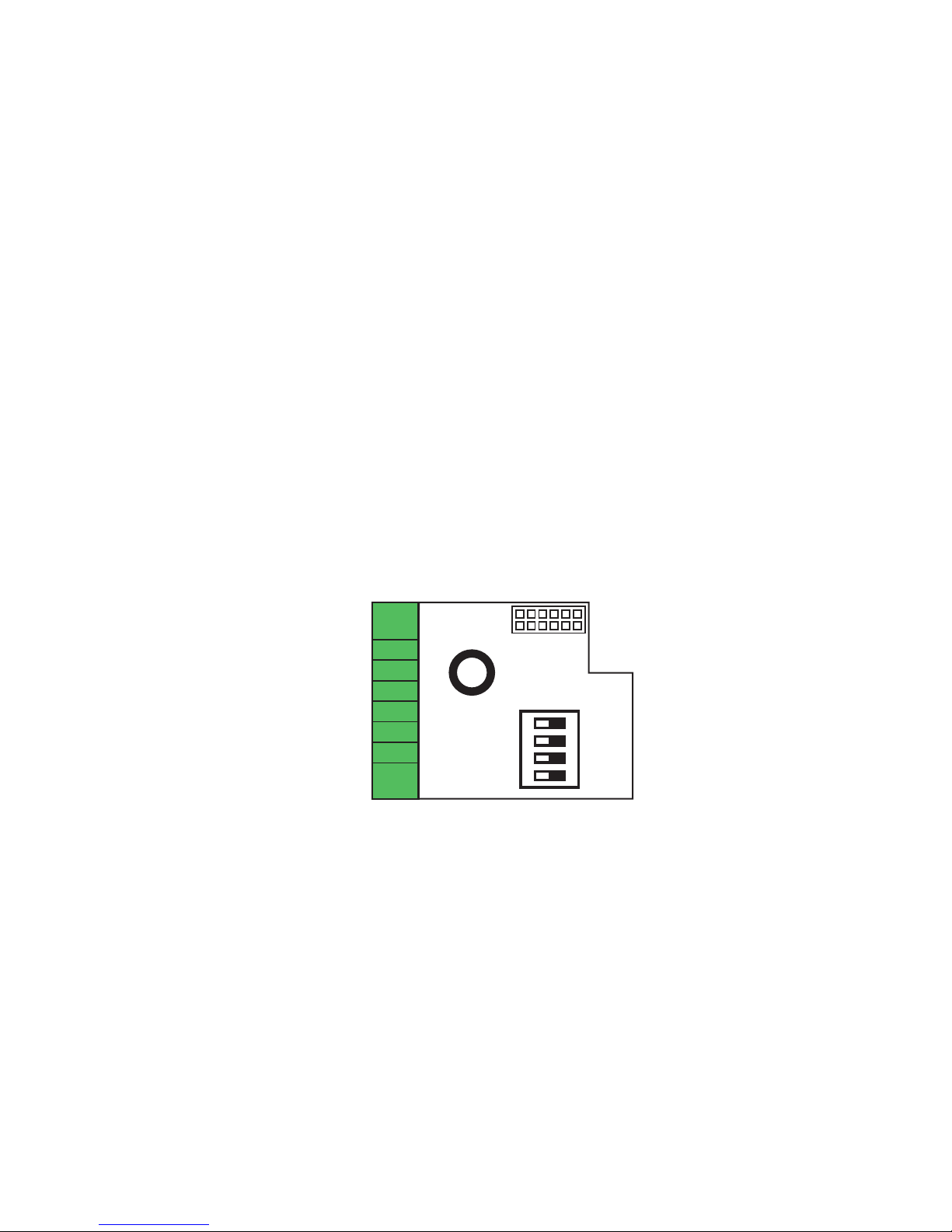
The Digital-I/O <> glass fiber optic are integrated inside
a housing for mounting on DIN rails. To configure the
cable break behavior you must open the Interface housing so
that the DIL switches on the Digital-I/O Interface Module are
accessible. To do this, slide the housing cover with the
attached circuit board out of the housing body by grabbing
the ST connector.
Glass Fiber Interface
Common ST connectors are used for connecting the glass
fiber optic cable. A version with SMA connectors is also
available as a special on request.
The light used for data transmission has a wavelength of
820 nm. Common 50/125 µm or 62,5/125 µm multimode
duplex glass fiber optic cable is used, which thanks to its
wide use in networking is easily available and inexpensive.
This means that even existing glass fiber optic sections which
are intended for use in networks can be used for sending
digital signals. Depending on the attenuation factor of the
glass fiber optic cable used, data transmission over distances
of up to 3800 meters is possible.
Digital-I/O Port
The Digital-I/O Port is configured as a plug-in 3.5mm
terminal block so that the connected in- and outputs can be
disconnected from the signal converter at any time without
having to unscrew anything.
All digital inputs use overvoltage-rated components to protect
against transients which exceed the permissible input voltage
of the inputs.
Page 7
35
W&T Digital-I/O Extender Sets
Subject to error and alteration
Driver chips are used for the digital outputs which provide
integrated protection against short circuit, overload and
thermal destruction.
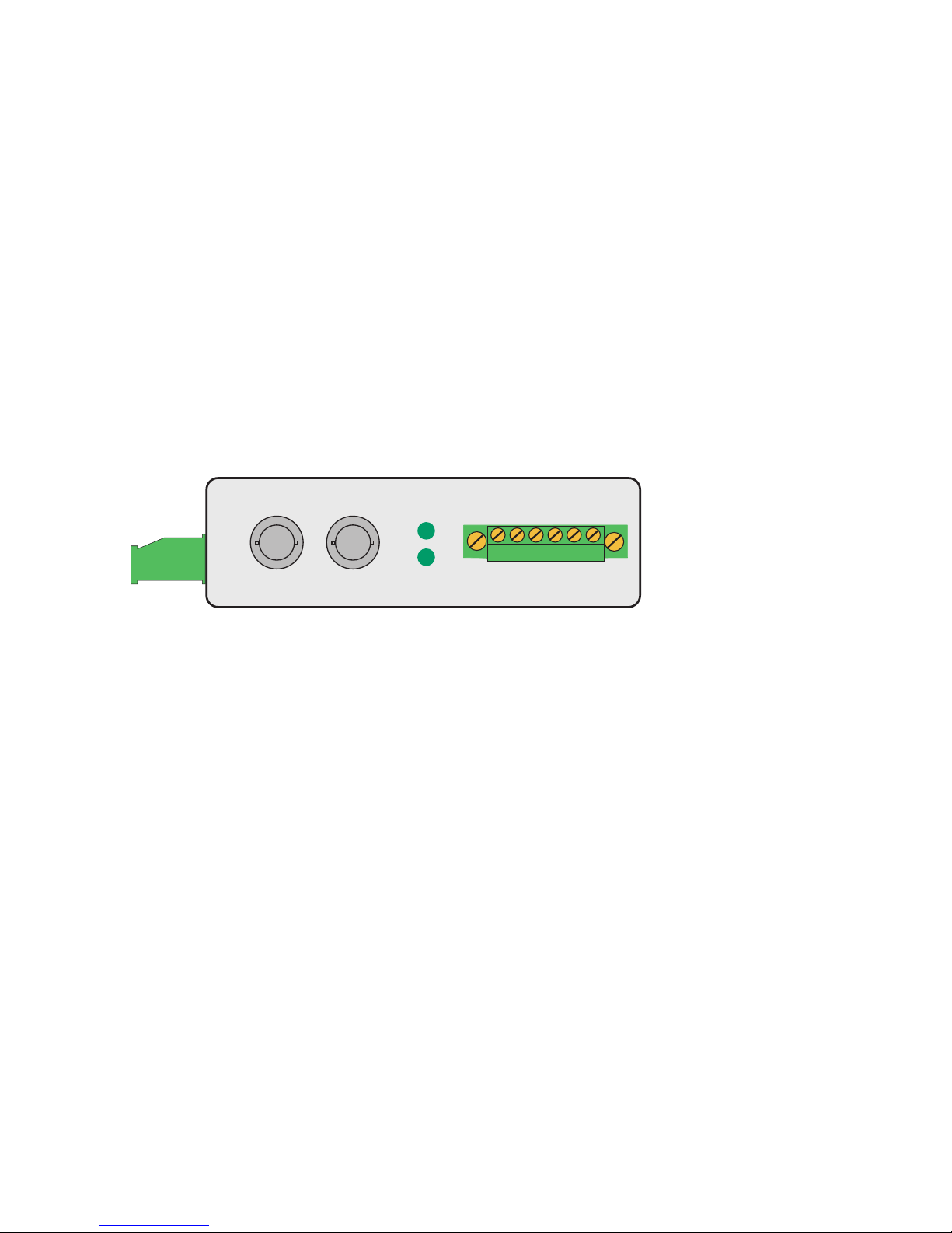
LEDs and Terminal Assignments
The converter features two LED’s, with the Power LED indicating correct supply voltage. The Data LED is not connected.
The configuration of the signal and supply terminals and
the pin configuration of the interfaces can be found on the
device label as well as in the following illustration:
I/O Port
Power
Data
TxD RxD
Fiber Optic Port
Outputs Vdd GND Inputs
1 2 + - 1 2
Vcc
AC/DC
Supply Voltage Input
The supply voltage is connected to the screw terminals on the
underside of the housing.
Any desired voltage of 12V to 24V can be used for power.
Since the signal converters can be operated with DC or AC
voltage, no special precautions are necessary with respect to
the polarity of the supply voltage.
The Vdd terminal on the front side supplies only the
switching outputs and must be connected to a DC voltage.
1
Page 8
36
W&T Digital-I/O Extender Sets
Digital Inputs
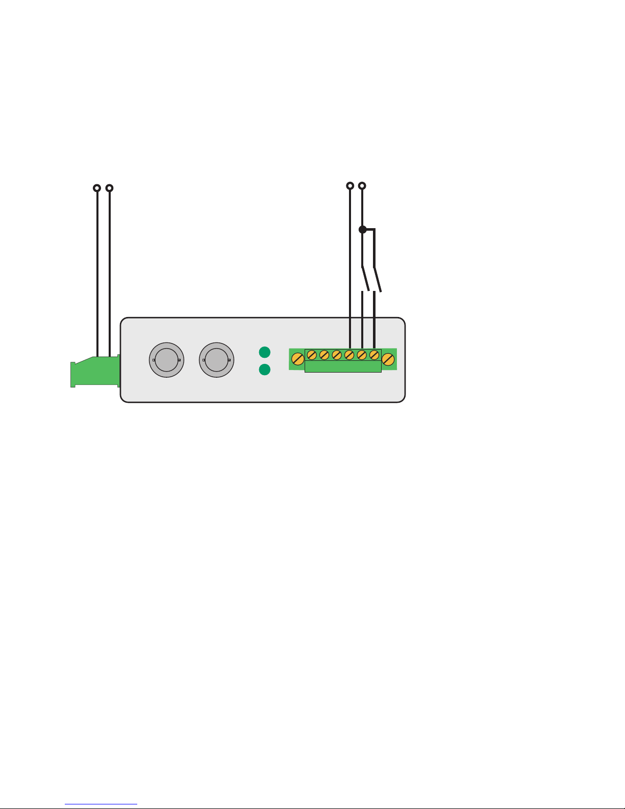
The basic wiring of the inputs for the Digital-IO Extender Set
can be seen in the following illustration:
The digital inputs of the Digital-I/O Extender Set 17633 are
„Type 3“ according to IEC 61131-2 and have a maximum input
voltage of 30V with respect to the device reference ground.
The lines to the digital inputs should not be longer than
necessary.
I/O Port
Power
Data
TxD RxD
Fiber Optic Port
Outputs Vdd GND Inputs
1 2 + - 1 2
Vcc
AC/DC
max. 30V DC
+
-
12..24V AC/DC
Page 9
37
W&T Digital-I/O Extender Sets
Subject to error and alteration
Digital Outputs
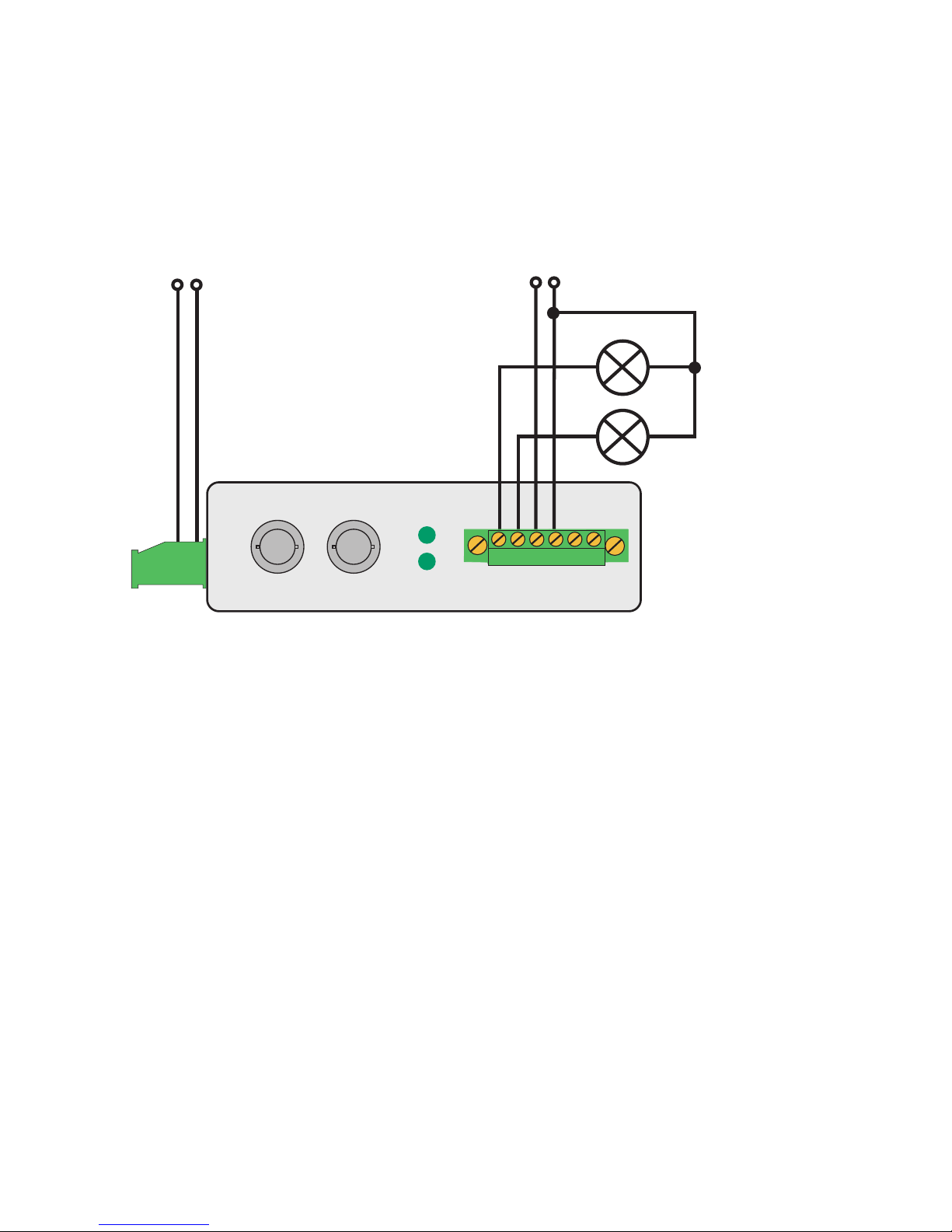
The basic wiring of the switching outputs for the Digital-IO
Extender Set can be seen in the following illustration:
The two digital outputs of the Digital-I/O Extenders are
current sourcing. The supply voltage for the outputs may be
between +6 V and +30 V DC and is provided at terminals Vdd
and GND.
Each of the outputs can switch a maximum current of 0.5A.
If loads with an inductive component (e.g. relays, contactors,
solenoids etc.) need to be switched, the outputs must be
additionally protected using recovery diodes.
The outputs have thermal overload protection and are short
circuit protected. In the OFF state a very low current of
approx. 10µA is used to check whether the outputs are
switched to a load. If LEDs are connected to the outputs, this
can result in a slight glow even in the rest state.
I/O Port
Power
Data
TxD RxD
Fiber Optic Port
Outputs Vdd GND Inputs
1 2 + - 1 2
Vcc
AC/DC
+
-
12..24V AC/DC
6.. 30V DC
Page 10
38
W&T Digital-I/O Extender Sets
When sizing the output voltage supply, the required current
must always be taken into consideration. If the selected
voltage for supplying the loads varies between 12V and
24V DC, the signal converter and the switched loads can be
supplied from the same source.
Cable break behavior
Should the glass fiber connection be interrupted or if the
glass fiber cable is not connected, the default response is for
all digital outputs to go directly to the Off state. A different
response can be configured individually for each channel
using DIL switches inside the unit. Simply set the DIL switches
for the corresponding in- and outputs in both Digital-I/O <>
Glass Fiber converters to ON. The names of the DIL switches
In1, In2, Out1 and Out2 can be found on the circuit board
near the switch.
To change for example the
cable break behavior of the
first I/O channel, set DIL
switch In1 on the first interface AND DIL switch Out1
on the second interface to
ON. Now when there is a
cable break or the glass
fiber cable is dis connected,
the output goes directly to
the ON state.
In this way each of the four channels can be configured
individually as desired.
Note: Changing the setting of a DIL switch on only one
Interface causes the signal to be sent inverted. When
voltage is present on the input the corresponding
output is turned off.
1
Page 11

39
W&T Digital-I/O Extender Sets
Subject to error and alteration
Technical Data
Transmitted signals: 2x Digital In, 2x Digital Out
Digital-I/O connector: 6-pin plug-in screw terminal
Digital outputs: 2 outputs, 6V-30V, 0.5A,
Short circuit protected
Digital inputs: 2 inputs acc. to IEC61131-2, type 3
Input voltage: max. 30V
Signal delay: Input to output: max. 250µs
Glass fiber connector: ST connectors (SMA on request)
Fiber medium: Duplex multimode glass fiber cable
Transmitter type: LED
Wavelength: 820 nm
Optical budget: 50/125µm: typ. 9.6dB, min. 4,2dB
62.5/125µm: typ. 13.4dB, min. 8.0dB
Maximum distance: 50/125µm:
typ. 3200m, min. 1400m @3dB/km
62.5/125µm:
typ. 3800m, min. 2200m @3.5dB/km
Supply voltage: 12..24 V AC/DC
Current draw: max. 150 mA at 12 V DC
Isolation: min. 1 KV between digital-I/O
and supply voltage
Temperature range: Storage: -40..+70°C
Operating: 0..+60°C
Humidity range: 5..90% rH (non condensing)
Life expectancy: > 25 years (@25°C ambient temp.)
Housing: Plastic housing for DIN rail mount
Dimensions: 105x75x22,5 mm
Weight: approx. 250 g
Scope of delivery: 1x Digital-I/O Extender Set 2x2
Multimode ST
Page 12

40
W&T Digital-I/O Extender Sets
Page 13

41
W&T Digital-I/O Extender Sets
Subject to error and alteration
Digital-I/O Extender Set 8x8, Model 17634
Function
The W&T Digital-I/O Extender Set 8x8, Model 17634 enables
sending of up to 16 digital I/O signals over a glass fiber optic
cable.
The set consists of two digital-I/O <> glass fiber optic
converters and supports eight I/O channels in each direction.
A special safety communications protocol between the
converters is used for transmitting over the glass fiber optic
cable, so that the converters can only be used in pairs.
System security
The W&T Digital-I/O Extender Set 8x8 is a full hardware
implementation, so that the risk of a malfunction caused by
hidden firmware errors or a system crash is precluded.
The functionality of the glass fiber optic connection is
cycli cally monitored. The status of the connection is indicated
by an LED and by a signal on a switching output.
In addition, the default status of the digital outputs should
the fiber optic line fail can be individually configured for each
output.
Page 14

42
W&T Digital-I/O Extender Sets
Power Supply
The converters have a common power supply for the interface
electronics and the digital outputs. The electronics is supplied
by an integrated switching regulator with a wide-range input,
so that the device can be operated at any desired voltage
between 8 and 30V DC. AC powering is not possible. The
supply voltage is brought to the front-mounted 6-pin plug-in
panel connector on terminals Vdd and GND.
Galvanic isolation
The amount of galvanic isolation between the two converters
and thereby between the I/O end points is determined solely
by the length of the fiber optic cable and the interface supply
voltage.
Housing and arrangement of the operating elements
The W&T Digital-I/O <> Fiber Optic Converters are housed
in a 45mm wide plastic enclosure for mounting on DIN rails.
All connectors and LEDs are located on the front panel of
the units so that they are accessible when installed. The DIL
switches for configuring the default state upon cable break is
located on the top of the unit and can be set without opening
the housing.
1
Page 15

43
W&T Digital-I/O Extender Sets
Subject to error and alteration
Glass Fiber Interface
Common ST connectors are used for connecting the glass
fiber optic cable. A version with SMA connectors is also
available as a special on request.
The light used for data transmission has a wavelength of
820 nm. Common 50/125 µm or 62,5/125 µm multimode
duplex glass fiber optic cable is used, which thanks to its
wide use in networking is easily available and inexpensive.
This means that even existing glass fiber optic sections which
are intended for use in networks can be used for sending
digital signals. Depending on the attenuation factor of the
glass fiber optic cable used, data transmission over distances
of up to 3800 meters is possible.
Digital-I/O Port
The Digital-I/O-Port is configured as a plug-in 3.5mm
terminal block so that the connected in- and outputs can be
disconnected from the signal converter at any time without
having to unscrew anything.
All digital inputs use overvoltage-rated components to protect
against transients which exceed the permissible input voltage
of the inputs.
Driver chips are used for the digital outputs which provide
integrated protection against short circuit, overload and
thermal destruction.
Page 16
44
W&T Digital-I/O Extender Sets
LEDs and terminations
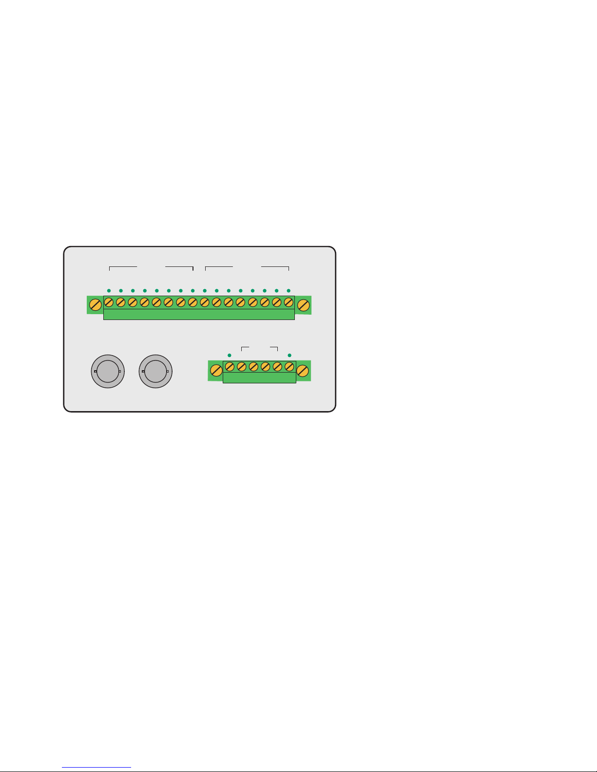
The Converter has 16 LEDs for displaying the respective I/O
status, a Power LED which indicates correct supply voltage to
the device, and a Link LED for indicating errorless function of
the fiber optic connection.
The configuration of the signal and power connectors and
interface wiring can be found on the label and in the following
illustration:
Input supply voltage
The DC supply voltage is connected to Vdd (+) and GND (-)
on the 6-pin terminal on the front panel. Vdd supplies the
interface electronics as well as the digital switching outputs.
Any DC voltage between 8V and 30V may be used.
Take care not to reverse the polarity of the supply
voltage or to use AC voltage!
1
Fiber Optic Port
Link VddGND
TxDRxD
0 12345670 1234567
Outputs
Inputs
Page 17
45
W&T Digital-I/O Extender Sets
Subject to error and alteration
Digital Inputs
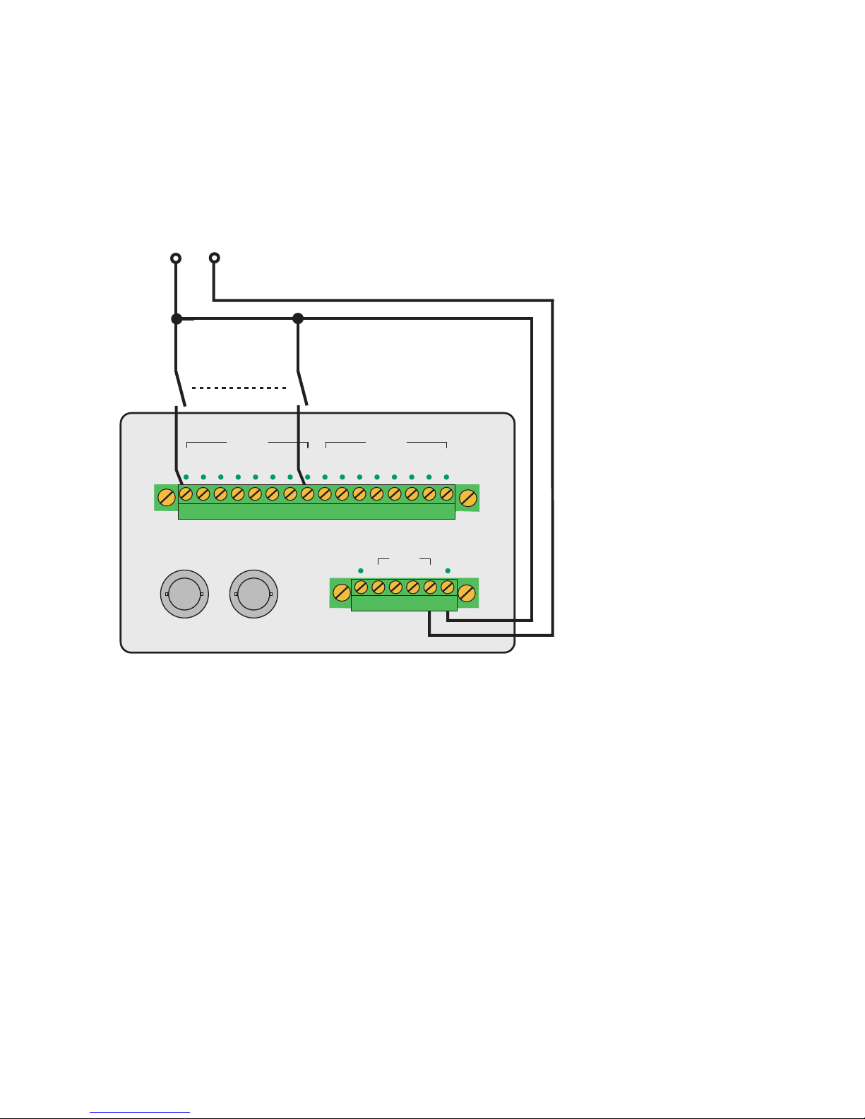
The basic wiring of the inputs for the Digital-IO Extender Set
can be seen in the following illustration:
The digital inputs of the Digital-I/O Extender Set 17634 are
„Type 3“ according to IEC 61131-2 and have a maximum input
voltage of 30V with respect to the device reference ground.
The lines to the digital inputs should not be longer than
necessary.
12..24V DC
+
-
Fiber Optic Port
Link VddGND
TxDRxD
0123456701234567
Outputs
Inputs
Page 18
46
W&T Digital-I/O Extender Sets
Digital Outputs
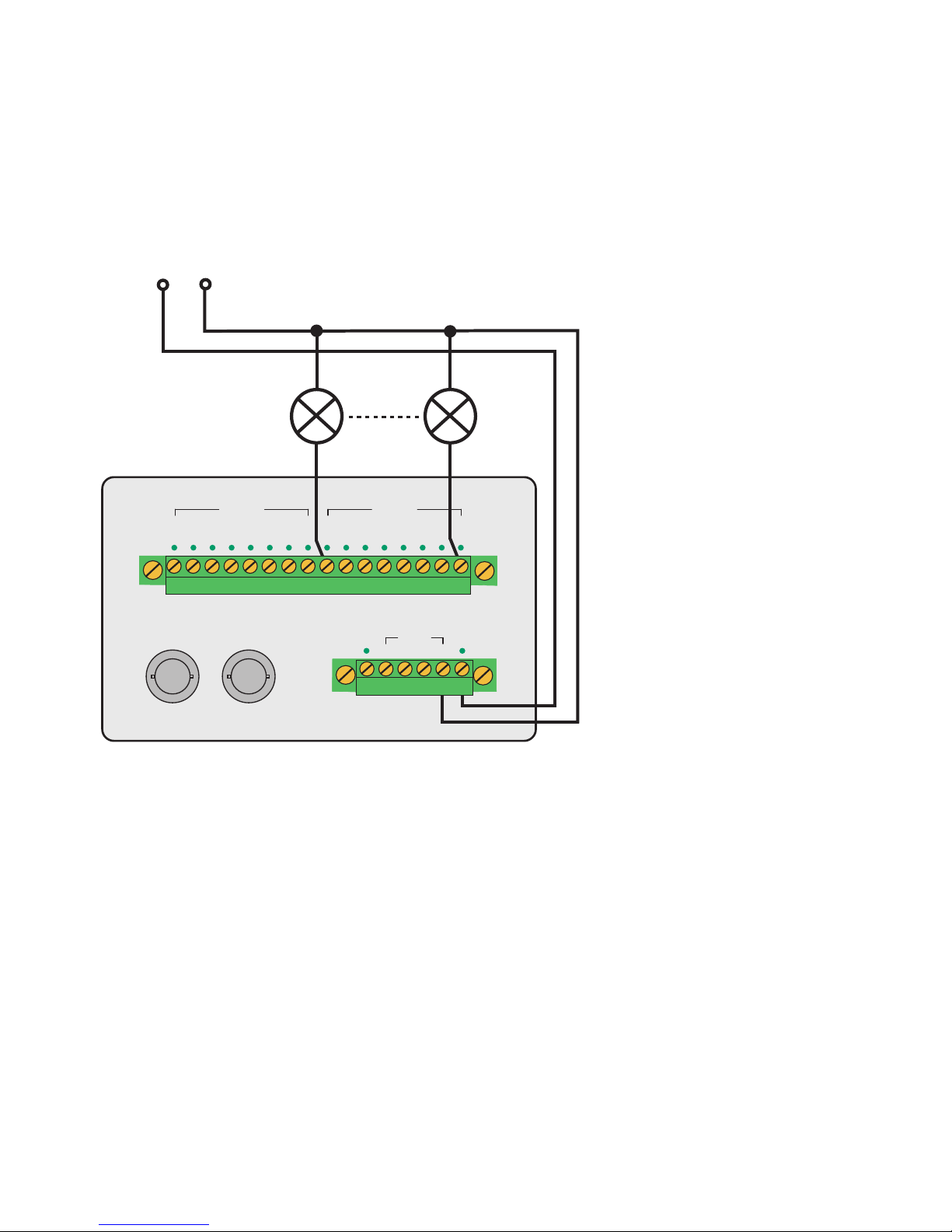
The basic wiring of the switching outputs for the Digital-IO
Extender Set can be seen in the following illustration:
The digital outputs of the Digital-I/O Extender Sets are current
sourcing and apply the voltage brought to Vdd to the output
terminals. Each of the outputs can switch a maximum current
of 0.5A. If loads with an inductive component (e.g. relays,
contactors, solenoids etc.) need to be switched, the outputs
must be additionally protected using recovery diodes.
The outputs have thermal overload protection and are short
circuit protected. In the OFF state a very low current of
approx. 10µA is used to check whether the outputs are
switched to a load. If LEDs are connected to the outputs, this
can result in a slight glow even in the rest state.
1
Fiber Optic Port
Link VddGND
TxDRxD
12..24V DC
+
-
0 123456701234567
Outputs
Inputs
Page 19

47
W&T Digital-I/O Extender Sets
Subject to error and alteration
Cable break response
The functionality of the glass fiber optic connection is
cycli cally monitored by a special safety communications
protocol. The status of the connection is indicated by the Link
LED and by a signal on the Link switching output.
An 8x DIL switch is provided on the top side of the unit for
configuring the cable break response, whereby the status of
the outputs when the fiber optic connection is interrupted
can be set for each individual output. The arrangement of the
DIL switches and output can be found on the label on the top
side of the unit.
The factory default setting is for all switches in the Off
position. If this setting is not changed, all the digital outputs
on the unit will turn off when the fiber optic connection is
interrupted.
This response can be inverted by setting the DIL switch
associated with an output to ON. This setting can be made
individually for each of the eight outputs.
Page 20

48
W&T Digital-I/O Extender Sets
Technical Data
Transmitted signals: 8x Digital In, 8x Digital Out
Digital-I/O connector: 16-pin plug-in screw terminal
Digital outputs: 8 outputs, 6V-30V, 0.5A,
Short circuit protected
Digital inputs: 8 inputs acc. to IEC61131-2, type 3
Input voltage: max. 30V
Signal delay: Input to output: max. 20ms
Glass fiber connector: ST connectors (SMA on request)
Fiber medium: Duplex multimode glass fiber cable
Transmitter type: LED
Wavelength: 820 nm
Optical budget: 50/125µm: typ. 9.6dB, min. 4,2dB
62.5/125µm: typ. 13.4dB, min. 8.0dB
Maximum distance: 50/125µm:
typ. 3200m, min. 1400m @3dB/km
62.5/125µm:
typ. 3800m, min. 2200m @3.5dB/km
Supply voltage: 8..30V DC
Current draw: typ. 20 mA at 12V DC
Temperature range: Storage: -40..+70°C
Operating: 0..+70°C
Humidity range: 5..90% rH (non condensing)
Life expectancy: > 25 years (@25°C ambient temp.)
Housing: Plastic housing for DIN rail mount
Dimensions: 105x75x45mm
Weight: approx. 300 g
Scope of delivery: 1x Digital-I/O Extender Set 8x8
Multimode ST
Page 21

49
W&T Digital-I/O Extender Sets
Subject to error and alteration
Digital-I/O Extender Set 8x8, Model 17635
Function
The W&T Digital-I/O Extender Set 8x8, Model 17635 enables
sending of up to 16 digital I/O signals over a singlemode
glass fiber optic cable.
The set consists of two digital-I/O <> glass fiber optic
converters and supports eight I/O channels in each direction.
A special safety communications protocol between the
converters is used for transmitting over the glass fiber optic
cable, so that the converters can only be used in pairs.
System security
The W&T Digital-I/O Extender Set 8x8 is a full hardware
implementation, so that the risk of a malfunction caused by
hidden firmware errors or a system crash is precluded.
The functionality of the glass fiber optic connection is
cycli cally monitored. The status of the connection is indicated
by an LED and by a signal on a switching output. In addition,
the default status of the digital outputs should the fiber optic
line fail can be individually configured for each output.
Page 22

50
W&T Digital-I/O Extender Sets
Power Supply
The converters have a common power supply for the interface
electronics and the digital outputs. The electronics is supplied
by an integrated switching regulator with a wide-range input,
so that the device can be operated at any desired voltage
between 8 and 30V DC. AC powering is not possible. The
supply voltage is brought to the front-mounted 6-pin plug-in
panel connector on terminals Vdd and GND.
Galvanic isolation
The amount of galvanic isolation between the two converters
and thereby between the I/O end points is determined solely
by the length of the fiber optic cable and the interface supply
voltage.
Housing and arrangement of the operating elements
The W&T Digital-I/O <> Fiber Optic Converters are housed
in a 45mm wide plastic enclosure for mounting on DIN rails.
All connectors and LEDs are located on the front panel of
the units so that they are accessible when installed. The DIL
switches for configuring the default state upon cable break is
located on the top of the unit and can be set without opening
the housing.
1
Page 23

51
W&T Digital-I/O Extender Sets
Subject to error and alteration
Glass Fiber Interface
Common SC connectors are used for connecting the
singlemode glass fiber optic cable.
The light used for data transmission has a wavelength of
1310 nm. Common 9/125 µm singlemode duplex glass fiber
optic cable is used, which thanks to its wide use in networking is easily available and inexpensive. This means that
even existing glass fiber optic sections which are intended
for use in networks can be used for sending digital signals.
Depending on the attenuation factor of the glass fiber optic
cable used, data transmission over distances of up to 20 km
is possible.
Digital-I/O Port
The Digital-I/O-Port is configured as a plug-in 3.5mm
terminal block so that the connected in- and outputs can be
disconnected from the signal converter at any time without
having to unscrew anything.
All digital inputs use overvoltage-rated components to protect
against transients which exceed the permissible input voltage
of the inputs.
Driver chips are used for the digital outputs which provide
integrated protection against short circuit, overload and
thermal destruction.
1
Page 24
52
W&T Digital-I/O Extender Sets
LEDs and terminations
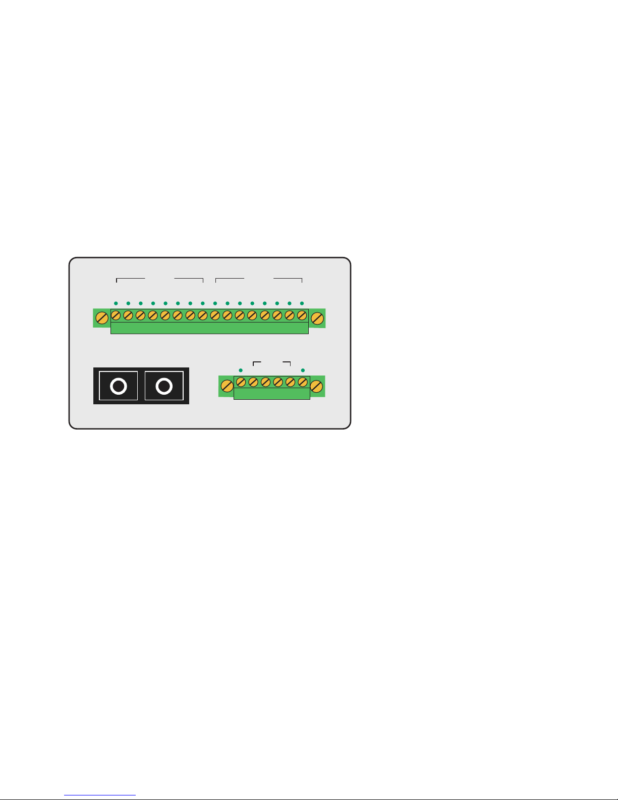
The Converter has 16 LEDs for displaying the respective I/O
status, a Power LED which indicates correct supply voltage to
the device, and a Link LED for indicating errorless function of
the fiber optic connection.
The configuration of the signal and power connectors and
interface wiring can be found on the label and in the following
illustration:
Input supply voltage
The DC supply voltage is connected to Vdd (+) and GND (-) on
the 6-pin terminal on the front panel. Vdd supplies the interface electronics as well as the digital switching outputs. Any
DC voltage between 8V and 30V may be used.
Take care not to reverse the polarity of the supply
voltage or to use AC voltage!
1
Link VddGND
0 1 2 3 4 5 6 70 1 2 3 4 5 6 7
Outputs
Inputs
TxD RxD
Fiber Optic SC
Page 25
53
W&T Digital-I/O Extender Sets
Subject to error and alteration
Digital Inputs
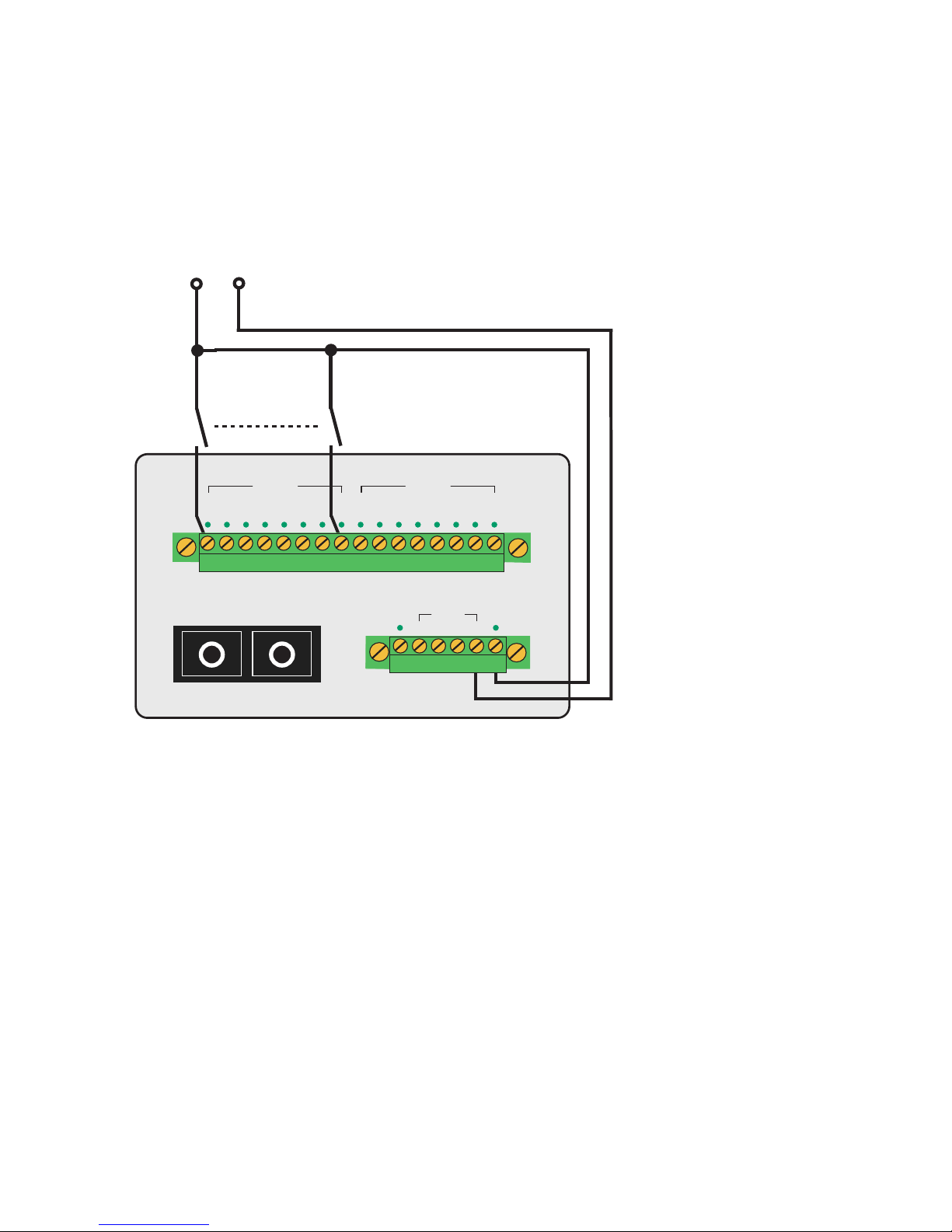
The basic wiring of the inputs for the Digital-IO Extender Set
can be seen in the following illustration:
The digital inputs of the Digital-I/O Extender Set 17635 are
„Type 3“ according to IEC 61131-2 and have a maximum input
voltage of 30V with respect to the device reference ground.
The lines to the digital inputs should not be longer than
necessary.
12..24V DC
+
-
Link VddGND
0 1 2 3 4 5 6 70 1 2 3 4 5 6 7
Outputs
Inputs
TxD RxD
Fiber Optic SC
Page 26
54
W&T Digital-I/O Extender Sets
Digital Outputs
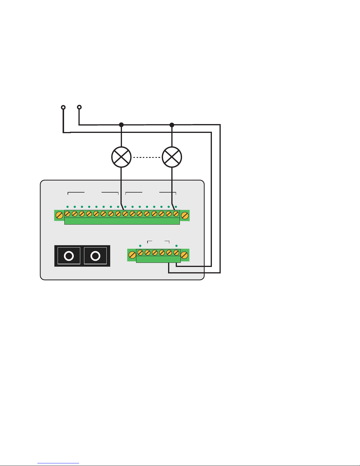
The basic wiring of the switching outputs for the Digital-IO
Extender Set can be seen in the following illustration:
The digital outputs of the Digital-I/O Extender Sets are current
sourcing and apply the voltage brought to Vdd to the output
terminals. Each of the outputs can switch a maximum current
of 0.5A. If loads with an inductive component (e.g. relays,
contactors, solenoids etc.) need to be switched, the outputs
must be additionally protected using recovery diodes.
The outputs have thermal overload protection and are short
circuit protected. In the OFF state a very low current of
approx. 10µA is used to check whether the outputs are
switched to a load. If LEDs are connected to the outputs, this
can result in a slight glow even in the rest state.
1
Link VddGND
12..24V DC
+
-
0 1 2 3 4 5 6 70 1 2 3 4 5 6 7
Outputs
Inputs
TxD RxD
Fiber Optic SC
Page 27

55
W&T Digital-I/O Extender Sets
Subject to error and alteration
Cable break response
The functionality of the glass fiber optic connection is
cycli cally monitored by a special safety communications
protocol. The status of the connection is indicated by the Link
LED and by a signal on the Link switching output.
An 8x DIL switch is provided on the top side of the unit for
configuring the cable break response, whereby the status of
the outputs when the fiber optic connection is interrupted
can be set for each individual output. The arrangement of the
DIL switches and output can be found on the label on the top
side of the unit.
The factory default setting is for all switches in the Off
position. If this setting is not changed, all the digital outputs
on the unit will turn off when the fiber optic connection is
interrupted.
This response can be inverted by setting the DIL switch
associated with an output to ON. This setting can be made
individually for each of the eight outputs.
Page 28

56
W&T Digital-I/O Extender Sets
Technical Data
Transmitted signals: 8x Digital In, 8x Digital Out
Digital-I/O connector: 16-pin plug-in screw terminal
Digital outputs: 8 outputs, 8V-30V, 0.5A,
Short circuit protected
Digital inputs: 8 inputs acc. to IEC61131-2, type 3
Input voltage: max. 30V
Signal delay: Input to output: max. 20ms
Glass fiber connector: SC/PC connectors
Fiber medium: Duplex singlemode
glass fiber cable 9/125µm
Transmitter type: Class 1 Laser Product
Wavelength: 1310 nm
Output power: min. -12dBm, max. -8dBm
Receiver sensitivity: max. -22dBm
Maximum input power: max. -3dBm
Optical budget: min. 10dB
Maximum distance: min. 20km @0,35dB/km
(40km on request)
Supply voltage: 8..30V DC
Current draw: typ. 30 mA at 12V DC
Temperature range: Storage: -40..+70°C
Operating: 0..+70°C
Humidity range: 5..90% rH (non condensing)
Life expectancy: > 25 years (@25°C ambient temp.)
Housing: Plastic housing for DIN rail mount
Dimensions: 105x75x45mm
Weight: approx. 300 g
Scope of delivery: 1x Digital-I/O Extender Set 8x8
Singlemode SC
 Loading...